

Page 1
GigaPico Next
AutoFocus
Users’ Manual 1.1
GeoDesy Kft. Telefon: 06-1-481-2050
Fax.: 06-1-481-2049
E-mail: info@geodesy-fso.com
http://www.geodesy-fso.com
1
Page 2

Table of contents
1 Introduction ...................................................................................................................... 4
1.1 What is FSO?........................................................................................................... 4
1.2 Why is it important? ............................................................................................... 4
1.3 Optical Free-space Transmission .......................................................................... 6
1.4 Typical applications ................................................................................................ 7
2 Interfaces for the Giga Next AF Series ........................................................................... 8
2.1 1000Mbps TP interface........................................................................................... 8
2.2 1000 Mbps FO interface ......................................................................................... 8
3 Sites of installation ........................................................................................................... 9
3.1 Key factors of operation ......................................................................................... 9
3.2 Preferred installation sites ..................................................................................... 9
3.3 Distance measurement .......................................................................................... 11
3.4 Direct sunshine ...................................................................................................... 11
4 Eye safety ........................................................................................................................ 12
5 The mounting bracket .................................................................................................... 13
5.1 Mounting brackets for the X Series .................................................................... 13
6 System installation ......................................................................................................... 15
6.1 On the table test .................................................................................................... 15
6.1.1 Alignment of the PX0500E1000TP ................................................................... 16
6.1.2 How to use the alignment base ........................................................................... 16
6.1.3 Fine tuning .......................................................................................................... 17
6.2 Meanings of the LCD ............................................................................................ 17
6.3 AF adjusment method .......................................................................................... 18
6.4 Connecting to your Network ................................................................................ 20
6.4.1 PoE 802.3 af connection. ................................................................................... 20
6.4.2 System layout ...................................................................................................... 20
6.4.3 System layout with GEO20 ................................................................................ 21
7 Management ................................................................................................................... 22
7.1 Features .................................................................................................................. 22
Login Screen and password ........................................................................................ 22
Head information screen ............................................................................................. 22
Status info screen ........................................................................................................ 23
Device setup ................................................................................................................ 24
Network Setup ............................................................................................................ 25
SNMP Setup ............................................................................................................. 27
GeoDesy Kft. Telefon: 06-1-481-2050
Fax.: 06-1-481-2049
E-mail: info@geodesy-fso.com
http://www.geodesy-fso.com
2
Page 3

Security ...................................................................................................................... 28
Auto-focus setup (AF) ................................................................................................ 28
Mandatory Management Activation ........................................................................... 30
Firmware update ......................................................................................................... 31
7.2 Network Interface software update ..................................................................... 33
7.2.1 Update cabel........................................................................................................ 35
GeoDesy Kft. Telefon: 06-1-481-2050
Fax.: 06-1-481-2049
E-mail: info@geodesy-fso.com
http://www.geodesy-fso.com
3
Page 4
1 Introduction
1.1 What is FSO?
FSO is free space optics provides point-point broadband communications using
Laser Light as the transmission medium.
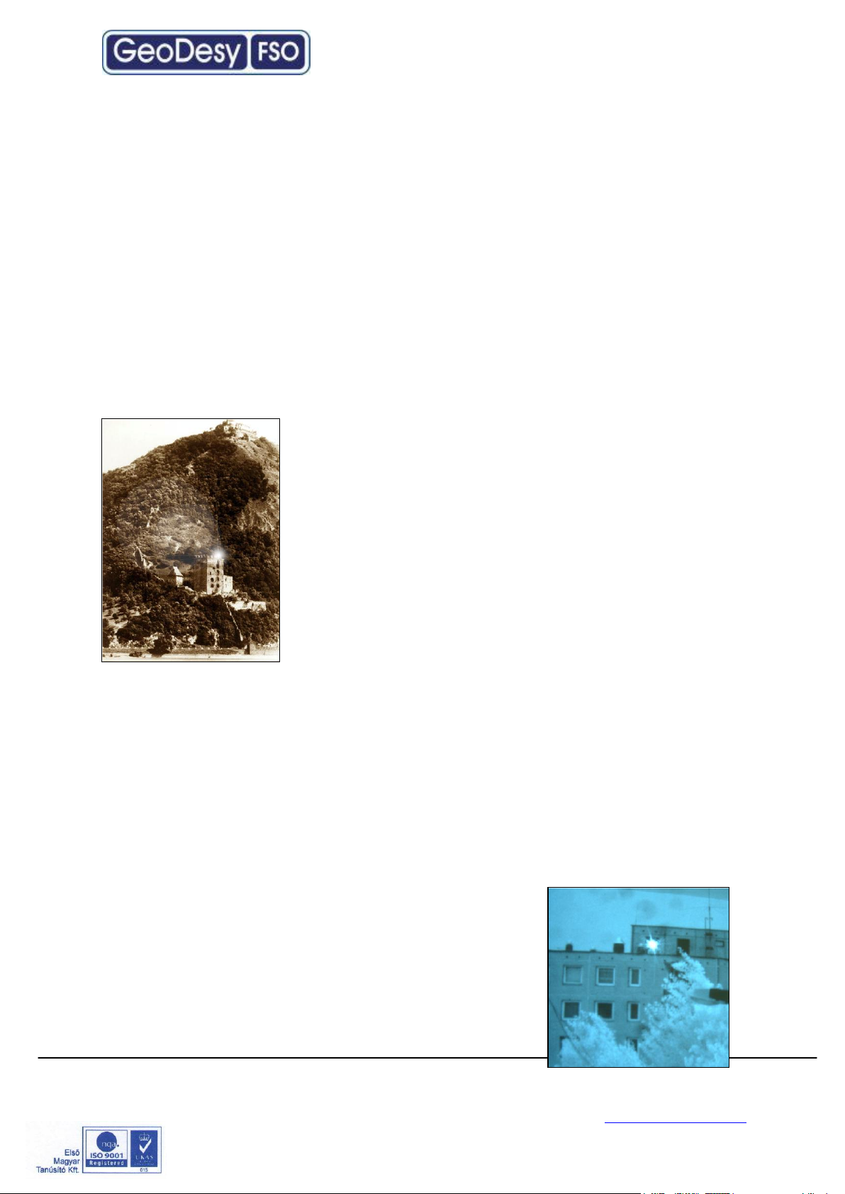
FSO is a state of art data communication method which is based on a very old
communication solution. Ancient Chinese developed a protection system against the
Mongol tribes, building watchtowers within the line of site to other towers. And as
soon as the towers saw some hostile sign on the horizon they use they shield to
reflect the sun to the remote towers. In this way the area could be prepared against
the attack in a very short period of time.
In the ancient times for this communication use the mirror
as a transmitter and the sunlight was the light source, and
the receiver was the remote guard’s eye. This basic
signalling method was developed later into up
communication device which used „line coding”. This
allowed the guards to tell the number of enemy, or the
direction they are coming from.
Current FSO systems use a laser-diode as a light source,
and a receptor diode (photo diode) to receive the signals
coming from the laser diode from the transmitter side. But
the basic elements are still the same: line of site between
the communication nodes, and individual line coding. It is all about performance.
GeoDesy FSO offers FSO systems with the highest power budget available on
the market.
1.2 Why is it important?
Because of in the ancient Chinese times, the rain, the fog, or even the cloudy
weather, could impact the operation of the whole system.
In the FSO units, comprising light source and receiver the cloud problem was
solved, but development conditions still can impair
performance. To go throw the rain, the fog, or snow you
need more and more power to be seen from the remote
side. Achievable power levels are limited by a number of
factors including eye safety.
In this way there is no other choice to see more than
„training the eye”. Making the receiver more and more
GeoDesy Kft. Telefon: 06-1-481-2050
Fax.: 06-1-481-2049
E-mail: info@geodesy-fso.com
http://www.geodesy-fso.com
4
Page 5

sensitive to sense delight emitted from the remote side. GeoDesy FSO offers high
transmit power and also very hard receiver sensitivity. These two factors combined
to provide one of the best performing FSO systems on the market today.
To meet the demands for every higher bandwidth, GeoDesy FSO (Europe) Limited
continues to invest heavily in research and development with the newest product line
which offers Gigabit speeds being launched.
This manual describes the GeoDesy FSO Next series of free space laser
transmission system.
The GeoDesy FSO Next product range offers cost effective reliable free space
laser transmission for two Mbps up to 1000 Mbps data to the air, where a clean line
of site is available. It delivers the most effective point-to-point connection between
computer networks or telephone exchanges.
No need for installing cables, no rental costs, no licensing requirements.
Ideal for urban areas or city centres, where the use of these lines are expensive.
Suitable for factories or industrial environments where high noise level can interfere
with the transmitted data. The best choice to make a connection across rivers and
other natural or artificial obstacles, where cable is not available.
The transmission technique used in the GeoDesy FSO devices provides
transparent and wire-speed data transfer with virtually zero latency. Because they
use infrared light as the transmission medium, GeoDesy FSO system do not
require frequency licenses and the transmission is not effected by electro-magnetic
or radio-frequency interference. Basically the GeoDesy FSO link can be
considered as a virtual fibre in the air, which ends in real fibre optic cable at both
ends.
Our product is built using high quality components for operation in even the most
adverse conditions.
Metal housing gives robust, waterproof environment for the electronics.
The shield protects the device from direct sunlight and provides extra air isolation.
The GeoDesy FSO X systems comprise two laser-heads
one at each end. The interface connections are housed in the outdoor unit together
with the PSU of the system.
Best practises were employed in cost engineering throughout the development of
GeoDesy FSO.
GeoDesy Kft. Telefon: 06-1-481-2050
Fax.: 06-1-481-2049
E-mail: info@geodesy-fso.com
http://www.geodesy-fso.com
5
Page 6

1.3 Optical Free-space Transmission
The principle used in free space laser transmission is very similar to the one is used
for fibre optic transmission. The difference is while fibre optic devices use electronics
and optics optimized for transmission to the air. Also one can observe to the
similarity in the transmission properties. No galvanic contact, no ground-loops, no
need for surge protection, noise immunity, long distances, high bandwidth.
What makes it unique – and difficult to design – is that it does not require any
transmission medium like fibre or copper, but it has to cope with the dynamically
changing parameters. For instance while the attenuation of an optical fibre is
constant, the attenuation of the atmosphere between the laser units can change
dramatically (depending on the weather conditions).
The laser-heads are usually placed on top of building, where the clean line of site is
guaranteed and the beam cannot be interrupted.
In the head the incoming signal is amplified, encoded, and then drives the laserdiode. The transmitter optics assures the proper beam shape and controls the beam
divergence. The receive optics perceives and directs the transmitter signal to the
photo diode. The diode converts it back into electrical, than it is decoded, amplified
and converted.
There are several things that can influence the quality of transmission. We can
classify those factors into three main groups.
System conditions - transmitting power, transmitter’s wavelength, beam divergence,
receiver optics diameter, receiver sensitivity, parameters of optical system and
casing. These parameters determine the system’s characteristic at a certain
distance and are controlled by system design and factory set up.
Weather conditions - molecular absorption, particle scattering and turbulence. These
elements have great effect on the operational conditions of the system. We do not
have very much influence on them; proper product selection can eliminate the
undesirable effects.
Environmental conditions - building movements, direct sunlight, refractive surfaces.
These are also key factors related to the installation sites and can be controlled by
appropriate site survey and system installation
GeoDesy Kft. Telefon: 06-1-481-2050
Fax.: 06-1-481-2049
E-mail: info@geodesy-fso.com
http://www.geodesy-fso.com
6
Page 7
Corporate
LAN
ISP
1.4 Typical applications
Most typically the GeoDesy FSO Next product are is used to interconnect LANs. The system is protocol transparent, thus other applications also can be taken into
consideration. Appropriate interface converters are needed and system bandwidth
must be matched for that.
Here we collected some circumstances, where the deployment of the GeoDesy
FSO is the most adequate as a cost effective solution.
Those are:
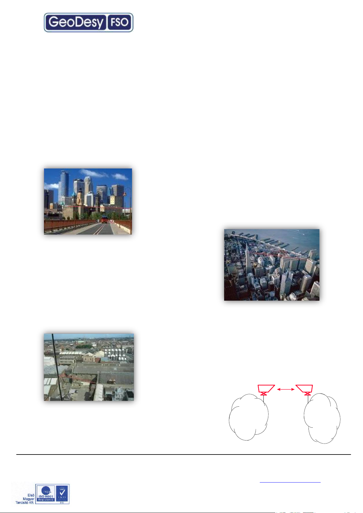
Areas with natural or artificial obstacles
Where cable is actually not an alternative, like
across rivers or railways or in rugged terrain.
Urban
areas
Where only leased lines are available with
limited speed, and high rental cost. With
GeoDesy FSO links you can establish on line
LAN-to-LAN connections.
Industrial areas
Where you have noisy environment with high EMI
or RFI. Factory buildings, airport objects can be
connected through laser link.
ISP connections
Where high
bandwidth is required. ISP’s can offer high-speed links
to their customers or trunks can be established
between ISP’s instead of expensive leased lines.
GeoDesy Kft. Telefon: 06-1-481-2050
Fax.: 06-1-481-2049
E-mail: info@geodesy-fso.com
http://www.geodesy-fso.com
7
Page 8
2 Interfaces for the Giga Next AF Series
2.1 1000Mbps TP interface
The GeoDesy FSO Giga Next AF series products are designed to provide
easy-to-use and cost-effective solution for interconnecting Local Area Networks. By
utilizing standard Category 5e cable and using standard IEEE802.3af interface the
deployment of the system is easier than ever before. The transparent and wire
speed data transfer together with virtually zero latency assures the easy integration
of the system in all environments.
The Giga Next AF systems should be considered as repeaters in the network. So
the installation distance between the head and the network device is 100m. The
distance on a back to back site is maximum 5 meters, between the heads without
signal regeneration.
The Giga Next AF systems connecting to the network with two RJ 45 cable which
provides the power required for operation and the data. The system requires IEEE
802.3af Power over Ethernet switch or power injector. The power consumption suits
to the standards described in the standard. Also provides fast and easy connection
for the management system for more details please see the chapters below. The
system is certified Class 1M product, this way 100% eye safe.
2.2 1000 Mbps FO interface
The GeoDesy FSO Giga Next MF system is ready to be upgraded with a Single
or Multi mode SC fiber interface with SX or LX option.
The power is provided via the same cable as in the case of the TP interface
systems.
GeoDesy Kft. Telefon: 06-1-481-2050
Fax.: 06-1-481-2049
E-mail: info@geodesy-fso.com
http://www.geodesy-fso.com
8
Page 9

3 Sites of installation
3.1 Key factors of operation
There are four key issues that the site survey has to shed light on. Proper system
operation cannot be guaranteed without satisfying all of the four requirements.
Clear line of sight - The entire optical path between the two ends must be free
of any obstacles. It not only means that one has to see the other side, but other
possible sources of disturbance should also be taken into consideration. For
example there might be turbulence above the roofs and other constructions, and this
can cause fraction or scattering of the beam or snow accumulation on roofs too
close to the beam can influence or even interrupt communication.
Solid mount surface - is the key for long-term operation. Since the diameter of
the beam is limited, it is extremely important to mount the unit on a stable structure
with the possible smallest movement. This way the receiver of the remote unit
cannot get out of the beam due to the movement of the opposite head.
East-West orientation - although the receiver optics are equipped with optical
filters to protect the receiver diode from the effect of undesired light sources, direct
sunshine can cause saturation of the diode. This prevents the system from working
properly for several minutes a day at certain times of the year. In most cases this
effect can be avoided by careful selection of the mounting spot.
In order to comply with the requirements of the successful installation - including the
discussed four key factors and other criteria - the following matters should be taken
into consideration.
3.2 Preferred installation sites
All buildings and constructions have a certain movement of their own. It’s
determined by the structure and material of the building. Metal structures can shift or
twist due to temperature changes. Wooden construction can expand or shrink with
any changes in humidity. Give preference to concrete or brick buildings. On the
other hand high structures like towers, skyscrapers or poles are always subject to
movement. Mount the support frame to walls of the building or near corners, as they
are the most stable spots. Use appropriate consoles for wall mounting. If a stand is
used on the top of
building, secure it directly to the ceiling or to the concrete cornice wherever is
possible. Do not fix stands to insulating materials as they can slowly sink under the
weight of the unit and with temperature changes. Big chimneys and smokestacks
may look stable, but as their inner temperature varies they can also move. Vibration
caused by heavy traffic, trains and elevators etc. may slowly move the system out of
GeoDesy Kft. Telefon: 06-1-481-2050
Fax.: 06-1-481-2049
E-mail: info@geodesy-fso.com
http://www.geodesy-fso.com
9
Page 10
Preferred installation
sites
Pay attention to
Avoid (*)
Concrete wall
Behind window
Soft materials
Brick wall
Old constructs
Chimneys
Microwave towers
Wooden constructs
Metal masts or Frames
Hidden heat isolations,
like Styrofoam
its specified direction. Another important consideration is to provide enough space
for alignment and to have the potential for future maintenance. Consider that the
support frame is usually heavy, so the selected spot should be easily accessible.
(*)
In cases where installations are listed under “AVOID” cannot be avoided than special mounting
accessories to be designed and special installations must be used.
It is not only the building that has to be solid, but the support structure too. Antenna
poles and security camera holders are not suitable for the GeoDesy FSO units.
GeoDesy Kft. Telefon: 06-1-481-2050
Fax.: 06-1-481-2049
E-mail: info@geodesy-fso.com
http://www.geodesy-fso.com
10
Page 11
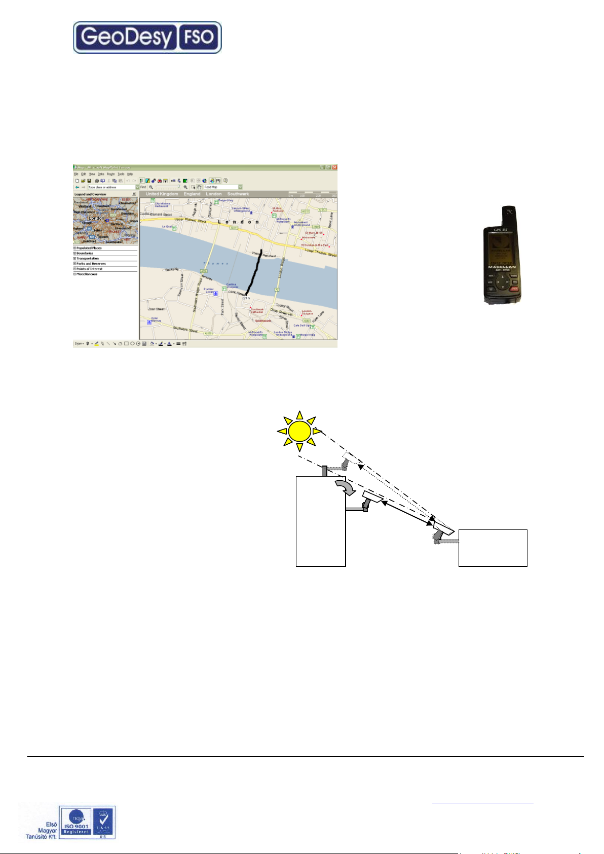
3.3 Distance measurement
Because the units were designed, and calibrated for certain distance operations the
higher distance will decrease the availability. GeoDesy FSO pre-calibrates and pretests every unit shipped to the customer. To ensure that the unit you are about to
buy fits to the needs, the first step
is to measure the distance. The
best way to measure it is by GPS
(Global Positioning
System), these units
are accurate enough to
determine the distance
between two points.
For more details please
refer to the GPS
manufacturer
handbook. Also there are several
other ways to measure the
distance. If you know the exact
address you can use mapping software like MapPoint or Auto route.
3.4 Direct sunshine
To prevent the sun shining directly
into the receiver optics, first one
has to determine the orientation of
the link. Try to avoid East-West
orientation wherever it is possible.
Examine both sides of the link at
sunset and sunrise and find a
position where the sun cannot get
behind any of the heads. Be aware
that the path of the sun is changing
throughout the year.
GeoDesy Kft. Telefon: 06-1-481-2050
Fax.: 06-1-481-2049
E-mail: info@geodesy-fso.com
http://www.geodesy-fso.com
11
Page 12

Type : LB P0500E1000TP
S/N : LBH-«s/n»
Input Power : -48VDC IEEE 802.3af compilant
Laser : 1M
Wavelength : 785nm
Manufactured by: GeoDesy FSO 1162 Budapest,
Kondorfa u. 6-8, HUNGARY, Tel.:+36-1-453-7440 Fax.:+36-1-240-3570
www.GeoDesy FSO.com
INVISIBLE LASER RADIATION
DO NOT VIEW DIRECTLY WITH
OPTICAL INSTRUMENTS
CLASS 1M LASER PRODUCT
4 Eye safety
There are no two installation spots of the same kind, the buildings or structures, the
available space and the accessibility of the place will be different in each case.
Nevertheless, as a general rule it is very important to select the installation site so
that nobody can look directly into the transmitter. For this reason place the head
either so high (on the side wall of the building) or so close to the edge of the building
(on a parapet on the rooftop) that no person can approach it accidentally and can
get into the beam path. Set up barriers if necessary and put warning signs at
prominent places.
The laser heads are provided with all labels and hazard warnings required by the
laser standard. There are warning labels on both the left and right side of the
protective cover next to the optical window and there is a warning and an informative
label on the rear side of the laser head.
GeoDesy Kft. Telefon: 06-1-481-2050
Fax.: 06-1-481-2049
E-mail: info@geodesy-fso.com
http://www.geodesy-fso.com
12
Page 13

5 The mounting bracket
In the following chapter you will find detailed description of the bracket fastenings.
5.1 Mounting brackets for the X Series
GeoDesy FSO provides the mounting bracket and all the necessary components
for X series units. A simple fixing technique of this bracket can be seen on the
following figure, required tools are as follows:
- drilling machine
- 10 mm wrench
Bracket sizes:
Length: 463mm
Leg Width: 263mm
Head Width: 130mm
Drill size: 10mm wall drilling
Installation steps:
Place the bracket on the wall
Mark the wall with a permanent marker
Use your 10mm wall drill to drill all of the holes into the wall
Clean the holes
Place the wall-plugs into the holes (please note that some times you need to
use hammer to put the wall-plugs into the hole, if you have to please be
careful not to break the wall-plug )
Place the bracket to the wall an line it up to the holes
Put the screws into the wall-plug through the hole on the leg of the bracket
(please see the figure above)
Tighten up the screws
GeoDesy Kft. Telefon: 06-1-481-2050
Fax.: 06-1-481-2049
E-mail: info@geodesy-fso.com
http://www.geodesy-fso.com
13
Page 14

Packet list for the bracket:
3pcs 8x110 screw for bracket fixing
3pcs 8x100 plastic wall-plug for bracket fixing
2pcs M6x90 bolt Head fixing
3pcs M6x25 screw Head fixing
3pcs M6 bolt head fixing
6pcs 6mm spacer bracket and head fixing
6pcs 6mm spring spacer bracket and head fixing
Mounting Hole Patterns
GeoDesy Kft. Telefon: 06-1-481-2050
Fax.: 06-1-481-2049
E-mail: info@geodesy-fso.com
http://www.geodesy-fso.com
14
Page 15

6 System installation
6.1 On the table test
Warning! Do not look either into the transmitter or the receiver optics because at
this distance even the reflected laser beam can be dangerous to your eyes.
Operating the system on much shorter distance than presumed originally can cause
saturation or even permanent damage to the receiver. Always use optical
attenuators for this kind of test.
The on-the-table test needs careful planning and careful use during the test period.
The units should be placed at about 2 m distance from each other with optical
windows facing one another. Put an appropriate optical attenuator (Attenuating foil
or cardboard with several small holes) between the heads. Make all the necessary
connection as described below to connect your network equipment (computer or
protocol analyzer) to the heads and power up the units. Turn ON the PoE injector
and check if the power LED is ON on the head.
You should be able to align the units without any tool and get full received level on
the signal strength LED’s. Make sure that the “Saturation”(OV) indicator is OFF.
Adjust your attenuators if necessary to avoid saturation of the receivers.
Please note that at this short distance, specially the longer distance links can reflect
to the remote site or even to the same head. If you experience full receiving level,
with no traffic throughput, in that case try to move the heads slightly units out of the
reflection zone.
Please also take in consideration that the laser beam is concentrated and in such a
short distance can harm your eyes, every time you test the units on short distance,
do it with extra care. Never look into the sighting device if the remote laser is turned
on. We strongly suggest to double check the power connection before you turn on
the device. Handle the power connection with extra care. Safety first.
After obtaining the desired received level, check the data connection between
devices. Using computers or appropriate testing devices.
On the table tests are perfect for troubleshooting (If there is a transmission problem,
check the status of the connecting devices (e.g. Link signal or cable polarity) and
cables.) in a controlled area. If you experience some problems during the test,
please try to test the connected equipments with a direct connection.
GeoDesy Kft. Telefon: 06-1-481-2050
Fax.: 06-1-481-2049
E-mail: info@geodesy-fso.com
http://www.geodesy-fso.com
15
Page 16

6.1.1 Alignment of the PX0500E1000TP
The first step after the unit was placed to
the bracket, and the units facing each other.
On the back of the receiver you can find the
LEDs and LCD screen for the local received
level and the remote received level.
This help will be very useful because as soon as you have received – which is very
easy to achieve – you can see the effect of your local sides movement to the other
side. For further information please check the Meanings of the LCDs chapter.
6.1.2 How to use the alignment
base
1. Loose the Coarse locker on the
horizontal as well as on the
vertical side with a 10mm
spanner
2. Move the head left - right up
down you should use the built in
telescope to lit up a few LEDs on
the remote end.
3. When you have lined the unit up
to a rough position lock the
coarse locker with a 10mm
spanner.
4. Repeat step 1-4 on the remote
end.
5. On the bottom of the unit you can find fine tuning screws one for horizontal
and one for vertical.
6. No tightening is needed on any other screw than the coarse locker.
GeoDesy Kft. Telefon: 06-1-481-2050
Fax.: 06-1-481-2049
E-mail: info@geodesy-fso.com
http://www.geodesy-fso.com
16
Page 17

6.1.3 Fine tuning
1. Site A start moving the
laserhead with the horizontal
fine adjustment screw by
looking at the Remote end
received level
2. Using the fine adjustment
screws, lighten as many LEDs
as possible
3. Repeat step 1-2 on Site B.
4. If necessary try step 1-2 on
both sites again.
6.2 Meanings of the LCD
Power: The head is powered up.
RX-OK: Received beam is good for communication.
TP Lk: Copper link between the head and the
Network equipment.
R-LS: The recived signal form the remote end is
modulated and .
RV/TLs: Remote end is visible for the management system and there is TP
connected to remote end – same as TP-Lk but displays it on the remote end.
Please press the button and look at the LCD scren!
1.screen
Loc (local level): Local Received level
Rem (remote level): Remote Sites Received level
Op-optimal
Ov-overload
REM:?FSO Currently on FSO channel searching the Remote side.
REM:?Backup Currently on Backup channel searching the Remote side.
REM:?FSO or Backup Auto Software desides on what to search for.
2.screen
HeadSN: Laser head serial number.
0000001
IP address: default IP address:192.168.100.220 or 192.168.100.221
After factory reset the IP address is always: 192.168.100.221
3.screen 4.screen 5.screen
Temperature -AF mode position manual 000 tech@geodesy.hu
-AF mode auto
Here shows that the auto fucus with is enabled or disabled.
GeoDesy Kft. Telefon: 06-1-481-2050
Fax.: 06-1-481-2049
E-mail: info@geodesy-fso.com
http://www.geodesy-fso.com
17
Page 18

6.3 AF adjusment method
What is AF after all? AF stands for Auto Focus. Geodesy FSO Giga Next AF is
equipped with the lates innovation from Geodesy. An automatic focusing control
system. The system is capable of changing its beam divergency depending on the
changes of the environment. In the case if the weather gets bad, the system will
decrease the beam size, to concentrate the distributed beam power, to ensure more
stable operation.
IMPORTANT! Auto focus adjustment does not work if there is no remote level!
Remote connection required for the Auto focus adjustment.
The installation of the Giga Next AF is pretty much the same as the standard system
installation. To make sure that the AF system won’t kick in during the alignment,
ensure that the AF is set to disabled, which is the factory default.
The default settings of the Auto Focus (AF) laser heads is manual mode (disabled).
The factory beam divergence is set for 200m, this way the alignment of the system
will be easy on every installation distance.
Please do not change the setting of the AF laser heads to auto focus when there is
no connection between the two heads.
GeoDesy Kft. Telefon: 06-1-481-2050
Fax.: 06-1-481-2049
E-mail: info@geodesy-fso.com
http://www.geodesy-fso.com
18
Page 19

Alignment steps
1. using the crosshair align the units into a roughly aligned position. Please note
that the alignment scope will not be able to provide with a perfect alignment,
this will have to be done using the fine alignment screws referring to the
received level screen on the LCD panel.
2. using the fine adjustment screws on the alignment base set the units to the
highest received level possible. (for further details on how to perform the fine
adjustment refer to 6.2.2 and 6.2.3 chapters)
Default distance setting of all Giga Next AF laser heads for 200m. As you can see in
below sketch, “+25 STEP” equals ~ 2 cm larger laser beam over 100 meters.
For example, if you would like to install the laser heads over 350 meters than you
will need smaller beam size to reach bigger distance (compared to the default
200m), so click on “-100 STEP” which will make the laser beam narrower and will
be proper for 350m. While clicking on the “STEP” buttons please check the remote
received level on the laser head.
Please perform the same operation on the other side.
3. After we have got the proper level, please click on “Save position as default”
button. As you have clicked on the “Save position as default” button the laser
heads will enable the AUTO FOCUS mode (enabled). The equipment will
automatically improve the remote level to the most ideal position.
Note: Geodesy FSO shall not be responsible for any failures from improper handling
of the device. If any other screw than the coarse lockers or the fine adjustment is
moved, might decrease the stability of the installation.
Trick for the reliable alignment
Please note that the beam has a powerfull ring on the side of the head and easily can be set to this ring but this is far not as big
for further help. Or contact GeoDesy FSO technical support.
as the core part of the beam. So every time you have an
alignment please make sure that when you see the maximum
LED s or a relativly high received level. Keep on moving to
determine where the core part of the beam is. This can be
done easily by looking at the received level you will see that
the received level moves up then it will start move down than
up again. During this time you just had the head moving into
one direction. If you have any doubt on how to do the alignment please contact your distributor
GeoDesy Kft. Telefon: 06-1-481-2050
Fax.: 06-1-481-2049
E-mail: info@geodesy-fso.com
http://www.geodesy-fso.com
19
Page 20

1. Orange/White
TX+
2. Orange
TX
3. Green/White
RX+
4. Blue
+VIN
5. Blue/White
+VIN
6. Green
RX-
7. Brown/White
-VIN
6.4 Connecting to your Network
6.4.1 PoE 802.3 af connection.
BOX1.1(FO)
6.4.2 System layout
BOX1.0(FO)
GeoDesy Kft. Telefon: 06-1-481-2050
Fax.: 06-1-481-2049
E-mail: info@geodesy-fso.com
http://www.geodesy-fso.com
20
Page 21

6.4.3 System layout with GEO20
Beside the GeoDesy laser equipment (buckup) you can only use GeoDesy’s GEO20
Radio equipment. In the case of using a different backup solution, could cause
undesired operation. Please referr to support@geodesy-fso.com for more
inforamation about the compatibility.
BOX 1.0(FO)
GeoDesy Kft. Telefon: 06-1-481-2050
Fax.: 06-1-481-2049
E-mail: info@geodesy-fso.com
http://www.geodesy-fso.com
21
Page 22

7 Management
7.1 Features
The Inband network-monitoring unit is a newly developed highly featured monitoring
for GeoDesy FSO manufactured laser links. This high quality equipment allows the
user to monitor the link statuses such as detector voltage transmitter status, and
many other features of the Laser link. Nevertheless, this chapter is intended to
describe the usage of this network monitoring, and its connection and relationship
with the GeoDesy FSO laserheads.
Login Screen and password
The GeoDesy FSO unit arrives with preset values. Such
as user name and password. We strongly recommend
you to change the password after the unit was installed.
The default username is admin, and the password is
admin. If you forget your password contact technical
support to receive your fail-safe password.
Head information screen
The head information screen is the main navigation panel through this screen you
will be able to navigate into the submenu, of the monitoring system.
Device Name: displays the name of the device. Individually can be changed
Total Uptime: Diplays the elapsed time from the last boot of the device
IP address: Displays the IP(Internet Protocol) address of the device which must be a
unique identifier in the network.
Managed head: displays the managed head type.
Head Serial Number: This is the head serial number and during the Activation
process we will ask for this number.
GeoDesy Kft. Telefon: 06-1-481-2050
Fax.: 06-1-481-2049
E-mail: info@geodesy-fso.com
http://www.geodesy-fso.com
22
Page 23

Status info screen
Clicking on the Device Setup you will enter the main status information screen,
which will give you good summarized information of the device, such as status
information of the transmitters, detector level, or temperature values.
Laser ON: Transmitter transmitts
Temperature: ambient temperature inside the device. These units were designed for
extreme conditions and should not have any problems under -20C to 70C. In fact the
unit is emitting some heat so the temperature displayed is not the air temperature
outside the head. For example the temperature can be -10C outside but in the
device it wont go below -1 or -2. The value will display error depeding on the setting
was done device setup. There is no default value for this setting, only a suggested
value, which is 60C.
Detector level: shows the local heads received level. In volts, the maximum is 7 volts
and the minimum is 0.2 volts. The value will display error depeding on the setting
was done device setup.
Remote Detector level: this value is dispalyed form reception of the remote head.
The maximum is 7 volts and the minimum is 0.2 volts.
TP_Link: displays that there is connection over the TP cable.
FSO Link: displays that there is valid signal received from the remote end.
Remote is visible: this status information is a good information about the connection
over the two laserheads if this status is OK that means that there is data transferred
over the link.
Remote TP Link: shows that whether the remote end is connected into the switch
and the TP interface is available.
PSU: The PSU of the device is sending the OK signal.
RX OK: this information is showing that the receiver is enabled. It basically means
that there is valid signal with necessary strenght is received in the local end.
GeoDesy Kft. Telefon: 06-1-481-2050
Fax.: 06-1-481-2049
E-mail: info@geodesy-fso.com
http://www.geodesy-fso.com
23
Page 24

Device setup
The device setup screen leads you to the main monitoring options. Here the alarms
can be set and main information about the Laser head.
Device name: uniqe identifier of
the device
Managed head: Type of the
laserhead
Temperature alert level: when the temperature reach this value, the alarm will be
triggered.
Auto recovery time: It determines the time before the heads start the recovery
process in the case of link disconnection.
Motherboard Serial number: Mainboard serial number inside the head (Not the same
as the Head Serial Number)
Motherboard Firmware version: This is the version number of the Firmware For the
update procedure please referr to the Firmware update section.
Head Serial number: Serial number of the unit. Should be the same number as the
one on the back of the unit. If the number is missing or not match up with the one on
the back, during activation this is the number you will have to let the support know.
GeoDesy Kft. Telefon: 06-1-481-2050
Fax.: 06-1-481-2049
E-mail: info@geodesy-fso.com
http://www.geodesy-fso.com
24
Page 25

Software version: software of the laser head.
NPASW SW version: Network Port Auto SWitchover version.
GBIC-compatibility mode:On or OFF.
If there are two connectors under the laser head them the GBIC-compatibility mode
should be ON (the is GBIC-module in it) but if there are 3 or 4 them the GBICcompatibility modeshould be OFF (the is NPASW module it).
Network Setup
Clicking on the IP Setup link you can have access to the Ethernet module of the
system, this will make easy access to the IP number and/or port settings. These
settings are sensitive setting and some of them cannot be restored by the user.
Please always do the changes with extra care! If you have doubt in any step, do not
hesitate to contact the technical support of the manufacturer website for further
information.
Local IP: the IP address of the local
device can be set in this box. If the IP
address is set retype it to your browser.
Enter only valid IP addresses, if you forget the IP address, you will have to turn to
our support and in some cases return the device for reseting the IP address. Please
always do the IP change with care.
GeoDesy Kft. Telefon: 06-1-481-2050
Fax.: 06-1-481-2049
E-mail: info@geodesy-fso.com
http://www.geodesy-fso.com
25
Page 26

Subnet mask: you can set the subnet
mask of the local device.
Default gateway: The default getway
setting for the local device.
Auto MDI/MDI-X: this enables the Auto
setting for the MDI/MDI-X, some old
switch types might report
incompatibility here it can be switched
off. (Auto MDI/MDI-X can be turned off
even in the Xs systems)
Remote IP:This will tell this device what
the IP address of the remote device is.
This setting wont change the remote
units IP address, this just identify the remote device for the local device. If the IP
address is not valid all diplays will go error and the display of the remote sites
received level on the laserhead will be disabled!
SWAP: swaps the local and the remote IP address. This function will require a swap
on the remote end to make the entire system working. If this function is used restart
the system.
NPASW mode: Network Port Auto SWitchover
FSO: Transmition throgh FSO.
Backup: Backup channel (FSO disabled)
Auto: If NPASW mode is Auto then the actual channel chosen by the software
is ON.(FSO or backup)
NPASW time limit: Minimum time needed to switch from back up to FSO(minimum 2
seconds)
NPASW treshold LOW:switches to backup
NPASW treshold HIGH:switches to FSO
GeoDesy Kft. Telefon: 06-1-481-2050
Fax.: 06-1-481-2049
E-mail: info@geodesy-fso.com
http://www.geodesy-fso.com
26
Page 27

SNMP Setup
One of the main features of the device is the SNMP(Simple Network Monitoring
Protocol). The SNMP settings can be set on this page.
Trap address: The IP address of the SNMP trap over the network.
Trap events in the system you have
possibility to setup three different trap
event.
For further details on the trap event see
Trap event list chapter of this book. In this section there are the settings of the
SNMP Agent.
SNMP trap address: IP address of the
SNMP tarp computer
Read Community and Read Write
community To the setup of the Read
and the Read-Write community, the
preset value is public
Agent UDP Port the SNMP agent UDP
port number (1…1000) the preset value
is 162
Trap UDP Port: the SNMP trap UDP
port number (1…1000) the preset value
is 161
Traps:
The Laserhead is sending two different traps:
LaserHeadAlarm (OID: 1.3.6.1.4.1.17857.0.1201) This trap will be sent after any
of the alarms will go on (for alarm setting please see chapter 5.4)
LaserHeadAlarmCancel (OID: 1.3.6.1.4.1.17857.0.1202) After the alarm goes off
this trap will be sent
GeoDesy Kft. Telefon: 06-1-481-2050
Fax.: 06-1-481-2049
E-mail: info@geodesy-fso.com
http://www.geodesy-fso.com
27
Page 28

Security
On the security section you can set the username and the password for the unit. If
you have forget the usernam and/or the password please contact The technical
support.
MGM Trusted-host filtering: Here you can adjust two addresses wehre you can till in
from which computer with you reach the MGM! To adjust you will hove to adjust a
filter.
Filter adjust:
Off: Turned off.
IP: Only see the IP address.
MAC: Only see the MAC address
IP+MAC: Either IP or MAC address should be equal to the adjusted.
IP&MAC: Both IP and MAC addresses should be equal to the adjusted.
Auto-focus setup (AF)
Automatic divergence corrections:
Enabled (auto): adjust beam size to the best level according to the remote level.
Disabled (manual): It disables the automatic adjustment routine, and lets the user
adjust the beam size by using the „STEP” buttons.
Last activity: which the AF (auto focus) has done.
idle: AF was not active..
setting default: saves the standard settings.
moving default: return to default settings.
moving to open: opens to widest beam.
GeoDesy Kft. Telefon: 06-1-481-2050
Fax.: 06-1-481-2049
E-mail: info@geodesy-fso.com
http://www.geodesy-fso.com
28
Page 29

increasing remote load: the AF adjusts the laser beam to increase remote level.
decreasing remote load: the AF adjusts the laser beam to decrease remote level.
optimizing remote load: the AF adjusts the laser beam to optimal remote level.
Manual focus control: After setting the Manual Focus controls you can adjust the
manual focus by clicking on the „STEP” buttons. You can increase the beam size, by
clicking on the plus numbers or you can decrease it by clicking on the minus. The
amount of the increase or the decrease depends on the number of steps .
GeoDesy Kft. Telefon: 06-1-481-2050
Fax.: 06-1-481-2049
E-mail: info@geodesy-fso.com
http://www.geodesy-fso.com
29
Page 30

Mandatory Management Activation
Thank you for buying our product. Please read this note carefully. From software
version (3.2.1218/R090x)!
The product you have bought has fully functional management software, which has
limitation only in time. The unit activation request should be sent to
activation@geodesy-fso.com. And the activation code will be issued, later and sent
to the email address give, or can be accessed from your local distributor.
After 90 days if the system was not activated the data transmission will be
degraded!
Activation process:
1. Login to the devices through a web browser using the
IP:192.168.100.220,192.168.100.221
2. Default login name:admin and password:admin
3. Click on Evaluation period
4. Click on Get a key
5. Fill in the table and click on send
6. We will return the activation key
Limitations:
- All Next-Series(100MB/s) limitation course 1-60 days unlimited, for 61-80 days
10MB/s, for 81-90 days 1MB/s, beyond 90 days 100KB/s (MGM-Option).
- All GigaNext-Series(1000 MB/s) will be limited after the 90th day, when the whole
bandwidth will be blocked, except the management system.
GeoDesy Kft. Telefon: 06-1-481-2050
Fax.: 06-1-481-2049
E-mail: info@geodesy-fso.com
http://www.geodesy-fso.com
30
Page 31

Firmware update
The firmware update has the following steps:
Run FTP client
Log-in to the Laser-head
Copy Geodesy_FWUpdate_Vxx.sys over
Log in the laserhead
Click on update
Wait 50-60 seconds
Restart the laserhead
Run FTP client
FTP client setup
IP address: the IP address of the device (192.168.100.220 or 192.168.100.221 as a
factory default ) or the IP address you gave to the system earlier – same as the IP
address for the Web management.
User name: same as for the web management (default admin)
Password: same as for the web management (default admin)
If you have passive mode please turn it off, otherwise the system will not connect.
GeoDesy Kft. Telefon: 06-1-481-2050
Fax.: 06-1-481-2049
E-mail: info@geodesy-fso.com
http://www.geodesy-fso.com
31
Page 32

copy the file over to the Laserhead
Log off the FTP server
Now the Update button will be active
Click on update and the update process will start it takes upto 60 seconds. The
LEDs on the back of the device will go off than lit one after the other.
Make sure that the system power is fixed and the power will not go off during the
update process. If the LEDs froze, wait 2-3 minutes before unplugging the power
cable, and repluging again.
GeoDesy Kft. Telefon: 06-1-481-2050
Fax.: 06-1-481-2049
E-mail: info@geodesy-fso.com
http://www.geodesy-fso.com
32
Page 33

7.2 Network Interface software update
1. Connect the RJ11 and RS232 cable (update cabel)
between the laser head and the PC.
2. Enter into the management of the laser head and into the device info.
4.Click on the „Update” button.
5.Click on OK button.
6. Start the Total Commander program and start PIC32.exe program.
7. Choose COM1 port.
8.Click ont the Connect button.
9.Click on Erase button.
GeoDesy Kft. Telefon: 06-1-481-2050
Fax.: 06-1-481-2049
E-mail: info@geodesy-fso.com
http://www.geodesy-fso.com
33
Page 34

10. Click on Load Hex File button
and then choose the attached .HEX
file (new software)
11.Click on the Program button.
12.Click on Run application button:
the laser head will restart with the
new software.
13. Click on the Disconnect button and close the program.
GeoDesy Kft. Telefon: 06-1-481-2050
Fax.: 06-1-481-2049
E-mail: info@geodesy-fso.com
http://www.geodesy-fso.com
34
Page 35

7.2.1 Update cabel
GeoDesy Kft. Telefon: 06-1-481-2050
Fax.: 06-1-481-2049
E-mail: info@geodesy-fso.com
http://www.geodesy-fso.com
35
 Loading...