

Page 1
. 6
Users’ Manual
Telefon: 06
info@geodesy
http://www.
GeoDesy Kft.
H-1116 Budapest, Kondorfa str
X-Series
1.5e
-8.
E-mail:
1
-1-481-2050
Fax.: 06-1-481-2049
-fso.com
geodesy-fso.com
Page 2

. 6
Table of contents
................................
................................
portant?
space Transmission
Typical applications
aces for the X Series
100Mbps TP interface
................................
Key factors of operation
Preferred installation sites
Distance measurement
................................
................................
................................
Mounting brackets for the X Series
................................
................................
Alignment of the
How to use the alignment base
................................
ng at the installation site
Meanings of the LEDs
Connecting to your Network
................................
................................
Login Screen and password
nformation screen
................................
................................
................................
................................
................................
Network statistics page
X extra MGM functions
Mandatory Management Activation
................................
Reloading factory default settings
Telefon: 06
info@geodesy
http://www.
................................
................................
...............................
................................
................................
...............................
.............................
................................
................................
................................
..........................
................................
................................
................................
................................
................................
................................
................................
................................
................................
...............................
................................
................................
................................
................................
................................
.............................
................................
................................
................................
................................
................................
...........................
................................
................................
................................
................................
1 Introduction
1.1 What is FSO?
1.2 Why is it im
1.3 Optical Free-
1.4
2 Interf
2.1
3 Sites of installation
3.1
3.2
3.3
3.4 Direct sunshine
4 Eye safety
5 The mounting bracket
5.1
................................
................................
................................................................
................................
................................................................
................................................................
................................................................
................................
................................
................................
................................................................
................................
................................
................................
................................
...................... 4
........... 4
4
.......... 6
7
8
8
........... 9
......................... 9
..................... 9
11
...... 11
........................ 12
.... 13
.... 13
6 System installation
6.1 On the table test
6.1.1
Fine tuning
6.1.2 Pronto-X setti
6.1.3
6.1.4
7 Management
7.1 Features
Head i
Status info screen
Device setup
IP Setup
SNMP Setup
Security
Pronto-
................................
................................
X series ................................
................................
................................
................................
................................
................................
................................
................................
................................
................................................................
................................
................................
................................
................................
................................
................................................................
................................
................................
......... 15
.... 15
................... 16
.............. 16
................. 17
17
........................ 19
............... 20
................... 21
.................. 21
........................ 21
21
........ 22
................ 23
....................... 24
............. 25
...................... 26
26
.................. 28
........... 29
7.2 Firmware update
7.3
GeoDesy Kft.
H-1116 Budapest, Kondorfa str
-8.
................................
................................
E-mail:
2
... 30
....... 32
-1-481-2050
Fax.: 06-1-481-2049
-fso.com
geodesy-fso.com
Page 3

. 6
Setting up the SMP
SNMPc Installation
Configuration of the SNMPc Management console
Compiling GeoDesy
Using SNMP to monitor the link
Generating failure
MP Technology
................................
................................
................................
Telefon: 06
info@geodesy
http://www.
............................
.............................
................................
................................
................................
...............................
..............................
................................
................................
................................
7.4
7.4.1
7.4.2
7.4.3
7.4.4
7.4.5
7.4.6 SN
Trap event list
8 Warranty conditions
9 Privacy statement
................................................................
................................................................
-FSO Mib file ................................
................................
................................................................
................................................................
................................
................................
................................
32
33
........... 34
..... 37
........ 39
41
43
........... 50
....... 51
........... 52
GeoDesy Kft.
H-1116 Budapest, Kondorfa str
-8.
E-mail:
3
-1-481-2050
Fax.: 06-1-481-2049
-fso.com
geodesy-fso.com
Page 4
. 6
1 Introduction
is free space optics provides point
Laser Light as the transmission medium.
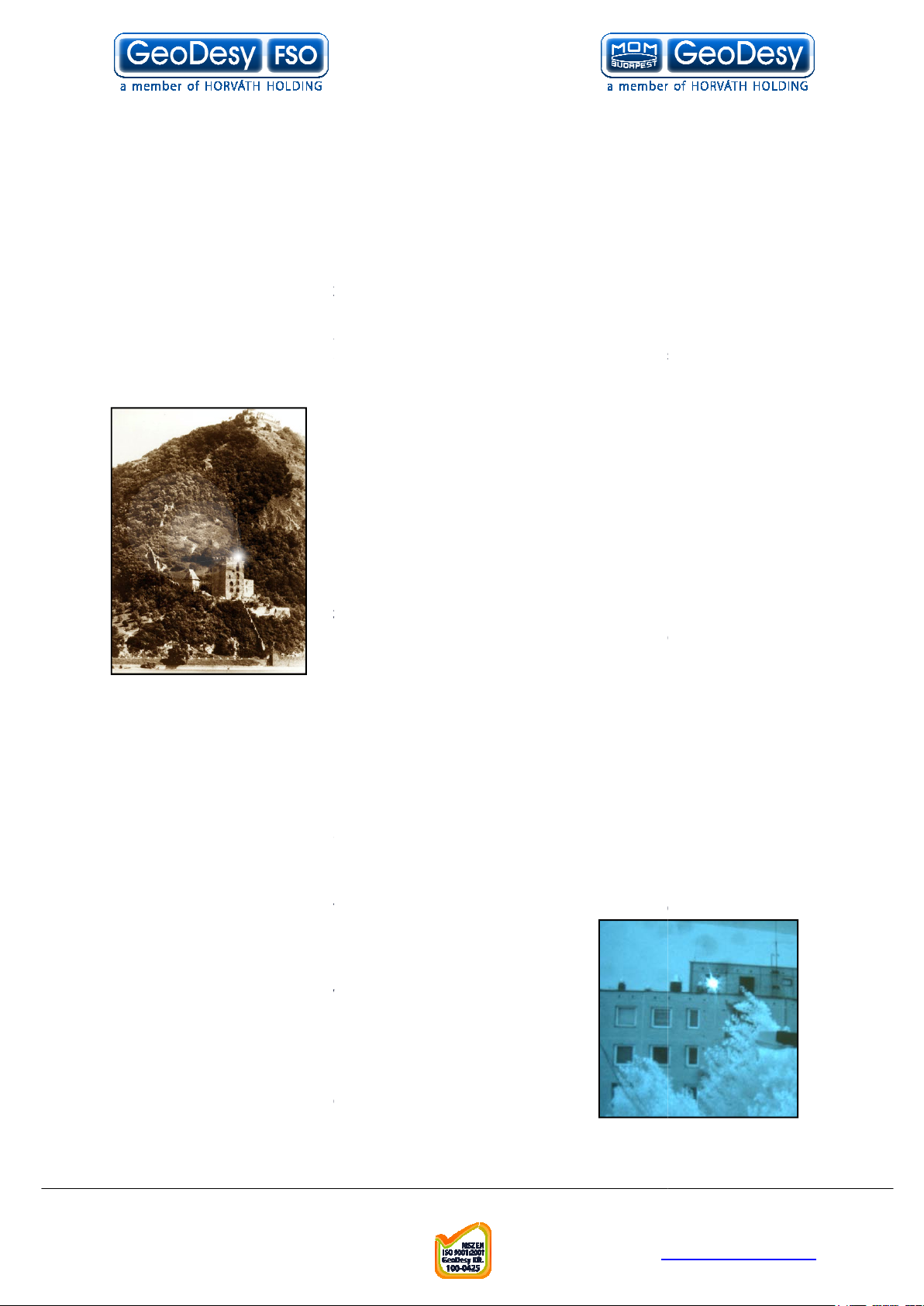
is a state of art data communication method which is based on a very old
communication solution. Ancient Chinese developed a protection system against the
Mongol tribes, building watchtowers within the line of site to other towers. And as
rs saw some hostile sign on the horizon they use they shield to
reflect the sun to the remote towers. In this way the area could be prepared against
the attack in a very short period of time.
In the ancient times for this communication use the mirror
as
the receiver was the remote guard’s eye. This basic
signalling method was developed later into up
communication device which used „line coding”. This
allowed the guards to tell the number of enemy, o
direction they are coming from.
Current
and a receptor diode (photo diode) to receive the signals
coming from the laser diode from the transmitter side. But
the basic elements are still the same: line
the communication nodes, and individual line coding. It is all about performance.
FSO
Why is it important?
Because of in the ancient Chinese times, the
weather, could impact the operation of the whole system.
units, comprising light source and receiver the cloud problem was
solved, but development conditions still can impair
performance. To go throw the rain
need more and more power to be seen from the remote
side. Achievable power levels are limited by a number of
factors including eye safety.
In this way there is no other choice to see more than
„training the eye”. Making the receiver
sensitive to sense delight emitted from the remote side.
offers high transmit power and also
Telefon: 06
info@geodesy
http://www.
point broadband communications using
a transmitter and the sunlight was the light source, and
diode as a light source,
systems with the highest power budget available on
rain, the fog, or even the cloudy
1.1 What is FSO?
FSO
FSO
soon as the towe
-
GeoDesy FSO
the market.
1.2
In the
FSO
offers
r the
FSO
systems use a laser-
of site between
, the fog, or snow you
more and more
GeoDesy FSO
GeoDesy Kft.
H-1116 Budapest, Kondorfa str
-8.
E-mail:
4
Fax.: 06-1-481-2049
-1-481-2050
-fso.com
geodesy-fso.com
Page 5

. 6
very hard receiver sensitivity. These two factors combined to provide one of the best
systems on the market today.
et the demands for every higher bandwidth,
continues to invest heavily in research and development with the newest product line
which offers Gigabit speeds being launched.
This manual describes the
Next
laser transmission for two Mbps up to 1000 Mbps data to the air, where a clean line
of site is available. It delivers the most eff
computer networks or telephone exchanges.
No need for installing cables, no rental costs, no licensing requirements.
Ideal for urban areas or city centres, where the use of these lines are expensive.
actories or industrial environments where high noise level can interfere
with the transmitted data. The best choice to make a connection across rivers and
other natural or artificial obstacles, where cable is not available.
The transmission technique used
speed data transfer with virtually zero latency. Because they
use infrared light as the transmission medium,
require frequency licenses and the transmission is not effected by electro
frequency interference. Basically the
considered as a virtual fibre in the air, which ends in real fibre optic cable at both
Our product is built using high quality components for operation in even the most
Metal housing gives robust, waterproof environment for the electronics.
The shield protects the device from direct sunlight and provides extra air
interconnection units (OIU)
in the outdoor unit together with the PSU of the system.
Best practises were employed in
Telefon: 06
info@geodesy
http://www.
GeoDesy FSO
series of free space laser
product range offers cost effective reliable free space
point connection between
d
GeoDesy FSO
GeoDesy FSO
heads and the two indoor
one at each end. The interface connections are housed
cost engineering throughout the development of
performing
To me
transmission system.
The
GeoDesy FSO
Suitable for f
transparent and wire-
or radio-
ends.
FSO
(
Europe)
GeoDesy FSO Next
ective point-to-
in the
GeoDesy FSO
evices provides
system do not
link can be
Limited
-magnetic
adverse conditions.
The
GeoDesy FSO
GeoDesy FSO
GeoDesy Kft.
H-1116 Budapest, Kondorfa str
X
systems comprise two laser-
-
.
-8.
E-mail:
5
Fax.: 06-1-481-2049
isolation.
-1-481-2050
-fso.com
geodesy-fso.com
Page 6

. 6
space Transmission
The principle used in free space laser transmission is very similar to the one is used
for fibre optic transmission. The difference is while fibre optic devices
and optics optimized for transmission to the air. Also one can observe to the
similarity in the transmission properties. No galvanic contact, no ground
need for surge protection, noise immunity, long distances, high bandwidth.
and difficult to design
transmission medium like fibre or copper, but it has to cope with the dynamically
changing parameters. For instance while the attenuation of an optical fibre is
attenuation of the atmosphere between the laser units can change
dramatically (depending on the weather conditions).
heads are usually placed on top of building, where the clean line of site is
guaranteed and the beam cannot be interrupted.
he head the incoming signal is amplified, encoded, and then drives the laser
diode. The transmitter optics assures the proper beam shape and controls the beam
divergence. The receive optics perceives and directs the transmitter signal to the
he diode converts it back into electrical, than it is decoded, amplified
There are several things that can influence the quality of transmission. We can
classify those factors into three main groups.
transmitting power,
receiver optics diameter, receiver sensitivity, parameters of optical system and
casing. These parameters determine the system’s characteristic at a certain
distance and are controlled by system design and factory
molecular absorption, particle scattering and turbulence. These
elements have great effect on the operational conditions of the system. We do not
have very much influence on them; proper product selection can eliminate the
-
These are also key factors related to the installation sites and can be controlled by
appropriate site survey and system installation
Telefon: 06
info@geodesy
http://www.
is that it does not require any
transmitter’s wavelength, beam divergence,
building movements, direct sunlight, refractive surfaces.
1.3 Optical Free-
What makes it unique –
constant, the
The laser-
In t
photo diode. T
and converted.
use electronics
-loops, no
–
-
System conditions -
Weather conditions -
undesirable effects.
Environmental conditions
set up.
GeoDesy Kft.
H-1116 Budapest, Kondorfa str
-8.
Fax.: 06-1-481-2049
E-mail:
6
-1-481-2050
-fso.com
geodesy-fso.com
Page 7
. 6
tions
GeoDesy FSO
The system is protocol transparent, thus other applications also can be taken into
consideration. Appropriate interface converters are needed and system bandwidth
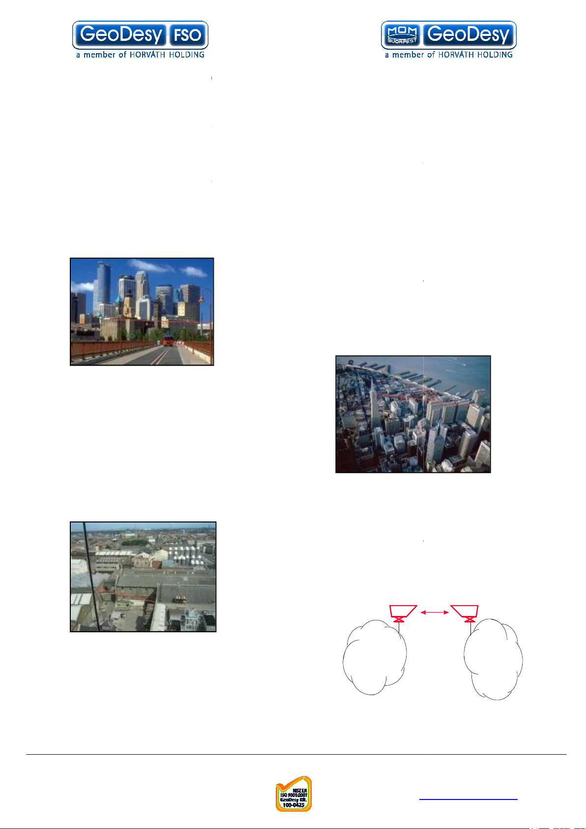
Here we collected some circumstances, where the
is the most adequate a
Areas with natural or artificial obstacles
Where only leased lines are available with
limited speed, and high rental cost. With
links you can establish on line
Where high bandwidth is required. ISP’s can offer
speed links to their customers or trunks can be
established between ISP’s instead of expensive leased lines.
Telefon: 06
info@geodesy
http://www.
used to interconnect LAN
ployment of the
Where cable is actually not an alternative, like
noisy environment with high EMI or
RFI. Factory buildings, airport objects can be
Corporate
LA
ISP
1.4 Typical applica
Most typically the
must be matched for that.
FSO
Those are:
Next
s a cost effective solution.
rivers or railways or in rugged terrain.
products are
de
-s.
GeoDesy
across
Urban areas
GeoDesy FSO
LAN-to-LAN connections.
Industrial areas
ISP connections
Where you have
connected through laser link.
high-
GeoDesy Kft.
H-1116 Budapest, Kondorfa str
-8.
Fax.: 06-1-481-2049
E-mail:
7
-1-481-2050
-fso.com
geodesy-fso.com
Page 8

. 6
the
100Mbps TP interface
X PoE
effective solution for interconnecting Local Area Networks. By utilizing
standard Category 5 cable and using standard IEEE802.3af interface the
deployment of the system is easier than ever
speed data transfer together with virtually zero latency assures the easy integration
of the system in all environments.
systems should be considered as repeaters in the network. So the
installation distance between t
distance on a back to back site is maximum 5 meters, between the heads
systems connecting to the network with an RJ 45 cable which provides
the power required for operation and the data. The system requires IEEE 802.3af
Power over Ethernet switch or power injector. The power consumption suits to the
e standard. Also provides fast and easy connection for the
management system for more details please see the chapters below. The system is
M product
Telefon: 06
info@geodesy
http://www.
series products are designed to provide easy
. The transparent and wire
he head and the network device is 100m. The
2 Interfaces for
2.1
The
GeoDesy FSO
and cost-
The
X PoE
signal regeneration.
The
X PoE
standards described in th
X Series
-to-use
before
without
certified
Class 1
, this way 100% eye safe.
GeoDesy Kft.
H-1116 Budapest, Kondorfa str
-8.
Fax.: 06-1-481-2049
E-mail:
8
-1-481-2050
-fso.com
geodesy-fso.com
Page 9

. 6
Sites of installation
Key factors of operation
r key issues that the site survey has to shed light on. Proper system
operation cannot be guaranteed without satisfying all of the four requirements.
The entire optical path between the two ends must be free
only means that one has to see the other side, but other
possible sources of disturbance should also be taken into consideration. For
example there might be turbulence above the roofs and other constructions, and this
can cause fraction or scattering of th
close to the beam can influence or even interrupt communication.
-
the beam is limited, it is extremely important to mount the unit on a
with the possible smallest movement. This way the receiver of the remote unit
cannot get out of the beam due to the movement of the opposite head.
West orientation
protect the receiver diode from the effect of undesired light sources, direct
sunshine can cause saturation of the diode. This prevents the system from working
properly for several minutes a day at certain times of the year. In most cases this
e avoided by careful selection of the mounting spot.
In order to comply with the requirements of the successful installation
discussed four key factors and other criteria
ed installation sites
All buildings and constructions have a certain movement of their own. It’s
determined by the structure and material of the building. Metal structures can shift or
twist due to temperature changes. Wooden construction can expand or sh
any changes in humidity. Give preference to concrete or brick buildings. On the
other hand high structures like towers, skyscrapers or poles are always subject to
movement. Mount the support frame to walls of the building or near corners, as they
are the most stable spots. Use appropriate consoles for wall mounting. If a stand is
building, secure it directly to the ceiling or to the concrete cornice wherever is
possible. Do not fix stands to insulating materials as they can sl
weight of the unit and with temperature changes. Big chimneys and smokestacks
may look stable, but as their inner temperature varies they can also move. Vibration
caused by heavy traffic, trains and elevators etc. may slowly move the sy
its specified direction. Another important consideration is to provide enough space
for alignment and to have the potential for future maintenance. Consider that the
support frame is usually heavy, so the selected spot should be easily accessib
Telefon: 06
info@geodesy
http://www.
e beam or snow accumulation on roofs too
term operation. Since the diameter of
although the receiver optics are equipped with optical
the following matters should be taken
owly sink under the
3
3.1
There are fou
Clear line of sight
of any obstacles. It not
Solid mount surface
East-
filters to
-
is the key for long-
-
stable structure
effect can b
into consideration.
3.2 Preferr
used on the top of
- including the
-
rink with
stem out of
GeoDesy Kft.
H-1116 Budapest, Kondorfa str
-8.
Fax.: 06-1-481-2049
E-mail:
9
le.
-1-481-2050
-fso.com
geodesy-fso.com
Page 10

. 6
Preferred installation
In cases where installations are listed under “AVOID” cannot be avoided than special mounting
accessories to be designed and special installations must be used.
It is not only the building that has to be solid, but the support structure too. Antenna
s and security camera holders are not suitable for the
Telefon: 06
info@geodesy
http://www.
Avoid (*)
Soft materials
Chimneys
Wooden constructs
Metal masts or Frames
Hidden heat isolations,
like Styrofoam
GeoDesy FSO
sites
Concrete wall
Brick wall
(*)
Pay attention to
Behind window
Old constructs
Microwave towers
pole
units.
GeoDesy Kft.
H-1116 Budapest, Kondorfa str
-8.
Fax.: 06-1-481-2049
E-mail:
10
-1-481-2050
-fso.com
geodesy-fso.com
Page 11
. 6
Distance measurement
Because the units were designed, and calibrated for certain distance operations the
higher distance will decrease the availability.
tests every unit shipped to the customer. To ensure that the unit you are about to
address you can use mapping software like MapPoint
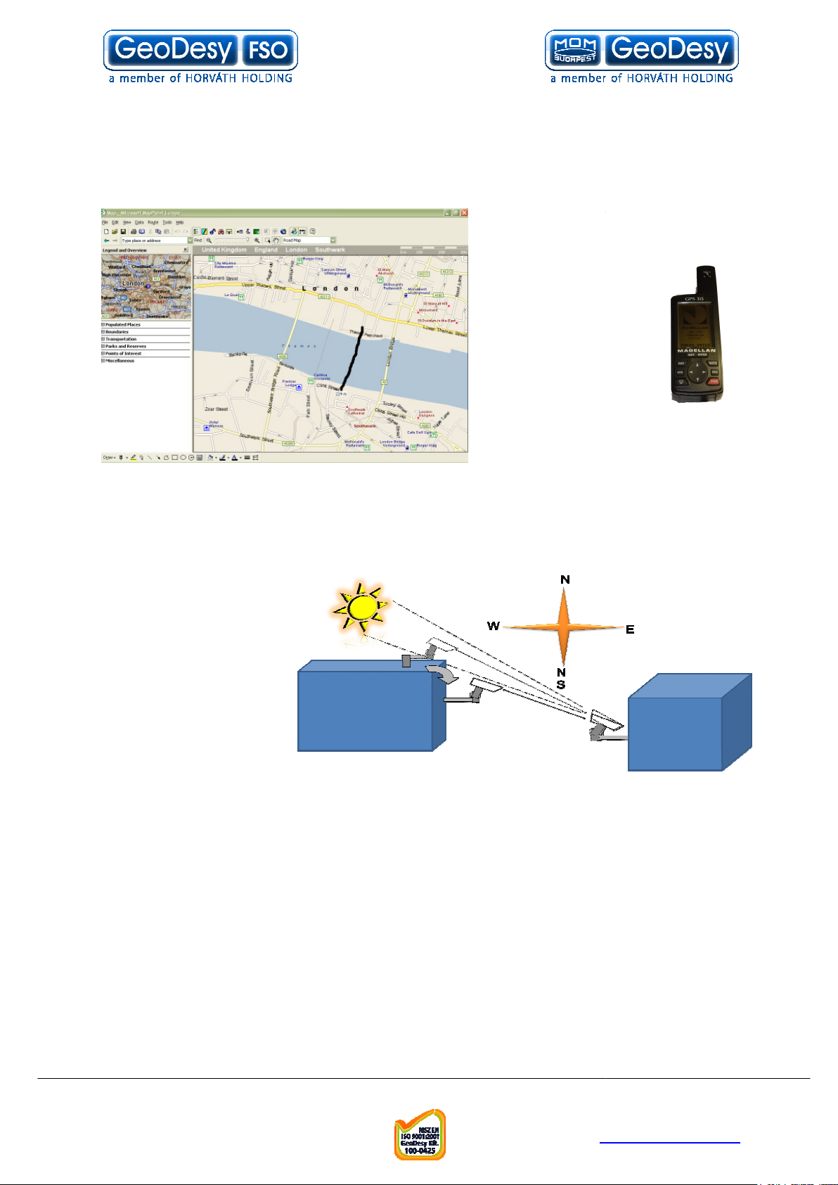
behind any of the heads. Be aware that the path of the sun is changing throughout
Telefon: 06
info@geodesy
http://www.
calibrates and pre
buy fits to the needs, the first step
is to measure the distance. The
best way to measure it is by GPS
(Global Positioning
System), these units
ccurate enough to
determine the distance
between two points.
For more details
please refer to the
GPS manufacturer
handbook. Also there are several
other ways to measure the
distance. If you know the exact
or Auto route.
3.3
GeoDesy FSO pre-
are a
-
3.4 Direct sunshine
To prevent the sun
shining directly into the
receiver optics, first one
has to determine the
orientation of the link.
Try to avoid East-West
orientation wherever it
is possible. Examine
both sides of the link at
sunset and sunrise and
find a position where
the sun cannot get
the year.
GeoDesy Kft.
H-1116 Budapest, Kondorfa str
-8.
Fax.: 06-1-481-2049
E-mail:
11
-1-481-2050
-fso.com
geodesy-fso.com
Page 12

. 6
There are no two installation spots of the same kind, the buildings or structures, the
able space and the accessibility of the place will be different in each case.
Nevertheless, as a general rule it is very important to select the installation site so
that nobody can look directly into the transmitter. For this reason place the head
so high (on the side wall of the building) or so close to the edge of the building
(on a parapet on the rooftop) that no person can approach it accidentally and can
get into the beam path. Set up barriers if necessary and put warning signs at
The laser heads are provided with all labels and hazard warnings required by the
laser standard. There are warning labels on both the left and right side of the
protective cover next to the optical window and there is a warning and an informative
l on the rear side of the laser head.
INVISIBLE LASER RADIATION
Telefon: 06
info@geodesy
http://www.
48VDC IEEE 802.3af compilant
Manufactured by: GeoDesy FSO 1162
-
www.GeoDesy FSO.com
4 Eye safety
avail
either
prominent places.
labe
DO NOT VIEW DIRECTLY WITH
OPTICAL INSTRUMENTS
CLASS 1M LASER PRODUCT
Type : LB X-0200-E100TP
S/ : LBH-«s/n»
Input Power : Laser : 1M
Wavelength : 785nm
Kondorfa u. 6-8, HUNGARY, Tel.:+36-1-453
Budapest,
7440 Fax.:+36-1-240-3570
GeoDesy Kft.
H-1116 Budapest, Kondorfa str
-8.
Fax.: 06-1-481-2049
E-mail:
12
-1-481-2050
-fso.com
geodesy-fso.com
Page 13
. 6
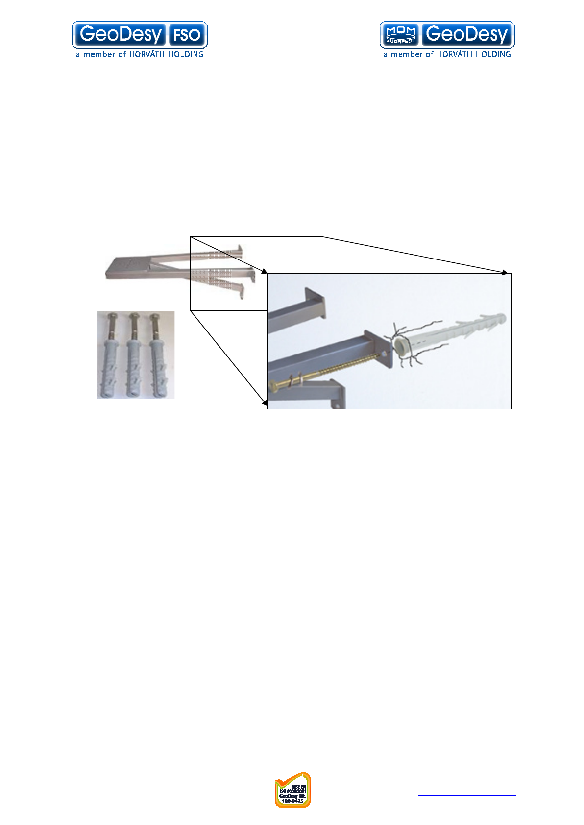
The mounting bracket
you will find detailed description of the bracket fastenings.
Mounting brackets for
provides the mounting bracket and all the necessary components
units. A simple fixing technique of this bracket can be seen on the
following figure, required tools are as follows:
Length:
Leg Width:
Head Width:
Drill size:
Place the bracket on the wall
with a permanent marker
Use your 10mm wall drill to drill all of the holes into the wall
plugs into the holes (please note that some times you need to
use hammer to put the wall
careful not to break the wall
Place the bracket to the wall an line it up to the holes
Put the screws into the wall
(please see the figure above)
Tighten up the screws
Packet list for the bracket:
s 8x110 screw for bracket fixing
plug for bracket fixing
Telefon: 06
info@geodesy
http://www.
plugs into the hole, if you have to please be
plug through the hole on the leg of the bracket
5
In the following chapter
5.1
GeoDesy FSO
for X series
- drilling machine
- 10 mm wrench
the X Series
Bracket sizes:
Installation steps:
•
• Mark the wall
•
• Clean the holes
• Place the wall-
•
•
•
3pc
463mm
263mm
130mm
10mm wall drilling
-
-plug )
-
3pcs 8x100 plastic wall-
GeoDesy Kft.
H-1116 Budapest, Kondorfa str
-8.
E-mail:
13
-1-481-2050
Fax.: 06-1-481-2049
-fso.com
geodesy-fso.com
Page 14
. 6
2pcs M6x90 bolt Head fixing
3pcs M6x25 screw Head fixing
3pcs M6 bolt head fixing
6pcs 6mm spacer bracket and head fixing
6pcs 6mm spring spacer bracket and head fixing
Telefon: 06
info@geodesy
http://www.
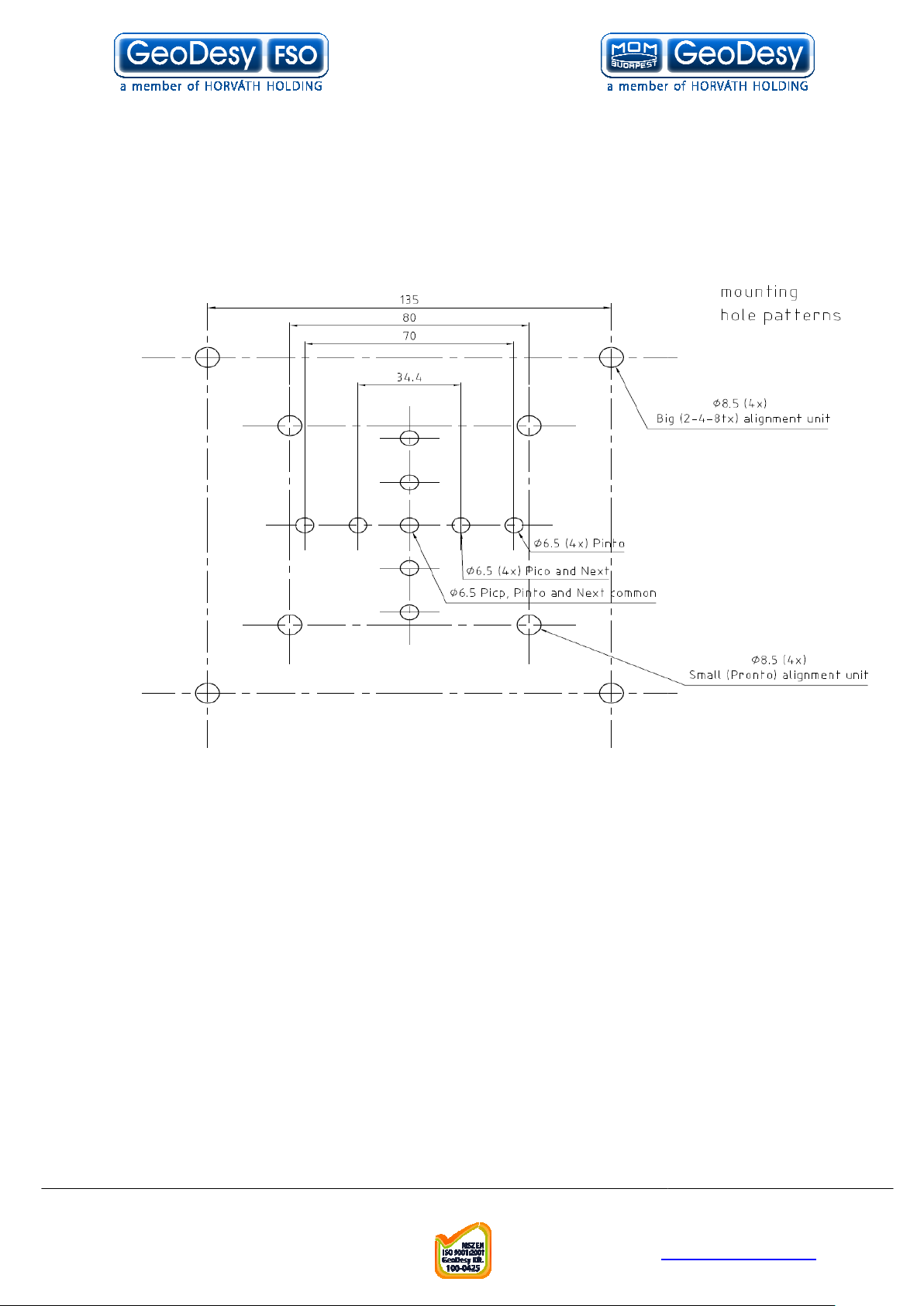
Mounting Hole Patterns
GeoDesy Kft.
H-1116 Budapest, Kondorfa str
-8.
E-mail:
14
-1-481-2050
Fax.: 06-1-481-2049
-fso.com
geodesy-fso.com
Page 15
. 6
System installation
On the table test
Do not look either into the transmitter or the receiver optics because at
this distance even the reflected laser beam
Operating the system on much shorter distance than presumed originally can cause
saturation or even permanent damage to the receiver. Always use optical
attenuators for this kind of test.
table test needs careful plan
The units should be placed at about 2 m distance from each other with optical
windows facing one another. Put an appropriate optical attenuator (Attenuating foil
or cardboard with several small holes) between th
connection as described below to connect your network equipment (computer or
protocol analyzer) to the heads and power up the units. Turn ON the Outdoor
Interconnection Units and check if the power LED is ON on the head.
should be able to align the units without any tool and get full received level on
the signal strength LED’s. Make sure that the “Saturation” indicator is OFF. Adjust
your attenuators if necessary to avoid saturation of the receivers.
this short distance, specially the longer distance links can reflect
to the remote site or even to the same head. If you experience full receiving level,
with no traffic throughput, in that case try to move the heads slightly units out of the
Please also take in consideration that the laser beam is concentrated and in such a
short distance can harm your eyes, every time you test the units on short distance,
do it with extra care. Never look into the sighting device if the remot
on. We strongly suggest to double check the power connection before you turn on
the device. Handle the power connection with extra care. Safety first.
After obtaining the desired received level, check the data connection between
Using computers or appropriate testing devices.
On the table tests are perfect for troubleshooting (If there is a transmission problem,
check the status of the connecting devices (e.g. Link signal or cable polarity) and
cables.) in a controlled area. If y
please try to test the connected equipments with a direct connection.
Telefon: 06
info@geodesy
http://www.
be dangerous to your eyes.
ning and careful use during the test period.
e heads. Make all the necessary
ou experience some problems during the test,
6
6.1
Warning!
The on-the-
You
Please note that at
can
reflection zone.
devices.
e laser is turned
GeoDesy Kft.
H-1116 Budapest, Kondorfa str
-8.
Fax.: 06-1-481-2049
E-mail:
15
-1-481-2050
-fso.com
geodesy-fso.com
Page 16
. 6
X series
The first step after the unit was placed to the
bracket, and turns the units facing each other.
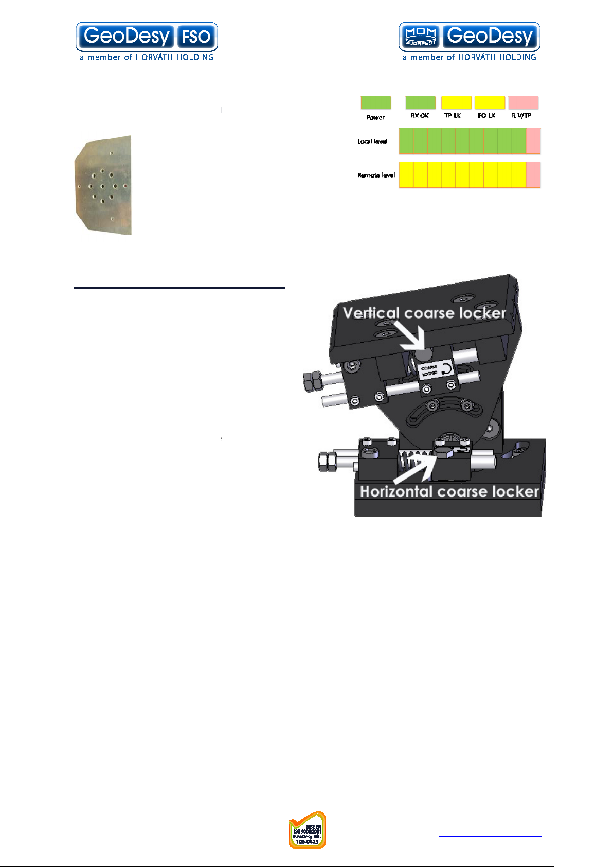
On the back of the receiver you can
find the LEDs for the local received
level and the remote received level.
This help will be very useful because
as soon as you have
very easy to achieve
vement to the other side. For further information please check the
Meanings of the LEDs
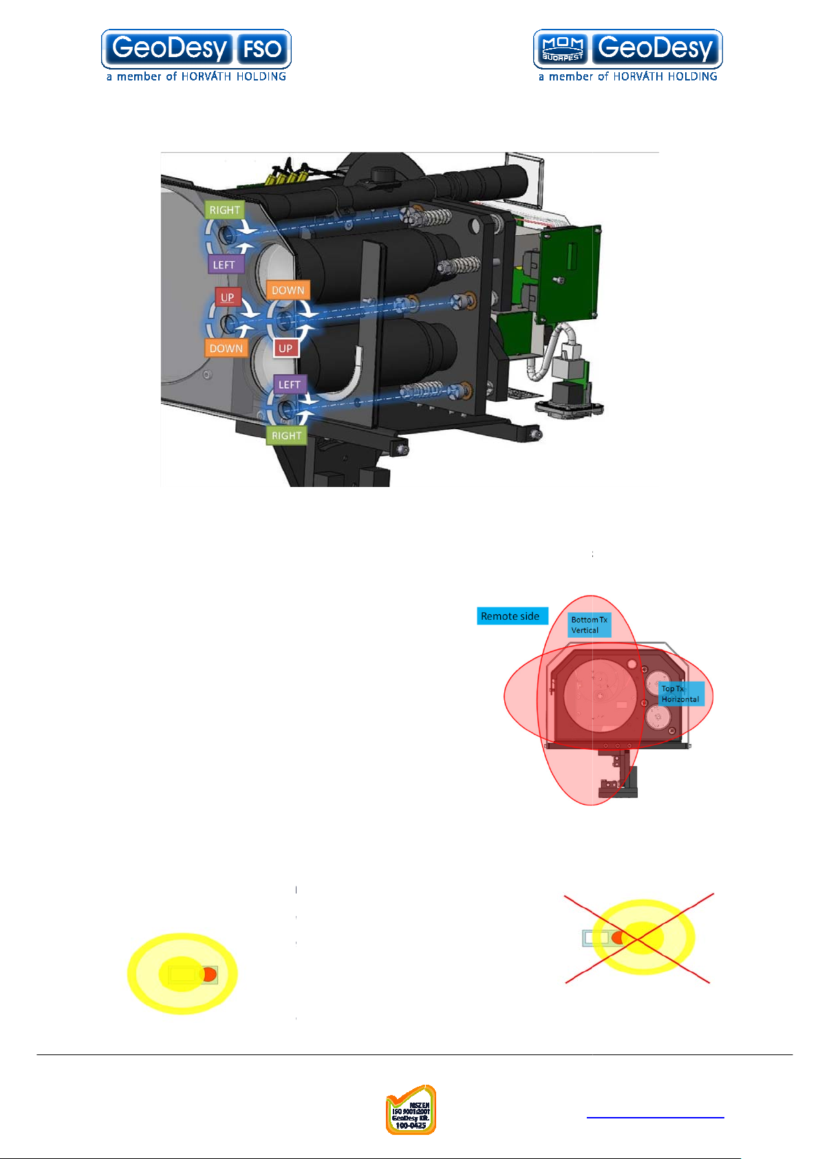
How to use the alignment base
Loose the Coarse locker on the
horizontal as well as on the
vertical side with a 10mm
Move the head left
down you should use the built in
telescope to lit up a few LEDs on
When you have lined the unit up
to a rough position lock the
coarse locker with a 10mm
4 on the remote
On the bottom of the unit you
ine tuning screws one for horizontal and one for vertical.
No tightening is needed on any other screw than the coarse locker.
Telefon: 06
info@geodesy
http://www.
you can see the effect of your local sides
6.1.1 Alignment of the
mo
1.
spanner
2.
received – which is
–
chapter.
- right up
the remote end.
3.
spanner.
4. Repeat step 1-
end.
5.
can find f
6.
GeoDesy Kft.
H-1116 Budapest, Kondorfa str
-8.
E-mail:
16
-1-481-2050
Fax.: 06-1-481-2049
-fso.com
geodesy-fso.com
Page 17

. 6
Site A start moving the
laserhead with the
horizontal fine adjustment
screw by looking at the
received
Using the fine adjustment
screws, lighten as many
2 on Site B.
If necessary try step 1
X setting at the installation site
The installation of the Pronto
the two transmitters can be moved separately. (use only if there is no connection
between the two heads or they need adjustment). During installation the motor
control has to be switched off. It can be switched off by m
Transmitter setting screws can be approached after removing the 4 screws on the
front of the head. See image:
Telefon: 06
info@geodesy
http://www.
above with the only difference that
aking an unfinished
Fine tuning
1.
Remote end
level
2.
LEDs as possible
3. Repeat step 1-
4.
on both sites again.
6.1.2 Pronto-
-2
-X is as described
booting.
GeoDesy Kft.
H-1116 Budapest, Kondorfa str
-8.
Fax.: 06-1-481-2049
E-mail:
17
-1-481-2050
-fso.com
geodesy-fso.com
Page 18
. 6
The transmitters can be moved both in vertical and horizontal directions. See image:
note that we need a minimum 35cm cross screw driver. When the
screws are fitted the transmitters should be covered in the least necessary grade.
The fine adjustment should be done by Geodesy
cause permanent damage, or calibration
Note: Geodesy FSO shall not be responsible for any failures from improper handling
of the device. If any other screw than the coarse lockers or the fine adjustment is
the stability of the installation.
Trick for the reliable alignment
beam has a powerfull ring on the side of the head and easily can be
set to this ring but this is far not as big as the core
part of the beam. So every time you have an
alignment please make sure that when you see the
maximum LED s or a relativly high recei
Keep on moving to determine where the core part of
the beam is. This can be done easily by looking at
the received level you will see that the received level moves up then it will start move
down than up again. During this time you just had the
you have any doubt on how to do the alignment please contact your distributor for further
technical support.
Telefon: 06
info@geodesy
http://www.
head moving into one direction. If
Important to
only. Unauthorized access might
error to the laserhead.
moved, might decrease
Please note that the
-FSO trained engineers
ved level.
help. Or contact GeoDesy FSO
GeoDesy Kft.
H-1116 Budapest, Kondorfa str
-8.
Fax.: 06-1-481-2049
E-mail:
18
-1-481-2050
-fso.com
geodesy-fso.com
Page 19
. 6
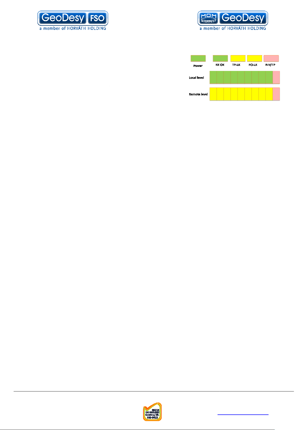
eanings of the LEDs
for communication
the head and the Network
The recived signal form the remote end is modulated and
Remote end is visible for the management system and there is TP connected to
Lk but displays it on the remote end.
Received level
The 10 th LED has three functions showing that the recived level reached its
optimum this is green, it maximum it
Telefon: 06
info@geodesy
http://www.
is yellow or the receiver got saturated and this
6.1.3 M
Power:
The head is powered up.
RX-OK:
Received beam is good
TP Lk:
Copper link between
FO Lk:
R-V/TP:
remote end – same as TP-
Top Level LEDs:
Local Received level
Bottom Level LEDs:
.
equipment.
.
Remote Sites
10th LED:
is red
GeoDesy Kft.
H-1116 Budapest, Kondorfa str
-8.
Fax.: 06-1-481-2049
E-mail:
19
-1-481-2050
-fso.com
geodesy-fso.com
Page 20

. 6
8. Bro
wn
-
VIN
Connecting to your Network
PoE system is connected to the network via one twisted pair
cable. This provides the power and the data for the
PicoX
The unit has connection for the management on the bottom of
the Laser unit.
Please see the connection below.
This is the standard IEEE802.3af connector layout.
Telefon: 06
info@geodesy
http://www.
6.1.4
PoE 802.3 af connection.
FSO
1. Orange/White TX+
2. Orange TX
3. Green/White RX+
4. Blue +VIN
5. Blue/White +VIN
6. Green RX-
7. Brown/White -VIN
GeoDesy
laser head
GeoDesy Kft.
H-1116 Budapest, Kondorfa str
-8.
E-mail:
20
-1-481-2050
Fax.: 06-1-481-2049
-fso.com
geodesy-fso.com
Page 21

. 6
7 Management
monitoring unit is a newly developed highly featured monitoring
manufactured laser links. This high quality equipment
user to monitor the link statuses such as detector voltage transmitter status, and
many other features of the Laser link. Nevertheless, this
usage of this network
laserheads.
a standard feature in the PicoXp and PintoXp systems. For
PicoXs and PintoXs it is an o
purchased, with the invoice number, and the device serial number contact
technical support, for activation code. For further information check Activation
roviding information about
and password
unit arrives with preset values. Such
as user name and password. We strongly recommend
you to change the password after the unit was installed
The default username is admin, and the
admin. If you forget your password contact technical
-
Head information screen
The head information screen is the main navigation panel through this screen you
navigate into the
: displays the name of the device. Individually can be changed
System Uptime: Diplays the
Displays the IP(Internet Protocol) address of the device
displays the managed head type.
Head Serial Number: This is the head serial number and during the Activation
process we will ask for this number.
Telefon: 06
info@geodesy
http://www.
chapter
, and its connection and relationship
ptional and has to be activated. After the activation was
last boot of the device
7.1 Features
The Inband networkfor GeoDesy FSO
describe the
with the GeoDesy FSO
The Monitoring system is
FSO
chapter.
Inband monitoring is p
Login Screen
The GeoDesy FSO
monitoring
allows the
is intended to
GeoDesy
support to receive your fail
will be able to
Device Name
IP address:
unique identifier in the
network.
.
password is
safe password.
submenu, of the monitoring system.
lapsed time from the
which must be a
Managed head:
GeoDesy Kft.
H-1116 Budapest, Kondorfa str
-8.
E-mail:
21
Fax.: 06-1-481-2049
-1-481-2050
-fso.com
geodesy-fso.com
Page 22

. 6
Status info screen
Setup you will enter the main status information screen,
which will give you good summarized information of the device, such as status
information of the transmitters, detector level, or temperature values.
: Transmitter transmitts
nsmitter works properly, transmit
Temperature: ambient temperature inside the device. These units were designed for
extreme conditions and should not have any problems under
some heat so the temperature displayed is not the air temperature
outside the head. For example the temperature can be
1 or
was done device setup. The
shows the local heads received level. In volts, the maximum is 7 volts
and the minimum is 0.2 volts. The value will display error depeding on the setting
Remote Detector level: this value is dispalyed form reception of the remote head.
The maximum is 7 volts and the minimum is 0.2 volts.
TP_Link: displays that there i
displays that there is valid sign
Remote is visible: this status information is a good information about the connection
over the two laserheads if this status is OK that means that there is data transferred
Remote TP Link: shows that whether
and the TP interface is available.
PSU: The PSU of the device is sending the OK signal.
RX OK: this information is showing that the receiver is enabled. It basically means
that there is valid signal with
Telefon: 06
info@geodesy
http://www.
ts and the transmitted signal is valid.
20C to 70C. In fact the
10C outside but in the
2. The value will display error depeding on the setting
re is no default value for this setting, only a suggested
al received from the remote end.
the remote end is connected into the switch
necessary strenght is received in the local end.
Clicking on the Device
Laser ON
Laser OK: Tra
unit is emitting
device it wont go below -
value, which is 60C.
Detector level:
was done device setup.
FSO Link:
-
-
-
s connection over the TP cable.
over the link.
GeoDesy Kft.
H-1116 Budapest, Kondorfa str
-8.
Fax.: 06-1-481-2049
E-mail:
22
-1-481-2050
-fso.com
geodesy-fso.com
Page 23
. 6
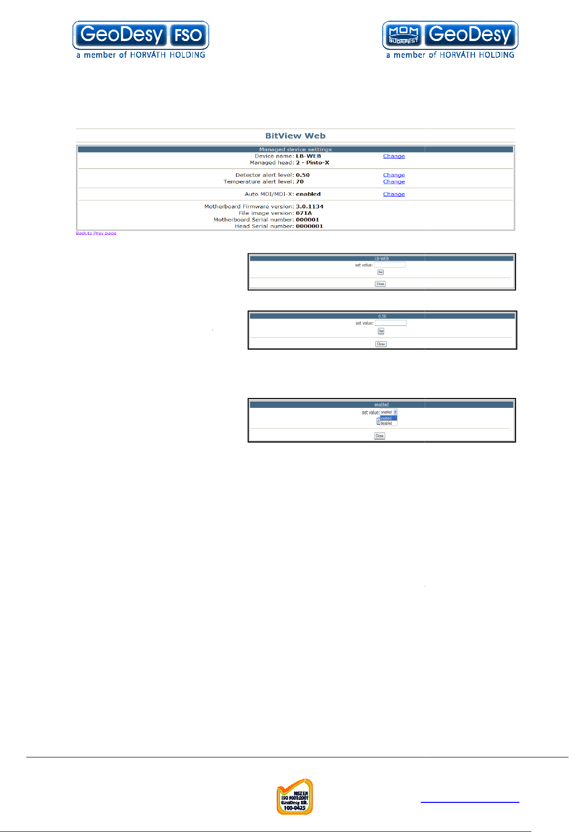
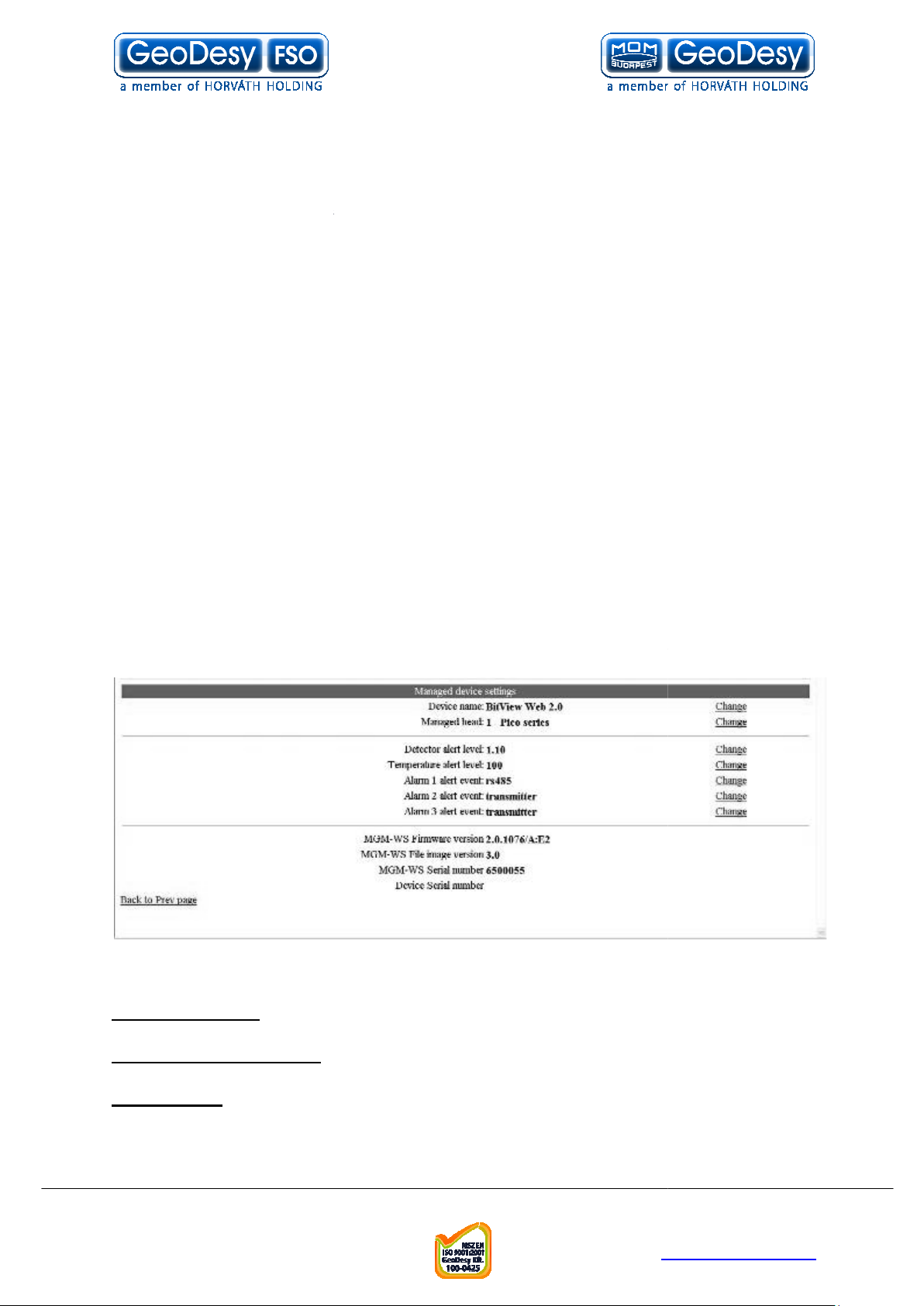
Device setup
The device setup screen leads you to the main monitoring options. Here the alarms
can be set and main information about the Laser head.
uniqe identifier of
Type of the laserhead
when the
received level reach this value,
when the temperature reach this value, the alarm will be
this enables
the Auto setting for the
X, some old switch
types might report
incompatibility here it can be switched off. (Auto MDI/MDI
Motherboard Firmware version:
Version number of the file image
Motherboard Serial number:
as the Head Serial Number)
Serial number of the unit. Should be the same number as the
back of the unit. If the number is missing or not match up with the one on
the back, during activation this is the number you will have to let the support know.
Telefon: 06
info@geodesy
http://www.
X can be turned off even
This is the version number of the Firm
Mainboard serial number inside the head (Not the same
Device name:
the device
Managed head:
Detector alert level:
the alarm will be triggered.
Temperature alert level:
triggered.
Auto MDI/MDI-X:
MDI/MDI-
in the Xs systems)
File image version:
Head Serial number:
one on the
-
ware
GeoDesy Kft.
H-1116 Budapest, Kondorfa str
-8.
E-mail:
23
-1-481-2050
Fax.: 06-1-481-2049
-fso.com
geodesy-fso.com
Page 24
. 6
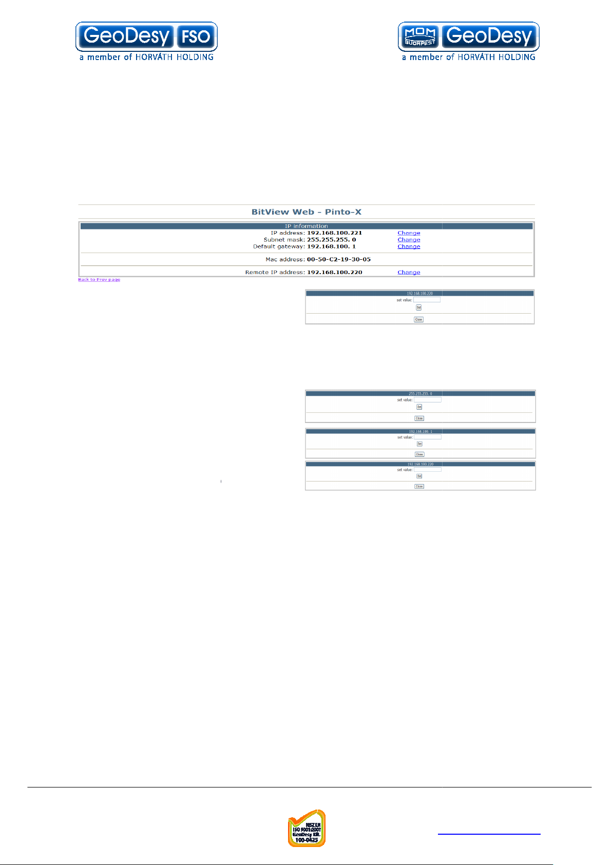
IP Setup
Clicking on the IP Setup link you can have access to the Ethernet module of the
system, this will make easy access to the IP number and/or port settings.
settings are sensitive setting and some of them cannot be restored by the user.
Please always do the changes with extra care! If you have doubt in any step, do not
contact the technical support of the manufacturer website for further
the IP address of the local
device can be set in this box.
address is set retype it to your browser.
Enter only valid IP addresses, if you forget the IP address, you will have to turn to
our support and in some cases return the device for reseting the IP address. Please
always do the IP change with care.
Subnet mask: you can set the subnet
: The default getway
:This will tell this device what
the IP address of the remote device is.
This setting wont change the remote
units IP address, this just identify the remote device f
address is not valid all diplays will go error and the display of the remote sites
received level on the laserhead will be disabled!
Telefon: 06
info@geodesy
http://www.
or the local device. If the IP
hesitate to
information.
Local IP:
If the IP
These
mask of the local device.
Default gateway
setting for the local device.
Remote IP
GeoDesy Kft.
H-1116 Budapest, Kondorfa str
-8.
Fax.: 06-1-481-2049
E-mail:
24
-1-481-2050
-fso.com
geodesy-fso.com
Page 25

. 6
SNMP Setup
One of the main features of the device is the SNMP(Simple Network Monitoring
otocol). The SNMP settings can be set on this page.
Trap address: The IP address of the SNMP trap over the network.
s in the system you have
possibility to setup three different trap
For further details on the trap event see
Trap event list chapter of
: IP address of the
and Read Write
To the setup of the Read
Write community, the
the SNMP agent UDP
port number (11000) the preset value
: the SNMP trap UDP
port number (11000) the preset value
The Laserhead is sending two different traps:
of the alarms will go on (for alarm setting please see chapter 5.4)
(OID:
Telefon: 06
info@geodesy
http://www.
In this section there are the settings of the
1.3.6.1.4.1.17857.0.1201) This trap will be sent after any
1.3.6.1.4.1.17857.0.1202) After the alarm goes off
Pr
Trap event
event.
SNMP Agent.
SNMP trap address
SNMP tarp computer
Read Community
community
and the Readpreset value is public
Agent UDP Port
this book.
is 162
Trap UDP Port
is 161
Traps:
LaserHeadAlarm (OID:
LaserHeadAlarmCancel
this trap will be sent
GeoDesy Kft.
H-1116 Budapest, Kondorfa str
-8.
Fax.: 06-1-481-2049
E-mail:
25
-1-481-2050
-fso.com
geodesy-fso.com
Page 26

. 6
Security
section you can set the username and the password for the unit. If
you have forget the usernam and/or the password please contact The technical
Network statistics page
As a new feature of the Next series of products, you can monitor the li
over the link. These figures are showing the reception on a port of FO(fibre optic
TP(Twisted pair, form the local connected equipment).
sending of information packets to a single destination
is the delivery of information to a group of destinations simultaneously
using the most efficient strategy to deliver the mes
network only once and only create copies when the links to the destinations split.
The word "Multicast" is typically used to refer to
the multicast concept on the IP routing level, where route
tree distribution paths for datagram sent to a multicast destination address in real
time. But there are also other implementations of the multicast distribution strategy
refers to transmitting a packet t
every device on the network. In practice, the scope of the broadcast is limited to a
broadcast domain. Not all computer networks support broadcasting; for example,
neither X.25 nor frame relay supply a broadcast cap
wide broadcast. Broadcasting is largely confined to local area network
(LAN) technologies, most notably Ethernet and Token Ring, where the performance
impact of broadcasting is not as large as it would be in a wid
Ethernet and IPv4 use an all
Fragments: datagram can be fragmented into pieces small enough to pass over a
link with a smaller MTU than the original datagram size.
ssion of a packet on a computer network that is larger than the
network's MTU. Such transmissions hog bandwidth and congest the network. Many
Telefon: 06
info@geodesy
http://www.
sages over each link of the
, the implementation of
rs create optimal spanning
hat will be received (conceptionally) by
ability, nor is there any form of
e area network. Both
ones broadcast address to indicate a broadcast packet.
On the security
support.
ve traffic flows
from the remote end) or
Unicast:
Multicast:
listed below.
Broadcast:
IP Multicast
-
Internet-
-
Jabber: transmi
GeoDesy Kft.
H-1116 Budapest, Kondorfa str
-8.
Fax.: 06-1-481-2049
E-mail:
26
-1-481-2050
-fso.com
geodesy-fso.com
Page 27

. 6
network switches have a built
block it until it resumes pro
per operation.
Decoded package alignment is faulty.
: Coding symbol is missing or faulty.
cyclic redundancy check
a small, fixed number of bits
of network traffic or a block of a computer file. The checksum is used to detect errors
after transmission or storage. A CRC
transmission or storage, and verified afterwards by the recipient to confirm that no
changes occurred on transit. CRCs are popular because they are simple to
implement in binary hardware, are easy to analyze mathematically,
particularly good at detecting common errors caused by noise in transmission
Telefon: 06
info@geodesy
http://www.
in capability to detect when a device is jabbering and
is a type of hash function used to produce a
against a block of data, such as a packet
is computed and appended before
Alignment error:
Symbol error
CRC error:
checksum –
channel.
-
–
and are
GeoDesy Kft.
H-1116 Budapest, Kondorfa str
-8.
Fax.: 06-1-481-2049
E-mail:
27
-1-481-2050
-fso.com
geodesy-fso.com
Page 28
. 6
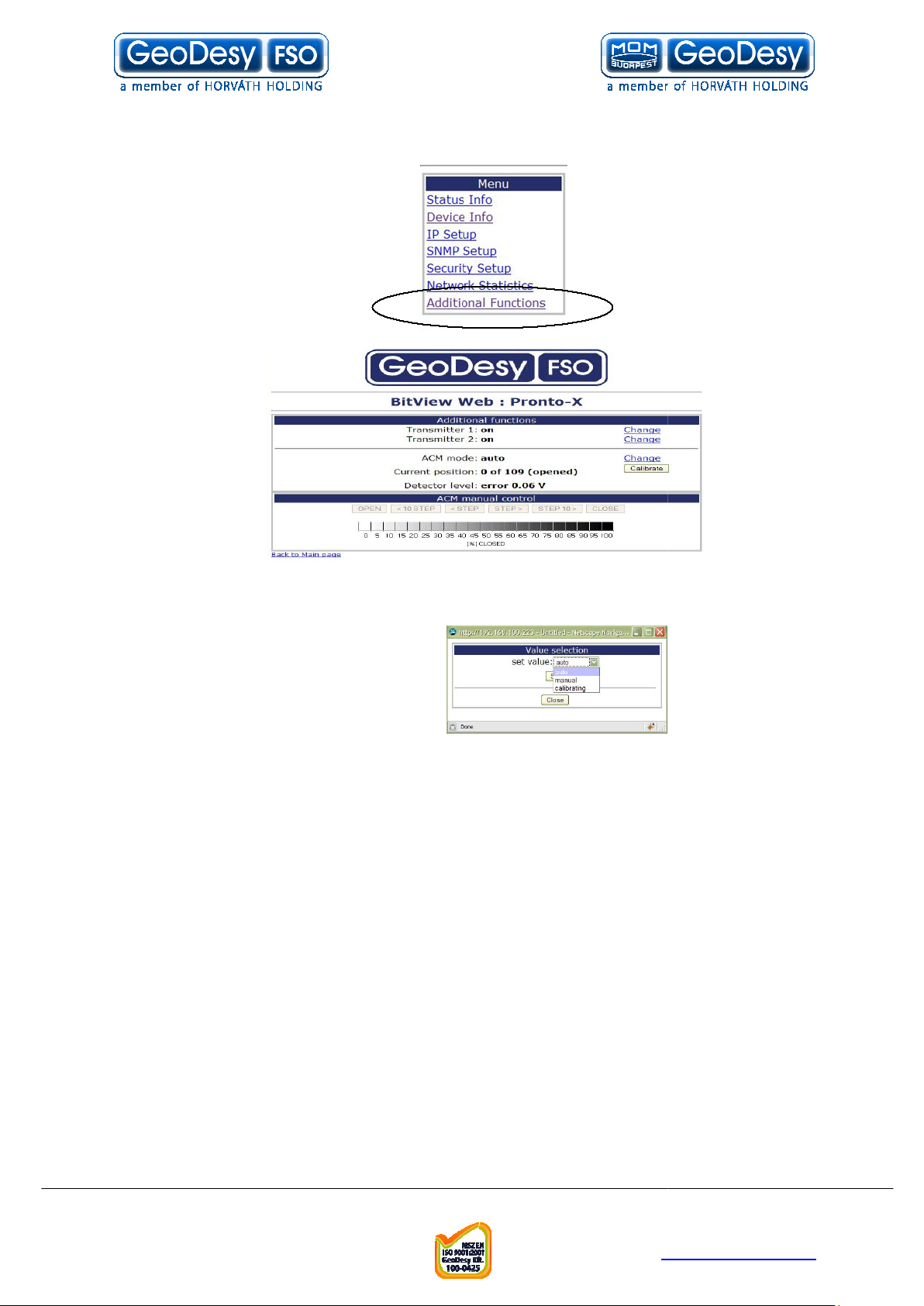
X extra MGM functions
Transmitter on and off: you can switch the transmitters on and off separately
aperture control mechanism
Default: auto mode, the system will automatically regulate the incoming light to the
optimal level of Udet, preventing the system to get oversaturated.
Manual: The incoming light can be regulated manually, the use of the
is strongly suggested during installation. The controller won’t start the regulation of
the incoming light, so the alignment will be much more accurate. (it can be set by
doing an unfinished booting during log in so we do not have to log on to
during the installation process).
Calibrating: it is an extra service. Some silencing settings can be made manually
(according to the scale) and the motor can also be skipped manually via the web. In
order to see where the motor is there are
calibration of the length of the circuit between the two end station in order to see
how many steps are left. Follow
Telefon: 06
info@geodesy
http://www.
cadences. The system has to make a
up calibration can be made with the calibrate button.
Pronto-
Additional functions
ACM: (
.
)
-
GeoDesy Kft.
H-1116 Budapest, Kondorfa str
-8.
Fax.: 06-1-481-2049
E-mail:
28
manual mode
the web
-1-481-2050
-fso.com
geodesy-fso.com
Page 29

. 6
Mandatory Management Activation
buying our product. Please read this note carefully. From software
The product you have bought has fully functional management software, which has
limitation only in time. The unit activation request should be sent to
fso.com
to the email address give, or can be accessed from your local distributor.
After 90 days if the system was not activated the data transmission will be
1. Login to the devices through a web browser
IP:192.168.100.220,192.168.100.221
2. Default login name:admin and password:admin
3. Click on Evaluation period
5. Fill in the table and click on send
6. We will return the activation key
Series(100MB/s) limitation course 1
90 days 1MB/s, beyond 90 days 100KB/s (MGM
Series(1000 MB/s) will be limited after the 90
ill be blocked, except the management system.
Telefon: 06
info@geodesy
http://www.
be issued, later and sent
60 days unlimited, for 61
Option).
day, when the whole
Thank you for
version (3.2.1218/R090x)!
activation@geodesy-
Activation process:
4. Click on Get a key
Limitations:
- All Next10MB/s, for 81-
- All GigaNextbandwidth w
. And the activation code will
degraded!
-
using the
-80 days
-
th
GeoDesy Kft.
H-1116 Budapest, Kondorfa str
-8.
Fax.: 06-1-481-2049
E-mail:
29
-1-481-2050
-fso.com
geodesy-fso.com
Page 30

. 6
Firmware update
The firmware update has the following steps:
Copy Geodesy_FWUpdate_Vxx.xbn over
IP address: the IP address of the device (192.168.100.220 or 192.168.100.221 as a
factory default ) or the IP address you gave to the system earlier
address for the Web management.
er name: same as for the web management (default admin)
Password: same as for the web management (default admin)
If you have passive mode please turn it off, otherwise the system will not connect.
copy the .xbn file over to the Laserhead
Telefon: 06
info@geodesy
http://www.
–
7.2
Run FTP client
Log-in to the Laser-head
Log in the laserhead
Click on update
Wait 50-60 seconds
Restart the laserhead
Run FTP client
FTP client setup
Us
same as the IP
GeoDesy Kft.
H-1116 Budapest, Kondorfa str
-8.
Fax.: 06-1-481-2049
E-mail:
30
-1-481-2050
-fso.com
geodesy-fso.com
Page 31

. 6
Now the Update button will be active
Click on update and the update process will start it takes upto 60 seconds. The
LEDs on the back of the device will go off than lit one after the other.
Make sure that the system power is fixed and
update process. If the LEDs froze, wait 2
cable, and repluging again.
Telefon: 06
info@geodesy
http://www.
the power will not go off during the
3 minutes before unplugging the power
Log off the FTP server
-
GeoDesy Kft.
H-1116 Budapest, Kondorfa str
-8.
Fax.: 06-1-481-2049
E-mail:
31
-1-481-2050
-fso.com
geodesy-fso.com
Page 32
. 6
Reloading factory default settings
Should you need to reload the original factory settings follow the steps
unplug the POE RJ45 cable
replug the POE RJ45 cable
unplug the POE RJ45 cable within 3 seconds
repeat procedure 3 times.
plug the POE RJ45 cable into the system, and leave it plugged in.
After this the system resets the following information to the
NPASD (if avialable)
SNMP
view manual for details how to proceed to this point
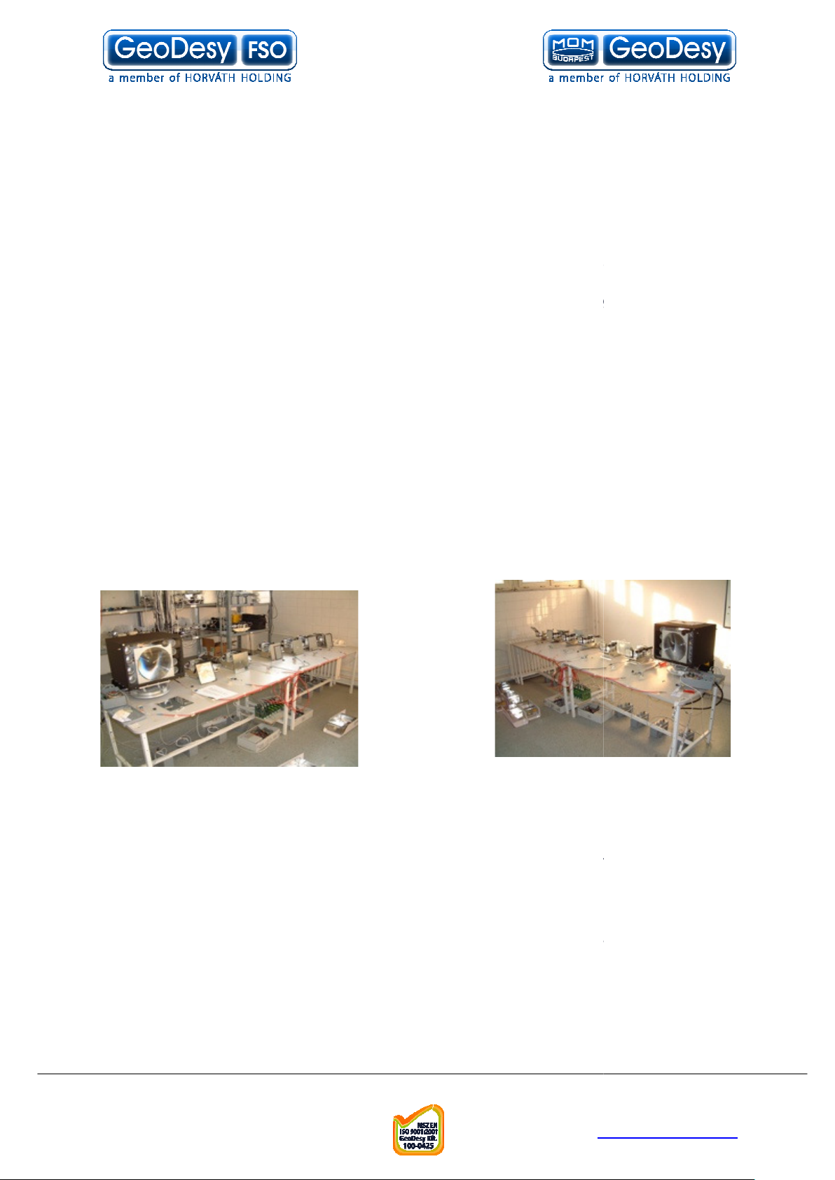
On Figure 1 you can see our test setting. The
of the alarms will go on (for alarm setting please see chapter 5.4)
(OID:
1.3.6.1.4.1.17857.0.1103) This trap is being sent when the
Telefon: 06
info@geodesy
http://www.
factory default.
View is sending 3 traps
1.3.6.1.4.1.17857.0.1201) This trap will be sent after any
1.4.1.17857.0.1202) After the alarm goes off
7.3
1.
2.
3.
4.
5.
- IP address
- Username
- Password
- Device name
- SNMP settings
- Alerts
- Auto MDI/MDIX
-
below.
7.4 Setting up the
Please check the GD
LaserHeadAlarm (OID:
LaserHeadAlarmCancel
this trap will be sent
DeviceDown (OID:
SNMP agent is disabled
1.3.6.
1. Figure
GD-
GeoDesy Kft.
H-1116 Budapest, Kondorfa str
-8.
E-mail:
32
-1-481-2050
Fax.: 06-1-481-2049
-fso.com
geodesy-fso.com
Page 33

. 6
Even if you have one laerhead attached to one
you can generate traps without, causing any problems, with the testing.
For these testing purposes please set Alarm1 to RS485(this will generate traps), and
Alarm2 Alarm3 to transmitter(this wont generate traps, so wont disturb the testing)
On figure 2 the settings can be seen.
Change the Trap address to the MGM console IP address which will have the
Enabled must be set to on the function will disable the SNMP agent.
view is ready to send out the Trap messages, to the Trap
SNMPc Installation
First run snmpc600eval.exe file from the CD.
Run through the setup process by clicking next
Telefon: 06
info@geodesy
http://www.
View, or you are on the live
network
SMNPc installed
After this was set the GD
Addressed PC
7.4.1
GD-
2. Figure
GeoDesy Kft.
H-1116 Budapest, Kondorfa str
-8.
Fax.: 06-1-481-2049
E-mail:
33
-1-481-2050
-fso.com
geodesy-fso.com
Page 34

. 6
After the setup was finished hit OK. Your PC might ask for a restart, in that
Configuration of the SNMPc Management console
Telefon: 06
info@geodesy
http://www.
When the setup asks for the discovery seed
enter you own IP address, Subnet mask a
please restart your PC
SNMPC
7.4.2
community
cases
GeoDesy Kft.
H-1116 Budapest, Kondorfa str
-8.
E-mail:
34
-1-481-2050
Fax.: 06-1-481-2049
-fso.com
geodesy-fso.com
Page 35
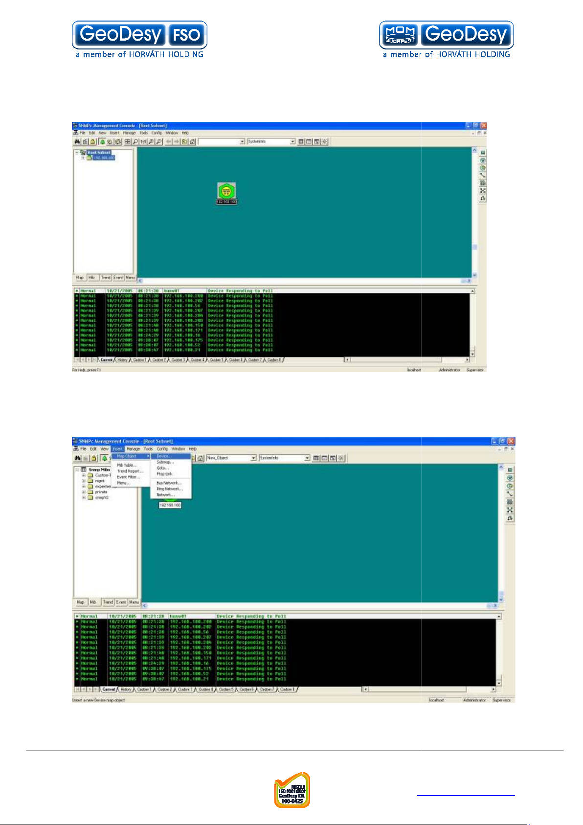
. 6
Programs => SNMPc network manager => Startup system. This
will start the SNMPc Management console. Can be seen on Figure 3
View to the console click on Insert => Map Object => Device. As it is
Telefon: 06
info@geodesy
http://www.
Click on Start =>
To add the GDshown on Figure 4
3. Figure
4. Figure
GeoDesy Kft.
H-1116 Budapest, Kondorfa str
-8.
E-mail:
35
-1-481-2050
Fax.: 06-1-481-2049
-fso.com
geodesy-fso.com
Page 36
. 6
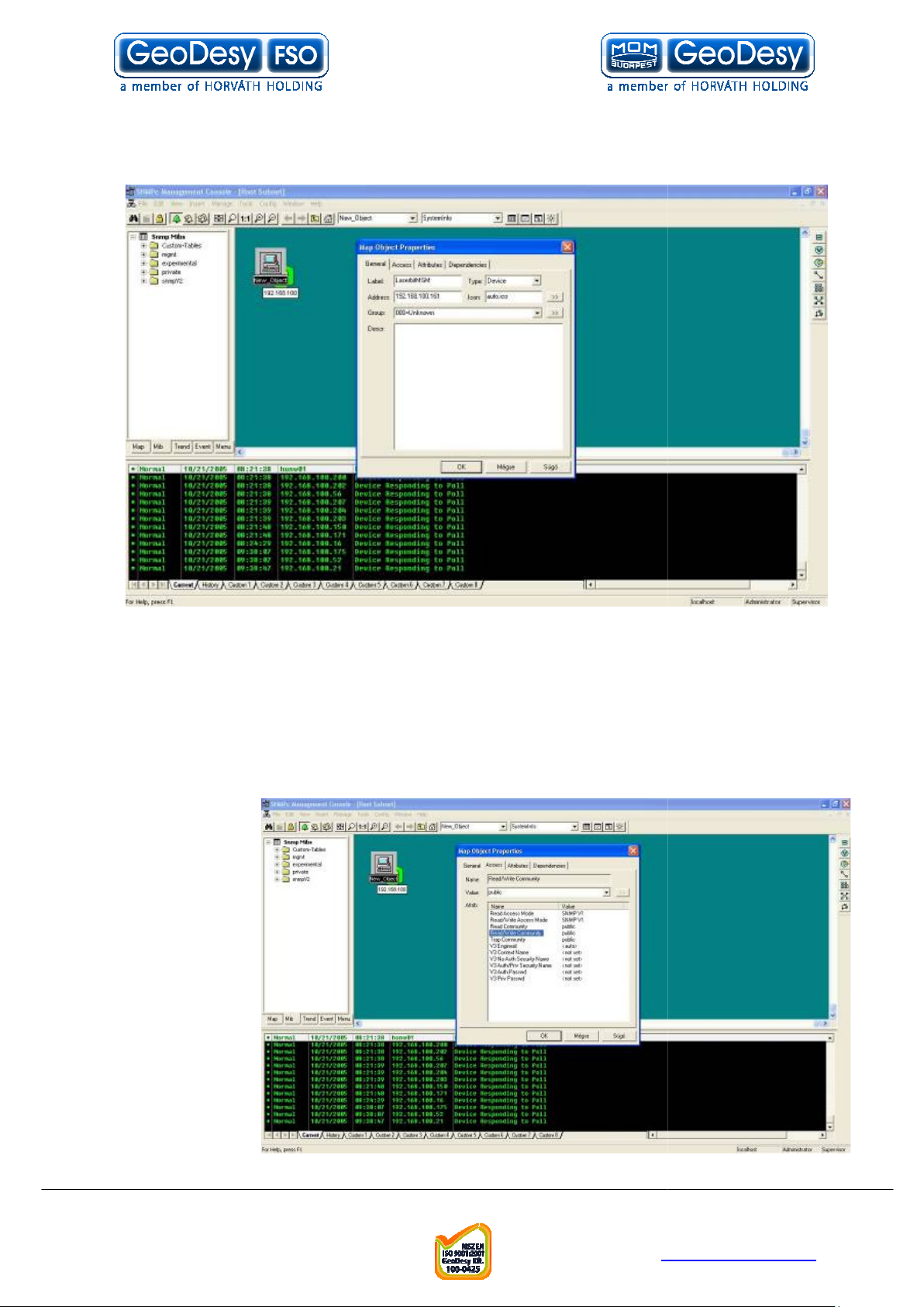
After the Map Onject was added, the properties should be set:
Label : GeoDesy-
FSO MGM (cannot contain spaces, or special caracters) see
Read Access Mode: SNMPV1
de: SNMPV1
Read/Write Community: public
The rest of the setting can be left on factory default.
Telefon: 06
info@geodesy
http://www.
Figure
On the Access Tab
Read/Write Access Mo
Read community: public
Trap community: public
GeoDesy Kft.
H-1116 Budapest, Kondorfa str
-8.
E-mail:
36
-1-481-2050
Fax.: 06-1-481-2049
-fso.com
geodesy-fso.com
Page 37

. 6
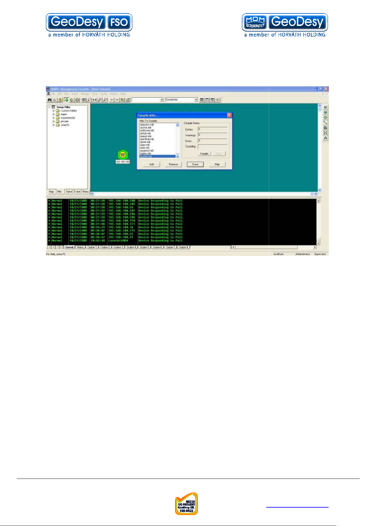
Compiling GeoDesy
First copy the Mib file (GeoDesy
FSO.mib]). Copy this file over to : C:
To Compile the MIB file to the SNMPc Click on Config=>Mib Database
After opening the Mib Database, you should add the MIB file to the Database:
on Add. Add Mib files: find GeoDesy
Telefon: 06
info@geodesy
http://www.
GeoDesy
SNMPc Network
7.4.3
Manager\mibfiles\
-FSO Mib file
-FSO.mib [Source: CD:\Mib\V07\
\Program Files\
-
Click
-FSO.mib, then click OK
GeoDesy Kft.
H-1116 Budapest, Kondorfa str
-8.
E-mail:
37
-1-481-2050
Fax.: 06-1-481-2049
-fso.com
geodesy-fso.com
Page 38
. 6
After you hit OK you have added the Mib file to the database now you will have to
compile it to the management console. So find again GeoDesy
highlight it. Than Hit compile. It wil
Yes.
Telefon: 06
info@geodesy
http://www.
FSO.mib and
l ask you whether you want to compile it click on
-
GeoDesy Kft.
H-1116 Budapest, Kondorfa str
-8.
E-mail:
38
-1-481-2050
Fax.: 06-1-481-2049
-fso.com
geodesy-fso.com
Page 39

. 6
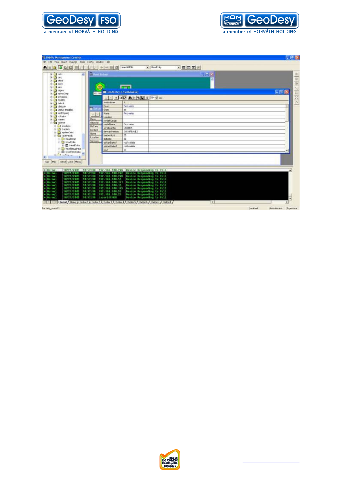
Using SNMP to monitor the link
-
Open mgmt/system/SystemInfo right click on the object and view Table
This table will show you the main Sy
To see the head entries open: private/GeoDesy
Telefon: 06
info@geodesy
http://www.
7.4.4
First click on the GeoDesy
FSO Object to highlight it.
stem information Table:
-FSO/headData
GeoDesy Kft.
H-1116 Budapest, Kondorfa str
-8.
E-mail:
39
-1-481-2050
Fax.: 06-1-481-2049
-fso.com
geodesy-fso.com
Page 40
. 6
Right click on the head entry table and view table.
Now the SNMP is completely set up.
Telefon: 06
info@geodesy
http://www.
GeoDesy Kft.
H-1116 Budapest, Kondorfa str
-8.
E-mail:
40
-1-481-2050
Fax.: 06-1-481-2049
-fso.com
geodesy-fso.com
Page 41

. 6
Generating failure
While the SNMP is working, if you would like to see that actually, it really does what
it suppose to be, unplug the RJ11 (RS485) cable from the
After a few seconds the trap message should arrive to your PC.
After reconnecting the RS485
Telefon: 06
info@geodesy
http://www.
View.
cable the trap message should arrive that the alarm
7.4.5
GD-
was canceled
GeoDesy Kft.
H-1116 Budapest, Kondorfa str
-8.
E-mail:
41
-1-481-2050
Fax.: 06-1-481-2049
-fso.com
geodesy-fso.com
Page 42

. 6
You can acknowledge the alarm with a right click on the alarm.
Telefon: 06
info@geodesy
http://www.
GeoDesy Kft.
H-1116 Budapest, Kondorfa str
-8.
E-mail:
42
-1-481-2050
Fax.: 06-1-481-2049
-fso.com
geodesy-fso.com
Page 43

. 6
SNMP Technology
SNMP is part of the Internet network management architecture. This architecture is
of many entities, as described in the following section.
The Internet Management Model
As specified in Internet RFCs and other documents, a network management system
Sometimes called
hardware devices such as computers, routers, and terminal servers that are
Agents are software modules that reside in network elements. They collect
and store management information such as the number of error packets
A managed object is a characteristic of something that can be
managed. For example, a list of currently active TCP circuits in a particular host
computer is a managed object. Managed objects differ from va
particular object instances. Using our example, an object instance is a single active
TCP circuit in a particular host computer. Managed objects can be scalar (defining a
single object instance) or tabular (defining multiple, related ins
Management information base
residing in a virtual information store. Collections of related managed objects are
defined in specific MIB modules.
A syntax notation is a language used to describe a MIB's
managed objects in a machine
notation allows different types of computers to share information. Internet
management systems use a subset of the Inte
Standardization's (ISO's)
(ASN.1) to define both the packets exchanged by the management
protocol and the objects that are to be managed.
Structure of Management Info
describing management information. The SMI is defined using ASN.1.
Network management stations
execute management applications that monitor and control netw
Physically, NMSs are usually engineering workstation
CPUs, megapixel color displays, substantial memory, and abundant disk space. At
least one NMS must be present in each managed environment.
Newly defined in SNMPv2, a party is a logical SNMPv2 entity that can
initiate or receive SNMPv2 communication. Each SNMPv2 party comprises a single,
unique party identity, a logical network location, a single authentication protocol, and
Telefon: 06
info@geodesy
http://www.
, network elements a
riables, which are
tances).
A MIB is a collection of managed objects
independent format. Consistent use of a syntax
rnational Organization for
(OSI)
The SMI defines the rules for
consoles
caliber computers with fast
7.4.6
based on the interaction
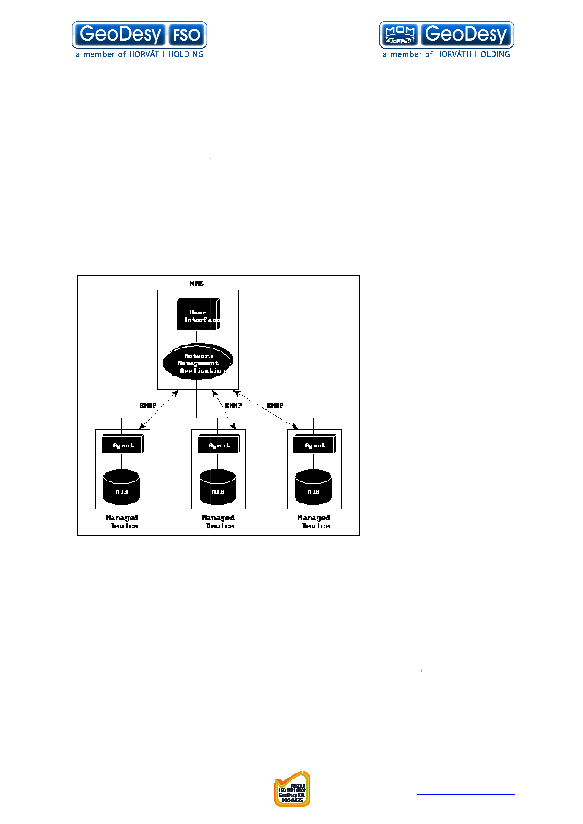
comprises:
Network elements --
connected to networks.
Agents --
a network element.
Managed object --
managed devices
received by
re
Syntax notation --
Notation 1
Parties --
(MIB) --
-
Open System Interconnection
rmation (SMI) --
(NMSs) -- Sometimes called
-
Abstract Syntax
, these devices
ork elements.
GeoDesy Kft.
H-1116 Budapest, Kondorfa str
-8.
Fax.: 06-1-481-2049
E-mail:
43
-1-481-2050
-fso.com
geodesy-fso.com
Page 44
. 6
a single priva
cy protocol. SNMPv2 messages are communicated between two
parties. An SNMPv2 entity can define multiple parties, each with different
parameters. For example, different parties can use different authentication and/or
A management protocol is used to convey management
information between agents and NMSs. SNMP is the Internet community's de facto
standard management protocol.
The most basic elements of the Internet management model are graphically
Figure 1: The Internet Management Model
Interactions between the NMS and managed devices can be any of four different
To monitor managed devices, NMSs read variables maintained by the
rol managed devices, NMSs write variables stored within the
NMSs use these operations to determine which variables a
managed device supports and to sequentially gather information from variable tables
uting tables) in managed devices
Managed devices use traps to asynchronously report certain events to
Telefon: 06
info@geodesy
http://www.
privacy protocols.
Management protocol --
represented in Figure 1.
types of commands:
Reads -devices
Writes -- To cont
managed devices
Traversal operations --
(such as IP ro
Traps -NMSs
GeoDesy Kft.
H-1116 Budapest, Kondorfa str
-8.
Fax.: 06-1-481-2049
E-mail:
44
-1-481-2050
-fso.com
geodesy-fso.com
Page 45

. 6
MIBs and Object Identifiers
A MIB can be depicted as an abstract tree with an unnamed root. Individual data
items make up the leaves of the tree.
name MIB objects in the tree. Object IDs are like telephone numbers
erarchically with specific digits assigned by different organizations.
The object ID structure of an SNMP MIB defines three main branches: Consultative
Committee for International Telegraph and Telephone (CCITT), International
Organization for Standardiza
MIB activity occurs in the portion of the ISO branch defined by object identifier
1.3.6.1 and dedicated to the Internet community.
standard MIB, MIB
objects. These objects are grouped by protocol (including TCP, IP,
[UDP], SNMP, and others) and other categories, including "system" and
The SMI specifies that all managed objects should
is the object ID, which was discussed in the preceding section.
defines the object's data type (for example, "integer" or "string"). A
subset of ASN.1 definitions are used for the SMI syntax. The
how the information associated with the managed object is formatted as a series of
data items for transmission on the network. Another ISO specification, called the
(BERs), details SMI encodings.
e divided into three categories:
simply constructed types
Simple types include four primitive ASN.1 types:
Unique values that are positive or negative whole numbers, including
Unique values that are an ordered sequence of zero or more octets.
Unique values from the set of all object identifiers allocated according
to the rules specified in ASN.1.
New in SNMPv2, these comprise zero or more nam
wide data types refer to special data types defined by the SMI:
Represent an address from a particular protocol family.
negative integers that increment by positive one unt
maximum value, when they are reset to zero. The total number of bytes received on
Telefon: 06
info@geodesy
http://www.
(IDs) uniquely identify or
tion (ISO), and joint ISO/CCITT. Much of the current
II, is defined in RFC 1213 and
have a name, a syntax, and an
encoding
simple types, application
ed bits that specify
organized hi
The current Internet-
Protocol
"interfaces."
SMI Definitions
encoding. The name
The syntax
Object identifiers
-- they are
-
contains 171
User Datagram
describes
Basic Encoding Rules
SMI data types ar
types, and
Integers --
zero.
Octet strings --
Object IDs --
Bit strings --
a value.
Application-
Network addresses -Counters -- Non-
-wide
.
il they reach a
GeoDesy Kft.
H-1116 Budapest, Kondorfa str
-8.
Fax.: 06-1-481-2049
E-mail:
45
-1-481-2050
-fso.com
geodesy-fso.com
Page 46

. 6
an interface is an example of a counter. In SNMPv1, counter size was not specified.
bit counters are defined.
e integers that can increase or decrease, but latch at a
maximum value. The length of an output packet queue (in packets) is an example of
Hundredths of a second since an event. The time since an interface
entered its current state is an example of a tick.
Represents an arbitrary encoding. This data type is used to pass arbitrary
information strings that do not conform to the
Represents signed, integer
the ASN.1 "integer" simple data type, which has arbitrary precision in ASN.1 but
bounded precision in the SMI.
resents unsigned integer
when values are always non
simple data type, which has arbitrary precision in ASN.1 but bounded precision in
s include two ASN.1 types that define multiple objects in
References a row in a table. Each element of the row can be a simple type or
References a table of zero or more rows. Each row has the
Specification of Basic Encoding Rules for ASN.1
BERs. The BERs allow dissimilar machines to exchange management information
by specifying both the position of each bit within the transmitted octe
structure of the bits. Bit structure is conveyed by describing the data type, length,
The SMI for SNMPv2 includes two documents: RFCs 1443 and 1444. RFC 1443
(Textual Conventions) defines the data types used within the MIB modules,
RFC 1444 (Conformance Statements) provides an implementation baseline. The
SNMPv2 SMI also defines two new branches of the Internet MIB tree: security
(1.3.6.1.5) and SNMPv2 (1.3.6.1.6).
SNMP itself is a simple request/response pr
requests without receiving a response. Six SNMP operations are defined:
Allows the NMS to retrieve an object instance from the agent.
Allows the NMS to retrieve the next object instance from a table or lis
within an agent. In SNMPv1, when an NMS wants to retrieve all elements of a table
Telefon: 06
info@geodesy
http://www.
strict data typing used by the SMI.
valued information. This data type redefines
valued information. It is useful
negative. This data type redefines the ASN.1 "integer"
otocol. NMSs can send multiple
In SNMPv2, 32-bit and 64-
Gauges -- Non-negativ
a gauge.
Time ticks --
Opaque --
Integer --
Unsigned integer -- Rep
the SMI.
Simply constructed type
tables and lists:
Row -an application-wide type.
Table -columns.
ISO document 8825 (
-
-
-
same number of
) defines ISO's
and value.
SNMP Operations
Get -GetNext --
GeoDesy Kft.
H-1116 Budapest, Kondorfa str
-8.
Fax.: 06-1-481-2049
E-mail:
46
ts and the
while
t
-1-481-2050
-fso.com
geodesy-fso.com
Page 47

. 6
from an agent, it initiates a Get operation, followed by a series of GetNext
operations.
New for SNMPv2. The GetBulk operation was added to make it easier to
cquire large amounts of related information without initiating repeated get
operations. GetBulk was designed to virtually eliminate the need for GetNext
Allows the NMS to set values for object instances within an agent.
Used by the agent to asynchronously Inform the NMS of some event. The
SNMPv2 trap message is designed to replace the SNMPv1 trap message.
New for SNMPv2. The Inform operation was added to allow one NMS to
send trap information to another.
SNMPv1 messages (packets) contain two parts
. The second part contains the actual SNMP protocol data
unit (PDU) specifying the operation to be performed ("Get," "Set," and so on) and the
ces involved in the operation.
Figure 3: SNMP v1 Message Format
* Trap messages have a slightly different format; for information on this format,
consult the appropriate SNMP specification.
ion field is used to ensure that all network elements are running software
based on the same SNMP version. The community name assigns an access
environment for a set of NMSs using that community name. NMSs within the
community can be said to exist within t
devices that do not know the proper community name are precluded from SNMP
operations, network management personnel also have used the community name as
a weak form of authentication.
The SNMP PDU has the following
Telefon: 06
info@geodesy
http://www.
. The first part contains a
illustrates the SNMPv1 message
he same administrative domain. Because
GetBulk -a
operations.
Set -Trap --
Inform --
and a community name
-next
1
version
object instan
format.
The vers
Figure 3
fields:
GeoDesy Kft.
H-1116 Budapest, Kondorfa str
-8.
Fax.: 06-1-481-2049
E-mail:
47
-1-481-2050
-fso.com
geodesy-fso.com
Page 48

. 6
Specifies the type of PDU being transmitted.
Associates requests with responses.
Indicates an error and an error type. In SNMPv2 GetBulk operations,
this field becomes a NonRepeaters field. For these op
ed variables listed that should be retrieved no more than once
from the beginning of the request. The field is used when some of the variables are
scalar objects with only one variable.
sociates the error with a particular object instance. In SNMPv2
GetBulk operations, this field becomes a Max Repetitions field. For these operations,
this field defines the maximum number of times that other variables beyond those
specified by the NonRepea
Comprises the data of an SNMP PDU. Variable bindings
associate particular object instances with their current values.
Like SNMPv1 messages, SNMPv2 messages (shown in
The second part of the SNMPv2 message (the PDU) is virtually identical to that of an
SNMPv1 message (see the previous description of an SNMP PDU for differences).
The first part of the SNMPv2 message contains the majority of the differ
between SNMPv1 and SNMPv2.
Figure 4: SNMP v2 Message Format
SNMPv2 message is often called a
authentication and privacy information in the form of destination and source parties.
lier, a party includes the specification of both an authentication and
a privacy protocol. In addition to a destination and a source party, the wrapper
. A context specifies the managed objects visible to an operation.
protocol is designed to reliably identify the integrity of the
originating SNMPv2 party. It consists of authentication information required to
support the authentication protocol used. The privacy protocol is designed to protect
information within the SNM
messages can be protected from disclosure. In other words, authentication is
The SNMPv2 specifications discuss two primary security protocols: one for
authentication and one for privac
Symmetric Privacy Protocol.
Telefon: 06
info@geodesy
http://www.
erations, this field defines the
) contain two parts.
. The wrapper includes
Pv2 message from disclosure. Only authenticated
Digest Authentication Protocol
PDU type -Request-ID -Error-status --
number of request-
Error-index -- As
Variable-bindings --
ters field should be retrieved.
Figure 4
ences
The first part of a
wrapper
As mentioned ear
includes a context
The authentication
required for privacy.
y. These are the
the
GeoDesy Kft.
H-1116 Budapest, Kondorfa str
-8.
Fax.: 06-1-481-2049
E-mail:
48
and
-1-481-2050
-fso.com
geodesy-fso.com
Page 49

. 6
The Digest Authentication Protocol verifies that the message received is the same
one that was sent. Data integrity is protected using a 128
calculated according to the Message Digest 5 (MD5) algorithm. The digest is
calculated at the sender and enclosed with the SNMPv2 message. The receiver
verifies the digest. A secret value, known only to the sender and the receiver, is
age. After the digest is used to verify message integrity, the
secret value is used to verify the message's origin.
To help ensure message privacy, the Symmetric Privacy Protocol uses a secret
encryption key known only to the sender and the receiver. Bef
authenticated, this protocol uses the
effect privacy. DES is a documented
American National Standards Institute
inally, SNMPv1 specified that SNMP should operate over the
(UDP) and IP. The SNMPv2 transport mapping document (RFC 1449)
defines implementations of SNMP over other transport protocols, including
Connectionless Network Service
Internet Packet Exchange
instructions on how to provide a SNMPv1 proxy and use of the BER. UDP/IP is still
SNMPv2's preferred transport mapping because UDP is
both the transport and network layers.
Telefon: 06
info@geodesy
http://www.
bit
ore the message is
(DES) algorithm to
National Institute of Standards and Technology
(ANSI) standard.
Datagram Delivery Protocol
(IPX). RFC 1449 also includes
compatible with SNMPv1 at
prefixed to the mess
(NIST) and
Orig
Protocol
(DDP), and Novell's
Data Encryption Standard
(CLNS), AppleTalk's
-
message digest
User Datagram
OSI
GeoDesy Kft.
H-1116 Budapest, Kondorfa str
-8.
Fax.: 06-1-481-2049
E-mail:
49
-1-481-2050
-fso.com
geodesy-fso.com
Page 50

. 6
Trap event list
Alert disabled: there is no alert coming up for this trap
Temperature: The agent will send an alarm if the value goes above the preset value.
For further details please see
The agent will send an alarm if the value goes above the preset value. For
Detector alert level in the
Transmitter: if the transmitter fails
Power supply: if the power supply reports fault the agent will send the alarm.
Receiver: If the receiver gets into disabled the agent will send an alarm.
in the
Remote Failure: If the local head loses the connetion to the remote head the agent
will send an alarm. For further details please see
FSO Link:The Agent will send an alarm if the valid signal is
in the
TP Link: The Agent will send an alarm if the connection is lost on the local TP port.
For further details please see
error: The agent will send an alarm if any of the values on the
is incremented.
Telefon: 06
info@geodesy
http://www.
Device Setup
chapter.
operating the agent will send an alarm.
Remote is visible
. For further details
chapter.
Detector:
further details please see
details please see RX OK
info screen chapter
please see FSO Link
Traffic
statistics page
Temperature alert level in the
Device Setup
Status info screen chapter
Status info screen chapter.
TP_Link in the Status info screen
chapter.
For further
in the Status
lost.
Network
GeoDesy Kft.
H-1116 Budapest, Kondorfa str
-8.
Fax.: 06-1-481-2049
E-mail:
50
-1-481-2050
-fso.com
geodesy-fso.com
Page 51

. 6
Warranty conditions
(Europe) LTD
purchased will free from defects in material and workmanship for a period of one (1)
year from the date of purchase. This warranty period will not be extended by virtue
of a repair of the product or a replacement of any component of the product du
This warranty covers only normal commercial use.
is not responsible for warranty service should the
identification marks, serial numbers or original seals be removed, altered, or broken,
ould the product fail to be properly maintained or fail to function properly as a
result of any modification, misuse, abuse, improper installation, neglect, improper
shipping, damage caused by disasters such as fire, flood, earthquake or lightning,
r electrical current, or service other than by
or its authorised partners.
product fails to operate as warranted at any time during the
GeoDesy FSO
replace the defective product at no additional charge.
GeoDesy FSO
including loss of data, lost profits, lost savings, lost business, or other incidental or
ial or indirect damages arising out of the installation, use, maintenance,
performance, failure or interruption of the
(Europe) LTD
GeoDesy F
not allow the limitation or exclusion of liability for incidental or consequential
damages, so the above limitation may not apply to you.
The purchaser or user shall have the responsibility to give
prompt written notice of any warranty claims. If the product was
purchased through an authorised partner of
notice may be given in writing to that authorised partner in the area in which the
The product may be returned to
Return Material Authorisation (RMA) number. The product must be shipped prepaid,
insured and in the original shipping package or similar package for safe shipment.
st be marked on the outside of the shipping package. Any
product returned without an RMA number shall be rejected.
Transportation charges for the return of the product will be paid by
if it is determined by
Telefon: 06
info@geodesy
http://www.
GeoDesy FSO
GeoDesy FSO
GeoDesy FSO
GeoDesy FSO
will repair, or at its option,
be liable for any damages
product, even if
has been advised of the possibility of such damage.
product in the United States, some states do
GeoDesy F
(Europe) LTD
(Europe) LTD
GeoDesy FSO
(Europe)
8
GeoDesy FSO
the warranty period.
LTD
or sh
imprope
LTD
If the
warranty period,
In no event will
GeoDesy FSO
warrants that the
(Europe) LTD
(Europe) LTD
product
ring
(Europe)
(Europe)
consequent
GeoDesy FSO
If you purchased the
(Europe) LTD
product was being used.
The RMA number mu
(Europe) LTD
SO
GeoDesy FSO
GeoDesy FSO
GeoDesy FSO
GeoDesy FSO
only if it has a
LTD
that the
SO
,
GeoDesy Kft.
H-1116 Budapest, Kondorfa str
-8.
Fax.: 06-1-481-2049
E-mail:
51
-1-481-2050
-fso.com
geodesy-fso.com
Page 52

. 6
product was defective within the terms of the warranty; otherwise the purchaser or
user shall be responsible for costs of return handling and transportation.
If the
emedy shall be repair or replacement. The foregoing warranties
and remedies are exclusive and are in lieu of all other warranties, expressed or
implied, either in fact or by operation of law, statutory or otherwise, including
warranties of merchantability
neither assumes nor authorises any other person to assume for it any other liability
in connection with the sale, installation, use or maintenance of the product.
Privacy statement
ll, or rent individual personal information with anyone without
your advance permission or unless ordered by a court of law. Information submitted
to us is only available to employees managing this information for purposes of
contacting you or sending you
contracted service providers for purposes of providing services relating to our
Telefon: 06
info@geodesy
http://www.
product does not operate as warranted above, the
GeoDesy FSO
emails based on your request for information and to
customer’s sole r
GeoDesy FSO
9
We will never share, se
communications with you.
and fitness for a particular purpose.
GeoDesy Kft.
H-1116 Budapest, Kondorfa str
-8.
Fax.: 06-1-481-2049
E-mail:
52
-1-481-2050
-fso.com
geodesy-fso.com
 Loading...