

Page 1
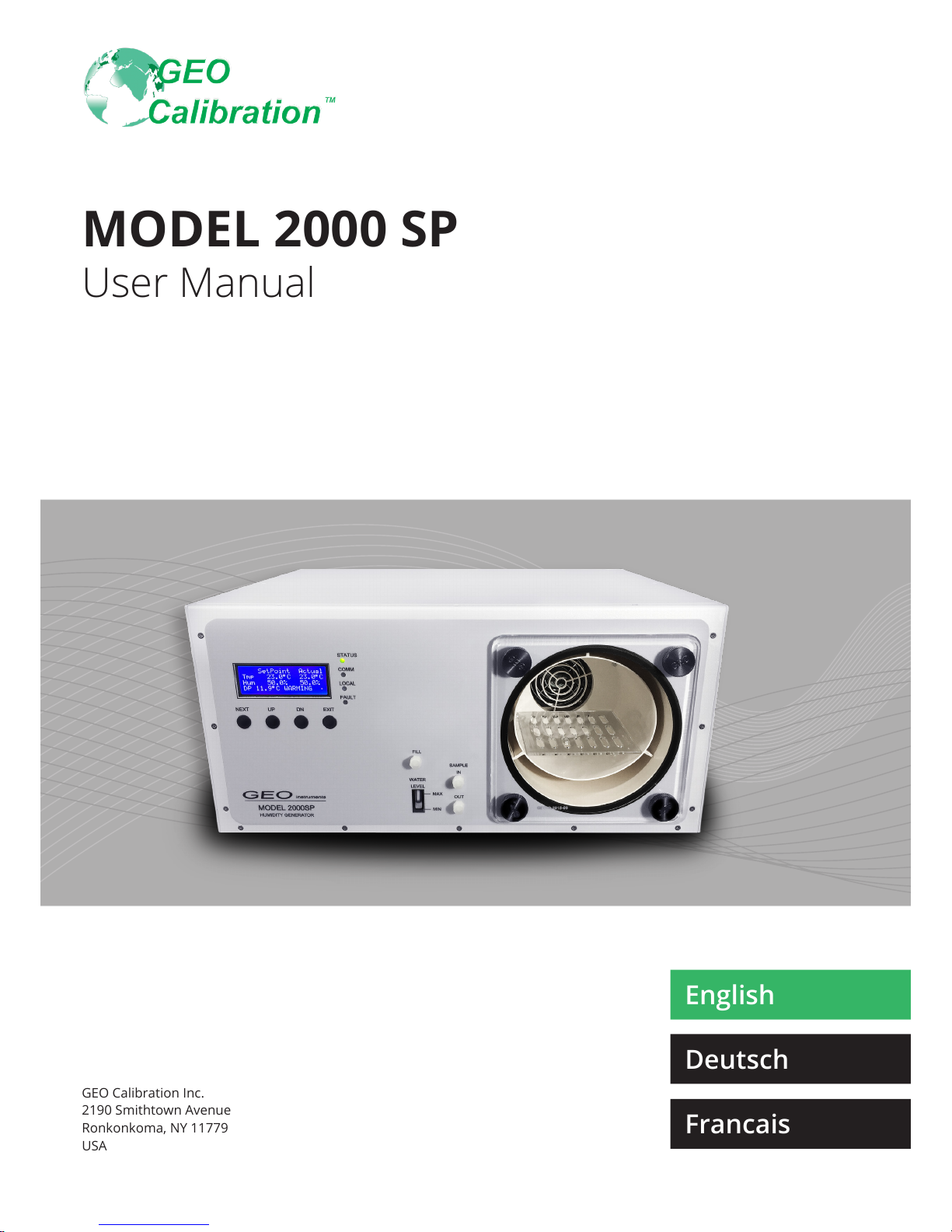
MODEL 2000 SP
GEO Calibration Inc.
2190 Smithtown Avenue
Ronkonkoma, NY 11779
USA
User Manual
English
Deutsch
Francais
Page 2

2
STANDARD PACKAGE LISTING
• GEO Calibration Model 2000 SP Humidity Generator / Calibrator
• 1 Model 2000 SP desiccant cell lled with indicating molecular sieve (pre-installed)
• Power Cable
• Water Fill Syringe
• Capacitive Control Probe with calibration certicate
• Chamber Door (Per customer order)
• USB A to A cable
• USB Stick containing the following:
• GEO Model 2000 SP Product Manual
• GEO Software Manual
• GEO RH Automatic Ramp / Soak Software
• Model 2000 SP Drivers for Windows
Contents of the Standard Supply Package
Page 3

3
LIMITED WARRANTY AND LIMITATION OF LIABILITY
Each GEO Calibration product is warranted to be free from defects in material and workmanship under
normal use and service. The warranty period is one year and begins on the date of shipment. Parts,
product repairs, and services are warranted for 90 days. This warranty extends only to the original
buyer or end-user customer of a GEO Calibration authorized reseller, and does not apply to fuses, dis-
posable batteries, or to any product which, in GEO Calibration’s opinion, has been misused, altered,
neglected, contaminated, or damaged by accident or abnormal conditions of operation or handling.
GEO Calibration does not warrant that software will be error free or operate without interruption.
GEO Calibration authorized resellers shall extend this warranty on new and unused products to end-user customers only but have no authority to extend a greater or different warranty on behalf of GEO
Calibration. Warranty support is available only if product is registered at
https://www.geocalibration.com/register
and is purchased through a GEO Calibration authorized sales outlet or Buyer has paid the applicable
international price. GEO Calibration reserves the right to invoice Buyer for importation costs of repair/
replacement parts when product purchased in one country is submitted for repair in another country.
GEO Calibration’s warranty obligation is limited, at GEO Calibration’s option, to refund of the purchase
price, free of charge repair, or replacement of a defective product which is returned to a GEO Calibration authorized service center within the warranty period.
To obtain warranty service, contact your nearest GEO Calibration authorized service center to obtain
return authorization information, then send the product to that service center, with a description of the
difculty, postage and insurance prepaid (FOB Destination). GEO Calibration assumes no risk for damage in transit. Following warranty repair, the product will be returned to Buyer, transportation prepaid
(FOB Destination). If GEO Calibration determines that failure was caused by neglect, misuse, con-
tamination, alteration, accident, or abnormal condition of operation or handling, including over voltage
failures caused by use outside the product’s specied rating, or normal wear and tear of mechanical
components, GEO Calibration will provide an estimate of repair costs and obtain authorization before
commencing the work. Following repair, the product will be returned to the Buyer transportation prepaid and the Buyer will be billed for the repair and return transportation charges (FOB Shipping Point).
THIS WARRANTY IS BUYER’S SOLE AND EXCLUSIVE REMEDY AND IS IN LIEU OF ALL OTHER
WARRANTIES, EXPRESS OR IMPLIED, INCLUDING BUT NOT LIMITED TO ANY IMPLIED WARRANTY OF MERCHANTABILITY OR FITNESS FOR A PARTICULAR PURPOSE. GEO CALIBRATION SHALL NOT BE LIABLE FOR ANY SPECIAL, INDIRECT, INCIDENTAL, OR CONSEQUENTIAL
DAMAGES OR LOSSES, INCLUDING LOSS OF DATA, ARISING FROM ANY CAUSE OR THEORY.
Since some countries or states do not allow limitation of the term of an implied warranty, or exclusion
or limitation of incidental or consequential damages, the limitations and exclusions of this warranty may
not apply to every buyer. If any provision of this Warranty is held invalid or unenforceable by a court or
other decision-maker of competent jurisdiction, such holding will not affect the validity or enforceability
of any other provision.
GEO Calibration Inc.
2190 Smithtown Avenue
Ronkonkoma, NY, 11779
U.S.A.
WARRANTY
Page 4
4
INTRODUCTION
Thank you!
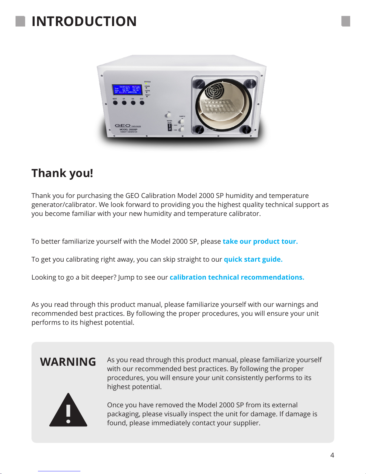
Thank you for purchasing the GEO Calibration Model 2000 SP humidity and temperature
generator/calibrator. We look forward to providing you the highest quality technical support as
you become familiar with your new humidity and temperature calibrator.
To better familiarize yourself with the Model 2000 SP, please take our product tour.
To get you calibrating right away, you can skip straight to our quick start guide.
Looking to go a bit deeper? Jump to see our calibration technical recommendations.
As you read through this product manual, please familiarize yourself with our warnings and
recommended best practices. By following the proper procedures, you will ensure your unit
performs to its highest potential.
WARNING
As you read through this product manual, please familiarize yourself
with our recommended best practices. By following the proper
procedures, you will ensure your unit consistently performs to its
highest potential.
Once you have removed the Model 2000 SP from its external
packaging, please visually inspect the unit for damage. If damage is
found, please immediately contact your supplier.
Page 5

5
PRODUCT OVERVIEW
Calibrator Applications
Once you have removed the Model 2000 SP from its external packaging, please visually inspect
the unit for damage. If damage is found, please immediately contact your supplier.
The GEO Model 2000 SP Humidity Calibrator generates and maintains a controlled humidity and
temperature environment for the purpose of testing or calibrating humidity and temperature
sensors, also known as hygrometers. The humidity calibration range is 5% up to 95%, while the
temperature range is from 5°C to 55°C.
The system’s accuracy is achieved via a NIST traceable internal control and reference probe.
The Model 2000 SP can calibrate many hygrometer types, including but not limited to:
• Probes
• Data-loggers
• Chart Recorders
• Additional Assorted Hygrometers
Before purchasing a Model 2000 SP, please review the dimensions of the calibration chamber to
ensure compatibility with the size requirements of any Hygrometers you intend to calibrate.
Page 6
USB Cable
(A to A)
6
6
ITEM CHECK LIST
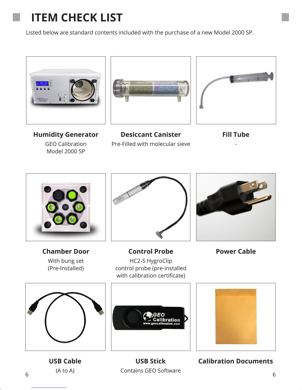
Listed below are standard contents included with the purchase of a new Model 2000 SP.
Humidity Generator Desiccant Canister
Control Probe
USB Stick
Fill Tube
Power Cable
Calibration Documents
GEO Calibration
Model 2000 SP
Pre-Filled with molecular sieve
HC2-S HygroClip
control probe (pre-installed
with calibration certicate)
Contains GEO Software
-
Chamber Door
With bung set
(Pre-Installed)
Page 7

7
ACCESSORIES
Replacement
Desiccant
P/N: 3-DEC
System
Recalibration
P/N: RHG-A-CAL
Door Variations
Replacement
Fill Tube
P/N: RHG-A-FT
Replacement
Control Sensor
P/N: RHG-A-SCP
Silicone
Adapter Kits
P/N: RHG-A-BNG
Page 8

8
UNIT DIAGRAM & PARTS LISTING
Below you will nd a diagram of the Model 2000 SP’s various operational parts.
FRONT
REAR
Status Indicator
Comm Indicator
Local Indicator
Fault Indicator
LCD Display
Desiccant
“NEXT”
“UP”
Button
Button
Button
Button“DOWN”
“EXIT”
Door Screw
Sample OUT
Probe Port
Water Fill Level
Sample IN
Fill Port
Cooling Fan
Carry Handle
Ground
12 V DC Power
Mains Power
Power Switch
Analog RH Out
USB Interface
Fuse
Drain Plug
Analog Temp out
Page 9
9
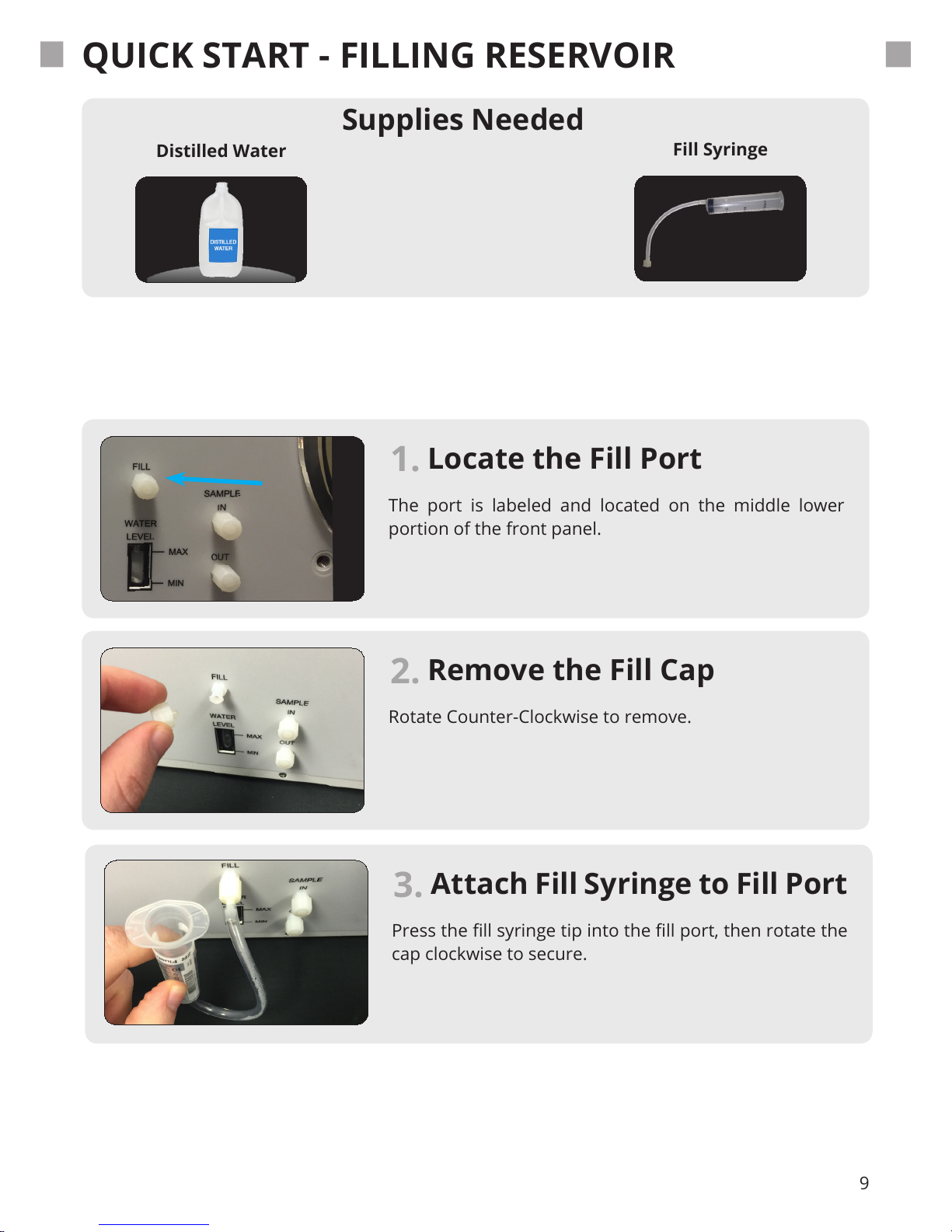
Locate the Fill Port
The port is labeled and located on the middle lower
portion of the front panel.
Attach Fill Syringe to Fill Port
Press the ll syringe tip into the ll port, then rotate the
cap clockwise to secure.
3.
1.
Remove the Fill Cap
Rotate Counter-Clockwise to remove.
2.
QUICK START - FILLING RESERVOIR
Supplies Needed
Distilled Water
Fill Syringe
Page 10
10
QUICK START - FILLING RESERVOIR
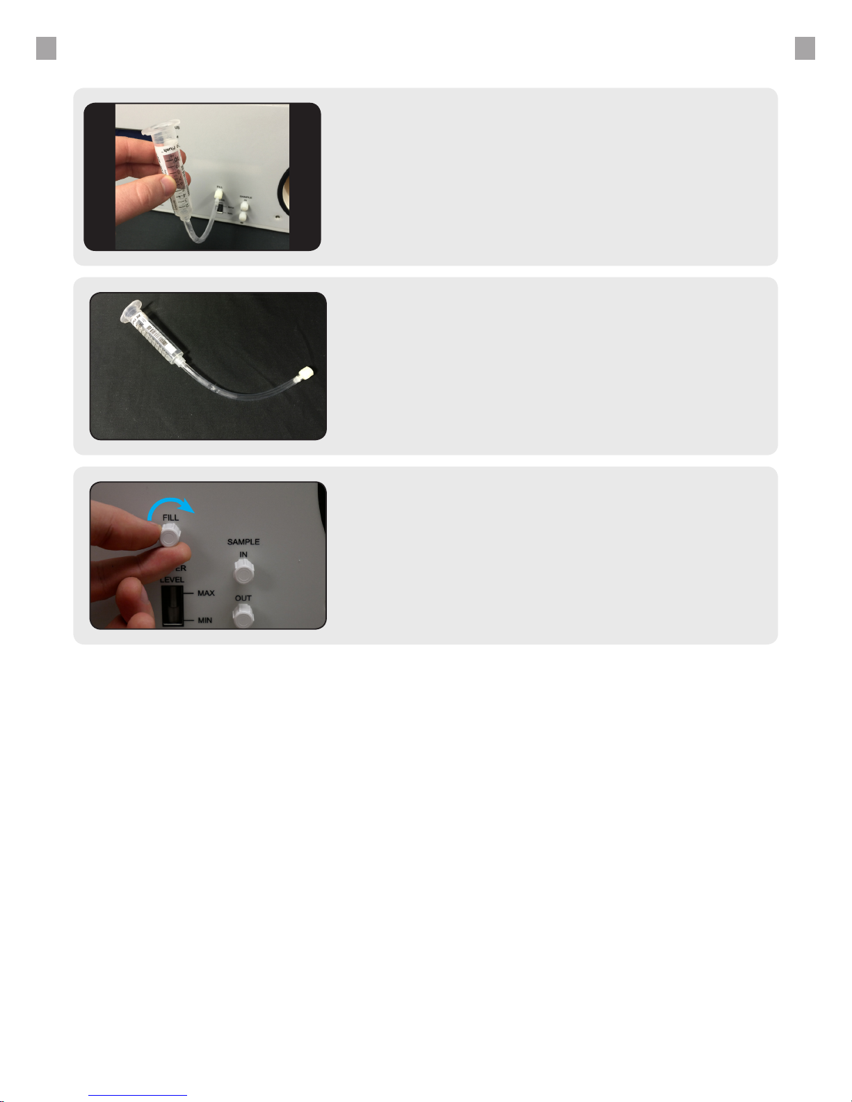
- Pour distilled water into the elevated tube body.
- Take care not to insert any air into the reservoir.
- Monitor the water level indicator while lling.
5.
Loosen and Remove Syringe
Turn the ll syringe tip counter-clockwise to loosen.
6.
Re-Install the Fill Cap
Turn the cap clockwise to tighten the cap and seal the
ll port.
7.
Elevate and Fill Syringe
Page 11

11
QUICK START - POWERING THE UNIT
Locate the Power Input
1.
Set Power Switch to “ON”
4.
Plug Power Supply into Unit
3.
Plug Power Supply into Wall
2.
Supplies Needed
Power Supply
Cable
Page 12

12
QUICK START - UNIT OPERATION
Boot Screen
Our Company Name
Model Number
Serial Number
Firmware Version Number
1.
Page 13
13
QUICK START - UNIT OPERATION
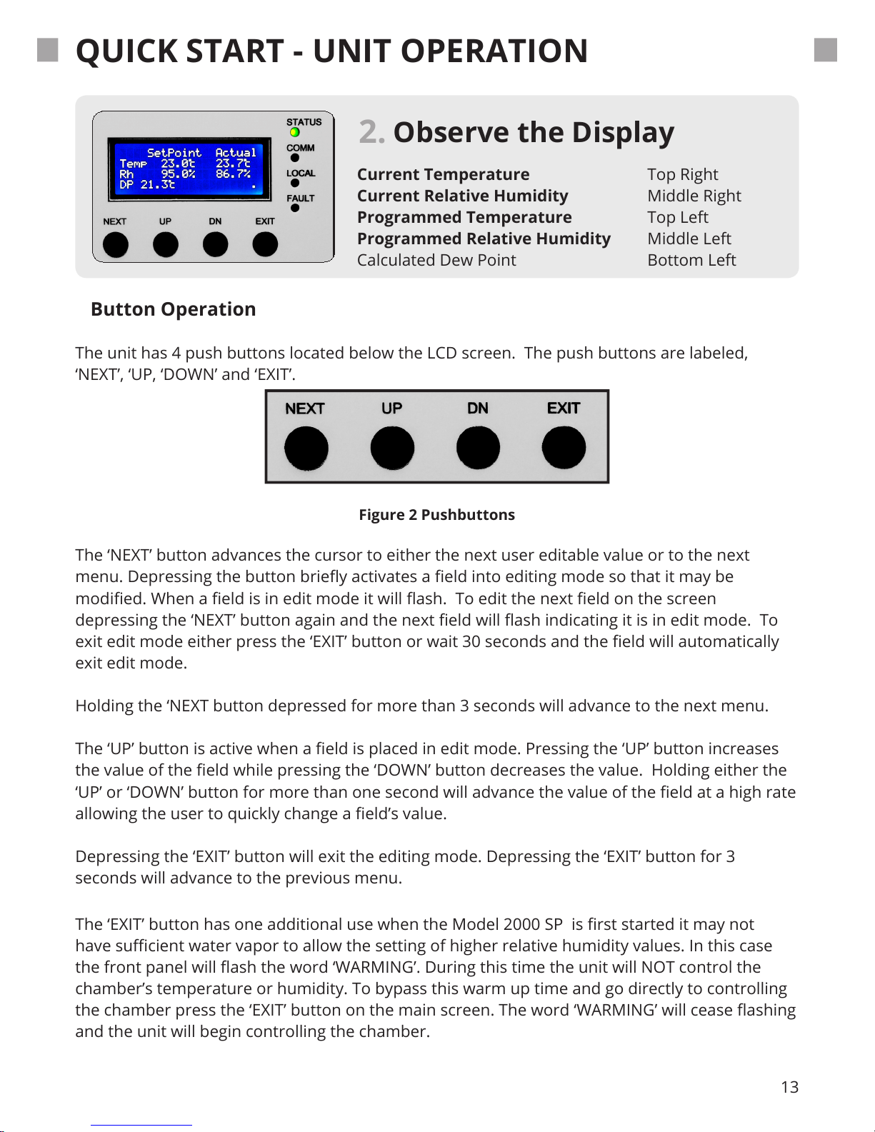
Observe the Display
Current Temperature Top Right
Current Relative Humidity Middle Right
Programmed Temperature Top Left
Programmed Relative Humidity Middle Left
Calculated Dew Point Bottom Left
2.
Figure 2 Pushbuttons
Button Operation
The unit has 4 push buttons located below the LCD screen. The push buttons are labeled,
‘NEXT’, ‘UP, ‘DOWN’ and ‘EXIT’.
The ‘EXIT’ button has one additional use when the Model 2000 SP is rst started it may not
have sucient water vapor to allow the setting of higher relative humidity values. In this case
the front panel will ash the word ‘WARMING’. During this time the unit will NOT control the
chamber’s temperature or humidity. To bypass this warm up time and go directly to controlling
the chamber press the ‘EXIT’ button on the main screen. The word ‘WARMING’ will cease ashing
and the unit will begin controlling the chamber.
The ‘NEXT’ button advances the cursor to either the next user editable value or to the next
menu. Depressing the button briey activates a eld into editing mode so that it may be
modied. When a eld is in edit mode it will ash. To edit the next eld on the screen
depressing the ‘NEXT’ button again and the next eld will ash indicating it is in edit mode. To
exit edit mode either press the ‘EXIT’ button or wait 30 seconds and the eld will automatically
exit edit mode.
Holding the ‘NEXT button depressed for more than 3 seconds will advance to the next menu.
The ‘UP’ button is active when a eld is placed in edit mode. Pressing the ‘UP’ button increases
the value of the eld while pressing the ‘DOWN’ button decreases the value. Holding either the
‘UP’ or ‘DOWN’ button for more than one second will advance the value of the eld at a high rate
allowing the user to quickly change a eld’s value.
Depressing the ‘EXIT’ button will exit the editing mode. Depressing the ‘EXIT’ button for 3
seconds will advance to the previous menu.
Page 14
14
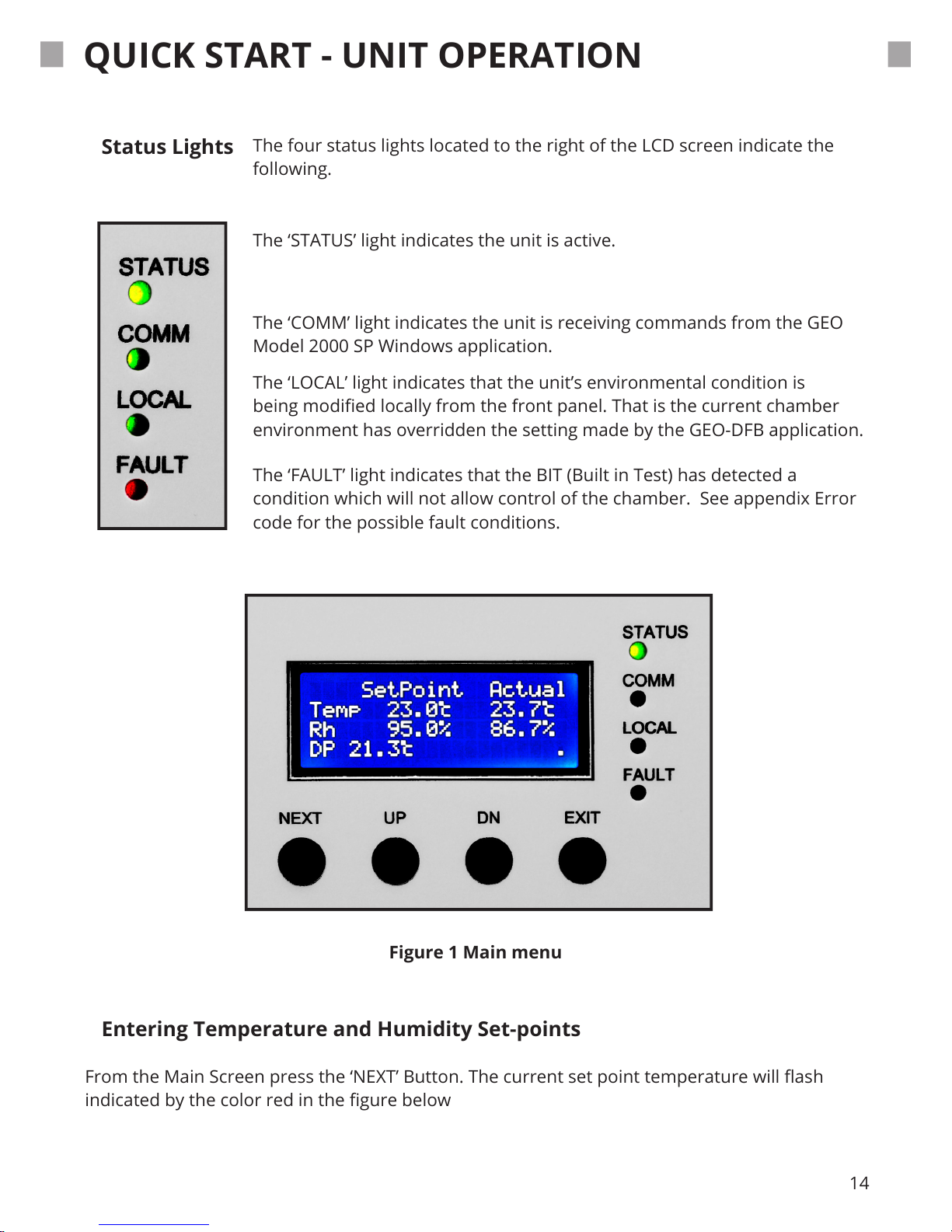
Figure 1 Main menu
Status Lights
The four status lights located to the right of the LCD screen indicate the
following.
Entering Temperature and Humidity Set-points
From the Main Screen press the ‘NEXT’ Button. The current set point temperature will ash
indicated by the color red in the gure below
The ‘STATUS’ light indicates the unit is active.
The ‘COMM’ light indicates the unit is receiving commands from the GEO
Model 2000 SP Windows application.
The ‘LOCAL’ light indicates that the unit’s environmental condition is
being modied locally from the front panel. That is the current chamber
environment has overridden the setting made by the GEO-DFB application.
The ‘FAULT’ light indicates that the BIT (Built in Test) has detected a
condition which will not allow control of the chamber. See appendix Error
code for the possible fault conditions.
QUICK START - UNIT OPERATION
Page 15
15
QUICK START - CHANGING DOOR
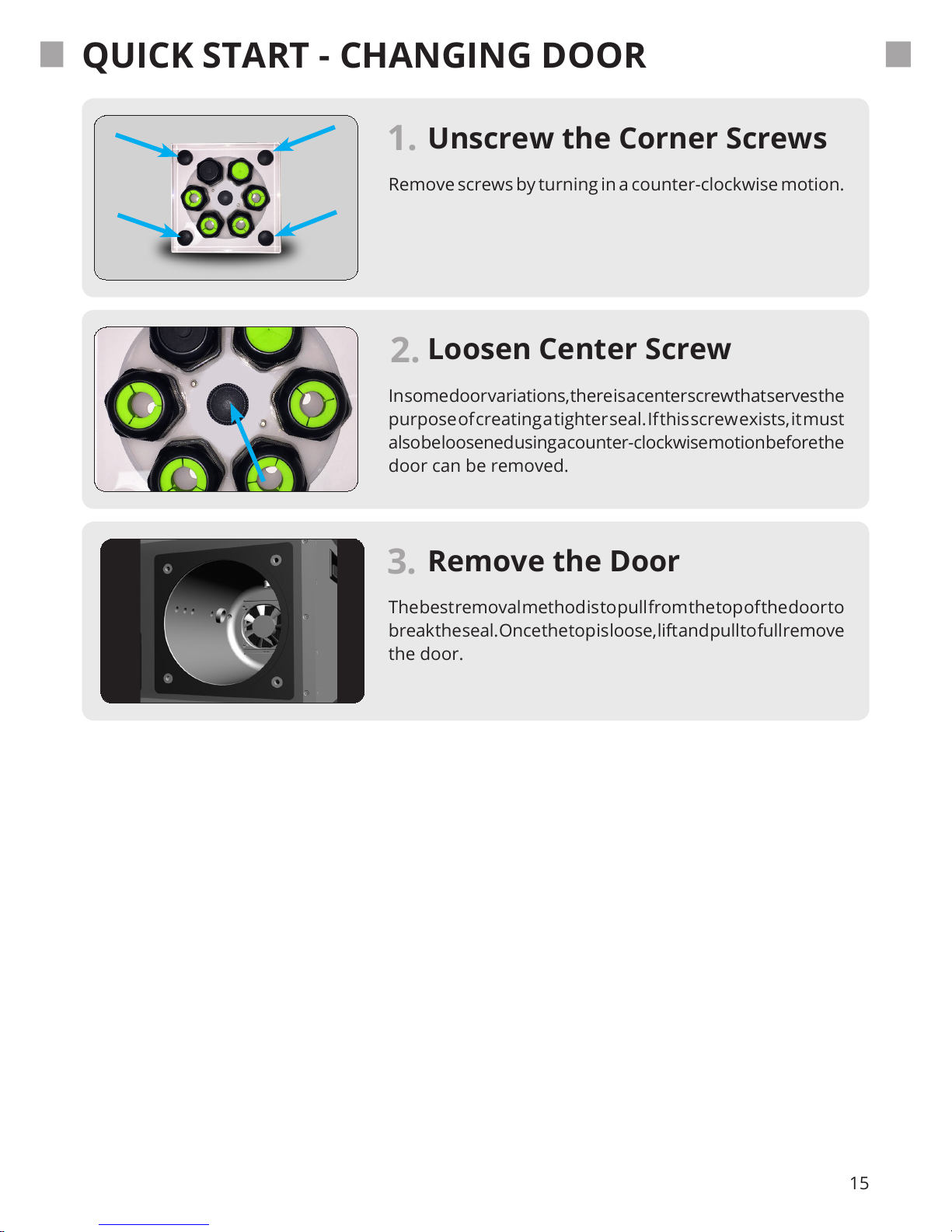
Remove screws by turning in a counter-clockwise motion.
1.
Loosen Center Screw
In some door variations, there is a center screw that serves the
purpose of creating a tighter seal. If this screw exists, it must
also be loosened using a counter-clockwise motion before the
door can be removed.
2.
Remove the Door
The best removal method is to pull from the top of the door to
break the seal. Once the top is loose, lift and pull to full remove
the door.
3.
Unscrew the Corner Screws
Page 16
16
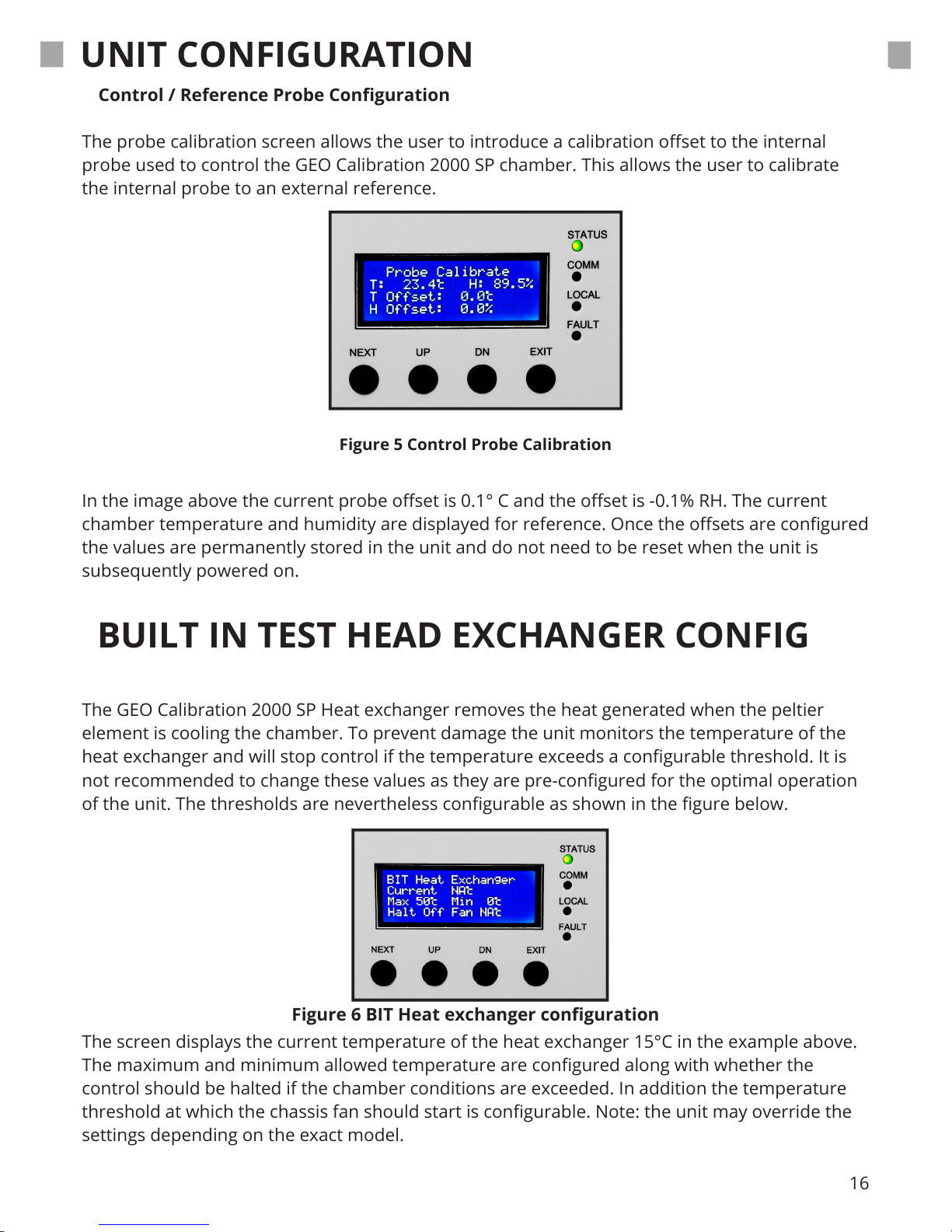
Figure 5 Control Probe Calibration
Figure 6 BIT Heat exchanger conguration
Control / Reference Probe Conguration
The probe calibration screen allows the user to introduce a calibration oset to the internal
probe used to control the GEO Calibration 2000 SP chamber. This allows the user to calibrate
the internal probe to an external reference.
The GEO Calibration 2000 SP Heat exchanger removes the heat generated when the peltier
element is cooling the chamber. To prevent damage the unit monitors the temperature of the
heat exchanger and will stop control if the temperature exceeds a congurable threshold. It is
not recommended to change these values as they are pre-congured for the optimal operation
of the unit. The thresholds are nevertheless congurable as shown in the gure below.
In the image above the current probe oset is 0.1° C and the oset is -0.1% RH. The current
chamber temperature and humidity are displayed for reference. Once the osets are congured
the values are permanently stored in the unit and do not need to be reset when the unit is
subsequently powered on.
UNIT CONFIGURATION
BUILT IN TEST HEAD EXCHANGER CONFIG
The screen displays the current temperature of the heat exchanger 15°C in the example above.
The maximum and minimum allowed temperature are congured along with whether the
control should be halted if the chamber conditions are exceeded. In addition the temperature
threshold at which the chassis fan should start is congurable. Note: the unit may override the
settings depending on the exact model.
Page 17
17
ERROR CODES
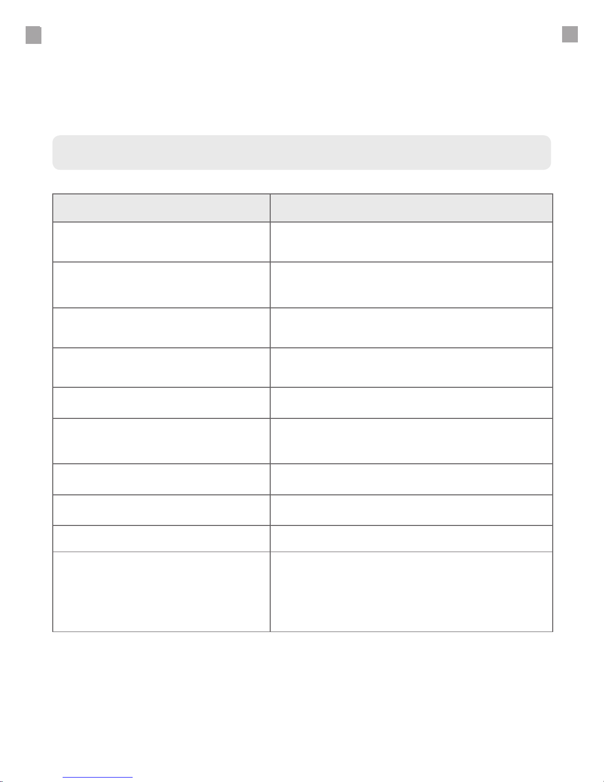
The Model 2000 SP displays error codes through the secondary display.
These are intended to communicate machine status to the user.
Codes and Descriptions
Error Code Description
“No Analog Detected” Internal Hardware Fault Detected
“Internal Probe Fail” Internal Hardware Fault Detected
“No Peltier Temp”
Temperature probe fault. Fans will run
persistently.
“No HumGen Temp” Temperature probe failure.
“HumGen Low Limit”
The temperature of the ambient environment is
too low for unit operation.
“HumGen High Limit”
The humidity generator has exceeded a high
unit. Perform maintenance check of ambient
environment and water supply.
“Peltier High Limit”
The cooling sensor inside the unit is above its
limit.
“EEPROM Cfg Reset”
The unit conguration settings have been reset
to factor default.
“EEPROM Cal Reset” Factory calibration data reset to default.
For questions, please contact GEO Calibration.
Page 18

19
Model 2000 SP | BODY
DIMENSIONS
Metric
Depth
37.00 cm
Width
46.00 cm
Height
23.00 cm
ENCLOSURE Material Powder Coated Aluminum
Model 2000 SP | CHAMBER
DIMENSIONS
Metric
Depth
19.00 cm
Diameter
14.50 cm
ENCLOSURE Material Insulated Plastic
CAPACITY 6 RH Probes 6 - 25 mm
PROBE PORTS 6 Ports
Model 2000 SP | ENTIRE ASSEMBLY
POWER SUPPLY Universal 100 - 260 VAC - 50/60 Hz
WATER Reservoir
Spill Resistant
Water Quality
Est Rell Period
Fill Indicator
150 mL
Yes
Distilled Only
1 Week
Low Warning
Front View
*Typical
*Screen Icon
DESICCANT TYPE Indicating Molecular Sieve
EXTERNAL
INTERFACE
USB Cable and Software Included
WEIGHT Unit Weight METRIC
IMPERIAL
14.00 KG
30.90 LB
SPECIFICATIONS
MECHANICAL AND ELECTRICAL
Page 19
20
CALIBRATION
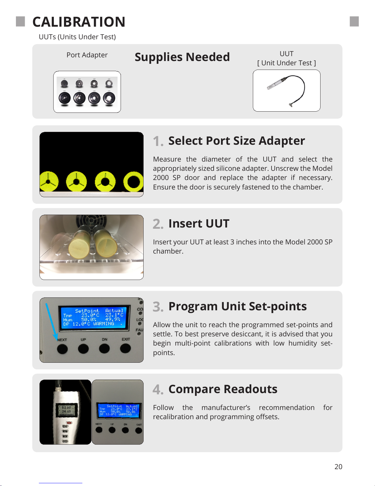
Select Port Size Adapter
Measure the diameter of the UUT and select the
appropriately sized silicone adapter. Unscrew the Model
2000 SP door and replace the adapter if necessary.
Ensure the door is securely fastened to the chamber.
1.
Compare Readouts
Follow the manufacturer’s recommendation for
recalibration and programming osets.
4.
Program Unit Set-points
Allow the unit to reach the programmed set-points and
settle. To best preserve desiccant, it is advised that you
begin multi-point calibrations with low humidity set-
points.
3.
Insert UUT
Insert your UUT at least 3 inches into the Model 2000 SP
chamber.
2.
Supplies Needed
Port Adapter
UUT
[ Unit Under Test ]
UUTs (Units Under Test)
Page 20
21
REFERENCE RECALIBRATION
Overview
The Model 2000 SP functions through the use of a dual PID controller. This controller takes the
humidity and temperature values from an internal capacitance probe and further performs calculations that are then used to generate the user entered humidity and temperature set points.
This sensor is factory calibrated, and upon request, additionally calibrated by an ISO 17025 accredited laboratory using either a chilled mirror or two-pressure primary reference standard.
When calibrating the Model 2000 SP, the chamber must be measured at a variety of temperatures and relative humidity levels. It is recommended that you measurements use a 70 % guard
band to “guard” against any measurement uncertainties. The Model 2000 SP’s humidity and
temperature osets must be changed if the control probe’s readings are found to be outside of
the allowed tolerances when compared to the reference.
Recalibration Intervals
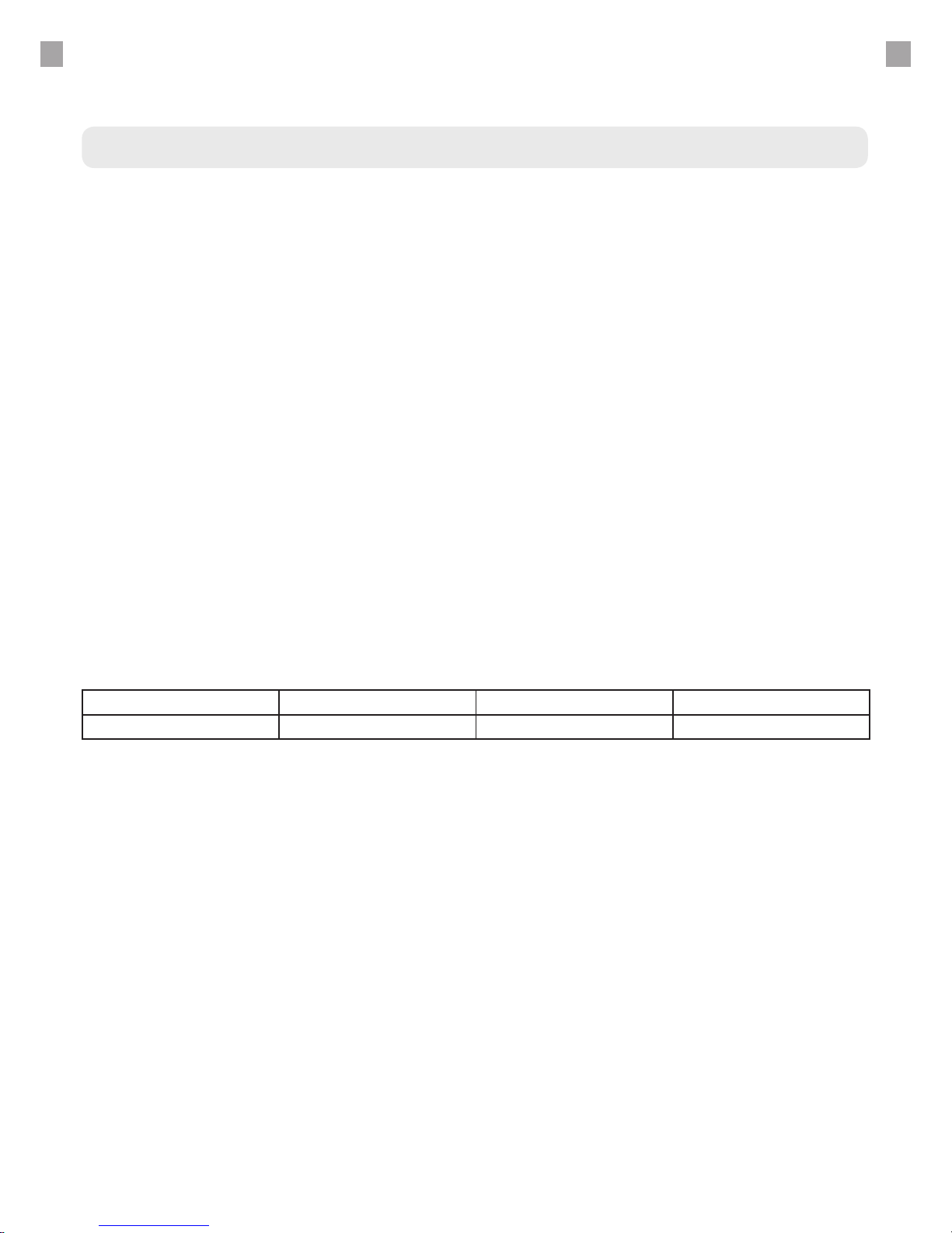
The scope and uncertainty requirements of this calibration will vary per customer. The capacitance probes that we use have an average drift of 1.0% RH per year. You should account for this
interval, as well as your laboratory’s uncertainty budget when calculating out your desired recalibration interval. The table below illustrates accuracy drift after 6, 12 and 24 months.
Timeframe 6 Months 12 Months 24 Months
Dri (%RH) 0.5% RH 1.0% RH 2.0% RH
Based on this information, you may wish to shorten or lengthen your calibration interval to respectively increase accuracy or decrease costs.
Self Re-calibration Overview
We advise that you return your reference probe to GEO Calibration for recalibration. However,
for customers that are international or operate where policy restricts the use of international
services, self recalibration is an option.
The following supplies are needed to recalibrate the internal control/reference probe.
HW4 Calibration Software
HygroClip DI Adapter Cable HC2 Pbe/USB, 6Ft
A calibration reference with uncertainties of 0.5% RH or better.
Control Probe / Reference Sensor
Page 21

22
REFERENCE RECALIBRATION
Self Recalibration Procedure
To read the recalibration procedure of the control / reference probe, please refer to the unit’s
user manual, and the HW4 software manual found at the following URLs:
https://s.campbellsci.com/documents/ca/manuals/hc2-s3-l_man.pdf
https://goo.gl/n7qE1G
Before recalibration of any control probe, ensure that the unit and probe have both completely
settled at 23ºC for at least ten minutes.
Maintaining Probe Accuracy
The following text is the recommended maintanence best practices from Rotronic.
“The HC2S3 probe requires minimal maintenance, but dust, debris, and salts on the lter cap will
degrade sensor performance. Check the white lter on the end of the sensor for debris. If dirt or
salt is engrained into the lter, it should be cleaned with distilled water or replaced. Make sure
the lter is connected rmly with your ngers — do not over tighten.
Check the radiation shield monthly to make sure it is free from dust and debris. To clean the
shield, remove the sensor from the shield. Dismount the shield. Brush all loose dirt o. If more
eort is needed, use warm, soapy water and a soft cloth or brush to thoroughly clean the shield.
Allow the shield to dry before remounting.
Replace corroded, discoloured or clogged lters. To replace the lter, unscrew the lter from the
probe and pull it straight away, being careful not to bend or damage the sensors. Before putting
on the replacement lter, check the alignment of the sensors with the probe, and if necessary,
carefully correct the alignment before installing the lter.
The Teon lter is recommended when the sensor is installed in close proximity to the ocean or
other bodies of salt water. A coating of salt (mostly NaCl) may build up on the radiation shield,
sensor, lter and even the sensors. A build-up of salt on the lter or sensors will delay or destroy
the response to atmospheric humidity.
Long term exposure of the relative humidity sensor to certain chemicals and gases may affect the characteristics of the sensor and shorten its life. The resistance of the sensor depends
strongly on the temperature and humidity conditions and the length of the pollutant inuence.”
Page 22
23
ENTERING MODEL 2000 SP OFFSETS
Supplies Needed
Windows PC with
USB Port
USB Cable
Unit Oset Calibration via Hyper-terminal
Accessing the Device Manager
The Model 2000 SP also allows users to make two, single point adjustments for both tempera-
ture and humidity. It is recommended that users recalibrate their unit as needed to t their
overall uncertainty requirements.
The reference sensor used for this recalibration should be either a two-pressure or chilled
mirror primary measurement standard.
The following software items are required for this recalibration:
- Windows Device Manager
- PuTTY *
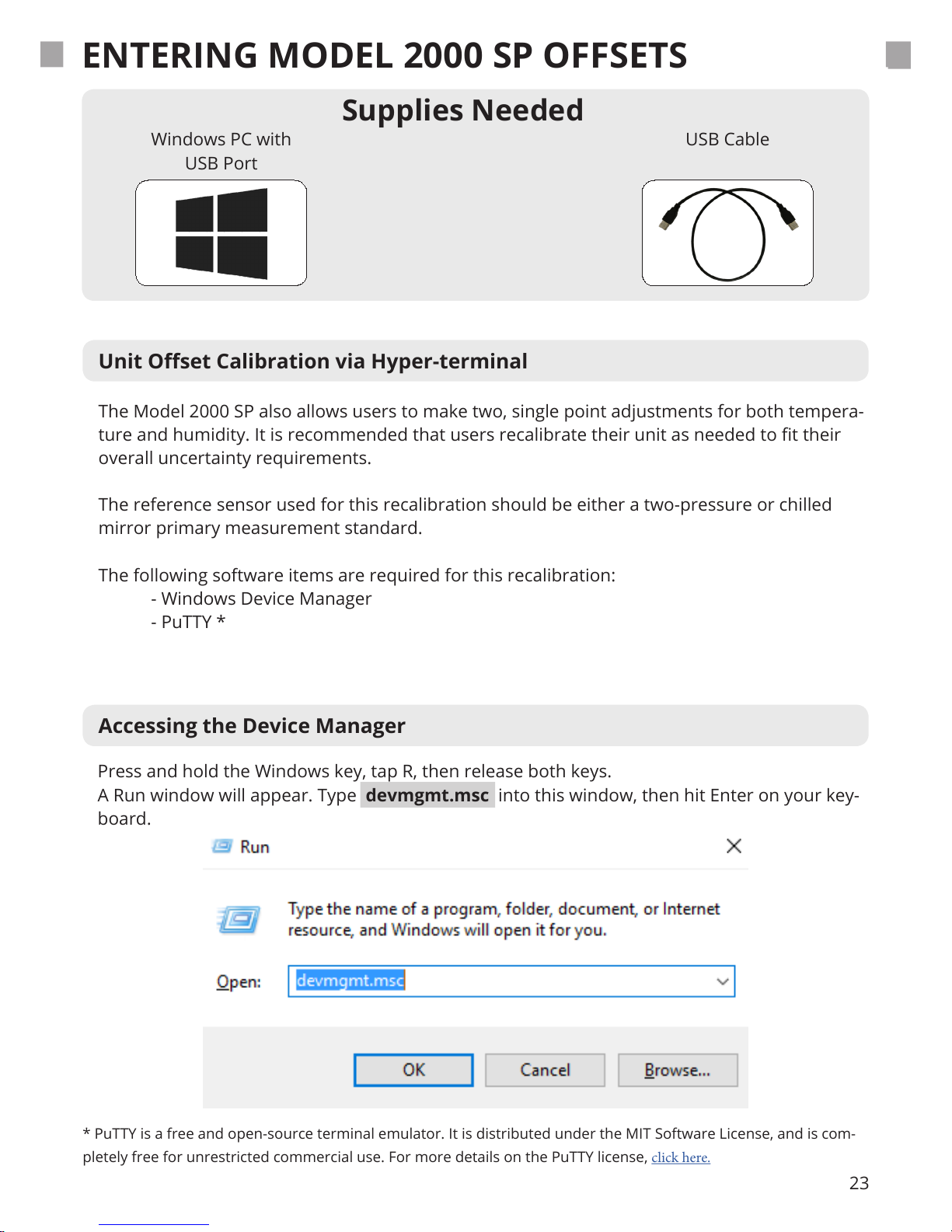
Press and hold the Windows key, tap R, then release both keys.
A Run window will appear. Type devmgmt.msc into this window, then hit Enter on your key-
board.
* PuTTY is a free and open-source terminal emulator. It is distributed under the MIT Software License, and is com-
pletely free for unrestricted commercial use. For more details on the PuTTY license, click here.
Page 23
24
ENTERING MODEL 2000 SP OFFSETS
PuTTY Setup
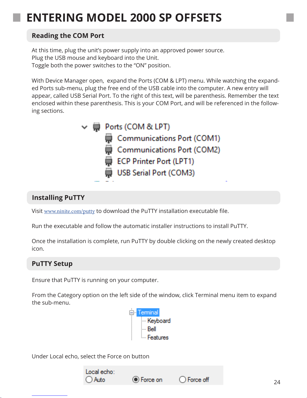
Ensure that PuTTY is running on your computer.
From the Category option on the left side of the window, click Terminal menu item to expand
the sub-menu.
Installing PuTTY
Reading the COM Port
At this time, plug the unit’s power supply into an approved power source.
Plug the USB mouse and keyboard into the Unit.
Toggle both the power switches to the “ON” position.
With Device Manager open, expand the Ports (COM & LPT) menu. While watching the expand-
ed Ports sub-menu, plug the free end of the USB cable into the computer. A new entry will
appear, called USB Serial Port. To the right of this text, will be parenthesis. Remember the text
enclosed within these parenthesis. This is your COM Port, and will be referenced in the follow-
ing sections.
Visit www.ninite.com/putty to download the PuTTY installation executable le.
Run the executable and follow the automatic installer instructions to install PuTTY.
Once the installation is complete, run PuTTY by double clicking on the newly created desktop
icon.
Under Local echo, select the Force on button
Page 24
25
Reading Temperature and Humidity Osets
Connecting Through PuTTY
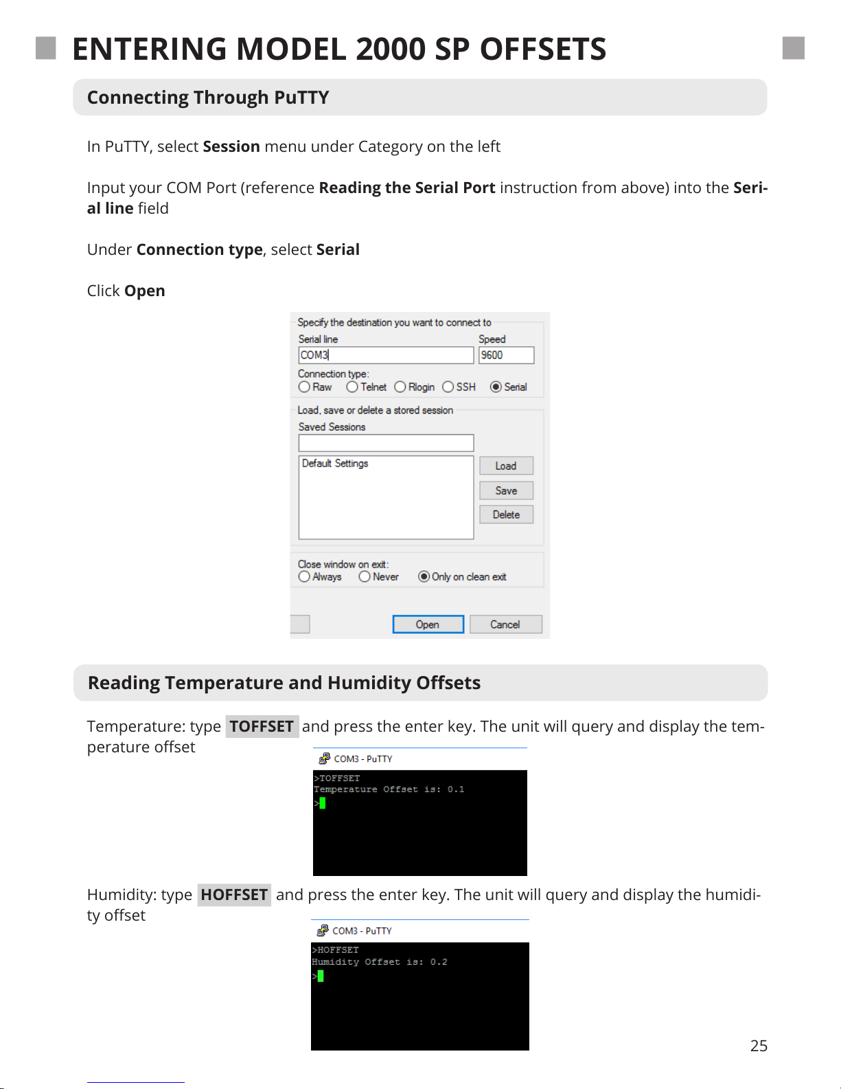
Temperature: type TOFFSET and press the enter key. The unit will query and display the tem-
perature oset
Humidity: type HOFFSET and press the enter key. The unit will query and display the humidi-
ty oset
In PuTTY, select Session menu under Category on the left
Input your COM Port (reference Reading the Serial Port instruction from above) into the Seri-
al line eld
Under Connection type, select Serial
Click Open
ENTERING MODEL 2000 SP OFFSETS
Page 25
26
Changing Humidity and Temperature Osets
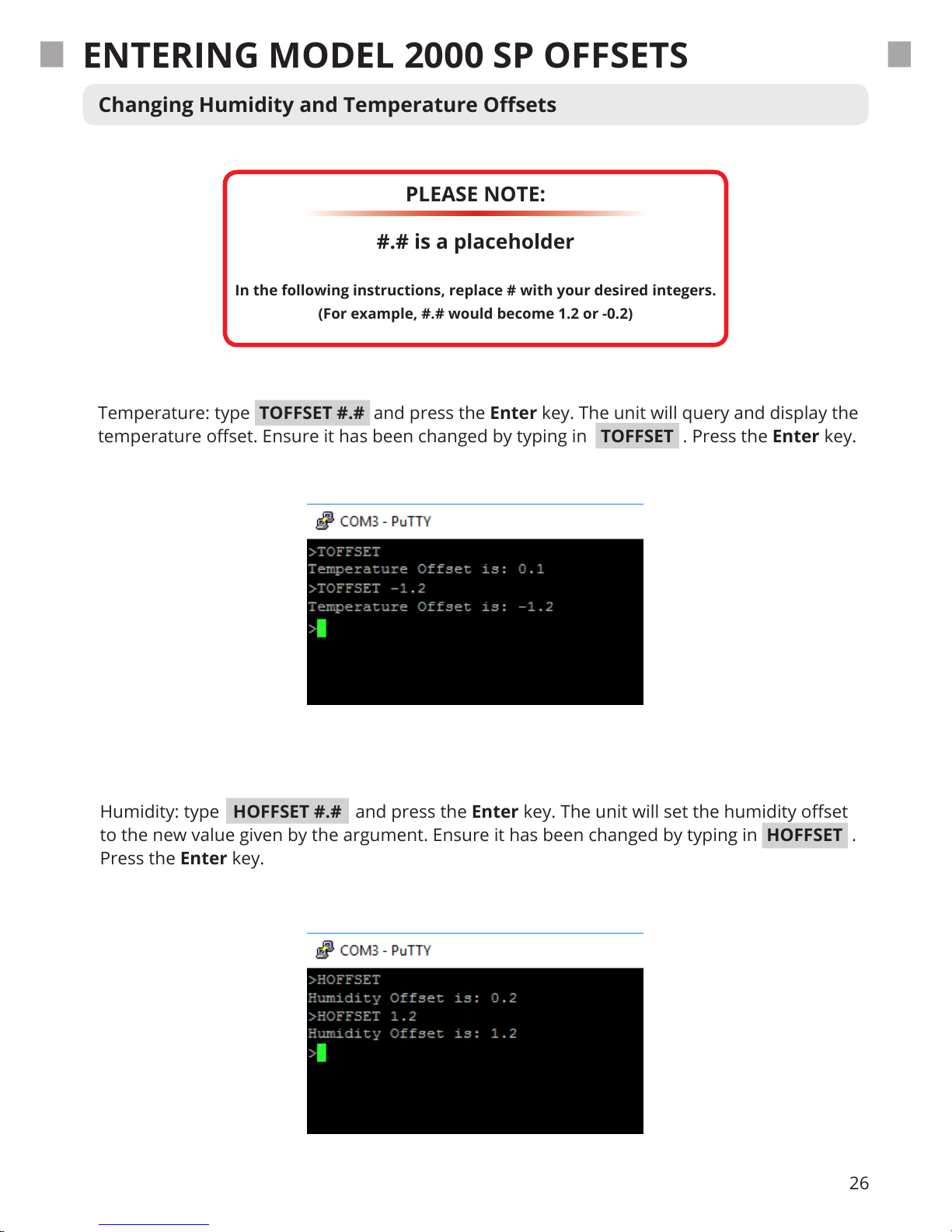
Temperature: type TOFFSET #.# and press the Enter key. The unit will query and display the
temperature oset. Ensure it has been changed by typing in TOFFSET . Press the Enter key.
Humidity: type HOFFSET #.# and press the Enter key. The unit will set the humidity oset
to the new value given by the argument. Ensure it has been changed by typing in HOFFSET .
Press the Enter key.
PLEASE NOTE:
#.# is a placeholder
In the following instructions, replace # with your desired integers.
(For example, #.# would become 1.2 or -0.2)
ENTERING MODEL 2000 SP OFFSETS
Page 26

27
SAFETY WARNING
General Safety Information
● Read all provided and available safety information before you use the Model 2000 SP.
● Carefully read all available instructions.
● Use only the power cord and supply approved for the voltage for the Model 2000 SP.
● Replace the power cord if the insulation is damaged or if the insulation shows any signs of
wear.
● Make sure the ground conductor in the power cord is connected to a functioning ground.
Disruption of the ground could put voltage on the chassis that could cause death.
● Use the Model 2000 SP only as specied, or the protection supplied by the Product can be
compromised.
● Do not put the Model 2000 SP where access to the power cord isn’t possible.
● Immediately cease using and disable the Model 2000 SP if it is damaged.
● Do not use the Model 2000 SP if it operates in an incorrect way.
● Do not operate the Model 2000 SP with unit casing removed. Hazardous voltage exposure is
possible.
● Use only specied GEO Calibration replacement parts.
● The Model 2000 SP may only be repaired by approved technicians.
● The Model 2000 SP reservoir must be completely emptied before shipment.
● Do not use the Model 2000 SP around explosive gas, vapor, or in damp or wet environments.
Page 27

28
SAFETY WARNING
Disposal Safety Information
European Union—Disposal Information
The symbol above means that according to local laws and regulations your product and/or its
desiccant shall be disposed of separately from household waste. When this product reaches its
end of life, take it to a collection point designated by local authorities. The separate collection
and recycling of your product and/or its desiccant at the time of disposal will help conserve
natural resources and ensure that it is recycled in a manner that protects human health and the
environment.
Page 28
29
TECHNICAL SUPPORT
GEO Calibration Inc.
Locations
2190 Smithtown Avenue
Ronkonkoma, NY
USA
Tel.: +00/(1) 631 / 471 - 6157
Fax: +00/(1) 631 / 471 - 6158
[email protected]
www.geocalibration.com
GEO Calibration Inc
2190 Smithtown Avenue, Ronkonkoma, NY 11779, USA
Tel.: +001 (631) 471 - 6157 ● Fax: +001 (631) 471 - 6158
© GEO Calibration Inc. 2017
Page 29

30
Unit Repair Procedure
● Contact GEO Calibration and request an RMA #.
● Have the Product information ready such as the purchase date and serial
number to schedule the repair.
● Ship the unit to GEO in the original shipping container or one designed
specically for “Safe Travel”.
● Apply your RMA # on the outside of the shipping package in large
numbers.
● Apply the top right portion of your quotation with RMA # and bar-code to
the outside of the shipping package, so that it is visible.
● Include a copy of this email quote inside your package.
● Estimated Return Ship-Date is 15 business days from the date both the
unit and a valid method of payment is received.
● On the Purchase Order, please ensure the “Vendor Name” is GEO
Calibration Inc., and the address is 2190 Smithtown Avenue, Ronkonkoma
NY 11779.
● Payment Terms are “Immediate Payment” from Date of Invoice,
FOB Origin, the respective Dollar Amounts, and any return shipping
instructions are completed. (Please, do not send a copy of your internal
“Purchase Requisition” as we need the actual “Purchase Order” with the
above items included).
● Reference the RMA # on the completed PO and forward a copy via fax
(631.471.6158) or email to: [email protected]
● If credit card is being used for payment and has not been provided as yet,
please call +1 (631) 471 - 6157 and provide information; referencing your
RMA # when you call.
● ** Exception pricing may apply upon evaluation by the lab. If applicable,
this will be presented in a formal re-quote before proceeding.
● Please note that a “Payment Method” must be on le, reviewed and
approved before any service work may begin on your item. If you have
● If you have any questions do not hesitate to call or email us.
REPAIRS
Please ship the unit to:
Attn: Repairs
GEO Calibration Inc.
2190 Smithtown Avenue
Ronkonkoma, NY, 11779
The United States of America
Page 30
31
UNIT MAINTENANCE
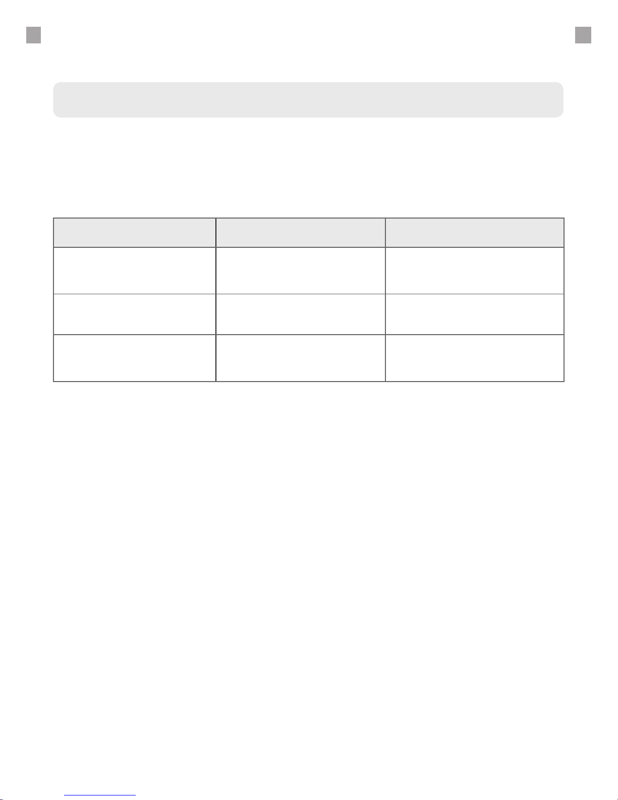
Maintenance Schedule
● GEO Recommendation
GEO Calibration recommends that the unit be annually shipped back to our facility for
general maintenance.
Daily Semi-Annual As Needed
General Cleaning
(Use Proper Cleaning
Materials)
Control Probe Calibration
Rell Reservoir with Distilled
Water
Ensure the Water
Reservoir is Filled
Replace Desiccant Canister
Ensure the Desiccant
Ports contain at least
one fresh canister.
Page 31

32
MAINTENANCE GUIDE
Overview
The Model 2000 SP ships with a fresh desiccant canister. Each time the Model 2000 SP dries the
internal volume of air, the desiccant will become more saturated with water. For optimal performance, the user must periodically replenish or replace the used desiccant. The desiccant type is
molecular sieve, which may be regenerated by the user through heating.
The user must replace the desiccant as soon as they see drying performance begin to degrade.
To aid in this process, the Model 2000 SP has an on-screen indicator that displays once sub par
drying performance is detected. In addition to the on-screen indicator, the desiccant itself also
contains a chemical that changes color from blue to pink when saturated with water. The user
should change the desiccant once approximately 75% of the molecular sieve has changed in
color from blue to pink.
Desiccant Change Procedure
We advise that you purchase extra replacement desiccant canisters directly from GEO Calibration. It is possible to purchase the desiccant in bulk, disassemble the canister and replace the
used desiccant with unused desiccant, however, this procedure requires the user to carefully
re-assemble the desiccant canister. If this re-assembly is done incorrectly, then air leaks may
occur and the unit performance may suer.
For visual instructions on how to perform a rell of a desiccant canister, please see the next
page.
Additional instructions can also be found on the website of the desiccant supplier.
https://secure.drierite.com/catalog3/page19b.cfm
Desiccant
Page 32
33
MAINTENANCE GUIDE - DESICCANT CHANGE
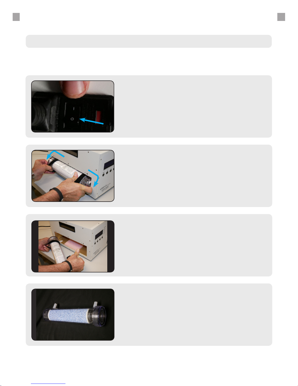
Firmly Grasp Desiccant
This will cause the old desiccant canister to slide from
the female adapters. Remove this desiccant completely
from the housing and set aside.
3.
Loosen Hook & Loop Straps
2.
Instructions
Changing the Desiccant
Power O the Unit
Ensure that the unit is powered o before proceeding
with a desiccant change.
1.
Locate New Desiccant Canister
Remove the used desiccant canister and replace with
the fresh desiccant canister.
4.
Page 33
34
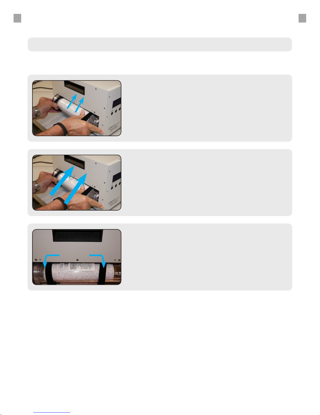
MAINTENANCE GUIDE - DESICCANT CHANGE
Secure Hook & Loop Straps
7.
Firmly Insert Desiccant Canister
Ensure the hose barbs properly line up with the sockets
on the inside of the desiccant housing.
5.
Press with Force to Ensure
Firmly press the seal with both thumbs into the canister
housing.
6.
Changing the Desiccant - Continued
Page 34
35
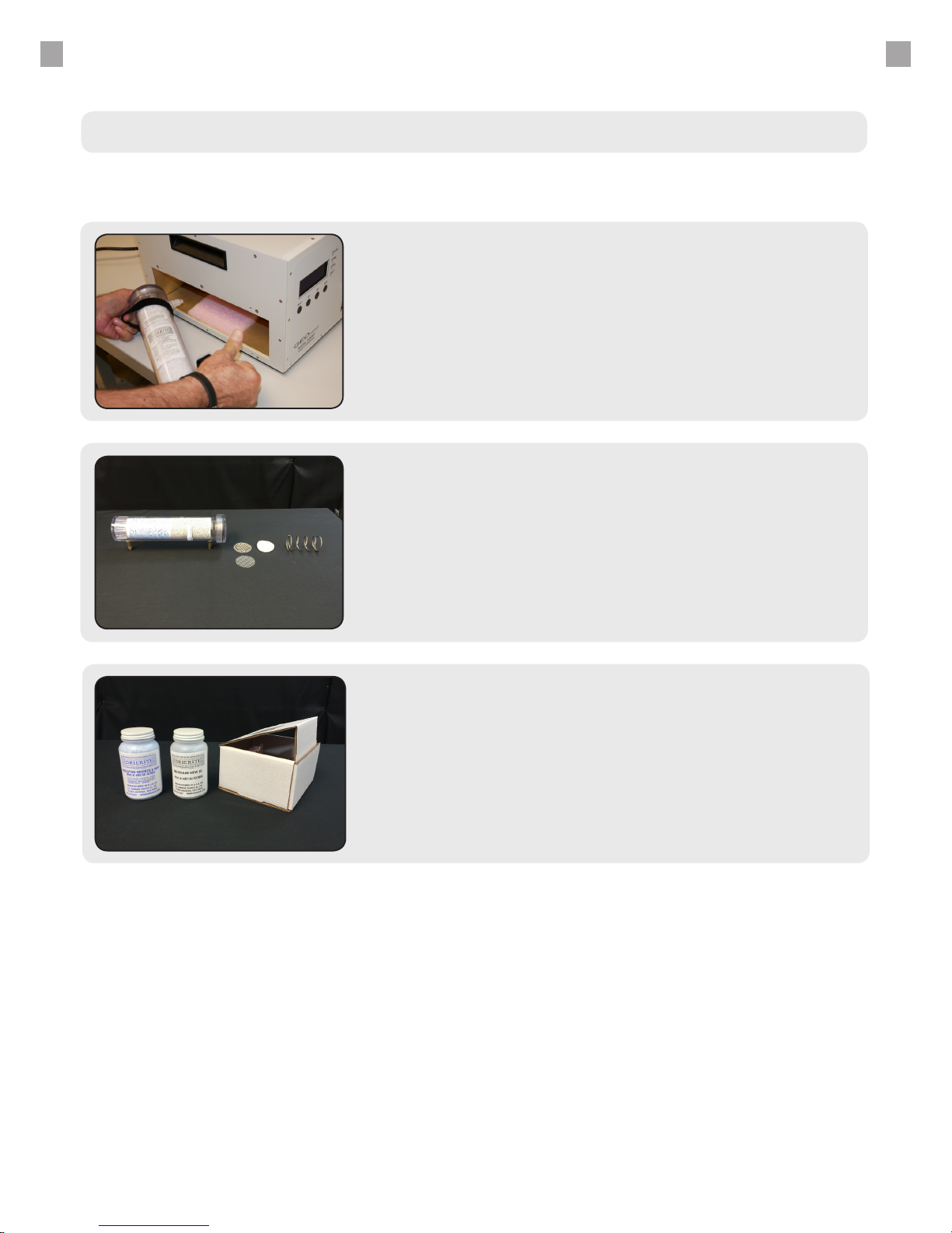
MAINTENANCE GUIDE - DESICCANT REFILL
Desiccant Rell Instructions
Open Top Cover of Desiccant
Save the spring, the sieve and the three white felt lters.
Discard previous desiccant. Wipe the inside of the desiccant
cannister with a clean cloth. Beat lters clean of debris.
Clean the sieve and the spring.
2.
Fill Canister with Desiccant
Put the white lter at the bottom. Put the white desiccant
inside. Gently tap. Put another lter. Add blue desiccant.
Put one more lter. Put one more sieve. Put the spring.
Tighten the cover.
3.
Remove Desiccant
Follow the initial steps from the previous section entitled
“Desiccant Change”.
1.
Page 35
36
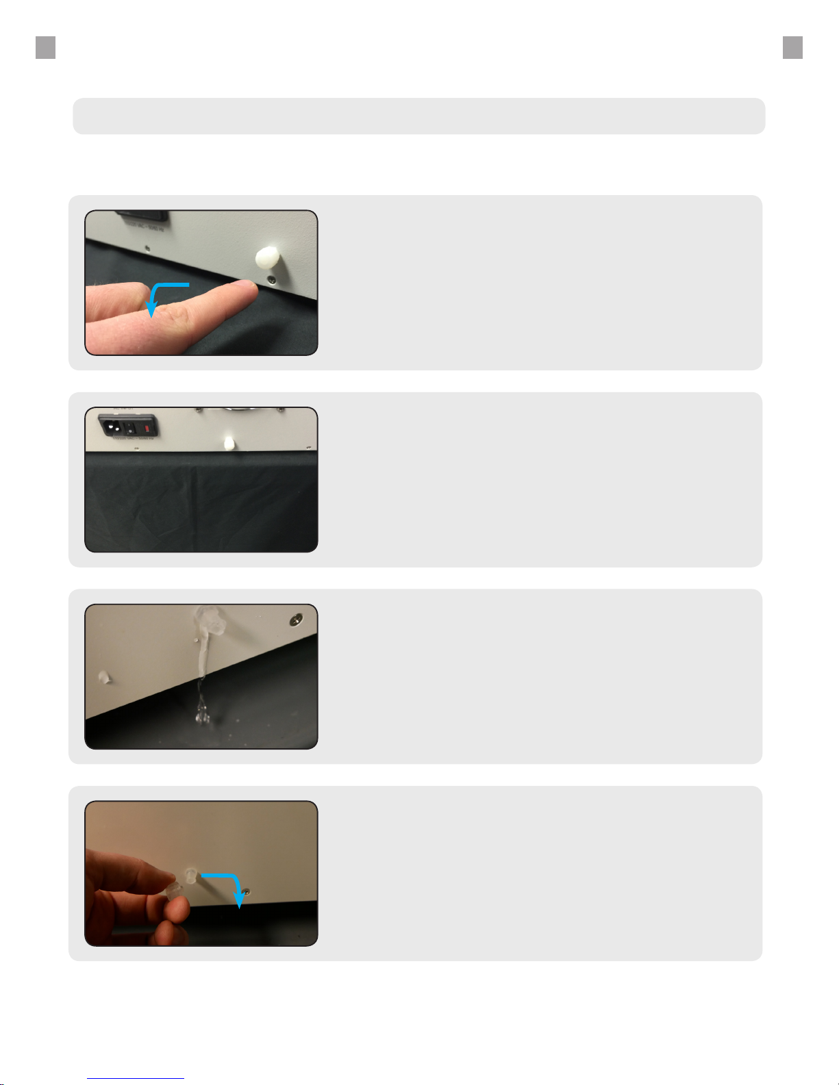
Draining the Unit
Move the Unit to Table Edge
Position a bowl shaped object underneath the unit to
catch the drained water.
2.
Replace & Tighten Drain Cap
Tighten the drain cap in a clockwise motion. Ensure that
the drain cap has a tight seal and no water is leaking.
4.
Remove the Drain Cap
Tilt the unit to ensure maximum water removal.
3.
Locate the Main Drain Port
Turn the cap counter-clockwise to remove.
1.
MAINTENANCE GUIDE - DRAINING THE UNIT
Page 36
37
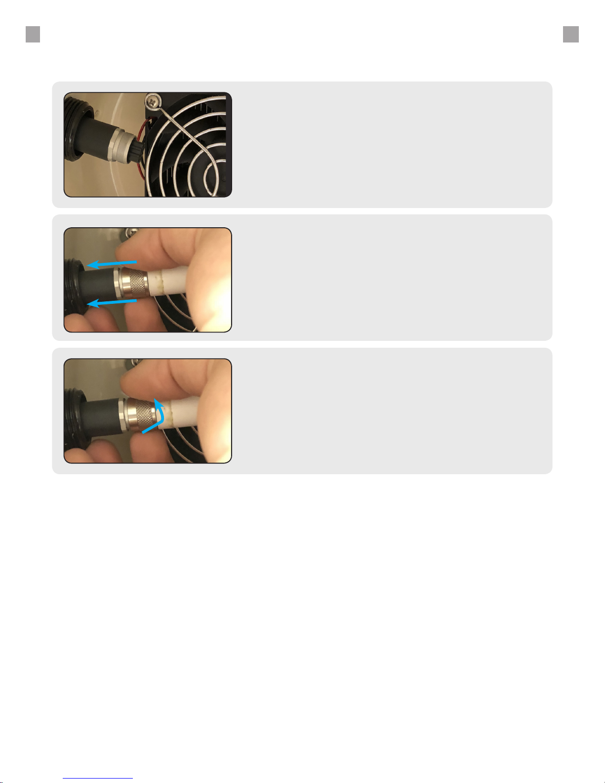
Press Probe into Connector
Slowly rotate the probe head as you press into the
cabling body. You will feel the probe “seat” itself once
the male - female parts align.
2.
Secure Metal Connector
Twist the metal connector away from the chamber
entrance to secure the probe head to the probe cabling
body.
3.
Locate Probe Connector
1.
MAINTENANCE GUIDE - PROBE REPLACEMENT
Page 37
38
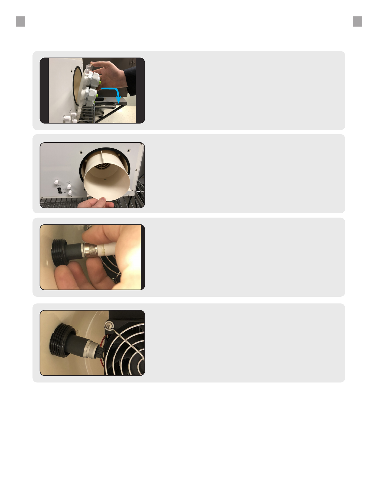
Remove Chamber Insert
2.
Loosen Metal Connector
Remove Probe Head
Twist towards the chamber opening to loosen.
3.
4.
Open Chamber Door
Turn the screws counter-clockwise to loosen.
Remove the door.
1.
MAINTENANCE GUIDE - PROBE REMOVAL
Page 38
39
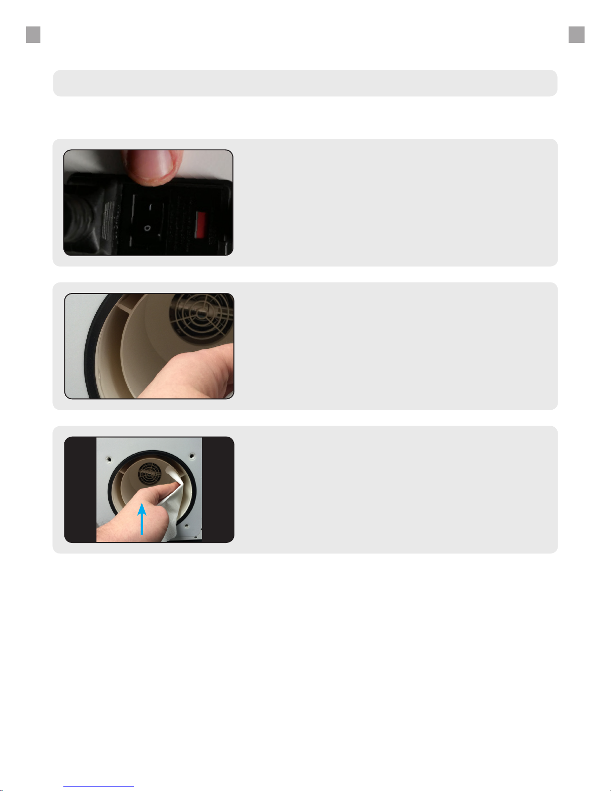
Open the Chamber Door
Follow the door opening procedure from the quick start
guide.
2.
Remove Condensation
Clean all condensation with an absorbent cloth such as a paper
towel or bath towel.
3.
MAINTENANCE GUIDE - CONDENSATION
Condensation in the Chamber
Power O the Unit
Ensure that the unit is powered o. This is so that no
desiccant is wasted while the unit is not in operation.
1.
Page 39

40
© 2017 GEO Calibration Inc. All rights reserved.
INDUSTRIES
TARGE T
PHARMACEUTICAL
MANUFACTURING
CALIBRATION LABS
BIOMEDICAL
R&D
FACIL ITIES
AGRICULTURAL
AUTOMOTIVE
MANUFACTURING
AEROSPACE
HOSPITAL / MEDICAL
CLEAN ROOMS
Sales@GeoCalibration.com
www.GeoCalibration.com
(631) 471 - 6157
2190 Smithtown Ave,
Ronkonkoma NY 11779
USA
CONTACT US:
GEO
Headquarters
Proudly Made
in the USA
 Loading...