

Page 1
1
OWNER’S MANUAL
FEATURES:
• Ultra Lightweight 27lb Compact Design • Innovative Acoustic Array™ Speaker System
• 10” Woofer w/4 x 2.5” Cone-driver Line Array • Slanted Cabinet Design for Improved Projection
• XLR Mic and ¼” Instrument Inputs • Two Identical Preamp Channels w/Active EQ & Sweepable Mids
• Phantom Power for Condenser Mics • Unique Contour Circuit for Quick Tonal Adjustments
• Signal Phase Reverse Switch • Adjustable Digital Reverb and Chorus on each Channel
• Bottom Speaker Stand Mount
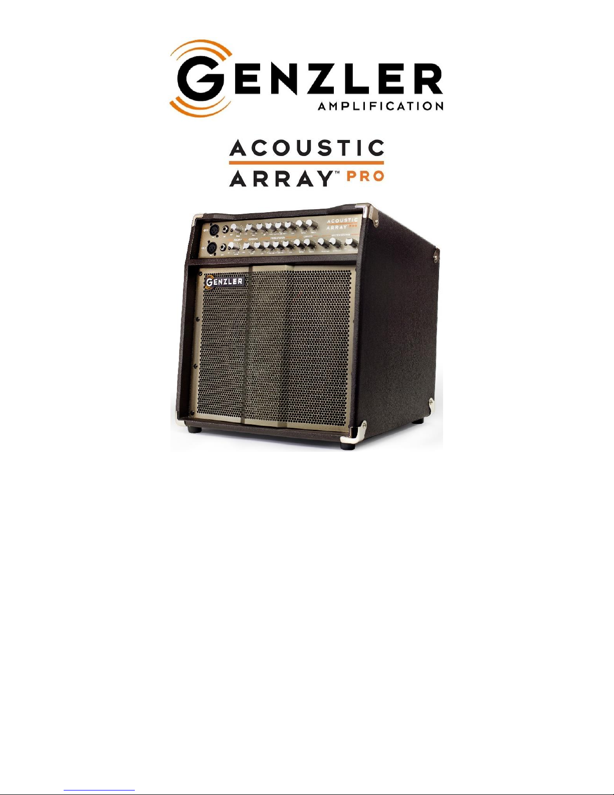
PRODUCT DESCRIPTION
– The
ACOUSTIC ARRAY™ PRO
represents the next generation in professional acoustic
instrument amplification. The innovative speaker system features a 10” woofer and integrated 4 x 2.5” cone-driver line
array element which delivers smoothness, clarity, dynamics and dispersion like no other acoustic amplifier available. This
array system design reproduces the natural tone of the acoustic stringed instrument and greatly increases the horizontal
dispersion and projection, providing even response across the performance area. The electronics feature our dual
channel preamp design, light-weight Class D power section, and a full featured rear panel interface. All together the
ACOUSTIC ARRAY™ PRO
offers the most pure and natural reproduction of the acoustic instrument along with ease and
versatility in set up and performance.
Page 2
2
FRONT PANEL
T
he
ACOUSTIC ARRAY™ PRO
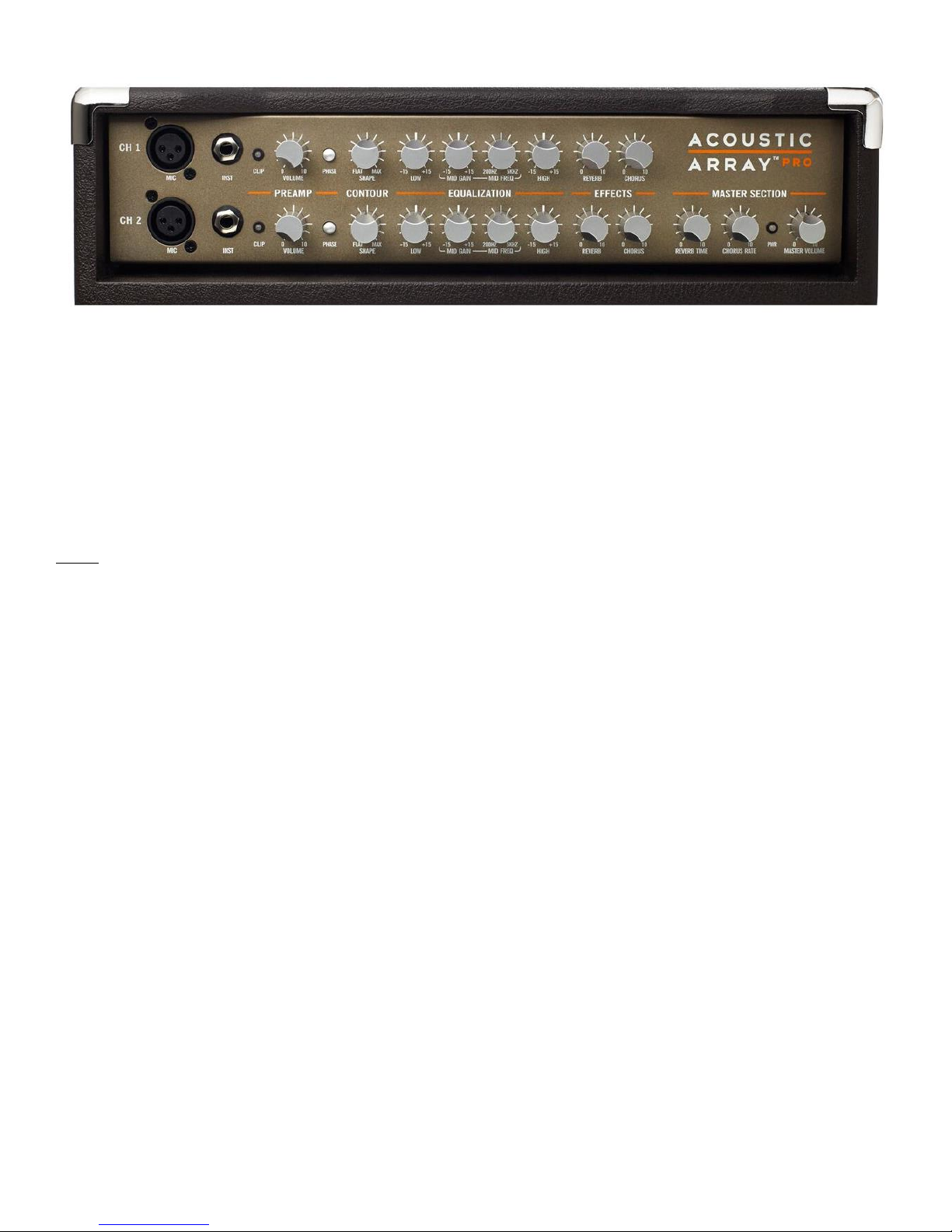
offers a full featured preamp design with 2 identical channels.
MIC INPUT
– This jack is a balanced XLR microphone level input which contains an “RFI” filter (radio frequency
interference) to eliminate unwanted noise. It also provides IEC P12(L) phantom power (12 volt) which works well with
most microphones found in the live sound industry. If a microphone requiring a higher voltage is to be used then an
appropriate external phantom power supply can be added in line.
NOTE – To prevent audible pops and unwanted noises, it is recommended that you turn down the PREAMP VOLUME on
the appropriate channel anytime you are connecting to or disconnecting from the MIC inputs.
INST INPUT
– This jack is a standard ¼” unbalanced instrument input. The INST input stage contains an FET input
buffer circuit with an input impedance of 5 Meg ohms, a 40 Hz active high pass filter, and an “RFI” filter to eliminate
unwanted noise.
COMBINING MIC AND INST INPUTS
– A unique feature of the
ACOUSTIC ARRAY™ PRO
is the ability to mix the MIC
(XLR balanced) and INST (¼” unbalanced) inputs. This effectively allows the amplifier to function as a 4 channel
amplifier. The most effective way to use this feature is to first set the PREAMP VOLUME, CONTOUR, and
EQUALIZATION on the desired channel using the MIC input and then adjust the level and tone controls on the instrument
itself (assuming that it has them) to blend the levels and tone between the MIC and INST inputs. The amp’s channel
EQUALIZATION and CONTOUR will be common to both the MIC and INST inputs for that channel.
CLIP LED
– This LED shows the operating status of the preamp channels and EQUALIZATION stages. When this LED
flashes, clipping of the preamp channels or EQUALIZATION stages is occurring or about to occur. Adjusting the
PREAMP VOLUME or the relevant EQUALIZATION controls down will remove the clip condition. Adjust the final overall
volume with the amp’s MASTER VOLUME.
PREAMP VOLUME
– This control sets the preamp’s input volume level for both the MIC and INST inputs.
PHASE SWITCH
– This switch reverses the phase of the instrument’s signal. By reversing the phase, feedback can be
reduced if caused by sympathetic vibrations between the speaker system and the instrument. Under some conditions,
changing the phase can drastically improve the acoustic output from the amplifier and can improve the playability of the
instrument.
Page 3
3
CONTOUR –
Our unique CONTOUR circuit offers a continuously variable pre-shaped curve that boosts lows and highs
while simultaneously cutting mid frequencies. The slope is fairly gentle which keeps the tone shaping very musical. This
curve covers a wide frequency range and can be used by itself or in conjunction with the EQUALIZATION controls. When
the SHAPE control is all the way off (CCW) the CONTOUR response curve is completely FLAT.
EQUALIZATION
– The
ACOUSTIC ARRAY™ PRO
contains an active 3 band equalizer with a sweepable parametric
mid-range frequency control. The mid-range filter is typically (but not always) used to reduce or remove offending
frequencies in the instrument or room response; or to boost response to achieve a particular voicing. Spend some time
experimenting so that the process becomes creative as well as corrective.
LOW: +/- 15dB boost/cut shelving curve with a corner frequency of 75Hz
MID GAIN: +/- 15dB boost/cut of the variable mid frequency selected
MID FREQ.: Variable mid frequency from 200Hz-5kHz
HIGH: +/- 15dB boost/cut shelving curve with a corner frequency of 7.5kHz
EFFECTS –
Each channel has its own set of REVERB and CHORUS level controls that provide the user with the most
flexibility in having either or both effects on either channel.
REVERB:
This control sets the level for the amount of Reverb effect.
CHORUS:
This control sets the level for the amount of Chorus effect.
MASTER SECTION –
REVERB TIME:
This control adjusts the decay time of the internal digital reverb effect. The more the control is
turned clockwise the longer the decay time. This provides a wide range of useable reverb effects. A good
starting point for this control would be a setting around 11 o’clock to 1 o’clock. Turning this control to 0 turns off
this effect entirely. The volume of this effect is controlled by the Channel REVERB control.
CHORUS RATE:
This control adjusts the rate and depth of the digital chorus effect. The more the control is
turned clockwise, the faster the chorus rate and the shallower the depth of the effect. A good starting point for
this control would be a setting around 10 o’clock to noon. Turning this control to 0 turns off this effect entirely.
The volume of this effect is controlled by the Channel CHORUS control.
MASTER VOLUME
: This control adjusts the overall volume of the amplifier and also adjusts the input level of the
EFFECTS LOOP RECEIVE and AUX INPUT jacks. Typically, best results are obtained when this control is
operated between the 9 o’clock and 3 o’clock positions.
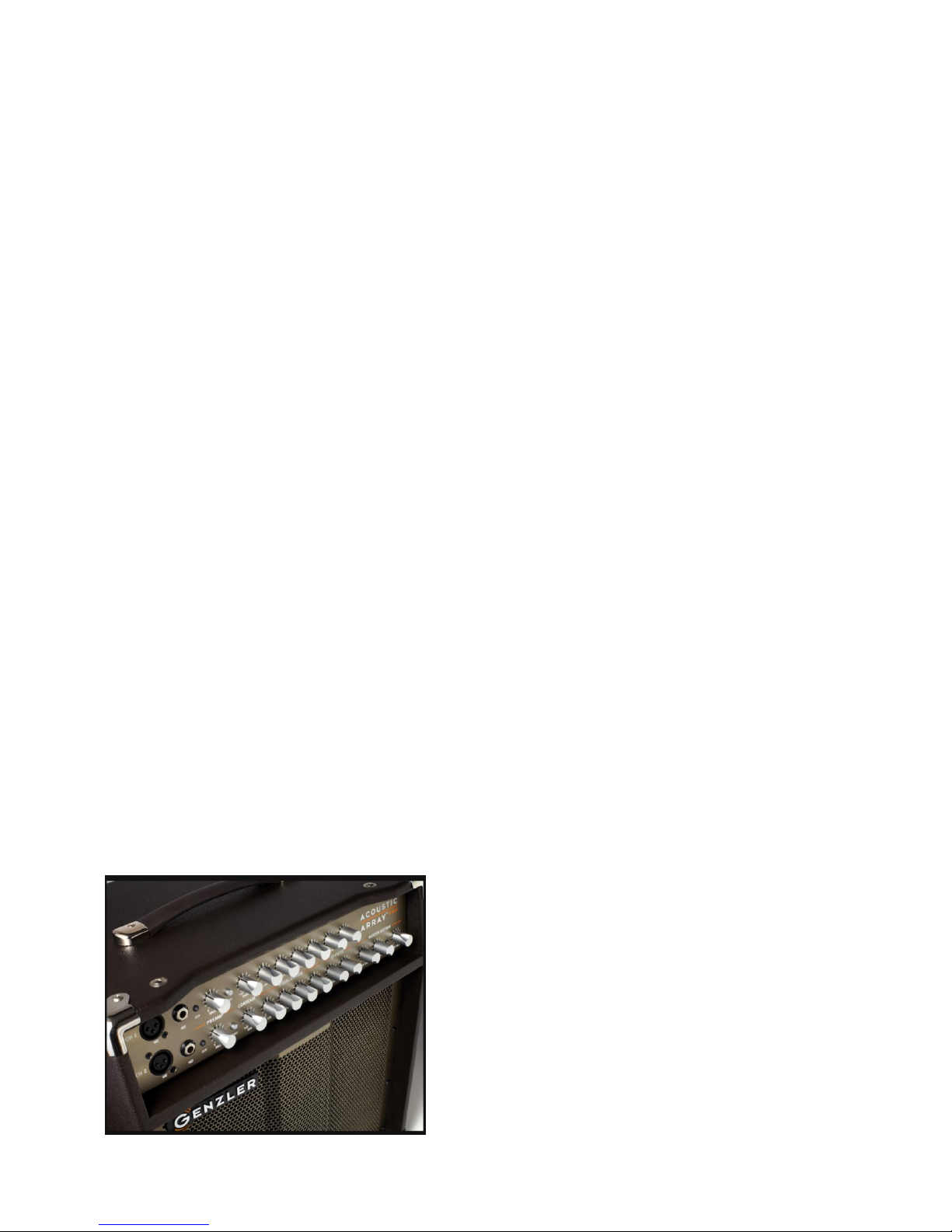
CUSTOM CONTROL KNOBS
– We’ve included custom
designed control knobs which offer marker lines for precision
adjustments and a “finger positioning dip” so that the player can
know the knob position by tactile feel alone.
Page 4
4
REAR PANEL
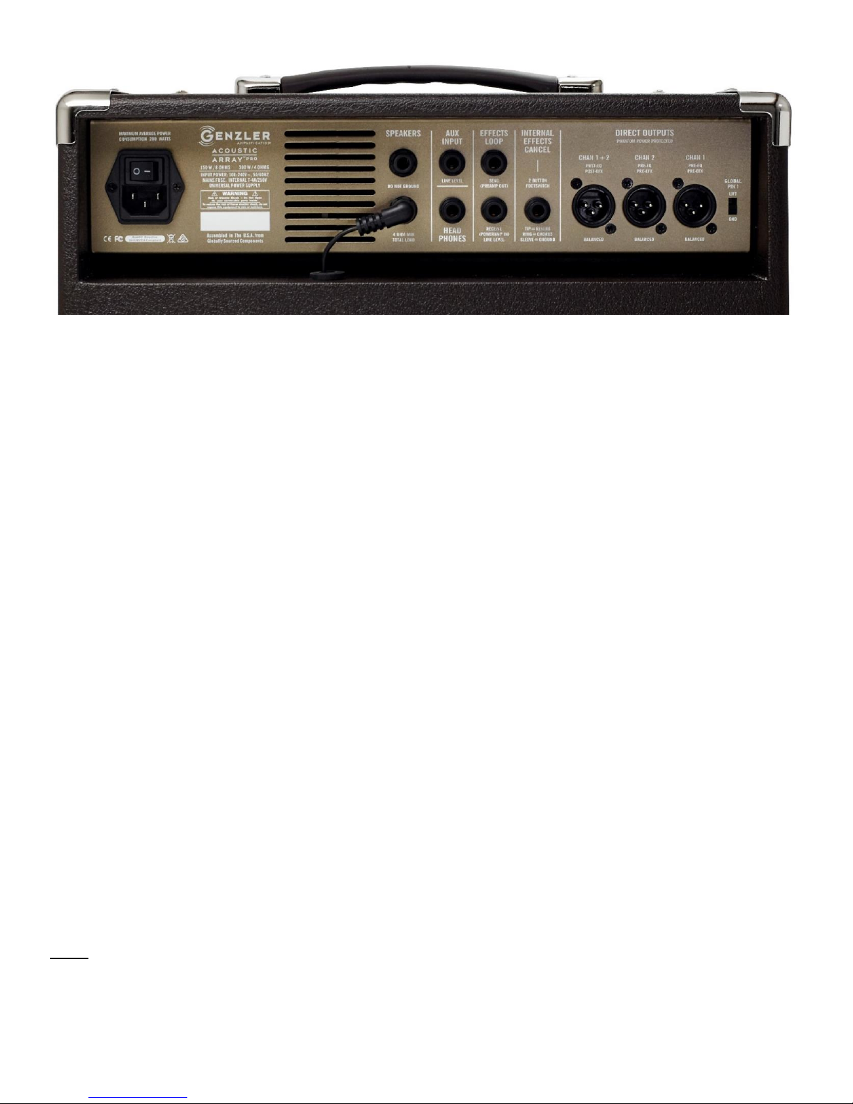
DIRECT OUTPUTS
– Three XLR balanced DIRECT OUTPUTS are provided for connection to PA systems, recording
interfaces, or external power amplifiers. CHAN 1 and CHAN 2 outputs are post-channel volume/pre-EQ/pre-effects (to
take advantage of the dual inputs on each channel) while the CHAN 1+2 output is pre-master volume/post-EQ/posteffects to aid in sending out a “finished” mixed signal. The DIRECT OUTPUTS signal grounds may be connected or lifted
using the GLOBAL PIN 1 switch. This switch lifts pin 1 on all of the DIRECT OUTPUTS to eliminate hum or buzz due to
ground loops between the
ACOUSTIC ARRAY™ PRO
and other equipment connected to the DIRECT OUTPUTS.
These outputs are fully protected against phantom power and may be used for driving lines of up to 300 feet.
INTERNAL EFFECTS CANCEL
– Either internal effect may be cancelled globally by connecting a standard 2 button
latching style footswitch with a ¼” TRS (tip/ring/sleeve) connector into this jack. Shorting the tip to the sleeve cancels the
Reverb, and shorting the ring to the sleeve cancels the Chorus. (Footswitch not included).
EFFECTS LOOP
– A rear panel effects loop (SEND and RECEIVE) is provided for connecting “serial” outboard devices
such as compressors and may also be used for parallel type outboard devices (delays, reverbs, harmonizers, octavers
etc.) by using the mix control located on the outboard device. This loop is located right before the MASTER VOLUME
control and is also intended as a Preamp Out / Power Amp In connection for possible “chaining” of amplifiers in a Master /
Slave configuration. The effects loop contains a “normal switch” in the RECEIVE jack that interrupts the signal path when
a plug is inserted into the RECEIVE jack. The SEND jack may be used for an aux. output without breaking the signal
path.
AUX INPUT
– A 1/4” stereo line level auxiliary input is provided that sums directly to the main output bus controlled by the
MASTER VOLUME control. This input is ideal for practicing or performing with recorded tracks from a CD player,
IPOD/IPAD, cell phone, or MP-3 player. This input is a tip-ring-sleeve type jack with built-in summing resistors that sum
left and right signals when used with a stereo cable. This input will also work with a mono tip-sleeve plug. Adjust the level
of the playback source to balance with the instrument’s volume.
HEAD PHONES
– A 1/4” TRS jack is provided for connection to headphones for silent practice use. Do not connect this
output to anything but headphones.
NOTE – For silent practice use, the combo’s internal speakers will need to be disconnected at the amplifier’s speaker
output jacks, however there is no danger in operating the amplifier without any type of speaker load connected.
Page 5
5
POWER AMPLIFIER
– The
ACOUSTIC ARRAY™ PRO
uses a state of the art, class D power amplifier design and a
high frequency auto-sensing universal switch-mode power supply (SMPS) to achieve unprecedented high performance
and lightweight packaging. For international use there are no voltage switches to change or jumpers to move. This
SMPS senses the line voltage from 100-240 Volts and automatically configures itself for the correct voltage. The
detachable mains IEC power cable with the proper plug configuration for the voltage source and country of operation is
required.
SPEAKER OUTPUTS
– The
ACOUSTIC ARRAY™ PRO
offers 2 paralleled ¼” speaker outputs. The combo speaker
load is 8 ohms and an additional 8 ohm cabinet may be added for a total load of 4 ohms, producing 300 watts of total
output.
POWER INLET CONNECTOR AND POWER SWITCH –
The
ACOUSTIC ARRAY™ PRO
utilizes a rear panel power
switch and power inlet connector. Use the correct mains IEC power cord required for the country where the amp is to be
used. The power supply auto-senses the correct voltage from 100V to 240 volts, 50 to 60 Hz for worldwide use.
NOTE – There is no externally accessible AC mains (line) fuse. The internal fuse is integral to the SMPS power supply
and is not user serviceable. This fuse will not fail except under very unlikely fault conditions to the SMPS. If this occurs a
qualified service technician is required to correct the problem.
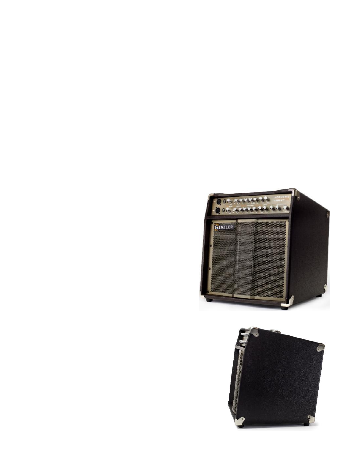
SPEAKER SYSTEM DESIGN –
The heart of the
ACOUSTIC
ARRAY™ PRO
design is the combination of a 10” woofer in a
ported chamber and an integrated 4 x 2.5” neodymium conedriver line array placed directly in front of the woofer. This allows
all of the audio to project from a single point source for a more
even and seamless projection of all frequencies. The response
benefits of this design are unparalleled clarity, definition and
detail, ideal for the complexity of the chords and tonal variations
of acoustic instruments. Additionally, because the array column
reproduces the mid and high frequencies without a tweeter, the
top end clarity is even, articulate and smooth – without excessive
hiss or harshness. Other major benefits of this design are
increased horizontal dispersion, more precise vertical pattern
control and deeper projection into the performance space.
CABINET DESIGN –
The
ACOUSTIC ARRAY™ PRO
offers a unique
cabinet shape that uses a 6-degree upward slant of the speaker baffle for
optimum projection and affords easy access to the control panel. This
cabinet shape is ideal for tight stages and provides superior audience
coverage. The cabinet is constructed of multi-layer poplar plywood
covered in an attractive dark brown/black vinyl and comes with nickel
corners and a soft molded strap handle. A metal speaker grille is used
with a center “pleat” to protect the line array speakers, and soft rubber feet
and a bottom mounted stand-adaptor round out the lower portion of the
cabinet.
Page 6
6
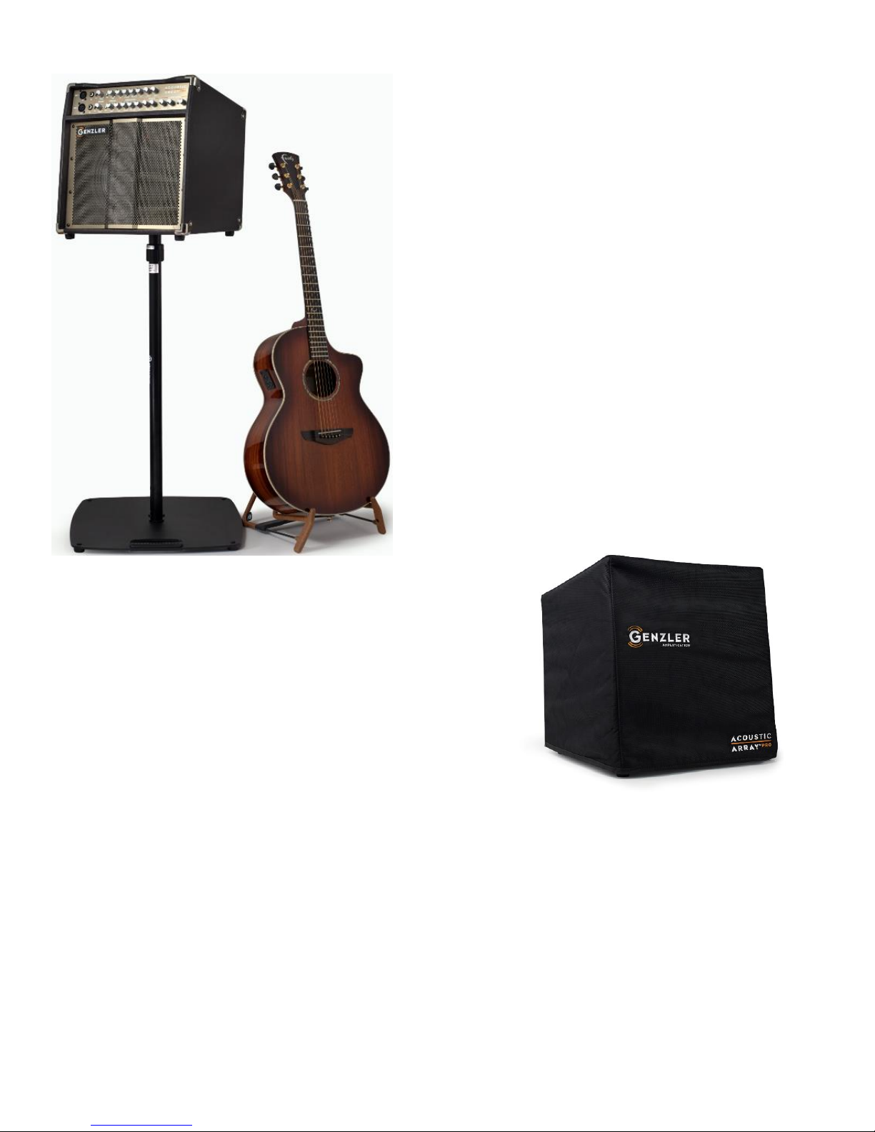
SPEAKER STAND MOUNTABLE –
The cabinet design offers a
35mm metal stand-mount socket in the bottom of the cabinet for
stable mounting to a speaker stand and extends the usability of
the
ACOUSTIC ARRAY™ PRO
as an acoustic PA. For many
performance venues this helps to get the projection of the speaker
system above the heads of the audience.
OPTIONAL COVER
– A heavy-duty padded cover is offered for full
protection while in transit. This is much more than a dust cover and
offers thick Cordova covering for protection against the elements and
heavy padding for the bangs and knocks of the road.
SPECIFICATIONS
ACOUSTIC ARRAY™ PRO
Rated Power: 150 watts @ 8 ohms; 300 watts @ 4 ohms
Speaker System Freq. Response: 60 - 20KHz
Dimensions: 16.75” H x 15.75” W x 13.75” D
Weight: 27 lbs
Product Type: Audio Amplifier
Product Name:
ACOUSTIC ARRAY™ PRO
Model Number: AA-PRO (all versions)
Operating Power Condition: 100~240V, 50/60 Hz
Effective Date: 11/01/2017
Page 7

7
SAFE OPERATING REQUIREMENTS:
• Never set an amplifier on anything that will tip over or collapse under its weight.
• Provide a minimum distance of 1 inch (25.4mm) around all sides of the amplifier for sufficient ventilation. The
ventilation should not be impeded by covering the amplifier’s vent openings with items such as newspapers, tablecloths,
curtains, etc.
• No naked flame sources, such as lighted candles, should be placed on the
ACOUSTIC ARRAY™ PRO
amplifier.
• This amplifier should not be exposed to dripping or splashing and no objects filled with liquids, such as vases or drinks,
should be placed on this product.
• The
ACOUSTIC ARRAY™ PRO
amplifier should be connected to a mains outlet (power receptacle) with a protective
earth (ground) connection at all times.
• The amplifier’s mains plug (power plug) is considered the disconnect device and the connection must remain accessible
at all times.
• This amplifier is capable of producing sound pressure levels that may cause hearing loss.
• There are no user serviceable parts and hazardous operating voltages are present inside this unit. Always consult a
qualified repair facility for service.
WARNING!
• The use and operation of this device constitutes an agreement of full release of any and all liability connected with its
use. Only persons familiar with the operation of high-powered professional audio equipment should attempt to operate
this device.
• In addition, by use of this device, the user agrees to hold
GENZLER® AMPLIFICATION
and its designers, sales agents
and all other affiliates and related parties harmless in the event of any accident, injury, damage, or loss resulting from
such use.
• Manufacturer’s sole responsibility is to provide a warranty on the specified performance of the product under normal
operating conditions for a period of 3 years.
WARRANTY:
•
GENZLER® AMPLIFICATION
warrants the
ACOUSTIC ARRAY™ PRO
to be free from defects in materials and
workmanship for a period of 3 years from the date of purchase, when purchased from an authorized
GENZLER
®
AMPLIFICATION
dealer.
• This warranty does not cover normal wear and tear incurred from the normal designed use of the product.
• This warranty is effective only if a copy of the original sales receipt is presented at the time of warranty service.
• All warranty service must be performed by a
GENZLER
®
AMPLIFICATION
authorized service center.
• Before returning any unit for service, a returned merchandise authorization number (RMA#) must be obtained by
emailing [email protected].
• This warranty is valid in the US & Canada only. For all products sold outside the US, warranty is handled through our
international dealer or distributor for that country.
• All warranty registration must be completed on our website. We request that warranty registration be completed within
10 days of purchase.
• For complete warranty information and registration visit:
www.GENZLERAMPLIFICATION.com.
GENZLER® AMPLIFICATION LLC
BROOKLYN, NY 11215 U.S.A.
Email: [email protected]
Form: AA-PRO-OM-REV1
 Loading...