

UHF RFID Reader
Max Faster GVR9040
User Guide
Model: Max Faster GVR9040
FCC ID: 2AL59GVR9040

Max Faster GVR9040 User Guide
Catalog
1 Introduction to Max Faster GVR9040 ............................................................................................ 2
1.1 Product Parameters................................................................................................................. 2
1.2 Feature .................................................................................................................................... 3
2 Installation....................................................................................................................................... 5
2.1 System Composition ............................................................................................................. 5
2.2 Interfaces ............................................................................................................................... 6
2.3 Mounting the Reader ........................................................................................................... 6
2.4 Connecting the Reader ........................................................................................................ 9
2.5 Reader-Backend Communication Procedure ......................................................................... 9
3 Operation ..................................................................................................................................... 10
3.1 Equipment Connection ...................................................................................................... 10
3.2 RF Configuration ............................................................................................................... 11
3.3 Tag Inventory ...................................................................................................................... 13
3.4 Upgrading ........................................................................................................................... 14
4 Safety Instruction ........................................................................................................................ 16
5 FCC Warning ................................................................................................................................ 17
1
Max Faster GVR9040 User Guide
Wireless Link Characteristics
Parameters
Specifications
Air Interface Protocol
ISO/IEC18000-6C/63
EPC Global Gen2 V1 and V2
Supported Regions
902MHz~928MHz;
Other frequency ranges can be customized.
Data encoding
FM0、Miller
BLF
64~640 KHz
Electrical and Application Characteristics
Parameters
Specifications
Power supply
AC 100~220V,50~60Hz
Communication interface
10/100M FE;RS-485;
Antenna ports
4 N-type Female
GPIO interface
4 GPIO
1 Introduction to Max Faster GVR9040
Max Faster GVR9040 is a stationary, four-port, UHF Reader, which is designed to support the EPC
Class 1 Gen 2 (ISO 18000-6C/63) protocol. It has unparalleled advantages in providing high
identification accuracy under long distance and fast speed. Its strong anti-interference features can
adapt to complex electromagnetic environment, especially in the intelligent traffic management,
logistics, mobile asset management, and other applications.
The reader is designed for indoor and outdoor environment and delivers high performance under
challenging circumstances, such as fast vehicle speed and extreme temperature. Therefore this
equipment is ideal for commercial and industrial applications.
1.1 Product Parameters
2
Max Faster GVR9040 User Guide
Control mode
Trigger/continuous
WiFi
Optional
4G
Optional
Applicable Characteristics
Parameters
Specifications
Protection grade
IP65
Working temperature
-40℃ ~ +75℃
Storage temperature
-40℃ ~ +85℃
Working humidity
5%~ 95% RH
Mechanical Characteristics
Parameters
Specifications
Dimension
361mm×287mm×110mm
Weight
6.5kg
Case material
Aluminum alloy
Case color
Gray
Mounting position
Gantry or roadside pole
Mounting mode
Cantilever type, gantry type, pole type
1.2 Feature
Multi-channel support: with 4 N-type RF interfaces, it supports radio communication in multiple channels
and the co-function of 4 antennas.
Wide application: support frequencies ranging from EPC C1Gen2 860MHz to 960MHz.
Powerful Function: support device self-test to accurately detect its operation status; support intelligent
temperature modification to stabilize the power output within the changes of ±1dBm; support remote update,
centralized monitoring and control; support data storage up to 512MB, and offline cache of over 500,000
transaction entries.
3

Max Faster GVR9040 User Guide
Premium Performance:
By adopting our patent technology -- multi-mode adaptive interference cancellation and suppression, it
can automatically eliminate the interference outside the antenna;
With high-standard receiving sensitivity, it guarantees the reception quality of tag identification;
The employment of multi-core high-speed host CUP and Linux system enable its strong processing
capability;
Stability and Reliability: by employing industrial high-speed processor, advanced software radio engine
and carrier cancellation technology, it has strong anti-interference capability and IP65 protection level.
High-speed Identification: tag identification speed reaches 1000 times/s.
4
Max Faster GVR9040 User Guide
2 Installation
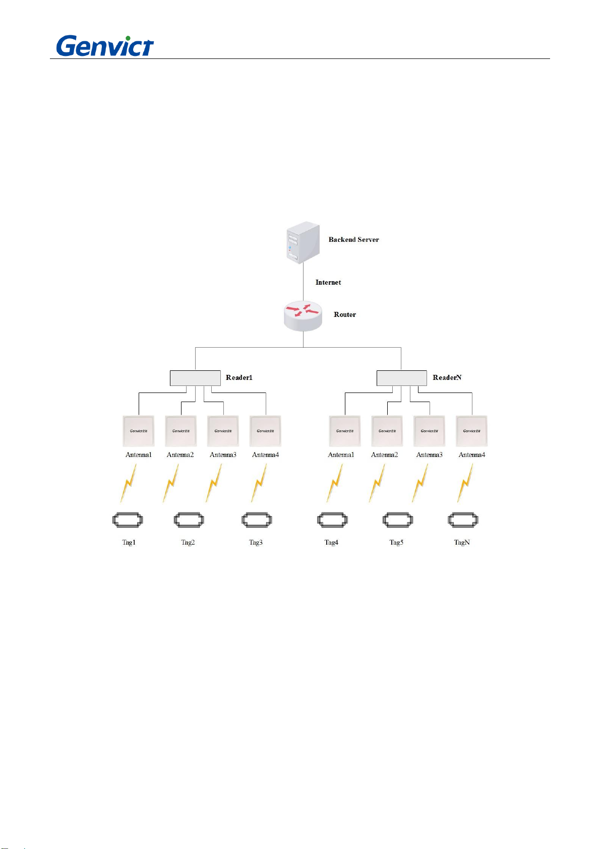
2.1 System Composition
The application system is mainly composed of UHF Tag, antenna, reader (interrogator) as well as the
backend system (including server, router, etc.), the figure is as follow:
Figure 1 Application System
Equipment Functions are as follows:
Tag: store identification information, etc.
Antenna: signal conversion for interactive communication between reader and tag.
Reader (Interrogator): it can be installed in the pole or beam. Through wireless communication between
antenna and tag, the tag data can be acquired and transmitted to the backend server.
Router: support Ethernet network connection of the reader (Interrogator).
Backend server: used for reader configuration, monitoring and management; the tag data can be acquired by the
reader and thus forming the data record.
5

Max Faster GVR9040 User Guide
Item
Unit
Quantity
Remark
2.2 Interfaces
Interfaces include: power interface, GPIO, Ethernet, RS-485, status indicator, RF port, 4G and WIFI
ports.
The schematic diagram of interface panel is shown in the following figure:
Figure 2 The Schematic Diagram of Interface Panel
(1) AV220V: support external power input;
(2) Waterproof port;
(3) Status indicator: red light, yellow light and green light;
(4) Communication port: including Ethernet 10/100 Base-T; and RS-485: full duplex, default
19200bps;
(5) Antenna port: 4 N-type female RF connectors;
(6) 4G port;
(7) WIFI port;
2.3 Mounting the Reader
Bracket accessories are used to install reader. It consists of one bracket FN4, one bracket FN6 and
four sets of M10*240 bolt assemblies.
Table 1 List of Bracket Accessories
6

Bracket FN4
PCS
1
Bracket FN6
PCS
1
M10*240 bolt assemblies
Set
4
Figure 3 Bracket FN4
Max Faster GVR9040 User Guide
Figure 4 Bracket FN6
Fix bracket FN4 and bracket FN6 at the appropriate position on the pole by using four sets of
M10*240 bolt assemblies:
7

Max Faster GVR9040 User Guide
Figure 5 Bracket Installation
Insert the bolt of the bracket FN6 into the holes on both sides of the reader, and then tighten the cap
nuts:
Figure 6 Equipment Installation
The power and digital signal cables are shown in the following figures.
8

Max Faster GVR9040 User Guide
Figure 7 Power Cable Figure 8 Digital Signal Cable
2.4 Connecting the Reader
The Max Faster GVR9040 reader gives priority to network interface for device communication. The
device is connected to the network device or PC via the dedicated communication cable as shown in
the following figure:
Figure 9 The Diagram of Equipment Connection
2.5 Reader-Backend Communication Procedure
The application flow of reader and upper computer at the backend is shown in the figure below:
The reader receives the control instructions from the upper computer;
The reader receives the instruction to carry out data processing and then returns the operation
result to the upper computer;
The reader processes the received response signal and presents the relevant tag data to the user.
9

Max Faster GVR9040 User Guide
Figure10 The Reader-Backend Communication Procedure
3 Operation
The reader supports the Low Level Reader Protocol (LLPR), but when carrying out equipment
function test, specific operation process is conducted as follows.
3.1 Equipment Connection
By default, the reader connects the device through the network cable. The default IP is 192.168.5.245.
For devices with modified IP, the changed IP is used to connect. If the IP address is forgotten, scanning
tool can be used to obtain IP address information.
When opening the upper computer for the first time, user need to select the network card which
corresponds to the local IP address of the same network segment. The upper computer should be
restarted for the configuration to take effect. Click “Scanning”, select the IP address of scanned device
or enter the IP address manually, then the reader is connected. After the upper computer is successfully
connected, the log info at the bottom will notify its connection success.
10

Max Faster GVR9040 User Guide
Figure 11 Connection Interface
3.2 RF Configuration
The parameter configuration mainly involves the number of antennas, antenna No., transmitting power,
encoding mode, reverse data rate and the selection of fixed or hopping frequency. Each parameter has
a separate communication interface to facilitate testing. The specific configuration is described below.
3.2.1 Antenna Configuration
The reader supports maximal four antennas to work at the same time. The number of antennas and the
corresponding antenna port will be configured according to the actual application. Before configuring
the antenna, it is necessary to ensure that corresponding antenna port has been connected with the
antenna or is loaded. Otherwise, the antenna port will not open.
11

Max Faster GVR9040 User Guide
Figure 12 Antenna Configuration
3.2.2 Transmitting Power Configuration
The reader supports the configuration and query of transmitting power ranging from 15dBm to
33dBm.
Figure 13 Transmitting Power Configuration
3.2.3 Frequency Configuration
The working frequency ranges from 902.75MHz to 927.25MHz. A total of 50 frequency points can be
set up and queried.
Figure 14 Frequency Configuration
3.2.4 Hopping Mode Configuration
Select frequency hopping as “Open” and click “Set up” to configure the reader to work in frequency
hopping mode. The default frequency hopping interval is 400ms, and the frequency hopping points are
50 frequency points from 902.75MHz to 927.25MHz. When the frequency hopping is selected as
“Close”, the reader works in fixed frequency mode, and its working frequency point is set by the
frequency point configuration.
12

Max Faster GVR9040 User Guide
Figure 15 Hopping Mode Configuration
3.2.5 Reverse Data Rate Configuration
The reader supports the decoding of tag response data in the reverse rate ranging from 64K to 640K.
The reverse data rate configuration tells the reader which reverse rate is currently in use for correct
decoding.
Figure 16 Reverse Data Rate Configuration
3.2.6 Encoding Mode Configuration
Reader is set to support decoding with FM0, specifically M2, M4 and M8 encoding data. The
encoding mode configuration is used to inform the reader current encoding mode for correct decoding.
Figure 17 Encoding Mode Configuration
3.2.7 Carrier Switch Configuration
When the carrier is turned on, the power can be output at the corresponding antenna port in
accordance with the previously configured transmitting power, provided that the corresponding port is
connected with the antenna or is loaded, otherwise it will be notified that the carrier fails to be turned
on.
Figure 18 Carrier Switch Configuration
3.3 Tag Inventory
Tag inventory is the core function of the reader. Tag inventory test can be carried out once the RF
parameters are configured as above. First switch to “Tag Inventory” page, then click “Inventory”. The
tag number, tag data, corresponding antenna port, inventory time and other data will then be reported.
The inventory result is shown in Figure 20.
13

Figure 19 Tag Inventory Page
Max Faster GVR9040 User Guide
Figure 20 Inventory Result
3.4 Upgrading
The reader supports upgrade via web page. It can be logged in by entering the device IP address after opening
the browser. The default device IP is 192.168.5.245.
Select “App Upgrade” on top, click “Browse” to select the upgrade package file, and then click “Upgrade”. An
upgrade success notification box will pop up once upgrade is completed. The device will then automatically
restart. The whole upgrading process is completed once the buzzer beeps again.
14

Figure 21 Web Log-in Page
Max Faster GVR9040 User Guide
Figure 22 Web Upgrade Page
15

Max Faster GVR9040 User Guide
4 Safety Instruction
User Requirement
Please keep the equipment installed vertically or in steady place to prevent it from falling.
Use the equipment only within the rated input and output range.
Do not disassemble the equipment.
Transport, use, and store the equipment within the permissible humidity and temperature
range.
This product must be installed by a professional installer, and non-professionals should not
install or disassemble it at will.
Power Requirement
Different power cables are recommended in accordance with regions, and shall be used
within its rated specifications.
Connect the Class I equipment to the socket with ground protection.
The power supply should be within the rated voltage. The specific requirements can be
checked on the nameplate on the right side of the equipment.
The reader may be exposed in the outdoor environment for a long time. Therefore, working
procedures must be strictly conducted in the assembly, sealing and installation process to guarantee its
waterproof level. In addition, the equipment casing should be grounded through thick wires to prevent
lightning damage.
16

Max Faster GVR9040 User Guide
5 FCC Warning
This device complies with part 15 of the FCC Rules. Operation is subject to the following two
conditions: (1) This device may not cause harmful interference, and (2) this device must accept any
interference received, including interference that may cause undesired operation.
Any Changes or modifications not expressly approved by the party responsible for compliance could
void the user's authority to operate the equipment.
Note: This equipment has been tested and found to comply with the limits for a Class B digital device,
pursuant to part 15 of the FCC Rules. These limits are designed to provide reasonable protection
against harmful interference in a residential installation. This equipment generates uses and can
radiate radio frequency energy and, if not installed and used in accordance with the instructions, may
cause harmful interference to radio communications. However, there is no guarantee that interference
will not occur in a particular installation. If this equipment does cause harmful interference to radio or
television reception, which can be determined by turning the equipment off and on, the user is
encouraged to try to correct the interference by one or more of the following measures:
-Reorient or relocate the receiving antenna.
-Increase the separation between the equipment and receiver.
-Connect the equipment into an outlet on a circuit different from that to which the receiver is
connected.
-Consult the dealer or an experienced radio/TV technician for help.
*RF warning for Mobile device:
This equipment complies with FCC radiation exposure limits set forth for an uncontrolled
environment. This equipment should be installed and operated with minimum distance 20cm between
the radiator & your body.
17
 Loading...