


OPERATING
INSTRUCTIONS
OPTIMA 260 – ECO 190, ECO 375

2
TABLE OF CONTENTS
1. Installation of Optima 100 Design ...............................................................................................................................3
2. Installation of Optima 100 Opus ...................................................................................................................................4
3. Operation ...............................................................................................................................................................................5
4. Data Logger ...........................................................................................................................................................................5
5. Genlog Set Points ................................................................................................................................................................9
6. Function ............................................................................................................................................................................... 16
7. Maintenance .......................................................................................................................................................................17
8. Troubleshooting ................................................................................................................................................................ 18
9. Table of Factory Settings .............................................................................................................................................. 19

3
1. INSTALLATION OF OPTIMA 100 DESIGN
1.1 Installation of the Control Panel
The control panel is designed to be mounted onto
a level wall.
1.2 Installation
Find the installation place for the control panel, mark off
the holes and screw the fixture securely onto the wall.
Use at least 4 screws for securing the panel, two at the
top and two at the bottom.
Obligatory screw
Obligatory screw
Obligatory screw
Obligatory screw
Screw
Screw
Hold up the wall frame against the wall and mark off the
holes for fastening the frame. Drilling of holes, hole size
and suitable screws for fixing the panel all depend on the
wall material.
Place the control panel in the fixtures and tilt it in against
the wall. The four support points in the corners of the
display must touch the wall to keep the display stable.
A
Support
point
Support
point
Support
point
Support
point
Underneath the control panel there is access for the:
A: Terminal block. Connection to main circuit board
Fit a 8 x 0.25 mm
2
low-current cable between the unit and
the control panel. The maximum cable length is 50 m.
The voltage drop for cable lengths over 50 m is too high
and can cause operating errors.
Method of Installation of the Wall Fixture
First screw the fixture securely onto a level wall and then
guide the cable visibly up from below.
Connect the low-current cable to the terminal block.
Check that the cable is connected to the same
numbers at both ends.
(Between the control panel and the main circuit
board in the unit.)
Clip the control panel to the wall fixture by guiding it down
from above, slightly slanting out at the bottom. Finish by
pressing it in at the bottom so that it is flat against the wall.
To disassemble, pull the control panel slightly slanting out
at the bottom and lift up.
Pos. Description
1 Panel housing
2 Front of panel
3 Pressure plate for display
4 Wall fixture
5 Glass for the display

4
2.1 Installation of the Control Panel
The control panel is designed for being mounted to an Opus
type power socket.
2.2 Installation
Find the installation place for the control panel,
connect the wires and click the control panel into place.
Fit a 8 x 0.25 mm2 low-current cable between the
ventilation unit print circuit board and the control panel.
The maximum cable length is 50 m.
The voltage drop for cable lengths over 50 m is too high and
can cause operating errors.
Check that the low-current cable is connected to the same
numbers at both ends. (Between the control panel and the
main circuit board in the unit.)
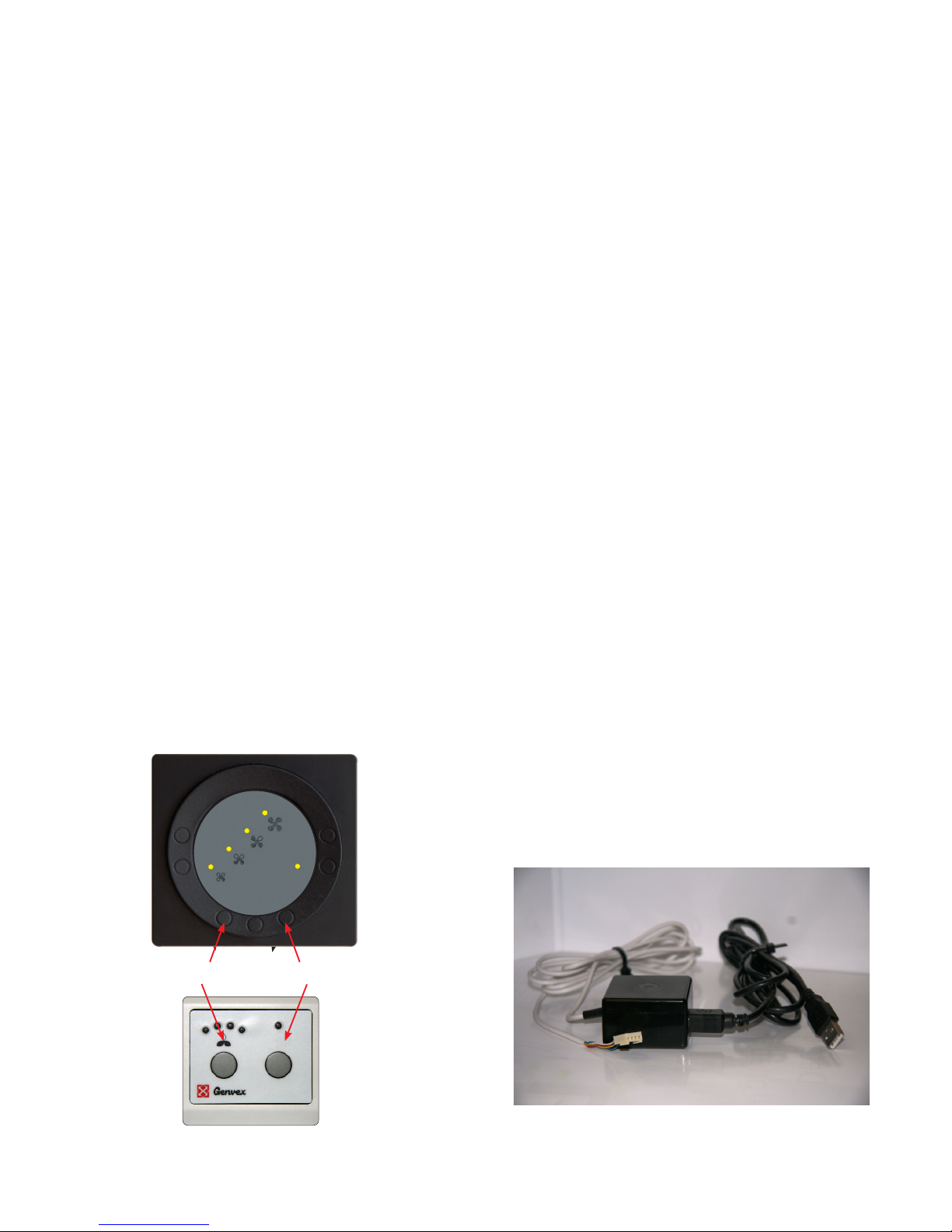
The key on the left of the control panel is K3, and the key on
the right of the control panel is K5.
2. INSTALLATION OF OPTIMA 100 OPUS
5
4. DATA LOGGER3. OPERATION
Genvex item no. 022031
– USB/Optima communication cable for PC
Data logging equipment
There are two ways to adjust set points and program the
Optima 260 control system.
1. Programming via Genvex Genlog software using a USB
connected to the Optima 260 main circuit board.
2. Programming via Genvex Genlog software and
outputting set points to the SD card. (Use the "save to
SD card" function in the Set Point Management menu.)
Note on method 1
To be able to initiate communication with Optima 260,
use data logger equipment with a 4-pin connector.
Connect the 4-pin connector to the main circuit board
and the USB connector to the PC. These are accessories
that can be purchased directly from Genvex.
Note on method 2
To use method 2 to initialise a Genvex unit with an
Optima 260 control system, we recommend that you
remove the SD card of the main circuit board again after
starting up the unit (start-up and input of data take
approx. 2 minutes) as Optima 260 will input the
preprogrammed data on the SD card every time there
is a power outage. You can replace with advantage the
programming SD card with an empty SD card in order to
take advantage of the automatic data logging feature.
The latest version of the Genvex Genlog software can be
ordered from Genvex by telephone +45 73532700.
1
2
3
4
K3 K5
All Genvex ventilation units with Optima 260 control
system can be operated with an Optima 100 display.
The Optima 100 control system has the following
setup options:
• Fan speed
• Filter alarm
• Reheater activation/deactivation
The control system comes factory-preset, which means that
the unit can be put into operation without changing
the operating settings. The factory setting is only a basic
setting that can be adapted to the operating desires and
demands for the dwelling in question to make it possible to
achieve optimal utilisation and operation for the system.
3.1 Operating and Changing Settings
Optima 100 Design is operated with the K3 and K5 keys.
Optima 100 Opus is operated with the K3 and K5 keys.
The K3 key is used to change fan speed. To turn off the
ventilation unit, press and hold the K3 key for approx.
5 seconds (the unit will shut down after an afterflow period
of approx. 3 minutes).
Note: the "turn off ventilation" feature must first be
enabled in the control system via Genlog.
The K5 key is used to reset the filter alarm (press and hold
for 10 seconds). Individual push of the key activates/
deactivates a possible electric reheater, if mounted.

6
Functional Description of Data Logger
The data logger software is designed for configuring and
monitoring Genvex devices. The data logger can be
connected to all Genvex Optima control systems.
The instructions presuppose a correct and
functioning setup of the software.
The user interface in Genvex Data Logger
The data logger can be used for several different purposes:
Setup of parameters in the control system.
Setup and changes to the clock program in the control system.
Reading of the data logger in the control system for the
past three years.
“Live” logging of the current operation of the device.
Subsequent analysis of the operation of a device.
User interface
The program is structured with the primary image in the
middle of the screen. This is where the graphs that
represent the information collected from the control
system are displayed. The menu line for the various
settings is placed at the top.
Values that are read “here and now” or values that lie below
the read line are displayed on the left side. The red line
appears when you click a random place on the display.
The figures in the left column will then represent all the
values that lie on the line. The colours of the curves in the
logging area correspond to the colours displayed on the
left-hand side. The exact time of logging will be displayed
in the field at the very bottom.
Tip: Click on the clock field to change the field to display
“LOG NO.”. This can be useful if you want to refer to a
certain logging.
There is an area with grey and white lines at the top of the
logging area itself on the screen. These lines will be red if
relay function is active. Hold the mouse cursor over
the line for a moment, and a small help text will appear.
The left y-axis is a scale for temperatures. The right-hand
side of the logging area is the scale for percentages, e.g.
for fan speeds. The x-axis represents the time line.
A logging can contain a good many pages. This is why
there is a page number in the right/left corner next to the
red arrows. To flip between pages, click the red arrows.
Press and hold the left mouse button for a moment over
the red arrow to open a dialogue box. Here you can enter
the page number you want to scroll to.
There is a status menu located at the bottom of the
screen. This line displays the date and time, if the data
logging has started or stopped, the number of data log
files and which control system the software is
configured for (this is changed in “Settings”).
Menus
Files
Retrieve data*
– Retrieves data saved previously on the hard drive (.txt files)
Import of SD card files* – Imports data saved on the
Optima Design control panel (.dal files)
Save data – Saves the current logging
Save window – Saves only the current window
Save data Excel – save the data to comma separated
value file
Print – Prints the current window
Exit – Exits the software
*The data logger works with .txt files, whereas the control panel works
with .dal files.
View
View graphs – Opens a check box. This provides the
opportunity to select or deselect the graphs displayed
on the screen, usually to provide an overview.

7
Zoom – Makes the picture larger or smaller.
View average – Makes it possible to view an average of
the graphs in the selected window.
Functions
Start logging (20 sec.) – Opens a dialogue box for
inputting file name. It can be very advantageous to add
the Optima version to the name, e.g. by writing Opt310 as
part of the name. Then start a new logging from the
control panel. The logging is taken every 20 seconds and
is then displayed on the screen. After a while, the logging
will begin to form an image. If you do not click on the
image to generate the red line, the values on the left side
will refer to the last logging.
Stop logging (20 sec.)
Stops the logging. The display on the screen is saved
automatically.
One logging
Only performs a single logging. Not saved automatically.
Comments on data
Here you can add comments on a logging.
Delete data
Here you can delete data.
High-speed data logging (2 sec.)
Not saved in a file. Used for monitoring only.
Data from Control System
Set points in control system – Opens the following box.
Here it is possible to retrieve all set points from the
microchip or control panel, change them and then export
them back to the microchip or control panel.
Clock/week program in control system – Opens the
following box.
This program makes it easier and clearer to create the
clock program in Optima. Select the day of the week
which will be programmed by clicking on it. The day
selected in the example is Monday. Create the clock
program for Monday by using arrow-up and arrow-down
in the lowermost window, immediately to the left of the
buttons for the weekdays.
Select 1, 2, 3 or 4 underneath fanspeed level. To skip an
item, select 0. To stop the ventilation unit, select 4.
Once the clock program for the selected day has been
created, the day can be copied to the other days by
clicking on the day of the week.
The buttons on the right side of the window are used for
receiving and sending the change times to and from the
control panel and for downloading and saving the clock
program on the hard drive.
“Exit” "closes the window.
8
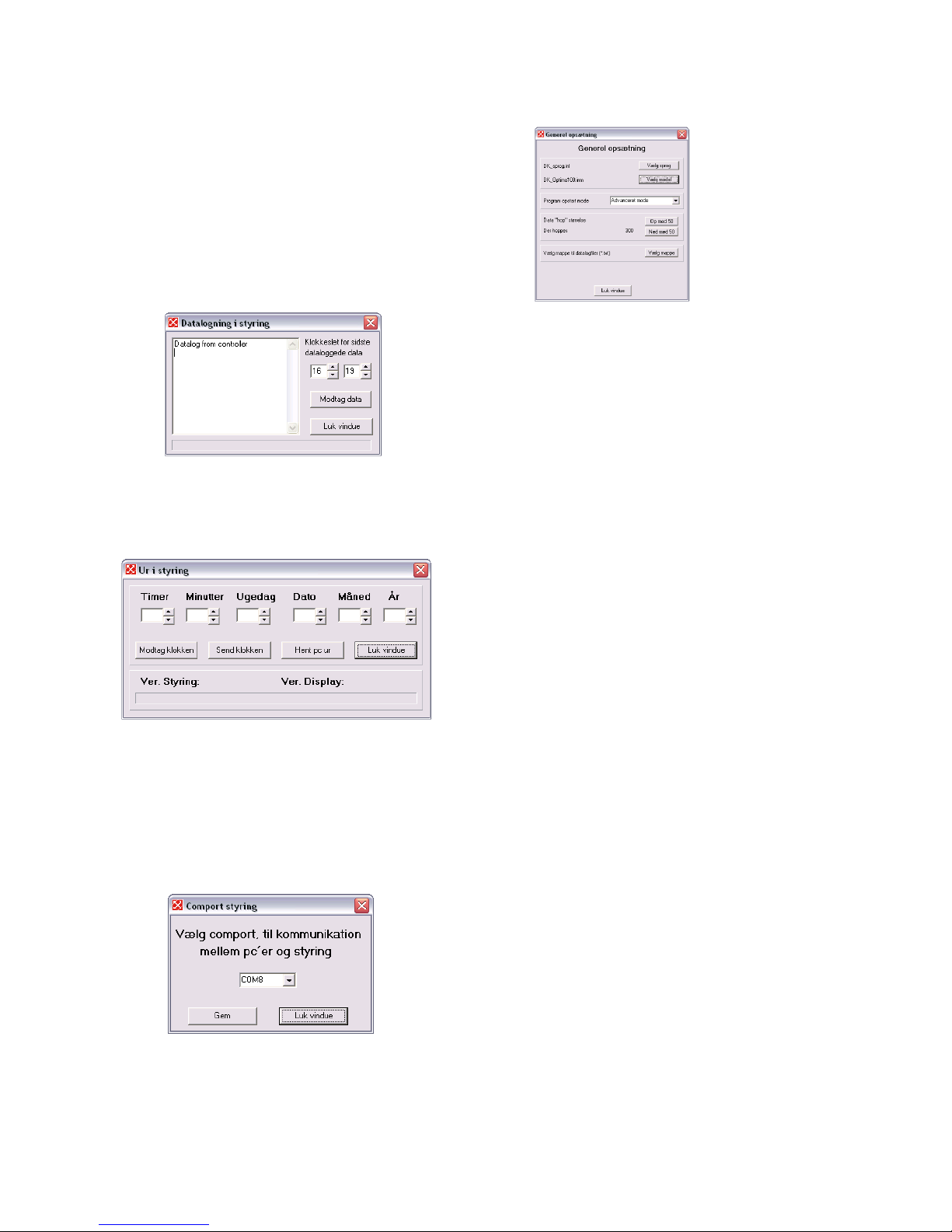
Data logging in control system (not for systems with SD
card for datalog) – Here you can retrieve the saved logging
in the control panel to the program. Change the time, if
possible, if the time of the last logging deviates from the
selected time. This is done out of consideration for the time
line at the bottom of the screen. This can be relevant, for
example, if the logging is retrieved from a transmitted
loose SD card or the like.
Click on “Receive data” to input the data. Note that this can
take up to 10 minutes. While the data is being loaded,
the control panel and the control system of the device will
not be able to communicate.
Clock in control system – An easy way to set the clock in
the control system.
Settings
Comport control – Here you select the Comport which will
be used for the data logger.
General setup – Here you can choose language,
model as well as folder for the log files.
For instance, it can be a good idea to create a folder for
logs under “Documents” and set up the program to suggest
this folder as default.
General Information
Note that:
• Loggings are not linked to setup. In other words, even if
the loggings are retrieved from the hard drive or the
control panel, they do not necessarily match the selected
control system. You therefore run the risk of analysing a
logging from a Combi, but viewing the values as if they
come from an Energy.
• The software is set up by default in Danish. This can be
changed in “Settings”.
• Certain antivirus programs will regard the log files as
viruses when they are sent by email.
Connection to PC – Optima 260
In order for the Optima 260 to be able to communicate
directly with the Genlog software, use data logger
equipment that can be connected directly to the Optima
260 printed circuit board. For details see page 5.

9
5. GENLOG SET POINTS
Calendar
Use this function to configure the setting for each day of
the week. Each day can be configured to run with different
fan speeds, as required. You can copy the configuration
from one day to another. Here you can choose ON or OFF.
If, for example, there is nobody home for some time, the
daily settings can be turned off and the system will run
according to a manual setting, e.g. level 1.
01 – Calendar
Choose between controlling the system manually or
controlling the speed (air exchange) and temperature
automatically according to a fixed weekday program.
If the menu item is set to OFF, the system will be controlled
manually according to the speed and temperature selected.
If the menu item is set to ON, the system will be controlled
according to the day programs entered in menu items 02 to
08.
Setting option: ON/OFF.
Example: Monday
Up to 10 switching times can be entered for one day.
The times can be entered in a random order. Enter hours
in the first, minutes in the second and speed in the third
column. Use the fourth column to enter the temperature
difference with which the temperature should be lowered.
Example: If the temperature is set to 21°C and you enter –
2.0°C, the system will aim at 19°C.
If the speed has been changed manually with the key under
daily operation, the program will return to the weekday
program once the next switching time has been passed.
Examples of a weekday program:
01 07:30 H3 -0.0
02 09:15 H1 -1.0
03 17:00 H3 -0.0
04 18:00 H2 -0.0
05 23:30 H2 -2.0
It is not necessary to use all switching times. If the line is
marked with 0, the control system will skip it.
Thursday to Sunday:
These days can be filled in individually in the same way as
under the example for Monday.
User menu
01 - Temperature
Set your desired temperature between 10 and 30°C.
Item 19 of the Service menu allows you to choose
between supply air regulation or extract air regulation.
Setting option: between 10 and 30°C.
02 - Preheating
If a preheater is fitted to the outdoor air duct, the set point
must be configured to ON. Enter the desired preheating
temperature in item 20 of the Service Menu. If a refrigerant
device is installed in the supply air duct instead, the set
point must be set to OFF. (It is not possible to control a
preheater and a refrigerant device at the same time).
If both types of optional equipment are installed, the set
point must be configured manually in the spring and in the
autumn. If none of the help functions in item 27 of the
Service Menu are used, help function 4 can be used to
control the additional cooling.
Setting option: ON/OFF.
03 - Reheating
If there is a reheater fitted to the system, you can choose if
the reheater should operate. If the set point is set to OFF,
the heater will not operate, even when this is necessary. If
the set point is set to ON, the heater will start, as required.
It regulates in accordance with the temperature set in item
1 of the User Menu.
Setting option: ON/OFF.
04 - Timer levels 3 and 4
At speeds 3 and 4, the system will automatically reconnect
to speed 2 after the number of hours set in item 17 of the
Service Menu by setting the set point to ON. If the set point
is set to OFF, the system will run at speed 3 or 4 until it is
manually changed to another speed.
Setting option: ON/OFF.
Monday 1
Tuesday 2
Wednesday 3
Thursday 4
Friday 5
Saturday 6
Sunday 7
Weekday
January 1
February 2
March 3
April 4
May 5
June 6
July 7
August 8
September 9
October 10
November 11
December 12
Month

10
05 – Change filter
There is a built-in filter timer which counts how long the
system has been running since the last change of filter.
The set point can be set between 1-12, which corresponds to
12 months. It is recommended that the set point be initially
set to 3, which corresponds to 3 months (if 0 is entered,
the filter timer is off and will not give filter warning).
If the filters are too dirty after the set period, set the set
point to a lower number. If it is not necessary to change the
filters after the configured period, the set point can be set
to a higher number.
When the timer reaches the set value for filter change,
the filter change alarm will flash on the display.
Once the filters are changed, return to the screen with the
daily operating options and press and hold down the filter
indicator key until the diode switches off. The device will
then change back to normal operation.
Setting option: between 1 and 12 months. set point = 0 will
disable the filter timer (Be careful when using this setting –
Genvex disclaims any responsibility for faults in the
ventilation unit caused by a clogged filter).
06 – Humidity control
Here you turn on humidity control. It must be set to ON in
order to be active.
Setting option: ON/OFF.
Service Menu
10 – Level 1 Supply air
Level 1, which is the lowest speed, is usually used when there
is nobody home. Both fans can be configured independently
of each other for all levels so that the air flow in the supply
air and in the extract air is equal, which provides optimal
operation.
The adjustment of the system must be performed with
specialised air measuring equipment and can be done
without using the main regulating damper.
Configuring the air flows without expert advice is not
recommended. Incorrect configuration can lead to major
energy consumption or unpleasant indoor climate.
Setting option: between 0 and 100%.
11 – Level 2 Supply air
Level 2 is the recommended speed of the system for
providing optimal indoor climate. It should be adjusted to the
ventilation requirement of the dwelling.
Setting option: between 0 and 100%.
12 – Levels 3 and 4 Supply air
Level 3 is the highest speed that can be configured.
It is used, e.g. if there are many guests or there is a
lot of activity in the kitchen.
Setting option for level 3: between 0 and 100%.
Factory setting for level 3: 75%.
Level 4 is used mainly in the summer for lowering indoor
temperature. Remember that a higher air exchange rate
increases energy consumption.
Setting option for level 4: Cannot be configured.
13 – Level 1 Extract air
The fan speed is adjusted until the same air flow is achieved
as the supply air on level 1.
Setting option: between 0 and 100%.
14 – Level 2 Extract air
The fan speed is adjusted until the same air flow is achieved
as the supply air on level 2.
Setting option: between 0 and 100%.
15 – Levels 3 and 4 Extract air
The air flow of level 3 is adjusted to the same air flow as the
supply air on levels 3 and 4 (item 12).
Setting option for level 3: between 0 and 100%.
Factory setting for level 3: 75%.
Setting option for level 4: Cannot be configured.
16 – Not relevant
17 – Timer levels 3 and 4
If automatic reconnection is used for speeds 3 or 4, you can
enter how many hours the system should run on level 3 or 4
before it automatically returns to level 2. The set point can
be configured to between 1 and 9 hours.
Setting option: between 1 and 9 hours.
18 – Filter/stop
To ensure that the filters are changed when the filter change
alarm flashes on the screen of the control panel, the set
point can be set to ON. The system will then stop
automatically after 14 days if the filters have not been
changed in
the meantime.
If this precaution is not required, the set point can be set to
OFF and the system will continue to operate.
Setting option: ON/OFF.

11
19 – Method of regulation
There are 2 options:
0. Cannot be used
1. Supply air regulation (T1 sensor)
2. Extract air regulation (T7 sensor)
If the system is used in a dwelling, supply air regulation is
the normal choice. The set point is set to 1. For extract air
regulation, set the set point to 2.
Setting option: between 0 and 2
20 – Preheating
If preheating is set to ON in item 2 of the User Menu,
the set point must be configured to the outdoor air
temperature, at which the preheater should kick in.
Setting option: between -15 and 0°C.
21 – Bypass open
Here you set the temperature at which the bypass should be
100% open. You set a temperature differential, which
means that if you want the bypass to be 100% open at e.g.
23°C and if the set temperature in User Menu item 1 is
20°C, this menu item should be set to 3°C.
The bypass will open, provided that:
1. The extract air temperature is higher than the outdoor
air temperature.
2. The outdoor air temperature is above the set
temperature in Service Menu item 29.
Units with modulating bypass
If the temperature rises by 0.5°C above the temperature
set in User Menu item 1, the bypass damper will begin to
open. The bypass is 100% open when the temperature
reaches the set point in User Menu item 1 + the
temperature differential set in this menu item.
To get a smooth opening of the bypass, the temperature at
which the bypass is fully open should be set to approx. 3 ºC
above the set temperature in Use Menu item 1.
Units with on/off bypass (e.g. ECO190/ECO 375)
The bypass opens when the temperature reaches the set
point in User Menu item 1 + the temperature differential
set in this menu item.
Setting option: between 1 and 10°C.
22 – Regulation water
If a water reheater with a motor-operated valve is installed
in the system, it may be necessary to adjust the regulation
time.
The less regulation time, the faster the motor-operated
valve will regulate.
Setting option: between 1 and 250 seconds.
23 – Regulation electricity
If an electrical preheater or an electrical reheater is
installed, it may be necessary to adjust the regulation time.
Setting option: between 1 and 300 minutes.
24 – Frost reduction
To avoid icing of the counter current heat exchanger,
the supply air flow can be reduced gradually, once the
discharge air temperature after the counter current
heat exchanger has fallen below the set temperature.
This function gradually reduces the supply air
flow until the set value is reached.
Caution: May cause under-pressure in the house!
Setting option: Between 0 and 10 °C. The function is
disabled if set to 0°C.
25 – Frost protection
If a water reheater with motor-operated valve is installed in
the system, a frost protection sensor must be fitted to the
water reheater and the set point must be set to ON.
If no frost protection sensor is installed, the set point must
be set to OFF.
Setting option: ON/OFF.
26 – Frost protection temperature
If frost protection in item 25 is set to ON, the frost
protection temperature must be set to the temperature
where the system should stop and the motor-operated
valve open completely for the flow of hot water.
Setting option: between 0 and 10°C.

12
27 – Help function
This function can be used for the following:
Set point Function
0 The relay is off.
1 The relay is on when the system is running.
This can, e.g. be used to open and close
the outdoor air damper and the discharge
air damper.
2 The relay is on when extra heat is required or
when the circulating pump should run when
heating with water reheating is required.
3 The relay is on when the “Change filter” alarm
is active. This can be used to activate an
external alarm.
4 The relay is on when extra cooling is required.
This function is used if a preheater is also
fitted to the system.
The control can handle an earth heat
exchanger using a damper.
The relay will be on if one of the following two
conditions are met:
• The outdoor temperature, sensor T9, is
lower than the value configured in item 26
(frost protection temperature, typically set
at 5°C).
• The outdoor temperature, sensor T9,
is more than 1° above the temperature
configured in item 1 and 1 ° above the
current room temperature.
Setting option: between 0 and 5.
28 – System stop
Here you choose if it should be possible to stop the system
by pressing the key for speed (K1) in the operating menu for
3-4 seconds. If the set point is OFF, the system cannot be
turned off.
Setting option: ON/OFF
29 – Turn off bypass
To prevent the bypass damper from opening at low outdoor
air temperatures and from blowing cold, unheated air into
the dwelling, use this function to configure the lowest
outdoor air temperature, at which the damper must be
closed. The value is an expression of the greatest
difference that may exist between the temperature
configured in item 1 and the lowest outdoor air
temperature.
Setting option: Between 0 and 20 °C. If 0°C is selected,
the function is turned completely off.
30 – Modbus Mode
See separate description for MODBUS.
Setting option: 0-2.
0 = Modbus OFF
1 = 9600 Baud
2 = 19200 Baud
31 – Modbus Address
See separate description for MODBUS.
Setting option: 1-247.
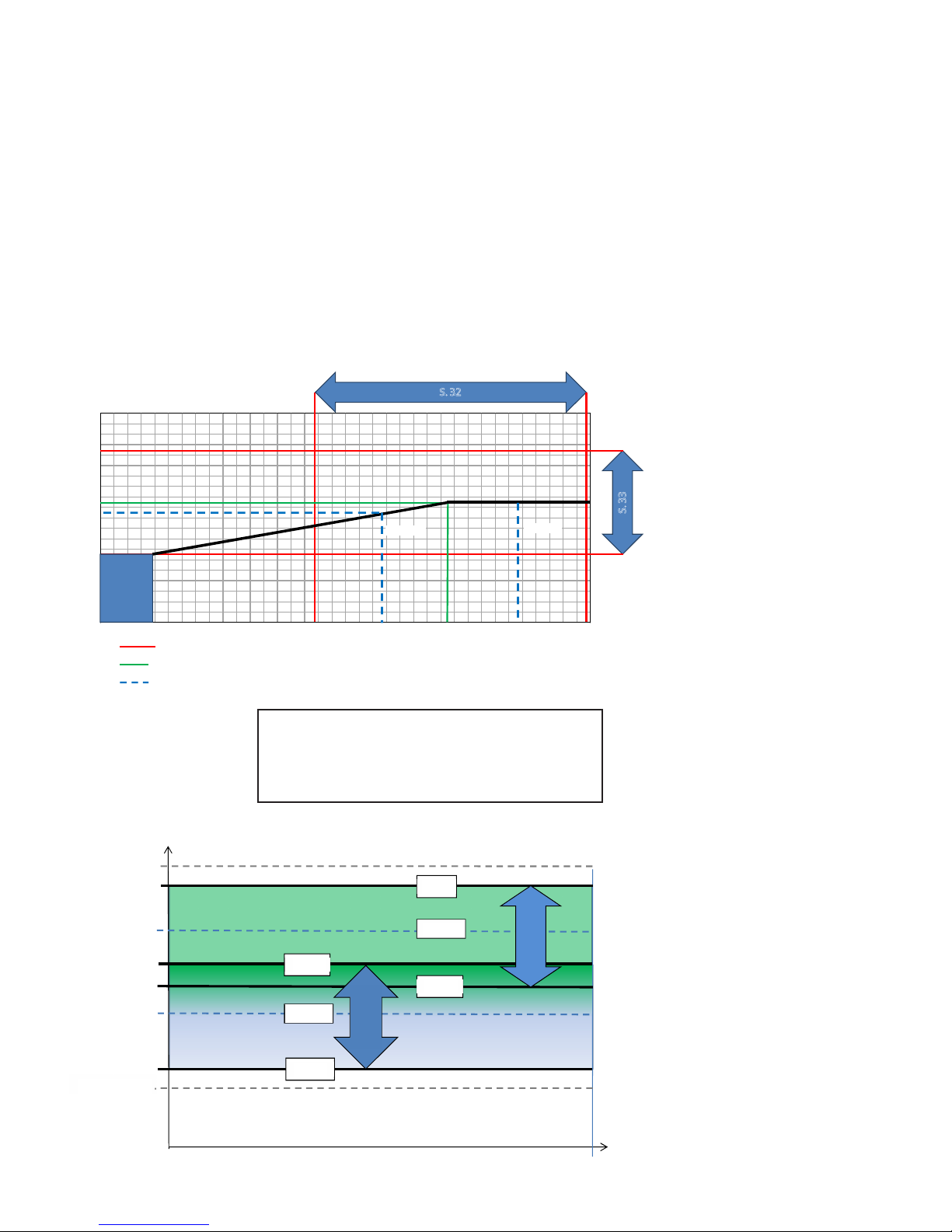
32 – Humidity max. temperature
Setting the end point for outside temperaturecompensation (T3), see the X-axis on the graph.
Setting option: 5-25°C.
33 – Humidity max. value
Setting the end point for outside temperature
compensation, see the Y-axis on the graph (desired max.
humidity value).
Setting option: 35-85%.
34 – Humidity fan speed
Setting of how much the fan speed may differ in relation to
the desired fan speed. See menu items 11, 12, 14 and 15.
Setting option: 5-30%.
Examples
Set point 34 = ± 15%
With a desired fan speed of 3, the fan speed will be able to
fluctuate by ± 15%. Since fan speed 3 is set at 75% in
Service Menu 12 and 15, the fan speed will be max. 90%
and min. 60%.
The same applies to fan speed 2. Since fan speed 2 is set at
50% in Service Menu 11 and 13, the fan speed will be max.
65% and min. 35%.
Fan speed is regulated by ±1% once every 10 min.
Setting option: See item 35
= Grænser
= Standardindstilling
= Eksempler
Eksempel 1
Ved en frisklufttemperatur på 10°C vil værdien for relativ
fugtighed være 55 %.
Eksempel 2
Ved en frisklufttemperatur på 20°C vil værdien for relativ
fugtighed være 60 %.
100%
95
90
85
80
75
70
65
60
55
50
45
40
35
30
25
20
15
10
5
0 - 10 -9 - 8 -7 -6 -5 - 4 -3 -2 - 1 0 1 2 3 4 5 6 7 8 9 10 11 12 13 14 15 16 17 18 19 20 21 22 23 24 25
S. 33
S. 32
Pre-
setting
Eks. 1
Eks. 2
RH
Fast
indstilling
Frisklufttemperatur
Trin 3 = 75 %
35 %
65 %
90 %
60 %
±15 %
±15 %
S.34
S.34
Trin 4 = 100 %
Trin 2 = 50 %
Trin 1 = 25 %
13
35 – Humidity regulating frequency
Setting of desired frequency for how often the fan speed
may be changed.
The function is defined as 1% per unit of time.
When humidity regulation is activated, the current
humidity is continuously measured via the integrated
humidity sensor in the ventilation unit, which is placed
in the extract air duct.
Setting option: 1-60 min.
Outside temperature compensation curve
Fan speed
Presetting
E.g., 1
90%
65%
60%
35%
±15%
±15%
= Boundaries
Outdoor air temperature
= Factory setting
= Examples
E.g., 2
Example 1
The RH value at an outdoor air temperature of 10°C is 55%.
Example 2
The RH value at an outdoor air temperature of 20°C is 60%.
RH
Level 4 = 100%
Level 3 = 75%
Level 2 = 50%
Level 1 = 25%

14
36 – Right/Left (only relevant for ECO 190)
NOTE: THIS FUNCTION SHOULD ONLY BE ADJUSTED BY
AN AUTHORISED VENTILATION CONTRACTOR.
ECO 190 is delivered by default in a right-configured
version. If the unit needs to switch to left-configured
design, reconfigure the temperature sensors for this by
setting this function to 1.
Note that you will continue to have to undertake hardware
changes, e.g. proper connection of condensation drain,
tipping of exchangers, moving of humidity sensor. Contact
Genvex if you need more detailed information.
37 – Preheat PI P
P-band for the PI controller for the electrical modulating
preheater.
The P-band controls the amplification of the controller
following a deviation from the set point (speeder)
38 – Preheat PI I
I-band for the PI controller for the electrical modulating
preheater.
The function controls how quickly the controller adapts
to a deviation of the set point (brake).
39 – Preheat Reg
The Preheat Cycle function works, as follows:
E.g. necessary output 50% and cycle = 60 sec means that
the controller will switch the preheater on for 30 sec and
off for 30 sec.
Note: Please refer to your country-specific regulations on
limitations when adjusting this function.
The modulating preheater function refers to the value
adjusted in set point no. 20.
The preheater will try to maintain a steady freish air
temperature according to this set point.
When the modulating preheater is used, the existing
outdoor air temperature sensor (T3), which is built into the
ventilation unit, can be used as reference. No extra
temperature sensor is required.
40 – Reheat offset
Offset for reheater with reference to the set point for the
requested temp on the display (user menu 01).
E.g. requested temp = 20°C
Offset value = 2 reheater aims to maintain a supply
temperature of 18°C
41 – Reheat PI P
P-band for the PI controller for the electrical modulating
reheater.
The P-band controls the amplification of the controller
following a deviation from the set point (speeder).
42 – Reheat PI I
I-band for the PI controller for the electrical modulating
preheater.
The function controls how quickly the controller adapts to a
deviation of the set point (brake).
43 – Reheat Reg
The Reheat Cycle function works, as follows: E.g. necessary
output 50% and cycle = 60 sec means that the controller
will switch the reheater on for 30 sec and off for 30 sec.
Note: Please refer to your country-specific regulations on
limitations when adjusting this function.
The modulating reheater function refers to the value
adjusted in set point no. 40.
The reheater will try to maintain a steady supply air
temperature according to this set point.
When using the modulating reheater, it will be necessary to
replace the inlet air temperature sensor (T1) in the
ventilation unit with a new temperature sensor installed
upstream of the reheater.
44 – Display Model
This is where you choose which external display is selected
together with the Optima 260 control system.
0 = No display
1 = OPT100 Design/OPT100 Opus
2 = Boost button
45 – Boost time 1 (only relevant if a boost button is purchased)
This is where you choose how many minutes of pressing the
boost button will lead to forced operation – when the
button is pressed once
46 – Boost time 2 (only relevant if a boost button is purchased)
This is where you choose how many minutes of pressing the
boost button will lead to forced operation – when the
button is pressed twice
47 – Boost time 3 (only relevant if a boost button is purchased)
This is where you choose how many minutes of pressing the
boost button will lead to forced operation – when the
button is pressed three times
48 – Calendar on/off
This is where you can activate calendar functions. See a
more detailed description under the item "calendar".
15
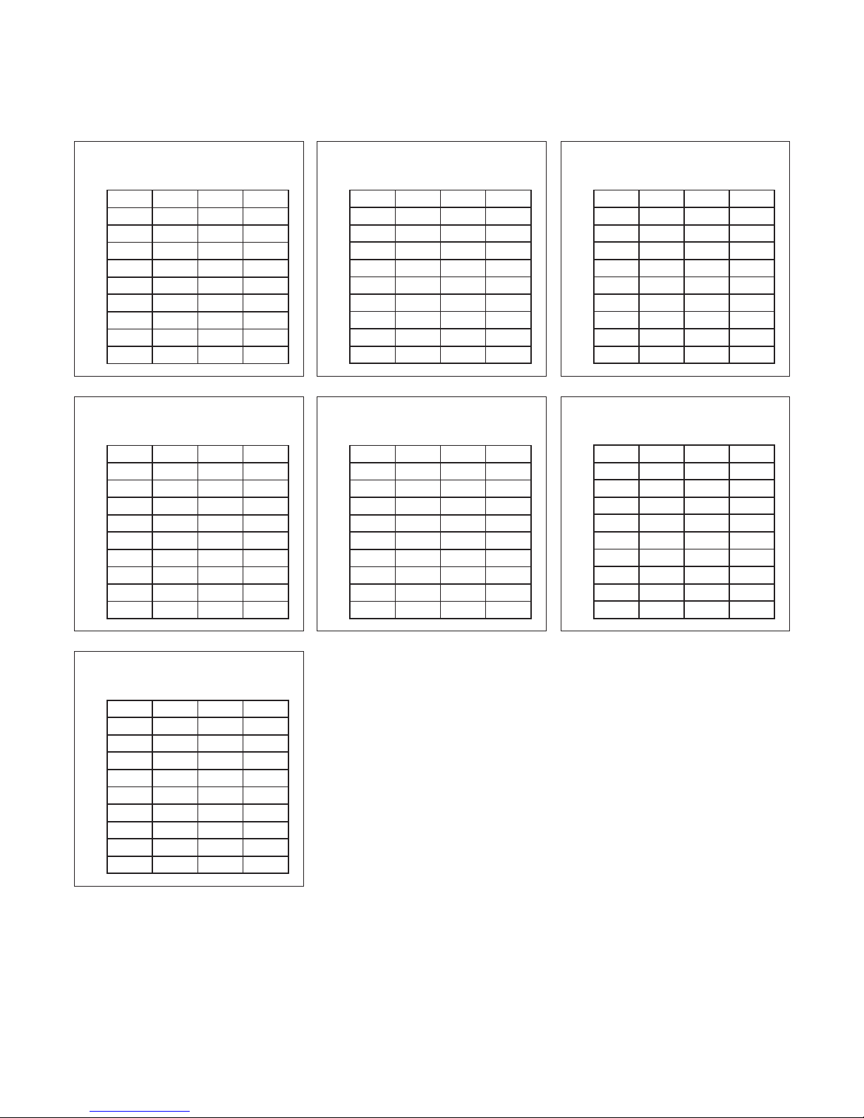
Schedule for week program
Red. T2 = Reduced room temperature (Night set-back)
Hours Minutes Speed Red. T2
1)
2)
3)
4)
5)
6)
7)
8)
9)
10)
Monday
Hours Minutes Speed Red. T2
1)
2)
3)
4)
5)
6)
7)
8)
9)
10)
Thursday
Hours Minutes Speed Red. T2
1)
2)
3)
4)
5)
6)
7)
8)
9)
10)
Sunday
Hours Minutes Speed Red. T2
1)
2)
3)
4)
5)
6)
7)
8)
9)
10)
Tuesday
Hours Minutes Speed Red. T2
1)
2)
3)
4)
5)
6)
7)
8)
9)
10)
Friday
Hours Minutes Speed Red. T2
1)
2)
3)
4)
5)
6)
7)
8)
9)
10)
Wednesday
Hours Minutes Speed Red. T2
1)
2)
3)
4)
5)
6)
7)
8)
9)
10)
Saturday

16
6.1 Regulation of Optima 260
Regulation of room temperature
There are 2 methods of regulation – see Service Menu item
19. If supply air regulation has been selected, the controller
will blow in air with the temperature set, provided that a
reheater is fitted to the system. The supply air temperature
is regulated by the supply air sensor, T1.
When using extract air temperature control, we recommend
that the supply air temperature be configured 2-3°C below
the room temperature.
Relay R8
When the system is running at levels 1, 2, 3 or 4, the relay
will be turned on. This function can be used to e.g. control
an optional fresh air damper or the discharge air damper.
6.2 Extra heating and cooling
Water reheating
For systems with water reheaters, the motor-operated
reheater will begin to regulate (PI regulation) when the
temperature has fallen 1°C below the set temperature.
Electrical reheating on/off version
For systems with electrical reheaters, the reheater will
connect when the temperature has fallen 1°C below the set
temperature. If the regulation time is set to, e.g. 3 minutes,
temperature sensor T1 will measure if the temperature is
now above or below the temperature set after 3 minutes.
If the temperature is still below the set temperature,
the reheating will keep running. When the temperature
reaches the set value, the electrical reheater will disconnect.
Electrical reheater (modulating)
As regards systems with a modulating electrical reheater,
the electrical reheater will automatically adapt to changes
in airflow and temperatures maintaining a constant
temperature according to the requested set point.
The controller will be adjusting the electrical output of the
reheater automatically.
Extra cooling
If an extra cooling device is fitted to the system, such a
device will turn on when the bypass motor is open
completely and turn off again when the bypass motor
begins to turn off again.
Systems with an electrical preheater will regulate in the
same way as an electrical reheater.
6. FUNCTION

17
Follow the following instructions to achieve optimal
performance:
Before you open the unit, turn off the power/
pull out the plug and wait until the fans have
stopped completely.
A couple of days after the primary installation, check that
the condensation outlet is working.
Environmental requirements
When repairing or dismantling the unit, statutory
environmental regulations must be observed regarding
recycling and destruction of various materials.
7.1 Unit
Filters
When the alarm flashes in the control panel display, the
filters must be changed. Stop the system using the circuit
breaker of the unit or the circuit breaker on the terminal
board. Open the front cover/filter drawers and remove the
filters. Once the filters are changed, reset the filter timer.
There is a danger of cuts from sharp edges.
The edges must not be damaged.
Vacuum cleaning or using pressurised air on the
filters is not recommended as it can impair filter
performance.
G4 = Standard filter
F5 = Fine filter
F7 = Pollen filter
Condensation drain:
When changing the filter in August/September, before the
outside temperature falls to 5°C, check that the
condensation drain is not blocked by dirt and make sure
that there is water in the water trap. Pour 1 litre of water
into the condensation tray and make sure that it runs off
freely. If the condensation drain does not work, this could
lead to water damage at your home.
Heat exchanger:
Inspect the heat exchanger every year. If it is dirty,
remove it and:
• Alu-exchanger: Wash in lukewarm soapy water and rinse
using a hand shower, if necessary.
• Plastic exchanger: No cleaning with solvents – use only
clean water and carefully remove dust from air intake
surfaces with a household vacuum cleaner.
Fans
Inspect the two fan wheels for dirt every year. If they are
dirty, they can be washed with a brush, bottle cleaner, etc.
Supply air and extract air valves
Clean the valves by wiping them with a dry cloth.
Make sure that the valves do not turn causing changes to
the air volume.
7.2 Alarms
Filter timer
The control has a filter timer to guarantee that the filter is
changed and that optimal operation is achieved. When the
timer reaches the set value, a key will flash in the display
until the filters have been changed.
Once the filters are changed, press and hold down the filter
indicator key until the diode switches off.
7.3 Dismantling/taking the system out of service
Do as follows:
Disconnect the power supply, i.e. the power cables.
Disconnect the condensation outlet and power cables for
any reheaters/preheaters. Disconnect the cables to the
control panel and dismantle ducts.
If the system should be taken out of service, the ducts must
be dismantled to avoid condensed water in the system and
in the ducts. Close all supply air and extract air valves.
7. MAINTENANCE

18
8.1 Safety thermostat in electrical heater
(optional equipment)
If an electrical heater suffers from a fault, the safety
thermostat will disconnect. The heater is equipped with a
fire thermostat that automatically cuts off the power
supply if the temperature exceeds 50°C. If the temperature
falls, the heater automatically re-engages.
As an additional safety measure, there is a built-in thermal
cut-out, which disengages if the temperature exceeds 100°C.
Re-engaging must be done manually.
This does not apply to PTC electrical heaters.
8.2 The system is not running
Unit stopped:
Possible error:
• Fuse in main board has blown, no power to unit
• One of the fuses on the circuit board of the unit has blown
• Loose wire, no power to unit
• Loose wire between unit and control panel
• Faulty or incorrectly set week program
• Filter timer has switched the system off
Condensed water is leaking from the unit
Possible error:
• Condensation outlet blocked by dirt
• The condensation outlet is not adequately protected
against freezing at low outdoor temperatures.
8.3 Air faults
No supply air:
Possible error:
• Faulty supply air fan
• Clogged supply air filter
• Clogged outdoor air grill due to dirt and leaves during the
fall and snow and ice during the winter.
• Fuse on the circuit board has blown
• The unit is in defrost mode (supply air fan stops)
• Incorrect value set in User Menu item 2
No extract air:
Possible error:
• Faulty extract air fan
• Clogged extract air filter
• Fuse on the circuit board has blown
8. TROUBLESHOOTING
Cold supply air:
Possible error:
• Clogged heat exchanger
• Faulty extract air fan
• Clogged extract air filter
• The electrical reheater is disconnected from the
overheating thermostat (only units with electrical
reheater installed).
• Air in the heating pipes, faulty thermostat/motor valve,
incorrect setting of control panel

19
8. TABLE OF FACTORY SETTINGS
Item Headline Factory setting Configuration area Date Date Date Date
(5.5) 01 Temperature 21°C 10 - 30°C
02 Preheating OFF ON/OFF
03 Reheating OFF ON/OFF
04 Timer levels 3 and 4 OFF ON/OFF
05 Change filter 3 months 1 - 12 months
06 Humidity control OFF ON/OFF
(5.8) 10 Level 1 Supply air 30% 0 - 100%
11 Level 2 Supply air 50% 0 - 100%
12 Level 3 and 4 Supply air 75% 0 - 100%
13 Level 1 Extract air 30% 0 - 100%
14 Level 2 Extract air 50% 0 - 100%
15 Level 3 and 4 Extract air 75% 0 - 100%
16 Not applicable OFF ÷ 5 - 0°C
17 Timer levels 3 and 4 3 hours 1 - 9 hours
18 Filter/stop OFF ON/OFF
19 Method of regulation 2 0 - 2
20 Preheating ÷ 3°C ÷ 15 - 0°C
21 Bypass open 3°C 1 - 10°C
22 Regulation water 20 sec. 1 - 250 sec.
23 Regulation electricity 3 min. 1 - 30 min.
24 Frost reduction 0°C 0 - 10°C
25 Frost protection OFF ON/OFF
26 Frost protection temperature 5°C 0 - 10°C
27 Help functions 0 0 - 5
28 System stop OFF ON/OFF
29 Turn off bypass 4°C 0 - 20°C
30 Modbus Mode 2 0 - 2
31 Modbus Address 1 1 - 247
32 Humidity max. temperature 15°C 5 - 25°C
33 Humidity max. value 60% 35 - 85%
34 Humidity fan speed 15% 5 - 30%
35 Humidity regulating frequency 10 min. 1 - 60 min.
36 Right/Left 0 0-1
37 Preheat PI P 5 1-255
38 Preheat PI I 200 1-255
39 Preheat Reg 40 10-120
40 Reheat offset -2 0-20
41 Reheat PI P 5 1-255
42 Reheat PI I 200 1-255
43 Reheat Reg 40 10-120
44 Display Model 1 0-2
45 Boost time 1 (min) 15 0-250
46 Boost time 2 (min) 30 0-250
47 Boost time 3 (min) 60 0-250
48 Calendar on/off 0 0-1

THE ORIGINAL BREATH OF FRESH AIR
08:116-1702
Genvex – the Original Danish Ventilation System
Genvex is a genuine Danish original. We invented our ventilation system
more than 40 years ago, and we are still ahead of the pack when it comes
to development and production of the strongest and most durable
ventilation systems on the market.
Our units are installed in thousands of Danish homes and deliver fresh,
clean air, which is completely free from pollen, dust and harmful
particles. This helps extend the service life of the house and creates a
healthy and pleasant indoor climate for thousands of people. At the same
time, our system is an important element when it comes to saving energy
at home and in society as a whole – a Genvex system actually allows you
to recover up to 95% of the heat energy.
All
Genvex systems
have energy label
A
An original Genvex system is built
by skilled, experienced technicians
and has a service life that in many
cases is measured in decades.
Our units are approved according to
all applicable standards and are also
easy to operate and service on a
daily basis. Last, but not least, all
Genvex systems are produced with
a focus on compact installation
dimensions and ease of installation
and can be installed discreetly and
beautifully in all types of homes.
We are part of the NIBE Group – a
family of companies specialised in
delivering hot water, heating and
home comfort to homeowners all
over the world.
A list of our dealers is available at www.genvex.dk
KVM-Genvex A/S • Sverigesvej 6 • DK-6100 Haderslev • Tel.: +45 73 53 27 00 • salg@genvex.dk • genvex.dk
 Loading...