


Thank you for purchasing the Buddy Kick from Genuine Scooter Company. The efficiency and
longevity of each scooter will depend heavily on the operating method of each user. This
owner's manual will provide you with operating instructions, precautions and general
maintenance information required to safely operate and maintain your scooter.
Please read the entire manual before operating your scooter. This manual should stay with
the vehicle at all times and should transfer to the new owner if the vehicle is sold.
If you have any questions, please ask your authorized Genuine dealer for assistance.
WARNING: California Proposition 65
Operating, servicing, and maintaining a passenger vehicle or off-road vehicle can expose you to chemicals including
engine exhaust, carbon monoxide, phthalates, and lead, which are known to the State of California to cause cancer,
birth defects, and other reproductive harm. To minimize exposure, avoid breathing exhaust, do not idle the engine
unless necessary, service your vehicle in a well-ventilated area, and wear gloves or wash your hands frequently when
servicing your vehicle. For more information, visit www.P65Warnings.ca.gov/passenger-vehicle.
1

CONTENTS
WARRANTY INFORMATION.......................................................................................................................................................................4
MOTORCYCLE NOISE REGULATION.......................................................................................................................................................5
1. SAFE DRIVING .......................................................................................................................................................................................... 6
2. VEHICLE LAYOUT ......................................................................................................................................................................................7
3. VEHICLE IDENTIFICATION....................................................................................................................................................................8
4. CONTROL FUNCTIONS.......................................................................................................................................................................... 9
4-1. MAIN SWITCH (FOR IGNITION & ILLUMINATION) ....................................................................................................... 9
4-
2 FUEL CAP ....................................................................................................................................................................................... 9
4-3 LOCK FOR STEERING HANDLEBAR ................................................................................................................................... 10
4-
4 SEAT LOCK .................................................................................................................................................................................. 10
4-5 LUGGAGE CABINET ................................................................................................................................................................ 10
6 HANDLEBAR SWITCHES ....................................................................................................................................................... 11
4-
4-7 FRONT (REAR) BRAKE LEVERS ............................................................................................................................................. 12
4-8 POWER-FAILURE SWITCH .................................................................................................................................................... 12
4-9 POWER DISCONNECTION SWITCH .................................................................................................................................. 13
5. DIGITAL DISPLAY OPERATION.....................................................................................................................................................14-19
6. PRE-USE VEHICLE INSPECTION...................................................................................................................................................... 20
6-1. BRAKE ......................................................................................................................................................................................... 21
6-2 THROTTLE .................................................................................................................................................................................. 21
6-3 ENGINE OIL ............................................................................................................................................................................... 21
6-4 TIRE ............................................................................................................................................................................................... 22
6-5 HEADLIGHT & TURN SIGNAL LIGHT ................................................................................................................................. 22
6-6 FUEL TANK ................................................................................................................................................................................. 23
2

6-7 EXHAUST SYSTEM.................................................................................................................................................................... 23
7. ESSENTIALS FOR USE AND DRIVING .............................................................................................................................................. 24
7-1 START-UP OF THE ENGINE ................................................................................................................................................... 24
7-2 PASSENGERS PEDAL................................................................................................................................................................ 24
7-3 WARM-UP ................................................................................................................................................................................... 24
7-4 DRIVING ...................................................................................................................................................................................... 25
7-5 ACCELERATION ......................................................................................................................................................................... 25
7-6 USE OF BRAKES ......................................................................................................................................................................... 25
7-7 BREAKING-IN OF ENGINE .................................................................................................................................................... 25
7-8 PARKING ..................................................................................................................................................................................... 26
8. CHECK AND ADJUSTMENT ................................................................................................................................................................ 27
8-1 BRAKE ......................................................................................................................................................................................... 27
8-
2 SUSPENSION ............................................................................................................................................................................ 28
8-3 REPLACEMENT OF FUSES .................................................................................................................................................... 29
8-4 BATTERY ..................................................................................................................................................................................... 29
9. PERIODIC MAINTENANCE AND EASY REPARATION ............................................................................................................... 30
9-1 PERIODIC MAINTENANCE SCHEDULE ............................................................................................................................ 31
9-2 PERIODIC MAINTENANCE SCHEDULE FOR EXHAUST CONTROL ........................................................................ 32
9-3 NON-PERIODIC MAINTENANCE SCHEDULE FOR EXHAUST CONTROL .............................................................32
9-4 CLEANING OF AIR FILTER ...................................................................................................................................................... 33
9-5 CHECK OF SPARK PLUG ......................................................................................................................................................... 33
9-6 REPLACEMNET OF GEAR OIL ............................................................................................................................................... 34
9-7 REPLACEMNET OF ENGINE OIL .......................................................................................................................................... 34
SPECIFICATIONS ....................................................................................................................................................................................... 35
REPORTING SAFETY DEFECTS..................................................................................................................................................................36
PERIODIC MAINTENANCE RECORD ............................................................................................................................................37-38
3

WARRANTY INFORMATION
Your vehicle is covered by a Manufacturer's Limited Warranty and an EPA Emissions Related
Components Warranty.
If you purchased your vehicle in the state of California, you are also covered by a California Emission
Control System Warranty.
Detailed warranty information can be found in your warranty booklet provided separately from this
manual.
To maintain your warranty coverage and to provide maximum safety and enjoyment from your
Genuine Scooter, use only Genuine approved parts, accessories, and lubricants.
Genuine OEM Parts - Genuine brand replacement parts are the exact parts that were originally
installed on your vehicle. Genuine parts will provide you the maximum performance and longevity
giving you confidence and satisfaction that your vehicle is operating as it was designed.
Genuine Approved Accessories - The addition of unsuitable accessories can result in unsafe operating
conditions. Genuine approved accessories have been designed for and approved by Genuine for use
on your scooter. Always install Genuine approved accessories on your scooter.
Installing unauthorized parts on your vehicle may void your warranty and may make your vehicle
unsafe to drive. Your Genuine dealer can assist you in selecting and correctly installing accessories
for your scooter.
4

Motorcycle Noise Regulation
TAMPERING WITH NOISE CONTROL SYSTEM PROHIBITED
Federal law prohibits the following acts or the causing thereof:
(1) The removal or rendering inoperative by any person other than for purposes of maintenance, repair ,
or replacement of any device or element of design incorporated into any new vehicle for the purpose of
noise control prior to its sale or delivery to the ultimate purchaser or while it is in use or
(2) the use of the vehicle after such device or element of design has been removed or rendered
inoperative by any person.
"AMONG THOSE ACTS PRESUMED TO CONSTITUTE TAMPERING ARE THE ACTS LISTED BELOW".
These acts include tampering with the following systems; i.e., modification, removal, etc.
Exhaust System - Muffler, Exhaust pipe, Silencer
Intake System - Air cleaner case, Air filter, Intake duct
5

1. SAFE DRIVING
Please allow significant time to complete any
action shown as follows.
Attention: Please activate turn signal lights to notify other
vehicles in front of you and behind you that your vehicle is
turning.
Do not abruptly stop the vehicle when driving on a
1.
wet roadway in order to avoid a crash. Please
carefully and slowly apply the brakes on wet roadways.
2. Please slow down the vehicle prior to arriving at a
corner or a crossroad; accelerate the vehicle slowly
after the vehicle has made a turn.
4. Please slow down and carefully pass when riding over a
wet steel plate used during road construction or a
manhole cover; keep your vehicle in a vertical position
while driving over the wet steel surface.
5. Prior to driving, check the brake surfaces, which
may be wet from cleaning the vehicle.
6. The driver shall wear a safety helmet, gloves,
protective trousers (with bottoms of the trouser legs
around ankles fastened) and a brightly colored jacket.
7. Do not carry excessive luggage on the vehicle as
this may destabilize the vehicle. All luggage shall
be secured appropriately; Loose luggage might
adversely affect the stability or distract the driver
potentially causing an accident.
8. It is not necessary to warm up the vehicle before
riding; This vehicle is equipped with fuel injection and
the improved technology will protect the engine and
the environment during warm-up. Although it is not
necessary to warm up the vehicle, do not drive with
rapid acceleration or immediately accelerate to
maximum high-speed until the engine has warmed up
completely.
3. Please carefully drive the vehicle when passing
other vehicles parked on the roadside in order to
avoid any incident such as a car door suddenly
opening or a passenger emerging from inside the
vehicle.
6

2. Vehicle Layout
Front Brake Shaft
Throttle Exhaust
Rear Fender
Rear Brake Lever
Headlight
Turn Signal Light
(Front)
Front Fender
Front Fork Side Stand
•
The components mentioned above are representative parts only. Please refer to the actual vehicle
Footrest
Center
Stand
Mirror
Seat
Grab Rail
Tail
Light
for detailed components.
7
Speedometer
Turn Signal Light (Rear)
Rear Shock

3. VEHICLE IDENTIFICATION
3-1 VEHICLE IDENTIFICATION NUMBER
Each vehicle manufactured by Genuine Scooter
Company has been marked with a vehicle
identification number whose position is shown as
follows:
1. Central position below the front luggage
2. Steel frame in the middle section
(17 alphanumeric codes found with the
cover on the vehicle identification number
removed)
8

4. CONTROL FUNCTIONS
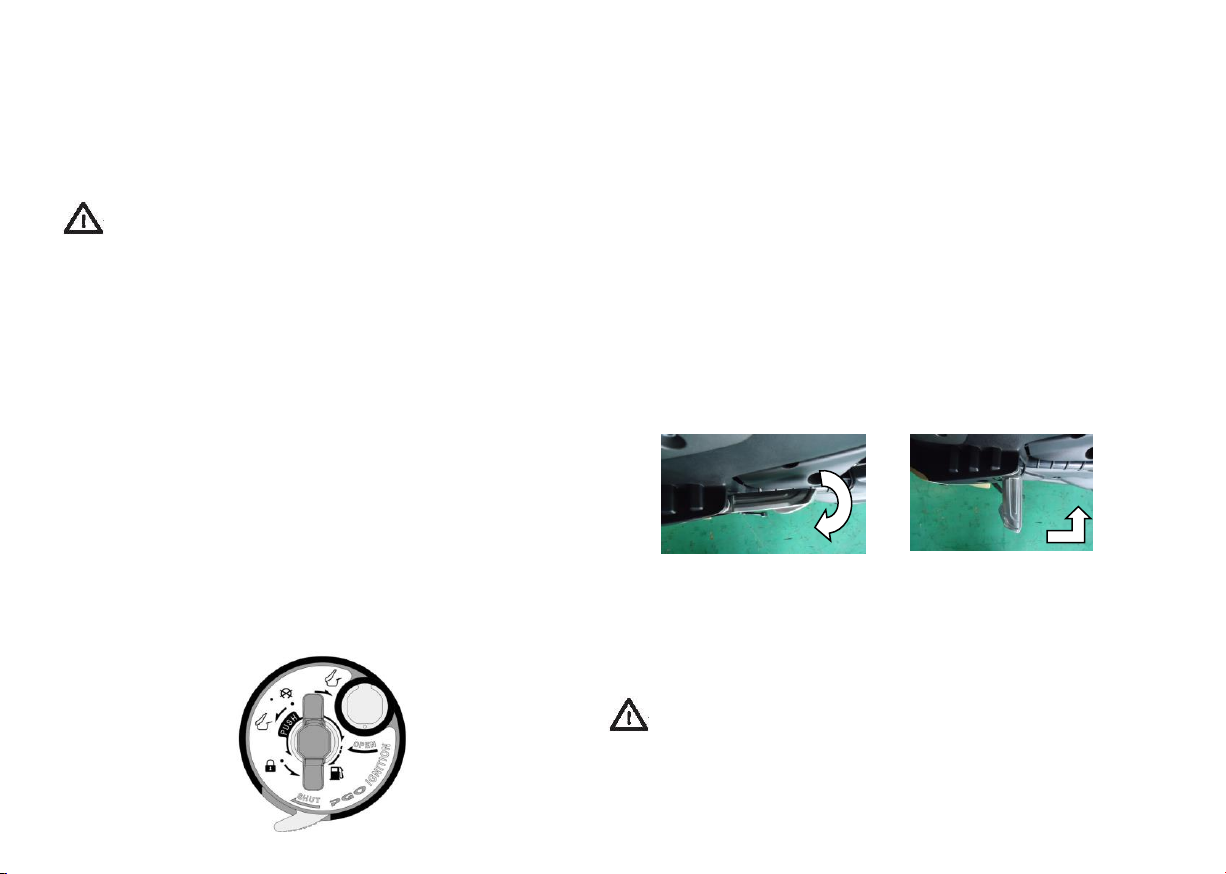
4-1. MAIN SWITCH (FOR IGNITION & ILLUMINATION)
The instructions of the ignition switch used to control
ignition and illumination are shown as follows:
1. Power is disconnected; key removable
2. Power connected; engine ready to be started;
do not remove key
3. Handlebar locked; power disconnected; key
removable. Please refer to "Steering
Handlebar" (P-12) for correct operations.
4. "PUSH" and turn counter-clockwise: Open
seat with the key location at "A", "B", or "C".
5. "B": Press and turn the key clockwise to open
fuel cap .
6. Remove the key and press the "E" tab
rightward to protect the key hole from
foreign objects and to activate the anti-theft
status.
7. Plug the shutter magnetic lock on the key
shank into "F" and turn it rightward to open
the cover.
Attention: Turn the key to "OFF" or "LOCK” and remove
it when the motorcycle is not driven.
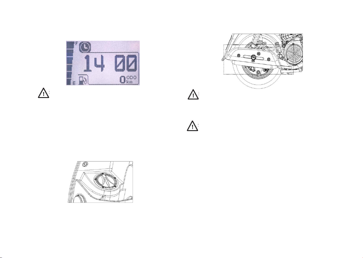
4-2 FUEL CAP
1. With the key located at , press "PUSH"
and turn the key clockwise to open the fuel cap.
2. Press the fuel cap frontward and downward to
close the fuel cap.
9

4-3 LOCK FOR STEERING HANDLEBAR
Turn the steering handlebar to the far left prior to
locking it. Turn the key to “LOCK” from “OFF”
and remove key. Turn the key clockwise to unlock
the steering handlebar.
4-5 LUGGAGE CABINET
The luggage compartment is located under the seat.
Please put your helmet straight inside the luggage
compartment and store the helmet facing toward the rear
of the vehicle.
4-4 SEAT LOCK
1. Push and turn the key counterclockwise, which is
at any position, in order to lift and open the seat.
2. Please properly use the seat lock to protect any
objects inside the luggage compartment and
activate the anti-theft function prior to leaving your
vehicle.
3. Please lay down and press the seat gently in order
to activate the seat lock and extend its service life.
10
Attention: Ensure personal articles stored inside the
luggage compartment do not exceed the maximum
load. Maximum load: 12 lbs
Directions for use of the luggage compartment:
Do not store any object that is not heat-resistant
1.
or inflammable inside the luggage compartment
because the luggage compartment can become
heated from the sun or the engine running.
2. Do not store any precious or fragile objects inside
he luggage compartment.
Cover objects stored inside the luggage compartment
3.
with waterproof material due to possible intrusion
of moisture from rain or during cleaning of the
vehicle.
Attention: Please properly close the seat prior to
leaving the vehicle.

4-6 Handlebar Switches
1. High / Low beam
PASS Light: Press "PASS" and activate the headlight to
2.
notify fellow motorists of your intent to pass.
Turn signal light: Press to the left to signal a left hand
3.
turn, press to the right to signal a right hand turn.
Press the center to turn off signal lights.
Horn
4.
1
2
3
4
Kill Switch: When switch is in the "Kill" position,
5.
the engine will not run. When the switch is in the
"Run" position, the engine can be operated.
Attention:
The kill switch is for stopping the engine in
emergency situations only.
Leave the kill switch in the run postion and stop
the engine with the key switch during regular use.
Leaving the kill switch in the "Kill" position with
the main key switch on will rapidly deplete the
battery. The lights, dash and fuel pump all are
engergized in this configuration.
5
6
6.
Start: Pull in the brake lever (front or rear)
and press "Start" button simultaneously to start up
the engine.
11

4-7 Front (Rear) Brake Lever
Rear Brake Lever
Left Lever: Rear brake. Grip the brake shaft
backward to activate the rear brake.
Front Brake Lever
Right Lever: Front Brake. Grip the brake shaft
backward to activate the front brake.
4-8 Power "Anti-theft" Switch
Function: Prevent theft from hot wiring
ignition
Use:
1. Keep the "Power Failure Switch" at "O" to disable
start-up after the vehicle is parked.
"O": Start-up disabled; "-": Start-up enabled
2. "Power Failure Switch" at "O": "EMS---" and
indicated on the display panel; "Power Failure
Switch" at "-": "EMS OK" only (no other icons)
indicated on display panel.
Attention: Do not change the switch's position
while the engine is still running. Change
position only when the vehicle is parked.
12

Attention:
The charging outlet is available when the power
1.
switch is on. DO NOT charge devices during
engine start-up.
2.
Only replace the (1A) fuse for
outlet when the charging socket is empty and all
devices unplugged.
3. Unplug all devices prior to engine start-up in
order to protect your device from damage.
4.
Bring the vehicle to your authorized Genuine
dealerto check in the event the voltage is greater
than 15V indicated on the display panel. Do not
use the outlet if voltage is over 15V.
the power supply
4-9 Power Disconnection Rollover Switch
Your vehicle has a rollover switch which will kill the
engine in the event your vehicle falls over while running.
It is necessary to disconnect and reconnect the battery
following a rollover to reset your vehicle to operation.
Attention:
- Some error messages (Code: P0261) will be indicated on
the display panel when the rollover switch
activated. These messages are not harmful to the vehicle.
- Bring the crashed vehicle to your authorized Genuine
dealer for further inspection.
has been
13

5. SPEEDOMETER FUNCTIONS
5-1-a. INDICATION OF SPEEDOMETER
Miles per hour
Functional icon
Engine oil
indicator
High beam indicator
Turn signal light (left)
Fuel level
Function key
Information
for functions
EMS indicator
Low beam indicator
Turn signal light (right)
Mileage information
14

█ EMS Information
█ Millage Information
Engine Management System
•
(EMS) diagnosis function
automatically activated when
power connected.
• Any error will be indicated on
the display panel.
• The millage information is
always indicated at the
bottom for any mode.
• Press and hold the button
to switch between“km” or
“mile” in the
odometer“ODO” mode.
• Changing between ODO
and TRIP: Continuously
press the button on the
display panel to switch
ODO or TRIP.
• Press the button to reset
the mileage on the display
panel in "TRIP” mode.
█ Time Information
█ Voltage Information
█ RPM
█ Fuel Level
• Press the button on the
display panel to indicate
“Time”.
• Refer to “Set-Up” for
adjustment of “Time”.
• Press the button on the
display panel to indicate
“Voltage”.
• Voltage alarm: Battery voltage
lower than 11.5V or greater
than 15.5V
• Press the button on the
display panel to indicate
“RPM”.
• “Fuel Level” is always
indicated at the left-hand
side of the display panel for
any mode.
• Low fuel level: “Fuel
Level” blinking and a symbol
for low level indicated on the
upper right corner in case of
one scale only.
15

Set-Up Mode
With the key in the "off" position, press and hold the button.
•
Turn key to the "on" position, continuing to hold the button.
•
•
Once the electonic dash has fully powered up, you will have entered the page for set-up.
Time Set
•
Short press to adjust time for each digit.
•
Long press to
Long press to set time and switch to contrast.
•
Display Contrast
•
Short press to adjust contrast.
•
Long press will set contrast and exit setup mode returning to normal display mode.
switch between “HR” and “MIN".
16

Standard Mode
Odometer: kilometers and miles
•
Short press to scroll through menus until "ODO" is displayed in bottom right corner.
•
Scroll to the tachometer page.
•
Long press will change between kilometers and miles
Trip Odometer
Short press to scroll through menus until "TRIP" is displayed in bottom right corner.
•
•
Scroll to the tachometer page.
•
Long press will reset trip odometer
17

Diagnostics
Short press to scroll through menus until you arrive at the diagnostic page.
•
•
Long press will enter diagnostic pages.
•
Any stored trouble codes will be displayed on page D-1
•
Short press advances to page D-2 showing System Information.
Short press advances to page D-3 showing real-time sensor
•
information: EG Speed: Engine speed (RPM)
TW: Engine Temperature (Celcius)
MAP: Manifold Air Pressure (kilopascals)
TPS: Throttle Position (% open) Note: Range is 0-60%
ISC: Idle Speed Controller (Position#)
18
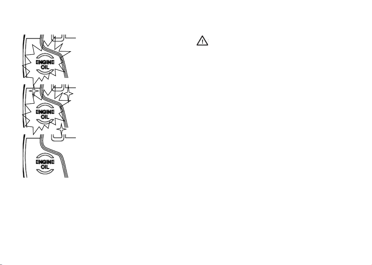
█ Reset of Oil Indicator
• The oil indicator“ON”
indicates the engine oil
should be replaced. Bring
your vehicle to a Genuine
dealer for oil change
service.
Attention: Please drive your vehicle to your
authorized Genuine dealer for inspection in the event
any EMS error
while riding. Attention: Do not change any of
the speedometer's functions while riding, for the
purpose of safety.
messages appear on the display panel
• Reset
the oil indicator
when service is completed.
• Press and hold the
button under ODO (total
mileage) for 3 seconds
until the oil indicator
blinks.
• When the oil indicator is
blinking, press and hold
the button for another 5
seconds in order to stop
blinking.
19

6. PRE-USE VEHICLE INSPECTION
-
Item Procedure Page
※Front Brake
※Rear Brake
Throttle Check the throttle function. Add lubricant and adjust the throttle, if necessary.
Engine Oil Check the lubricant level or add any lubricant as necessary.
Tire Check tire air pressure, wear and inspect for damage. 22
Switches / Speedometer
Center Stand Check function; add lubricant or adjust the center stand, if necessary.
Assembled Parts / Fasteners Check all assembled parts and fasteners; fasten or adjust, if necessary.
Fuel Tank Check the fuel level; add fuel as required.
Headlight & Turn signal light Check function.
Brake Shaft Check functions; add any lubricant, if necessary. 11;17
Note: Conduct the pre-use check before each ride. This check can be finished in a short period and will substantially
enhance safety. In the event any item failed or any component is not functioning properly, please check it immediately
prior to the next ride.
Check brake function, free play, brake fluid level and inspect for line damage or
leakage. If necessary, fill the brake fluid reservoir with FMVSS DOT4 brake fluid.
Check brake function, free play, brake fluid level and inspect for line damage or
fluid leakage. If necessary, fill the brake oil tank with FMVSS DOT4 brake fluid.
Check functions. 12
12;21;23
12;21;23
21
21
26
23
18
20

6-1. Brake
(Refer to P-23 for details.)
1. Brake Levers
Check free play of the front and rear brake levers;
make sure you are aware of their functions. Check the
brakes of the vehicle at the beginning of each ride
while driving at a low speed. Please correct any
improper free play.
Attention: A brake lever that is not firm when engaged
implies there is a problem with the brake system. Do not
drive your vehicle until the problem has been fixed. Bring
the vehicle to your authorized Genuine dealer for repair. A
loose brake lever is an indication there is a problem in the
brake system.
2. Brake fluid (Disk brake)
Check the brake oil level; add brake fluid if
necessary. Brake fluid designated: FMVSS DOT4
3. Leakage of Brake Fluid
Check all joints along the brake hose for any brake fluid
leaking from the joint or the brake cylinder. Leakage has
occured if you see wet or oxidized fluid sludge.
4. Check of Disc Brake (P-23)
Note: Please contact your authorized Genuine dealer to
repair disc brakes.
Attention: Please contact your authorized Genuine
dealer to repair leakage of brake fluid, if any. The leakage
implies potential risk in the brake system.
6-2 Throttle
Turn the throttle to check proper function and free play. Make
sure when you release the throttle it turns to its original
position automatically. If necessary, the throttle should be
adjusted by your authorized Genuine dealer.
6-3 ENGINE OIL
Attention: Check the engine oil level when parked and
on a flat surface.
Allow the engine to run 2-3 minutes first; then check
the engine oil level after the engine has been stopped
for 2-3 minutes.
Total volume: 1000 c.c
Oil to be replaced: 800 c.c
Engine Oil 10w40
Remove the dipstick and check the engine oil level. Add
engine oil as specified by your authorized Genuine
dealer to the upper limit in the event the oil level is
under the lower limit.
21

6-4 TIRE
Please check the following conditions in order to
ensure maximum performance, service life and safety.
1. Tire Pressure: Check the tire pressure prior to riding
the vehicle. Increase the tire pressure for any heavy
object loaded, as needed.
Normal tire pressure Front tire: 28 psi
Rear tire: 28 psi
2. Check
Check the tire condition prior to riding. If your
find there is damage to your tires, such as, wear,
cracks, nail, etc. , contact your authorized Genuine
dealer for service to repair or replace the damaged
tires, if necessary.
3. Check tread pattern (depths):
If the vehicle's tire tread depths are too shallow
as indicated by the tread wear indicators, contact
your authorized Genuine dealer for replacement.
Minimum depth of tread patterns (front and rear) =
0.8mm
Attention:
1. It is very dangerous to drive a vehicle with tire
treads that are excessively worn. In the event
the tire tread wear indicators display a worn tire,
please contact your authorized Genuine dealer
for replacement.
2. If a driver drives a vehicle with worn tire treads, it is normal
to feel a slight vibration in the handlebars.
6-5 Headlight and Turn Signal Light
1. Check that the headlights, turn signal lights, rear lights, brake
lights, and display panel lights and indicators are functioning
properly.
2. Switch
Check that the switches for the headlights, turn signal lights,
brake light, horn and start-up are all functioning properly.
Headlight
Turn Signal
Light (Front)
Turn Signal
Light (Rear)
Brake Light
Attention: Do not touch the surface of the
headlights after long periods of illumination due
to high temperature.
22
6-6 FUEL TANK
Attention
Do not spill gasoline or allow fuel to touch
1.
the high-temperature engine. The level of fuel
added into the fuel tank should be lower than
the fuel filling nozzle, or the gasoline will spill
as it heats and expands.
2. Do not allow spilled fuel to touch the exhaust
because the high temperature on the surface of
the exhaust can result in combustion of the
spilled fuel.
6-7 Exhaust System
A catalytic converter is installed in the exhaust pipe. The
purpose of the catalytic converter is to reduce pollutants in
exhaust gas. Do not alter the exhaust system.
Attention: To avoid burning, please park the vehicle in
a location where pedestrians or children cannot come into
contact with the high temperature exhaust.
Attention: Please adhere to the following instructions
in order to avoid damage to the catalytic converter and
other dangers.
Add premium unleaded gasoline only (91 octane or
1.
higher)
2. Do not drive, idle, or park the vehicle on flammable material.
3. Maintain the engine's peak running status. (Imperfect
systems such as engine circuit, ignition or fuel might
cause high temperatures at the catalytic converter.)
4. Perform periodic maintenance and inspection of the
vehicle in order to ensure good performance of the
entire exhaust control system.
23
7. ESSENTIALS FOR USE AND DRIVING
Drivers must be familiar with all skills necessary
to drive and control the vehicle and all vehicle
functions. For any questions, please contact
your authorized Genuine dealer.
Attention:
1. Do not start the engine in a poorly ventilated
place. The toxic fumes discharged from the vehicle
might make you lose consciousness or be killed in a
short period. Always operate the vehicle in a wellventilated area.
2. Make sure the side stand is properly retracted
prior to riding. If your side stand is down on the
vehicle while riding, this can cause serious
accidents.
7-1 Engine Start-up
1. Turn the main switch clockwise to engage power
supply.
2. Close the throttle; hold the front (or rear) brake
lever and press the start button to start the
engine.
3. The throttle can be slightly advanced to easily
start the engine at low temperatures (<0 Celsius) or
high altitudes (>6500 ft).
Note: If the engine does not start, release the start
button and try again after a few seconds. Engine
start-up should be completed within 5 seconds to
avoid excessive battery discharge.
7-2 Passenger Foot Pedals
When you want to use the passenger pedals, press
the pedal so that it pops out. When not in use,
press the pedal again to return to its original
position.
Attention:
1. Do not open the pedal when there is no passenger
onboard to avoid accidents.
2. The pedal is a footrest for the passenger only. Do
not use the pedal when there is no passenger onboard.
7-3 Warm-up
It is not recommended to warm up the vehicle at rest,
to reduce exhaust and pollutants. However, the
sudden acceleration of the vehicle at cold-start status
should be avoided for engine longevity.
Attention: Please refer to "Breaking-in of Engine"
prior to the first drive of the vehicle.
24
7-4 Driving
1. Hold the vehicle's handlebar; push the vehicle forward
and retract the center stand from the ground.
2. Straddle the vehicle and check the angles of the mirrors.
3. Carefully observe the traffic in front; activate the turn
signals prior to driving the vehicle on the road.
4. Slowly turn the throttle (right) and turn off the turn signal
7-5 Acceleration
Adjust the vehicle speed by turning the throttle. Turn the
throttle backward for acceleration and turn the throttle
forward for deceleration.
7-7 Running-In of the Engine
The run-in stage is critical to your vehicle's service life. As a
result, the following information must be read carefully. It is
recommended that vehicle loading should be limited during
the break-in period due to all of the new components
installed in the engine. The key point during the run-in stage
is breaking-in the components of the engine in order to
establish the best running conditions. Drivers should avoid
long-term operation at full throttle or any situation that
causes the engine to bear a heavy load.
Attention: If you experience any engine problems during the
running-in period, contact your authorized Genuine dealer.
7-6 Use of Brakes
Attention
1. Do not stop the vehicle suddenly or abruptly to avoid
sliding or rollover.
2. It is recommended to apply the front and rear brakes
simultaneously for best brake results and safety.
3. Carefully apply the brakes when the vehicle deviates
from normal direction. Stopping the vehicle improperly can
result in sliding.
4. Slow down when passing through construction sites, rails
or over wet steel plates such as a manhole cover.
5. Carefully apply the brakes when driving on wet
pavement to avoid crashing.
6. Decelerate the vehicle when driving down hill.
1. 0~50 miles:
Do not run the engine at the 3/4 full throttle or more.
Change speeds frequently and avoid running the
engine at one RPM for long periods.
2. Keep the engine away from long-term heavy loads
prior to the first maintenance service scheduled at 500
miles.
Attention: When the vehicle has been run for 500 miles,
bring your vehicle to your Genuine Scooters dealer for
service.
Attention: If you experience any engine problems during
the breaking-in period, contact your authorized Genuine
dealer.
25

7-8 Parking
1. Center Stand
Correct
Incorrect
2. Do not leave heavy objects or passengers on
the vehicle when it is supported by the side stand as
this may cause the vehicle to tip over.
Incorrect
Parking
Turn off the engine and remove the key when the
vehicle is parked.
Attention: The vehicle should be parked away
from pedestrians or children. Do not park the
vehicle on a slope or soft earth to prevent the
vehicle from rollover.
26

8. CHECK AND ADJUSTMENT
8-1 BRAKE
Keep the free play of the front and rear brake lever
between 5 and 15mm. Contact your authorized
Genuine dealer for adjustment if necessary.
Attention: Any incorrect free play in the brake system
implies there is a problem. Do not drive the
vehicle when the free play is incorrect. Immediately
contact your authorized Genuine dealer for repair.
Brake Pads:
Check each brake wear indicator. Contact your
authorized Genuine dealer to replace any brake pads
whose wear is close to or has surpassed the break
wear indicator groove.
1. Brake pad's bottom groove worn
2. Brake pad thickness <2mm
Attention: In the event there is
a high-frequency noise
emitting from the brake system
when stopping the vehicle,
check the brake lining's
thickness.
Disc Brake
1. Apply any brake and check the wear indicator during
inspection. In the event the wear indicator indicates
brake replacement is necessary, contact your
authorized Genuine dealer to replace the disc brake.
2. Any significant scratches on the disc brake can imply that
the brake system has a problem. Contact your
authorized Genuine dealer to replace the disc brake.
Attention: If water enters the brake system,
temporary brake failure may occur threatening driving
safety.
Brake fluid:
If air is introduced into the brake system, this can cause
brake failure if the brake fluid level is lower than standard.
Check the brake fluid level prior to riding; add brake
fluid, if necessary. Please follow the precautionary
measures as follows:
1. Press the brake lever to make sure the brake fluid tank is
horizontal during inspection.
2. Refill with the correct brake fluid. Using the incorrect
brake fluid can result in leakage and/or brake failure.
Brake fluid
designated: FMVSS
DOT4
27

3. Never mix brake fluids. The mixture of brake fluid
with different specifications can generate hazardous
chemicals which can result in brake failure.
4. Moisture should not be introduced into the brake
fluid tank when adding brake fluid. The boiling point
of brake fluid is reduced by moisture and can result
in air lock.
5. Clean up any spilled brake fluid with clean water
as the brake fluid will erode painted surfaces and/
or plastic.
6. If the standard level of brake fluid cannot be attained,
immediately contact your authorized Genuine dealer.
8-2 S
uspension
1. Check the inner surface of the front fork for any
wear, damage, or leakage. Check the rear shocks
appearance for any leakage.
2. Park the vehicle on a flat surface prior to inspection.
- Hold the handlebar and keep the vehicle in a
vertical position. Apply the front brake.
- Press and release the vehicle's front fork
several times to check the front fork.
- Hold the rear grab-rail and press up and
down several times to check the rear shock.
Attention: Securely support the vehicle during
inspection.
Attention: If the front fork's functions are not
smooth or any component is damaged, immediately
contact your authorized Genuine
dealer.
28

8-3 FUSE REPLACEMENT
1. Fuse's are located next to the battery inside the
luggage cabinet's rear section.
2. In the event of a broken fuse, disconnect the main
switch and any switch connected to circuits that have
failed. Install a new fuse corresponding to the correct
Amperage. Turn on the switch to check the function.
If the new fuse burns immediately, contact your
authorized Genuine dealer for service.
Attention: Do not use fuses that are out of
specification compared to the original fuse. Any fuse
installed that is not to specification can seriously
damage the electrical system.
8-4 BATTERY
1. It is unnecessary to add any electrolyte or distilled
water into the sealed battery installed on the vehicle. In
case of any sign of leakage of battery acid, immediately
contact your authorized Genuine dealer.
2. If the engine has difficulty starting, weak horn, dim
lights, etc., follow the standard procedure to charge the
battery.
3. Charge the vehicle's battery and disconnect the
cable which is connected to the negative terminal
before leaving the vehicle unused for a period of time
longer than a few weeks. Charge the battery once
every three months during this period.
4. Two black grounding cables connected to the battery's
negative terminal should be securely fixed to the ground
stud, or the engine cannot be started.
Attention: Disassembling any sealed
component on the battery can damage the battery.
- Never jump start the battery as this can damage
vehicle electronics.
- See note on the next page regarding battery
charging and maintenance.
29

9. PERIODIC MAINTENANCE AND ROUTINE
REPAIR
To keep the vehicle in it's safest and most efficient
status, perform periodic maintenance, adjustment
and lubrication. The driver is responsible for
personal safety. The periodic maintenance
schedule should be taken as a guideline for
maintenance and lubrication. Additionally, other
factors such as climate, geographic environment
and purpose of driving the vehicle, should be
considered in the maintenance schedule. In this
section, key points in inspecting, adjusting and
lubricating the vehicle are highlighted.
Attention: If you are not familiar with inspecting
the vehicle, you should bring the vehicle to your
authorized Genuine dealer.
Attention: This vehicle is designed to be ridden
on pavement. If the vehicle is ridden in dirt, mud or
other moist conditions, the air filter should be
cleaned and/or replaced frequently or this can result
in faster deterioration of the engine. Please contact
your authorized Genuine dealer for your service
cycle.
Note 1: Engine Oil
To make sure the engine is running smooth, replace the engine oil
after the first 500 miles. Use only the specified engine oil.
Contact your authorized Genuine dealer for changing of the
engine oil.
Note 2: Replacing Brake Fluid:
1. Replace the brake fluid during disassembly of the brake
master cylinder or the brake caliper.
2. Replace the seals for the brake master cylinder and the brake
caliper every two years.
3. Replace the brake fluid hose every four years, unless the hose is
damaged, then replace immediately.
Note 3: Checking the oil cooling system
1. Check the oil lines for leakage during the periodic
maintenance.
2. Check the engine oil cooler for any trouble such as leakage.
3. Clean the engine oil cooler surface periodically removing any
debris from the cooling fins, using a soft cloth to prevent damage
to the oil cooler.
Note 4: Battery Maintenance
A trickle / maintenance charger is highly recommended if you
use your vehicle on an infrequent basis such as once every few
weeks. The ECU continuously draws a small amount of
electricity to maintain the clock, user prefernces as well as
operational history. The battery will deplete over time if the
vehicle is not run on a regular basis. You will be unable to start
the vehicle if the battery has been depleted. Your Genuine
dealer can recommend and install an appropriate charging
device. Fully disconnect the battery from the vehicle for long
term storage such as winter.
30

9-1 PERIODIC MAINTENANCE SCHEDULE
○
○
○ ○ ○ ○ ○
○
○ ○ ○ ○ ○ ○ ○
○ ○ ○ ○ ○
○
○
○
○ ○ ○ ○ ○
○
Mileage or Months
V.
First 500 miles
(1 Month)
1,875 mi
(3 Months)
3,750 mi
(6 Months)
5,625 mi
(9 Months)
Replacement every 1,875 mi
Clean every oil change (1875 miles) ; replace (if necessary)
Check every 3,750 miles
○ ○ ○ ○ ○
○ ○ ○ ○ ○ ○
○ ○ ○ ○ ○ ○ ○
○ ○ ○
○ ○ ○ ○ ○ ○ ○
○ ○ ○ ○ ○ ○ ○
○ ○ ○ ○ ○ ○
Item Content
Engine Oil*
Replacement (Refer to Note 1 on P-31) recommend 10w40
Oil screen Filter* Cleaning; replacement (if necessary)
CVT Filter Cleaning or replacement
Gear Oil* Recommend 80w90 gear oil
Front Brake; Rear
Brake (Disc Brake)
Cooling System
(Engine Oil)
V Belt *
Check brake linings for wear, function & leakage of brake fluid. Clean
or repair as necessary.
Check the oil cooler and hoses for leakage or wear. Replace as
necessary. (Refer to Note 3 on P-31.)
Check for damage or wear; clean the belt prior to lubrication;
replace the belt, if necessary.
Clutch Check functions; clean the clutch, if necessary.
Tire *
Check balance, damage and circular degree; replace the tire, if necessary.
Wheel / Bearing * Check wheel assembly for function, wobble, bolt torque, etc..
Suspension
Check functions and leakage.
Steering Bearing * Adjust tightness, if necessary.
Main (Side) Stand * Check function; replace the side stand, if necessary.
Tightness *
Battery *
*: Service available at an authorized Genuine dealer only.
To keep the vehicle's performance, a vehicle driven in any disadvantageous environment such as dust shall be maintained according to a short cycle.
○
: Service Mileage
Check tightness of all components; adjust any component, as necessary.
Check the battery voltage. Voltage should be greater than 12
Charge the battery, if necessary; clean terminals.
7,500 mi
(12 Months)
Replace
9,375 mi
(15 Months)
11,250 mi
(18 Months)
31

9-2 PERIODIC MAINTENANCE SCHEDULE FOR EMISSION CONTROL
Item Content
Valve Clearance*
Spark Plug
Positive Crankcase
Ventilation Device*
Fuel System*
Check and adjust the valve clearance with the
engine cooled down.
Check function; adjust the spark plug gap and clean
electrode. Replace spark plug, if necessary.
Check the hose for cracks or blockage. Replace the
hose, if necessary.
Check the hose for cracks or blockage. Replace the
hose, if necessary.
Air Filter* Clean; replace if necessary
Evaporative Emission
Control System*
Exhaust System*
Check the control system for damage. Replace the
control system, if necessary.
Check for leakage. Tighten any loose mounts or
replace the exhaust gasket if necessary.
ISC Valve* ISC: 1~10 When engine is hot
EMS*
Throttle Valve*
Check all sensor functions.
Check and clean the throttle every 3750
the throttle every 7,5
00
miles.
miles; clean
First 500 miles
(1 Month)
1,875 mi
(3 Months)
3,750 mi
(6 Months)
5,625 mi
(9 Months)
7,500 mi
(12 Months)
9,375 mi
(15 Months)
○ ○ ○ ○
○ ○ ○ ○ ○ ○
○ ○ ○
○ ○
○ ○ ○ ○ ○ ○
○ ○
○ ○
○ ○ ○ ○ ○ ○ ○
○ ○ ○ ○ ○ ○ ○
C C C
11,250 mi
(18 Months)
*: Service available at an authorized Genuine dealer only.
C: Part checked (cleaned) every 3,000m (every 10,000m)
R: Part changed every 6,000m or checked every 3,000m for driving security. To keep the vehicle's performance, a vehicle driven in any disadvantageous environment such as dust shall
be maintained according to a short cycle.
9-3 NON-PERIODIC MAINTENANCE SCHEDULE FOR EXHAUST CONTROL
Mileage or Months
Removal of carbon deposits
in the engine.
*: Service available at an authorized Genuine dealer only.
Item Content
It is necessary to maintain or check the ignition system in the event of ignition failure, engine fire, overheating, etc. constantly occurring. Remove carbon deposits on
the cylinder head, the piston head, and the exhaust system in the event of the engine's power has significantly dropped for the mileage between 3,750 and 5,5625 miles.
32

9-4 Cleaning the Air Filter
1. Remove the screws from the air filter cover
2. Remove the cover
3. Take out the air filter paper
4. Check the air filter paper
5. When installing the new filter, the filter gaskets should be
properly installed. If not this can allow dust to enter into the
engine.
Replace the old filter paper with a new one and install
the air filter cover. Make sure the air filter gasket is
installed properly and tightly fasten the screws to avoid
unfiltered air from entering into the engine.
Attention: Do not start the engine when the air filter
is not properly installed or the piston or cylinder is
excessively worn.
9-5 SPARK PLUG INSPECTION
The spark plug is an important component of the
engine, and it can easily be inspected. The engine's
status can be determined from conditions of the spark
plug. For a vehicle normally ridden, the ideal color of
the white ceramic around the center electrode should
be moderate or light brown. Do not diagnose the
vehicle, bring it to your authorized Genuine dealer for
inspection. The spark plug should be removed for
inspections periodically due to the spark plug being
damaged and/or gradually eroded by heat and
deposits. Replace the spark plug if it has been eroded
or contains excessive carbon deposits.
Prior to installation, the spark plug gasket surface and
dirt inside the threads should be cleaned or removed
and the spark plug should be tightened according to
the standard torque.
Spark plug specification: NGK CR8E
* Standard spark plug with a
gap between 0.7 and 0.8mm
* Standard torque to fasten a
spark plug: 9 lbf-ft
Note: When installing, gently turn the spark plug
onto the threads with your fingers; fasten the spark
plug with one wrench according to standard torque.
33

9-6 REPLACEMNET OF GEAR OIL
1. Check the gear oil for leakage regularly; bring the vehicle
to your authorized Genuine dealer for inspection in case of
trouble.
2. Replace the new vehicle's gear oil with oil provided by
Genuine Scooters at the first 500 miles and every 1,875
miles after.
3. Quantity of gear oil
9-7 Replacement of Engine Oil
1. Check the engine oil level prior to each ride; bring the vehicle to
your authorized Genuine dealer for inspection in case too much oil
is being consumed.
2. Replace the vehicle's engine oil with a high-quality 10W40 oil
at the first 500 miles and every 1,875 miles after.
3. Quantity of engine oil
Total quantity: 110.c.c
Quantity to be replaced: 90.c.c
Drain Plug
Total quantity: 1000.c.c
Quantity to be replaced: 800.c.c
Filler Plug
Filler Plug
Upper Limit
Bolt (Drain Plug)
Lower Limit
34

SPECIFICATIONS
Category Item Specifications
Dimension
& Weight
Engine
Fuel Device
Appliance
Length
Width
Height
Seat Height
Axle Distance
Weight
Model
Fuel type
Number of Cycles &
Cooling
Displacement
Compression Ratio
Bore
Stroke
Number &
Arrangement of cylinders
Lubrication
Fuel Tank Capacity
Fuel Supply
Ignition
Spark plug
Start-up
1720 mm 67.7 in
710 mm 28 in
1060 mm 41.75 in
750 mm 29.5 in
1215 mm 47.8 in
103 kg 227lbs
Buddy Kick
Premium unleaded
gasoline (min 91 octane)
Air-cooled four-stroke
engine (with engine oil
cooling system)
124.8 cc
10:1
54 mm
54.5 mm
Single Cylinder
Compression & splash
5.5 liters
Fuel injection system
Transistor Ignition
NGK CR8E
Power-driven
l
1.45 gallons
Category Item Specifications
Transmission
Suspension
Device
Brake
Light &
Illumination
Tire
Dimension
First Reduction
Device
Second
Reduction Device
Clutch
Gearbox
Front Suspension
Rear Suspension
Front
Rear
Headlight (High / Low
Beam)
Rear Light / License
Plate Lamp
Brake Light
Turn Signal Light
(Front / Rear)
Front Tire
Rear Tire
0.75~2.6
49/16*47/15=9.596 /
47/17*47/15=8.66
Dry centrifugal govern
weight V-belt C.V.T
Extensible
Swinging
Hydraulic disc brake
Hydraulic disc brake
12V-35W/35W
12V-0.2W/12V-5W
12V-2W
12V-2W/12V-2W
90/90-10
90/90-10
35

Reporting Safety Defects
If you believe this vehicle has a defect which could cause a crash or could cause injury or death, you should
immediately inform the National Highway Traffic Safety Administration (NHTSA) in addition to notifying
Genuine Motorcycles. If NHTSA receives similar complaints, it may open an investigation, and if it finds that a
safety defect exists in a group of vehicles, it may order a recall and remedy campaign. However, NHTSA cannot
become involved in individual problems between you, your dealer, or Genuine Motorcycles. To contact
NHTSA, you may either call the Auto Safety Hotline toll-free at
1-800-327-4236 or (TTY 1-800-424-9153); go to
New Jersey Avenue, SE, West Building, Wahsington DC 20590. You can also obtain other information about
motor vehicle safety from
http://www.safercar.gov.
http://wwwsafercar.gov
36
; or write to: Administrator, NHTSA, 1200
Maintenance Record
You must maintain records of work orders and all receipts for parts purchased and installed on your vehicle
to document maintenance has been completed in accordance with the emissions or standard warranty.
Please bring this service record in with your vehicle for any service. Maintain your vehicle periodically and fill in
the "Periodic Maintenance Record". Proper maintenance allows your vehicle to operate at maximum
performance and guarantees your driving security.
Please contact your authorized Genuine dealer for any problems. Your Genuine dealer can provide
complete service for your Buddy Kick.
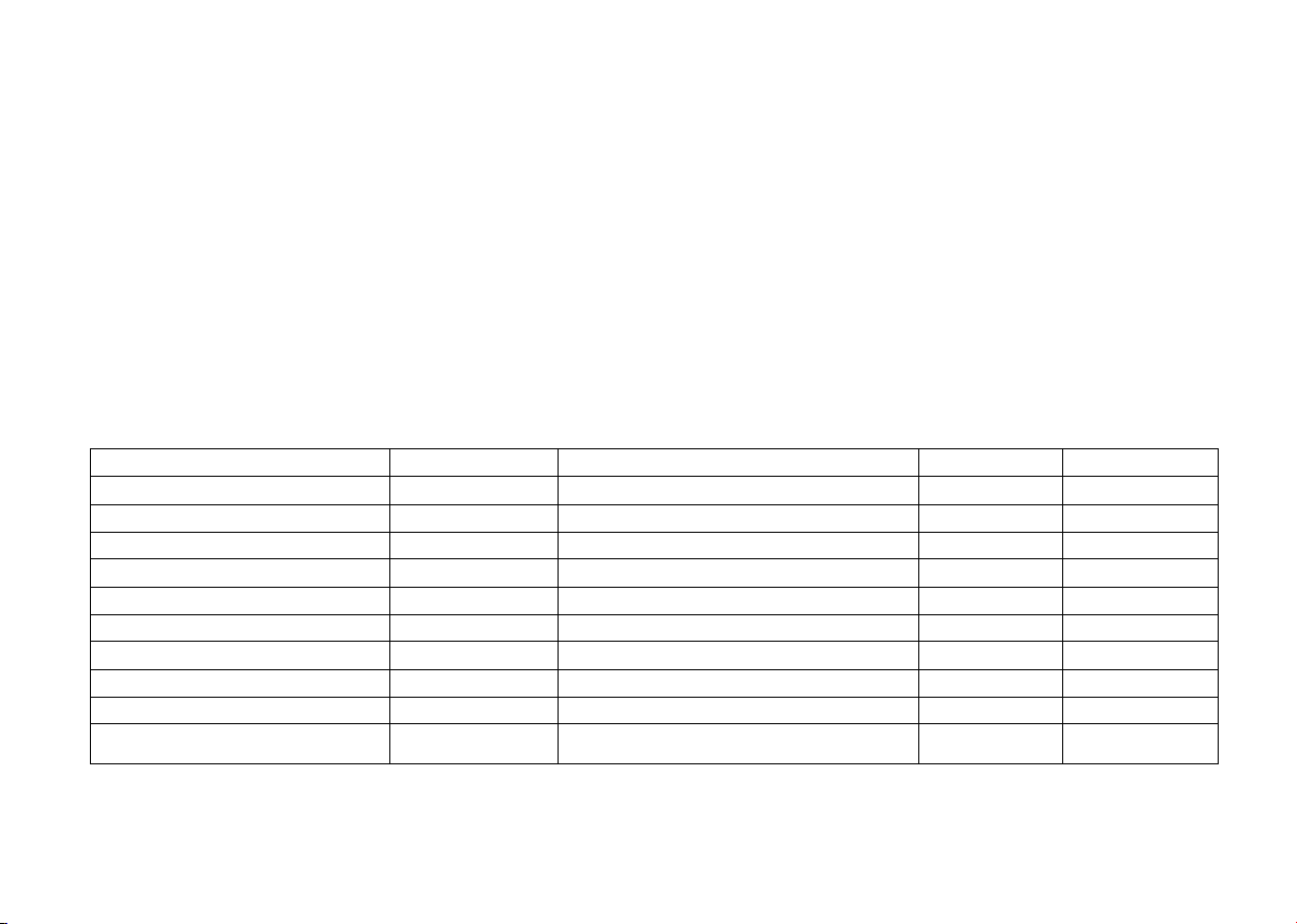
PERIODIC MAINTENANCE RECORD
* A vehicle usually driven in any disadvantageous environment such as dust shall be maintained according to a short cycle in order to keep
the vehicle's performance.
Reference Mileage for Service Actual Mileage Date Service Item Dealer's Stamp
250m
500m
1,000m
1,500m
2,000m
2,500m
3,000m
3,500m
4,000m
4,500m
_____ (MMM) ___ (DD) _____ (YYYY)
_____ (MMM) ___ (DD) _____ (YYYY)
_____ (MMM) ___ (DD) _____ (YYYY)
_____ (MMM) ___ (DD) _____ (YYYY)
_____ (MMM) ___ (DD) _____ (YYYY)
_____ (MMM) ___ (DD) _____ (YYYY)
_____ (MMM) ___ (DD) _____ (YYYY)
_____ (MMM) ___ (DD) _____ (YYYY)
_____ (MMM) ___ (DD) _____ (YYYY)
_____ (MMM) ___ (DD) _____ (YYYY)
37
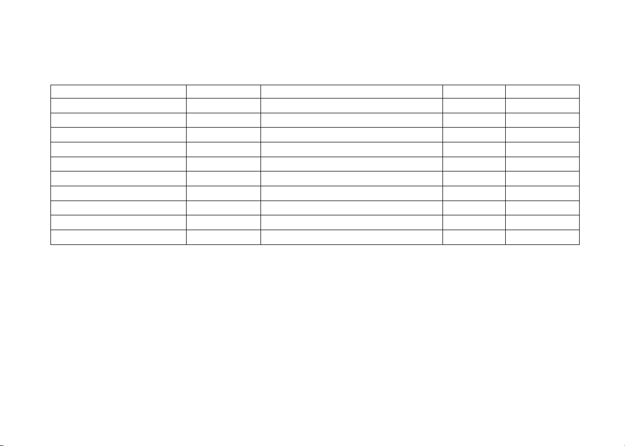
PERIODIC MAINTENANCE RECORD
* Copy the periodic maintenance record for further applications, if necessary.
Reference Mileage for Service Actual Mileage Date Service Item Dealer's Stamp
5,000m
5,500m
6,000m
6,500m
7,000m
7,500m
8,000m
8,500m
9,000m
9,500m
_____ (MMM) ___ (DD) _____ (YYYY)
_____ (MMM) ___ (DD) _____ (YYYY)
_____ (MMM) ___ (DD) _____ (YYYY)
_____ (MMM) ___ (DD) _____ (YYYY)
_____ (MMM) ___ (DD) _____ (YYYY)
_____ (MMM) ___ (DD) _____ (YYYY)
_____ (MMM) ___ (DD) _____ (YYYY)
_____ (MMM) ___ (DD) _____ (YYYY)
_____ (MMM) ___ (DD) _____ (YYYY)
_____ (MMM) ___ (DD) _____ (YYYY)
38
 Loading...