

Page 1
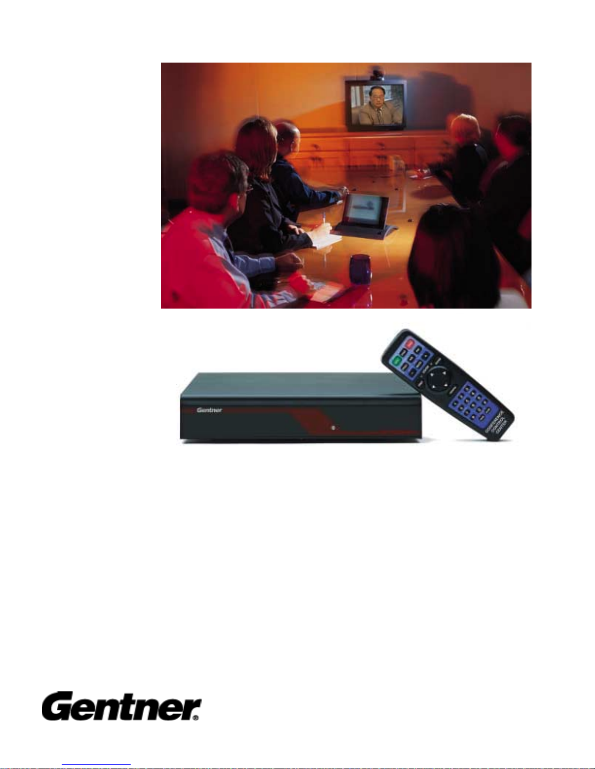
APV200-IP
Audio Perfect Video 200- IP
Perfect Communication through Te chnology, Servi ce and Education.
V.35 Manual
Page 2

Table of Contents
Before you begin................................................................................................3
Where do I start.................................................................................................. 3
Connectivity ....................................................................................................4
Remote control...................................................................................................5
The Setup Genie................................................................................................. 6
Optional IR Remote Pick-up............................................................................12
Local and remote camera control.....................................................................13
Camera presets ................................................................................................. 13
V.35 ..................................................................................................14
Additional Configurations................................................................................16
External FIFO ..................................................................................................17
Auto Dial Features ...........................................................................................17
Loopback Test..................................................................................................18
Typical Applications........................................................................................19
Leased Line Manual Dial / Manual Answer..............................................20
Leased Line Auto Dial / Auto Answer ...................................................... 21
DTR Automatic Dialing Method...............................................................22
Leased Line Application............................................................................23
Dial Up Applications..................................................................................24
Satellite Applications.................................................................................27
V.35 2
Page 3

Before You Begin
Visually inspect the equipment that you have received for any damages. If any damage is
noticed, call Gentner's Technical Support Department at (800)283-5936 to request a Return Material
Authorization (RMA) number. All returns must be packed in their original shipping containers
and must be properly marked and identified with an RMA number.
You will need to obtain a power cord from your local electrical parts supplier if you do not live
in the United States, United Kingdom, Switzerland or Europe (CE).
Where Do I Start?
(The do it yourself basics)
Carefully review this Users Guide before you begin your installation. Exercise every safety
precaution in your installation to protect yourself and your investment.
Make sure you have a live network connection and the appropriate network configuration
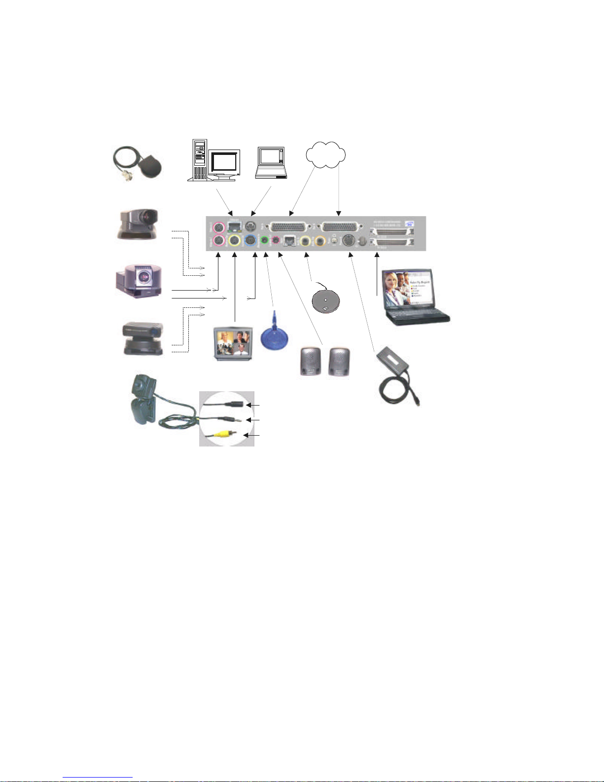
information. Refer to the connection guide to assemble your hardware.
Familiarize yourself with the hand held Remote Control before you power on your
APV200IP and start your configuration setup.
V.35 3
Page 4
Connectivity
V.35 Cables
Optional Remote
IR Pick-up
Sony Camera
Panasonic Camera
Canon Camera
Clip Camera
S-Video
Camera Control
EtherNet
Camera S-Video
TV Monitor
Net Meeting
Camera Control
Standard
Mic
To Camera Power
Cube (adapter)
To codec Microphone In
To S-video adapter cable
(codec video in)
Platter Mic
Standard
Speakers
SCSI
Power Supply
V.35 4
Turn on the camera.
Turn on the monitor.
Turn on the APV200IP.
Page 5
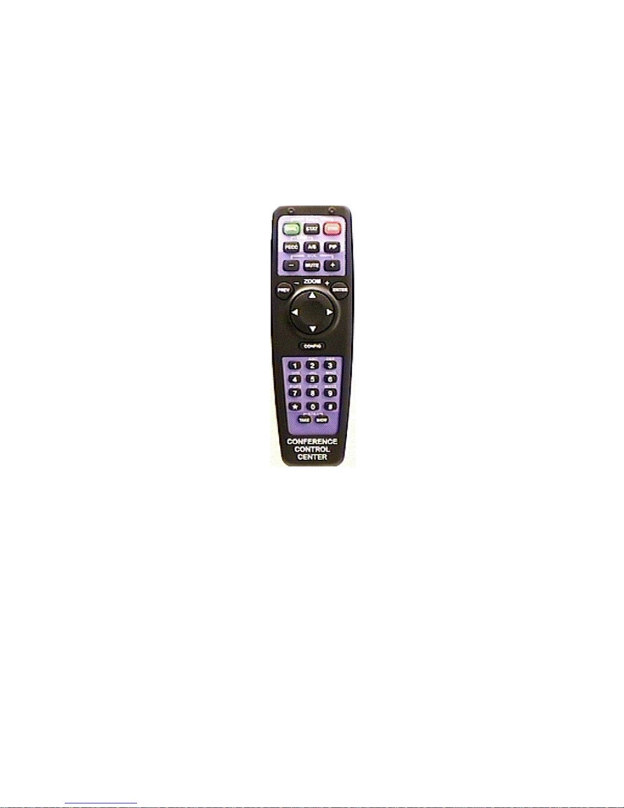
Remote Control
V.35 5
Page 6
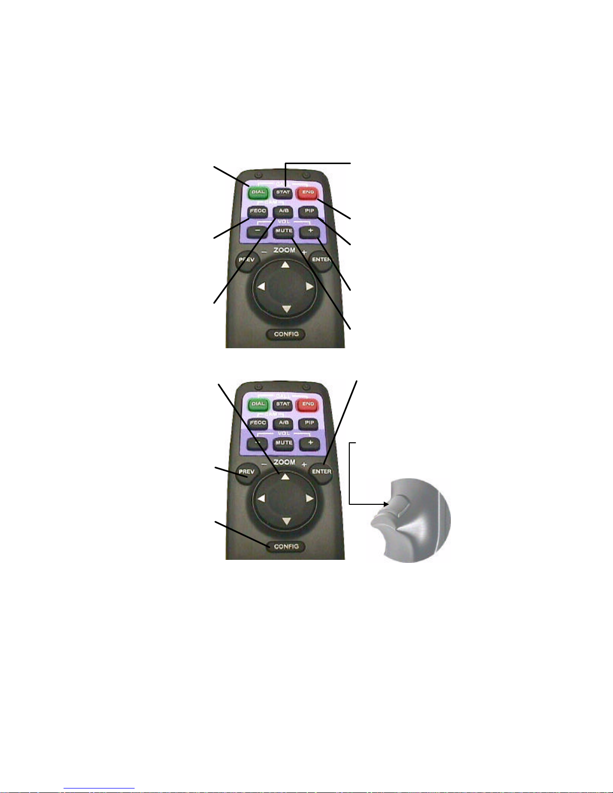
Manual dial, redial, speed dial,
DIAL
or use a video phonebook to
make calls. Allows you to get
information about the remote
control, Gentner, or the
APV200IP.
STAT
Shows all important call
information such as transfer,
audio and video rates.
END
Hangs up the current call.
Far End Camera Control
FECC
Pressing this allows you to
control the remote camera,
pan, tilt, zoom and presets.
A/B
Allows you to switch
between the two camera
inputs, or up to 16 remote
inputs.
UP, DOWN,
LEFT, RIGHT
Manipulates the menu items.
Pan and tilt functions for
camera when no menu is
showing.
PREV (ZOOM-)
Goes to the previous menu.
Zooms camera out when no
menu is showing.
CONFIG
Allows you to configure
your system setup options.
PIP
Allows you to position
the picture-in-picture
around the screen.
VOLUME
Adjusts the speaker or line
out level.
MUTE
Mutes the microphone
or line input.
ENTER
Used in menu functions that
say "press ENTER."
Zooms camera in when no
menu is showing.
VIDEO TRIGGER
This will show video at any
time when a menu is
showing.
V.35 6
Page 7
Configuration
There are 3 different network configuration options available on the V.35 APV200IP. The 3
options are Leased line (T1, E1, PRI), RS-366 dialing (for dialing video numbers), and DTR
dialing (for numbers stored in the IMUX). To assist in the proper setup and configuration, a
brief description of each menu option specific toV.35 configuration is shown in this document.
Please refer to your Gentner APV200IP manual for all other menus and their respective
descriptions.
The Setup Genie
After initial power on and boot up, you will enter the Setup Genie. Follow all instructions
carefully.
You can make your desired selection by using the < > buttons on the remote control.
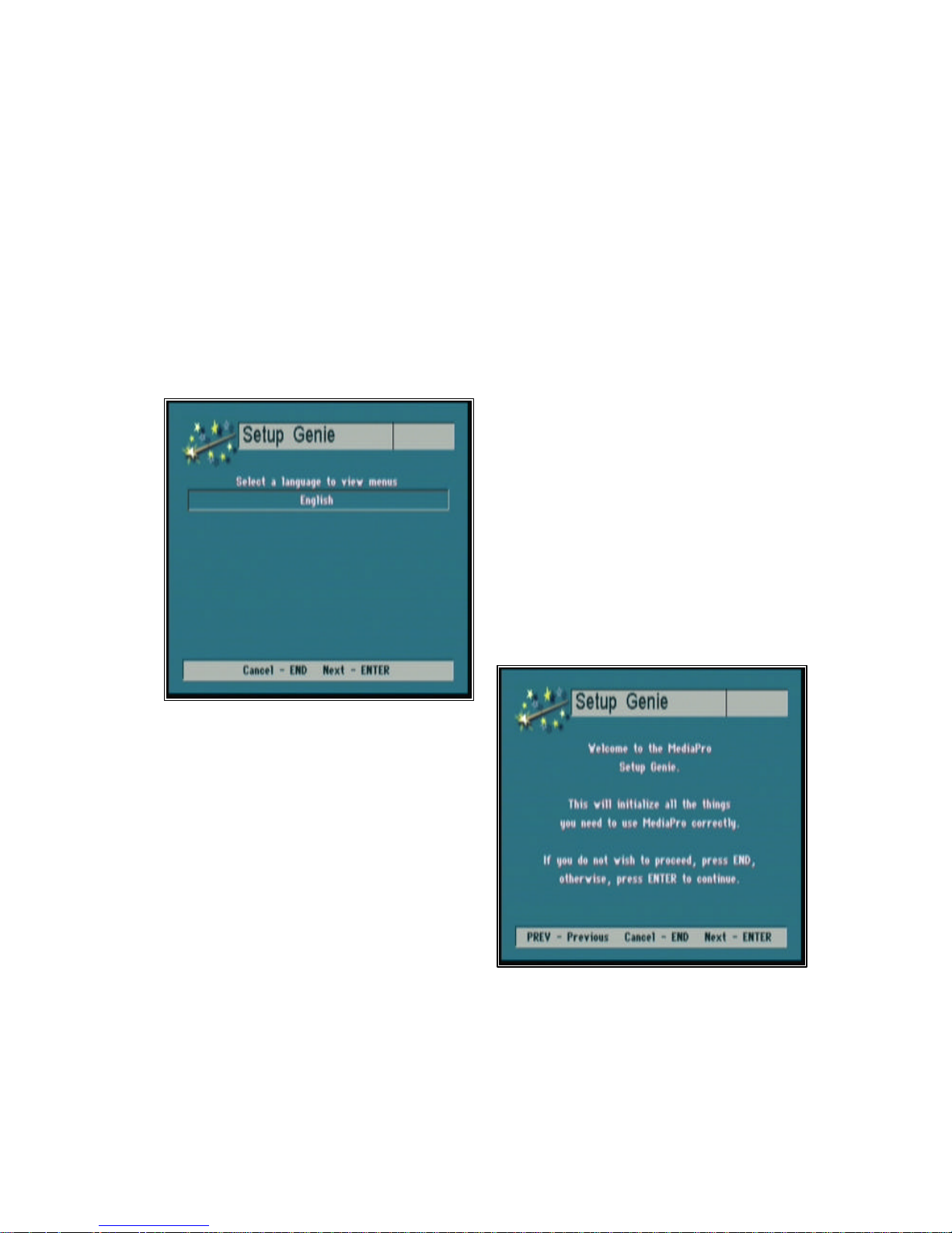
Step 1. Select your language of choice. Press
Enter to continue. English is the only option
at this time.
Step 2. To begin follow the Setup Genie’s
instructions carefully. Press Enter to continue.
V.35 7
Page 8
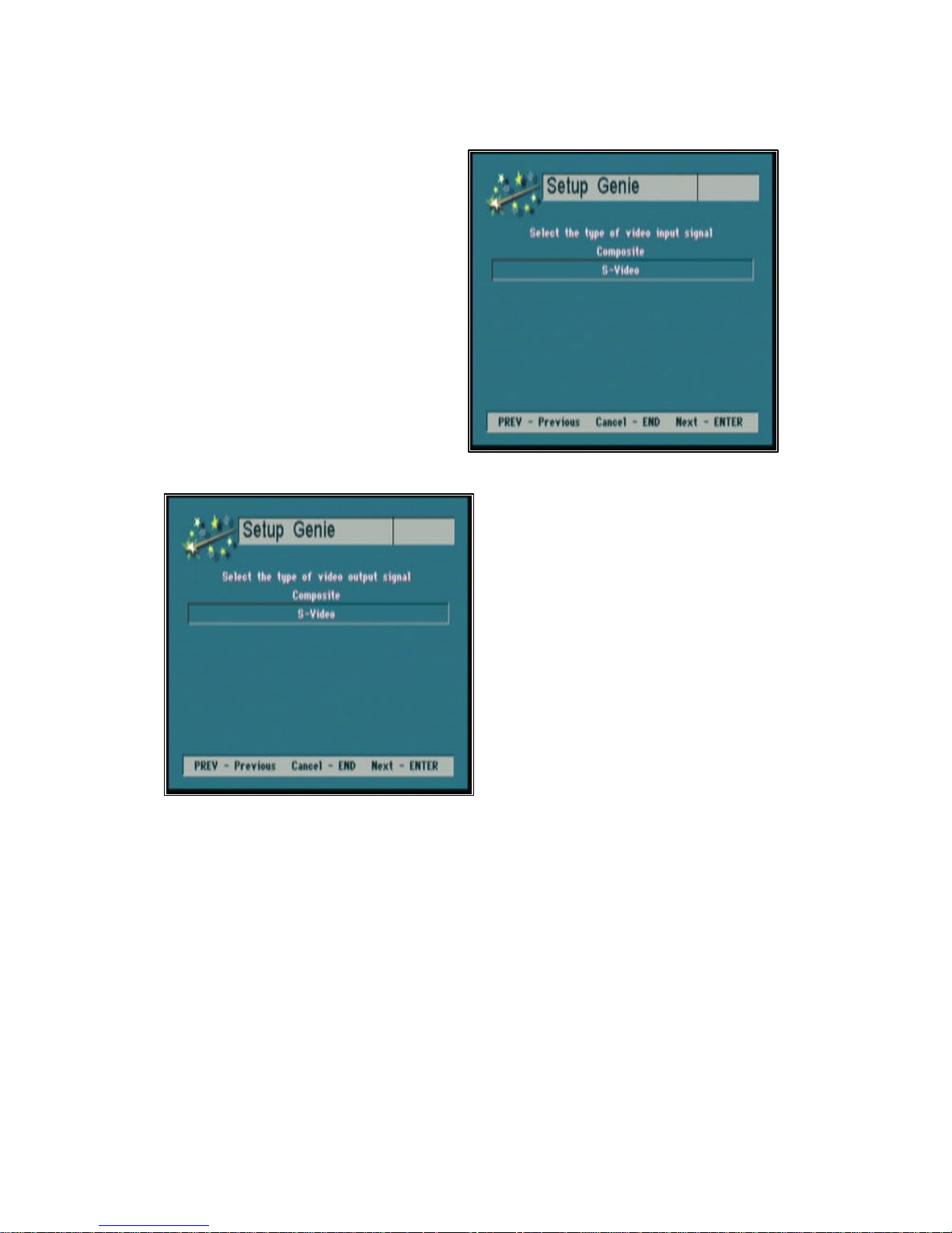
Step 3. Using the up/down (tu) arrow
buttons select the type of video signal your
primary input device (camera, VCR) will
provide. Press Enter to continue.
Step 4. Using the up/down (tu) arrow
buttons select the type of video signal your
display device (TV, monitor) requires. Press
Enter to continue.
V.35 8
Page 9
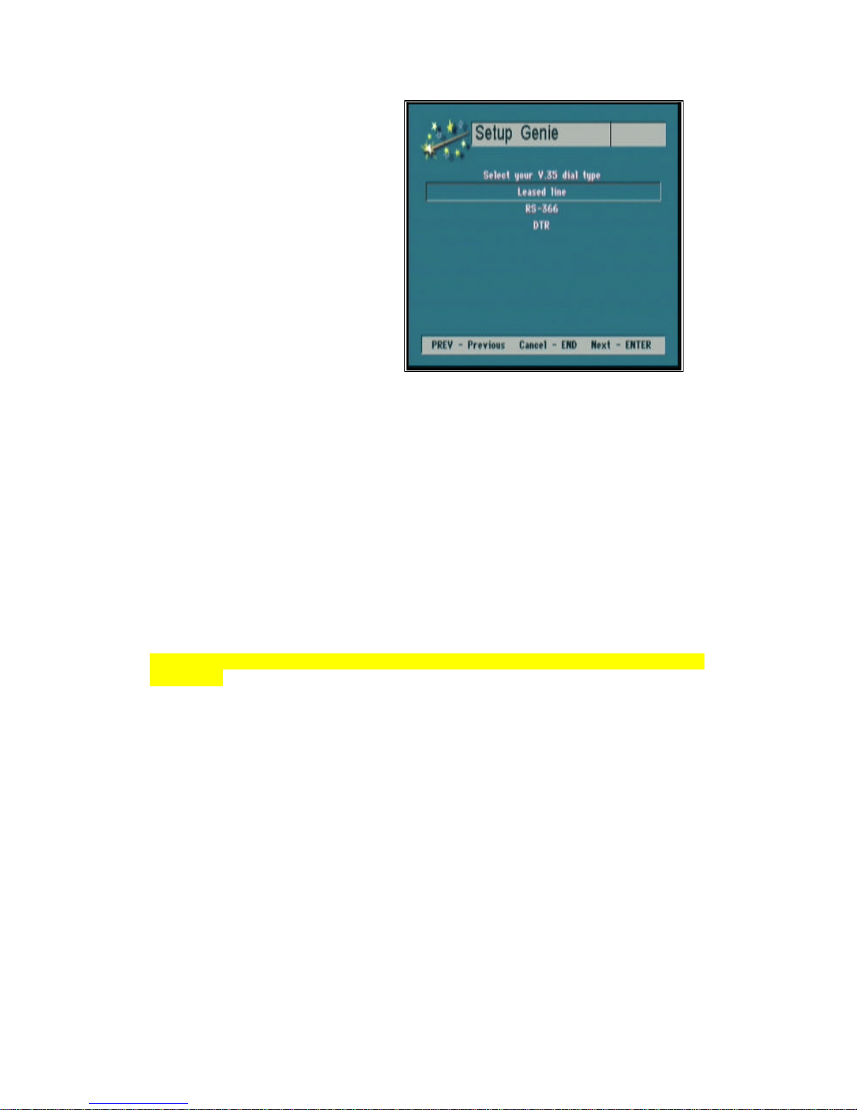
Step 5. Using the up/down (tu) arrow
buttons select your V.35 dial type. Press
Enter to continue.
Selecting the Leased line option
This is a direct connection from one location to another location, there are no dialing capabilities.
The V.35 APV200IP can only connect to the location at the other end of the leased telephone
line or private network. Select this option when the V.35 APV200IP is attached to a
CSU/DSU or DCE device. Only Port A on the V.35 APV200IP is connected. The RS366
interface is not used for this application.
Selecting the RS-366 option
This allows you to dial to any location using an external DCE network device or IMUX. The
external DCE device must have an RS-366 connection. The dial digits are sent to the DCE via
the RS366 interface. When dialing an H.221 call Port A and B are both used, where bonded
calls use only Port A. Select this option when attaching to an IMUX. The IMUX must be
configured for RS366 dialing.
Note: The set up and configuration of the IMUX is the responsibility of the systems integrator or
the end user.
Selecting the DTR option
Select this option to instruct the APV200IP to raise the Data Terminal Ready (DTR)
interface signal to place a call to a telephone number stored in the IMUX. The IMUX must be
configured for DTR dialing and have the telephone number stored in its call directory. In this
application, the APV200IP does not send dial digits to the IMUX.
V.35 9
Page 10
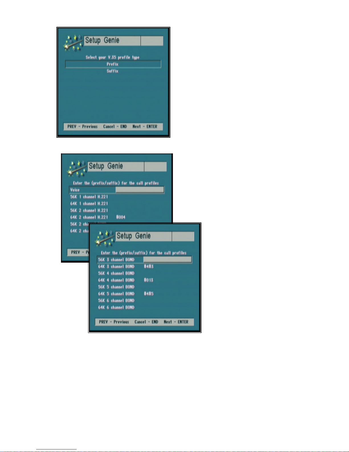
Step 6. Using the up/down (tu) arrow
buttons select your profile type. Press Enter to
continue.
Selecting the correct Profile type
Consult your DCE equipment manufacturer’s
documentation to determine if a prefix or suffix
is required in the call profile to activate the RS366 dialing procedure.
Step 7. Enter your call profile information for
the type of calls that you make. Use the left
(w) arrow button to backspace and the
up/down (tu) arrow buttons to advance to
the next line. Press Enter to continue.
Selecting the correct Call Profiles
Consult your DCE equipment
manufacturer’s documentation to
determine if a prefix or suffix is
required in the call profile to
activate the RS-366 dialing
procedure.
V.35 10
Example:
In the Call profiles menu, select
64K 2 channel BOND, and enter
#012. In the
Dial menu, when you select the
call type of 2Ch 64K (128), the
#012 will automatically be added
to the dialing string.
Page 11
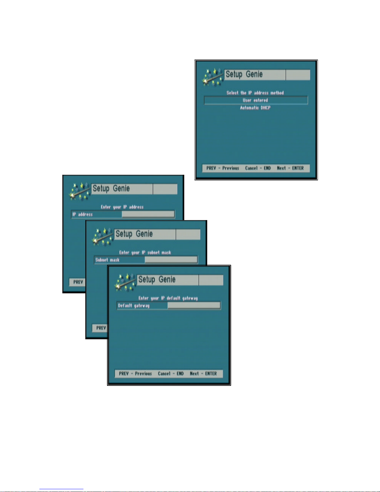
IP Information is for Ethernet equipped units only. Consult your IS
manager for the correct settings.
Step 8. IP address is for Ethernet equipped units
only, consult your IS manager for correct
selection. Using the up/down (tu) arrow
buttons select your IP address method. Press
Enter to continue.
V.35 11
Step 9. Enter IP address. Use ‘*’ to
enter the decimal point. Press Enter to
continue.
Repeat for IP Subnet mask
and IP Default gateway
entries.
Page 12
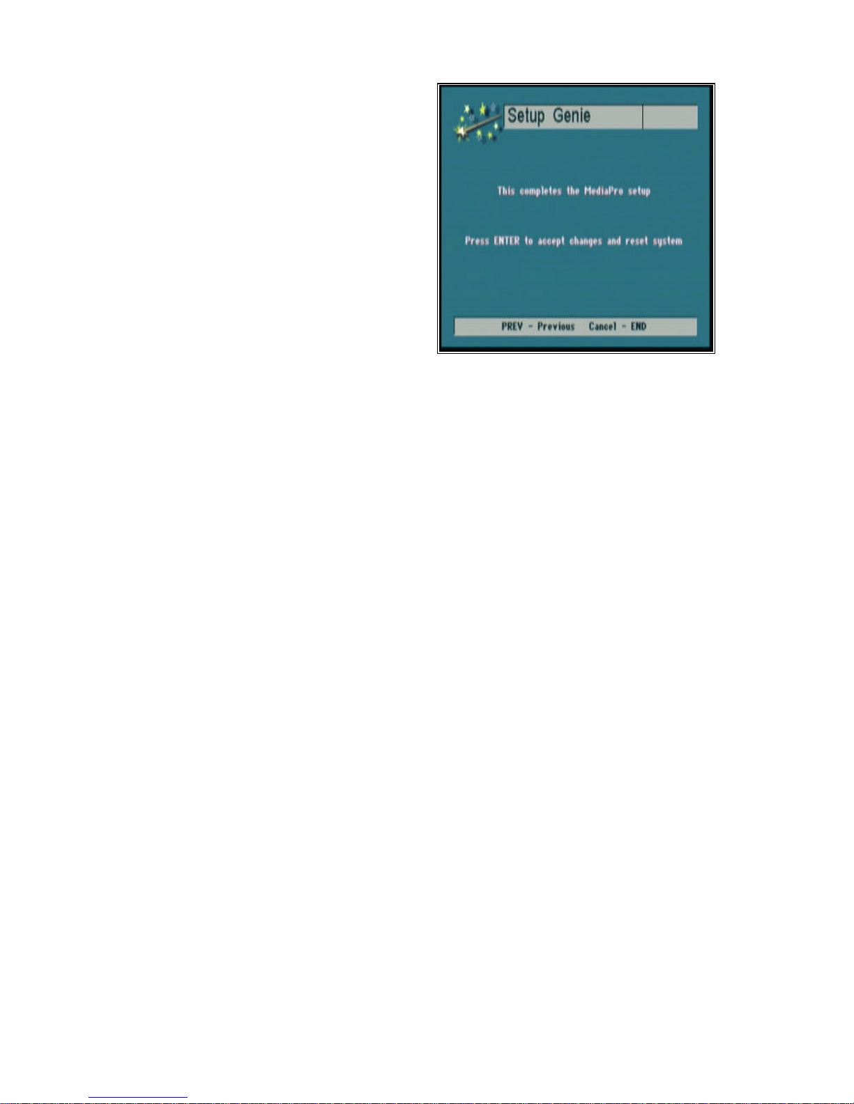
Step 10. Setup is now complete. You are ready
to proceed with your first video call. Press
Enter to continue.
Note: After pressing Enter your system will
automatically reset.
Optional Remote IR Pick-up
The Optional Remote IR Pick-Up connects to the REM IR jack on the back panel of the
APV200IP. The Remote IR allows you to place the APV200IP out of site (assuming
that you have a clear view from the remote control to the Remote IR).
V.35 12
Page 13

Local and remote camera control
Below are instructions to set up local camera control. If you call and connect to another video
conferencing system you may be able to control their camera as well.
To control the local camera (your camera), press:
pans up
pans down
pans left
pans right
PREV (– ZOOM) zooms out
ENTER (+ ZOOM) zooms in
To control the remote camera, press FECC on the remote control. A far camera icon will appear
on your screen. Use the same up, down, left and right buttons to pan and the PREV and ENTER
to zoom.
Note: If you are unable to control a remote camera it is possible that the person you are calling
does not allow a remote caller to control their camera.
Camera presets
Presets can be set for both the local or remote cameras. The local presets will be saved if you
lose power to the APV200IP. The remote presets will be lost when the call is terminated.
To store a local preset, position the camera on an image you would like to save. Using the
number pad, press and hold the number you want to store. The status bar will appear with a
“Preset stored” message.
To control the remote camera press FECC on the remote control. A far camera icon will appear
on your screen. Position the camera on an image you would like to save. Using the number pad,
press and hold the number you want to store. The status bar will appear with a “Preset stored”
message. Remote presets are lost when the call is terminated.
V.35 13
Page 14

V.35
The V.35 APV200IP has been introduced to accommodate Non-ISDN BRI applications
through the use of external network equipment. This APV200IP has two high-density, HD44 high-speed serial data ports, which can be configured to operate as a V.35, RS449, or RS530
interface. In addition, the V.35 APV200IP has two integrated RS366 dialing interfaces.
The V.35 APV200IP is a Data Terminal Equipment (DTE) device and connects to a wide
variety of external V.35/RS449/RS530 Data Communication Equipment (DCE) devices using
RSI cable sets. The V.35 APV200IP does not have a built in IMUX or telephone network
interface.
The V.35 APV200IP supports operation on leased (dedicated) digital telephone lines, dial-up
(PSTN) digital lines, or over a satellite link. An encryption device may be installed between the
APV200IP V.35 port and the DCE device to provide secure video conferencing. The V.35
APV200IP operates at bit rates of 56Kbps to 384Kbps. The bit rate must be a multiple of
56Kbps or 64Kbps.
Gentner supplies cable sets for attachment to various DCE devices. The interface cable set must be
ordered separately with each V.35 APV200IP. Each set consists of two cables. Use the
following chart to order the correct cable set:
Part
Cable number DTE DCE
RS530/RS366 830-000-029 DSUB 44M (2) DSUB 25M
RS449/RS366 830-000-027 DSUB 44M RS366 (1) DSUB 25M
(Y-cable) RS449 (1) DSUB 37M
V.35/RS366 830-000-028 DSUB 44M RS366 (1) DSUB 25M
(Y-cable for use with ADTRAN CSU/DSU) V.35 (1) Winchester 34M
Direct connect to 830-000-026 DSUB 44M (1) DSUB 44M
an Ascend IMUX
V.35 14
Page 15
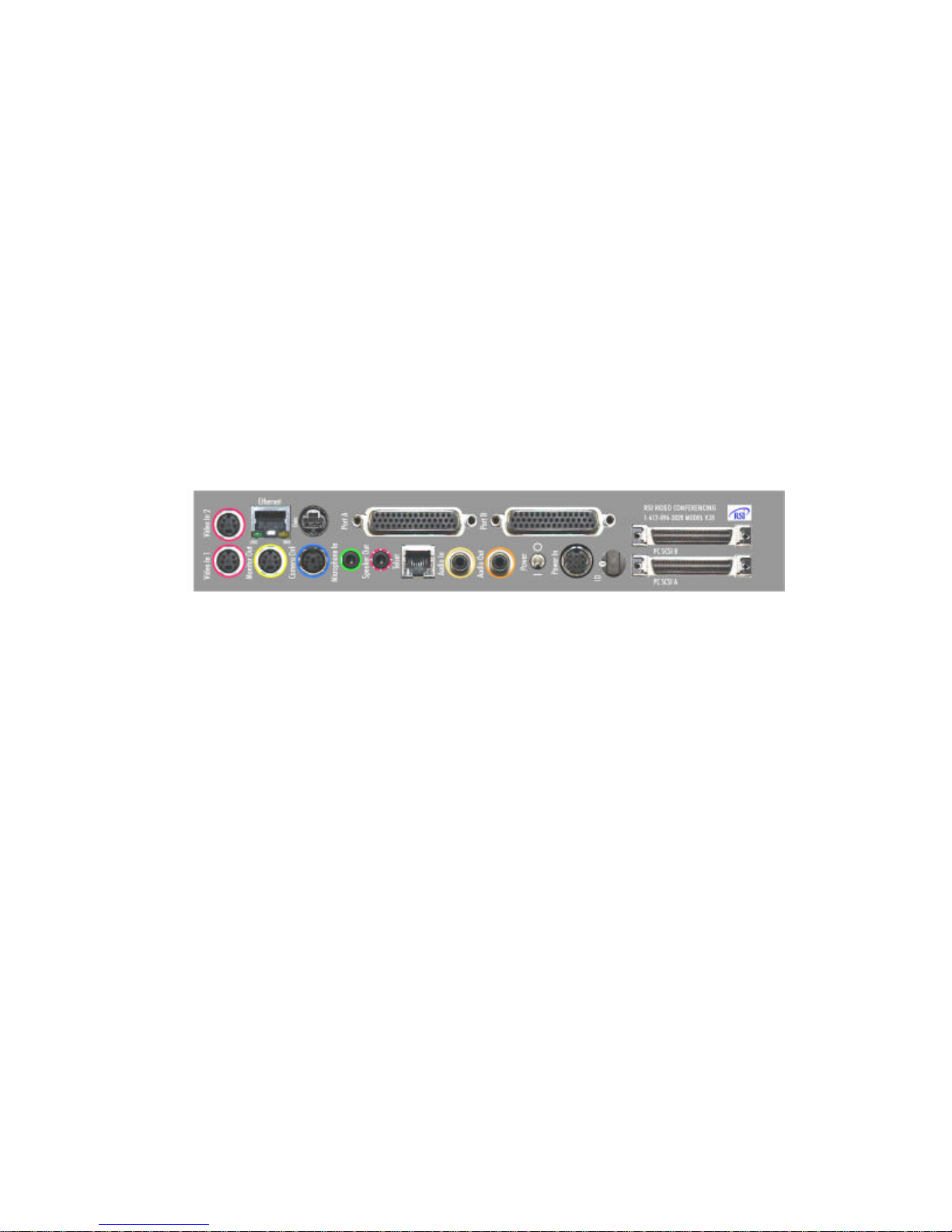
The V.35 APV200IP has two HD-44 data/dialing ports, Port A and Port B (see below). Port
A is the primary serial data port and is used for all incoming and outgoing calls. Port B is the
secondary serial data port and is used for the second channel in H.221 calls.
The DCE device will direct incoming H.221 calls to Port A and/or Port B. The DCE device will
direct incoming bonded calls to Port A.
A typical DCE device will have a MASTER or Primary port, which connects to the
APV200IP
connects to theAPV200IP
Port A. Some DCE devices will have a SLAVE or Secondary port, which
Port B. The actual DCE device port names vary with the
manufacturer. An external IMUX is considered a DCE device.
V.35 15
Page 16
Additional Configurations
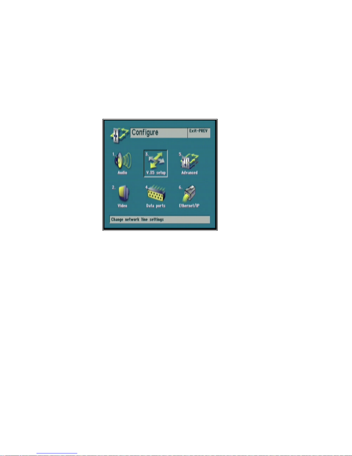
You may find it necessary to make additional setting changes in the V.35 configuration. Press
the CONFIG button and select V.35 setup.
V.35 16
Page 17
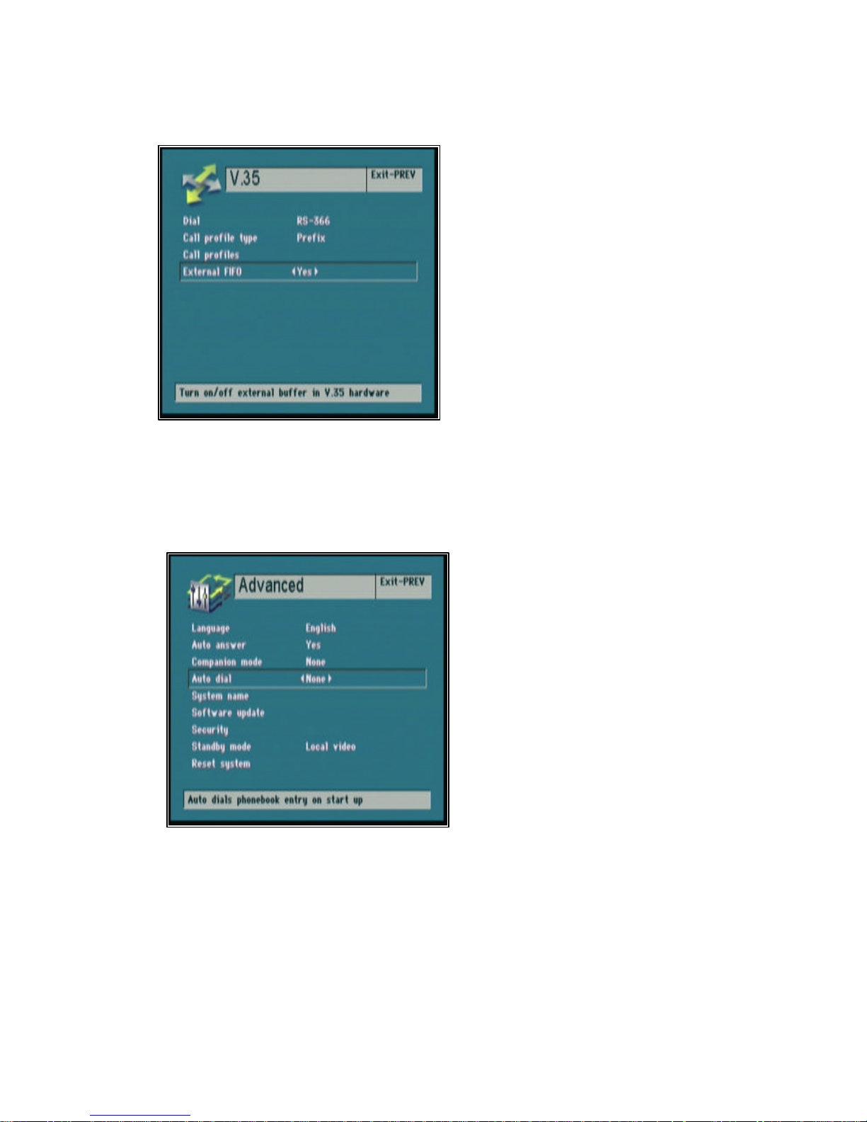
Selecting the External FIFO option
Selecting the Auto dial feature
This option must always be set to Yes.
V.35 17
Select None to Disable the Auto dial
feature.
To Enable the Auto dial feature select 1, 2,
or 3 to instruct the APV200IP to
automatically dial the number in the
phonebook position 1, 2, or 3.
Note: Any menu setting changes made will
not be saved while a call is active, the call
must be terminated so changes can be
saved.
Page 18
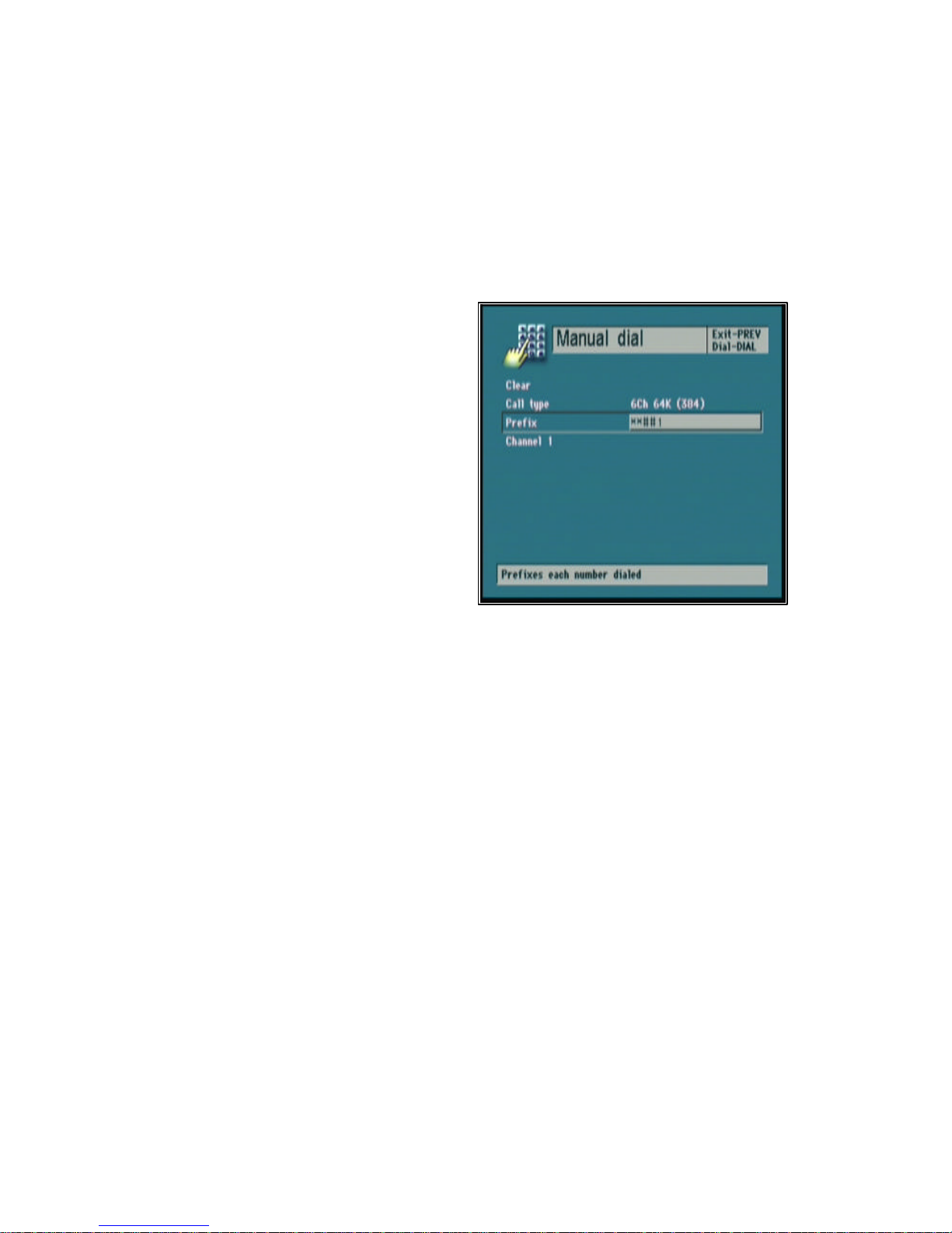
Performing an Interface Loop back
This will verify the APV200IP’s functional operation.
Note: Mute the microphone or have the speakers very low or feedback will occur.
Step 1
Press the DIAL button on the remote control
and select the Manual dial option from the
Manual dial menu.
Step 2
Select the appropriate Call type, for example
6Ch 64K (384). APV200IP will loop
back the number of channels requested.
Step 3
In the Prefix enter the string **##1.
Step 4
Press the DIAL button to dial the Loop back
entry.
Step 5
The Loop back call will stay connected until terminated by pressing the HANG UP button on the
remote control.
V.35 18
Page 19

Typical applications
V.35 19
Page 20

Leased Line Manual Dial/Manual Answer
Setup
1. Attach the proper Gentner interface cable to Port A on the back of the APV200IP.
2. Press the CONFIG button on the IR controller to enter the Configure menu.
3. Select V.35 setup by pressing 3.
4. Scroll through the Dial options and select Leased line. Press PREV to exit this menu.
5. Select Advanced by pressing 5.
6. Scroll down to Auto Answer and the select NO option.
7. Scroll down to Auto Dial and the select None option. Press PREV to exit this menu.
8. Select Advanced again by pressing 5.
9. Scroll down to Reset system and press the ENTER. Your system will now automatically
reset.
Establishing a connection:
1. Press the DIAL button on the IR Controller.
2. You will then be prompted to press DIAL again.
3. Wait until the call is either automatically or manually answered at the remote site.
Answering a call in manual mode:
Upon hearing the ring and seeing the prompt press ENTER to answer the call.
Terminating a call:
To disconnect the call, press the HANGUP button.
V.35 20
Page 21

Leased Line Auto Dial/Auto Answer
Setup
1. Attach the proper Gentner interface cable to Port A on the back of the APV200IP.
2. Press the CONFIG button on the IR controller to enter the Configure menu.
3. Select V.35 setup by pressing 3.
4. Scroll through the Dial options and select Leased line. Press PREV to exit this menu.
5. Select Advanced by pressing 5.
6. Scroll down to Auto Answer and the select Yes option.
7. Scroll down to Auto Dial and the select 1 option. Press PREV to exit this menu.
8. Select Advanced again by pressing 5.
9. Scroll down to Reset system and press the ENTER. Your system will now automatically
reset.
Establishing a connection:
If the remote site is properly connected to the network and configured for auto answer, this
application will automatically establish a connection with that remote site upon power up and
restoration of a network disruption.
Answering a call in Auto Dial mode:
Not applicable, this application will always attempt to originate a call.
Terminating a call:
This application will not allow a call to be permanently terminated. Should a network disruption
terminate the call it will be only temporary, the APV200IP will automatically attempt to reestablish the call.
V.35 21
Page 22

DTR Automatic Dialing Method
Setup
1. Attach the proper Gentner interface cable to Port A on the back of the APV200IP. If H.221
calls will be made, attach the proper RSI interface cables to Ports A & B.
2. Press the CONFIG button on the IR controller to enter the Configure menu.
3. Select V.35 setup by pressing 3.
4. Scroll through the Dial options and select DTR. Press PREV to exit this menu.
5. Select Advanced by pressing 5.
6. Scroll down to Auto Answer and select either Yes or No.
7. Select Advanced again by pressing 5.
8. Scroll down to Reset system and press the ENTER. Your system will now automatically
reset.
Establishing a connection:
1. Press the DIAL button on the IR controller
2. Select Manual Dial
3. Press the DIAL button on the IR controller. The number that has been previously stored in
the IMUX will be called.
Answering a call:
If the Auto Answer is set to Yes an incoming call will be answered, if it is set to No you will
need to press the ENTER button on the IR controller to answer the call.
Terminating a call:
To end a call, press the END button on the IR controller.
V.35 22
Page 23

Leased Line application:
DCE - Adtran TSU LT (T1-FT1 Data/Channel Service Unit)
Gentner Cables:
1 – Gentner to V.35 cable (part #830-000-028).
Connect the end of the cable labeled Video Codec to the V.35 APV200IPPort A connector.
Connect the V.35 connector to the Adtran V.35 port. The RS366 cable is not connected in this
application.
DCE configuration:
Follow manufacturer instructions to select the number and type of T1 time slots to be used. This
must agree with the usage at the remote end. The TSU may supply timing to the Network (T1)
connection, or may derive timing from it. The APV200IP (DTE) does not provide T1 timing.
The APV200IP will support 1 to 6 time slots, either 56 or 64kbps.
APV200IP configuration:
V.35 Menu:
Dial: Leased Line
Operation:
Dial the call.
The call stays connected until hung up by the user.
Once the other end answers, audio and video will flow.
Push the Hang Up button twice to disconnect the call.
DCE Configuration – refer to the manufacturer’s instructions.
V.35 23
Page 24

Dial Up Application:
DCE - Ascend Multiband VSX BRI, refer to the manufacturer’s instructions.
Gentner Cables:
2 – Gentner to Ascend cables, part number 830-000-026.
Connect one cable from the V.35 APV200IP
other cable from the V.35 APV200IP
Note: Make sure the end of the cable labeled Video Codec is attached to the V.35
APV200IP. The connectors on each end of the cable look the same but the wiring of the
cable is different at each end. The other end is connected to the IMUX.
DCE configuration:
Follow the manufacturer’s instructions to configure the IMUX. The parameters recommended
for operation with RSI V.35 APV200IP
Configure:
Dial RS-366 Ext. 1
Clear DTR Inactive
Early CD None
Advanced
Dual Port 1&2 Dual.
Port A to the Ascend Host 1 port. Connect the
Port B to the Ascend Host 2 port.
must be set as shown below:
Directory:
The factory default directory contains the following call profiles:
01 1 port, 56k
02 1 port, 64k
03 2 port, 56k
04 2 port, 64k
05 Bond 56x8
06 Bond 64x8
The first four entries are used for H.221 dialing. The 05 and 06 entries will attempt to dial 8
channel bonding calls if the remote device has 8 channels capacity. Entries 05 and 06 will not
work with the APV200IP
Create two or more profiles, identical to 05 and 06 with channel counts of 6 or less.
V.35 24
since it supports a maximum of 6 channels.
Page 25

For example, create an entry 13:
Name Bond 56x6
Dial # (anything, the APV200IP
Call Type BONDING
Call Mgmt Mode 1
Data Svc 56K
Force 56 No
Base Ch Count 6
Inc Ch Count N/A
Dec Ch Count N/A
Bill # (nothing)
Call Password (nothing)
Or, create an entry 14:
Name Bond 64x6
Dial # (anything, the APV200IP
Call Type BONDING
Call Mgmt Mode 1
Data Svc 64K
Force 56 No
Base Ch Count 6
Inc Ch Count N/A
Dec Ch Count N/A
Bill # (nothing)
Call Password (nothing)
will override via RS-366 dialer)
will override via RS-366 dialer)
The example call profiles shown above will work when calling an Gentner ISDN
APV200IP and
other H.320 bonding video conferencing devices. Some of the Ascend profiles support the use of
Ascend’s proprietary AIM protocol. The AIM protocol can only be used between compatible
Ascend IMUX’s. Gentner does not recommend using the AIM protocol since the call will fail if the
remote IMUX does not support AIM. The above profiles will work with an attached Gentner V.35
APV200IP if the channel count is 6 channels or less.
When a call is initiated, the maximum channel rate (64/56) and the maximum channel count (6
or less) are set by the call profile. The remote terminal may negotiate lower connection rate and
channel count.
V.35 25
Page 26

APV200IP configuration:
V.35 Menu:
Dial: RS-366
Call Profile Type: Prefix
Call Profiles:
56K 2 channel H.221 #003
64K 2 channel H.221 #004
56K 6 channel BOND #013
64K 2 channel BOND #014
External FIFO: Yes
Placing a Call:
1. Press DIAL
2. Press ENTER to select Manual Dial.
3. Press ENTER to clear the manual dial menus and set the Call profile to 6Ch 64K (384)
4. Scroll down to Channel 1 and enter the telephone number that you want to call, for example
18018868834.
5. Press DIAL again to initiate the call.
The Connection status menu will appear. The IMUX connects first then the APV200IP will
connect. Once the call has been established, you will see video and hear the audio from the
remote end. To terminate the call, push the HANG UP button twice.
WAIT PROCEEDING indicates the RS-366 dialer is active. Once the call is placed, the IMUX
does all the work until the H.221 channels are cut through to the APV200IP
or the bonding
completes and connects a single high speed channel to the APV200IP. Upon completing the
establishment of the call, the call status menu will show Port A connected and Port B inactive.
If the IMUX fails to complete the calls, a FACILITY REJECTED cause code results.
After the IMUX asserts Carrier Detect, the APV200IP
channels are connected and at what rate (56/64). The APV200IP
will learn from the IMUX how many
will then negotiate H.221
and start video. It will place a second H.221 call if the entry so specified.
If a call fails please refer to the IMUX manufacture’s instructions for cause code information.
V.35 26
Page 27

Satellite Applications:
The V.35 APV200IP has been demonstrated to work with several satellite installations.
However, since there are a wide variety of satellite modems, timing, network design and other
factors, Gentner cannot guarantee proper video operation with every satellite installation.
Since Gentner does not have its own satellite service, Gentner is willing assist the user in determining if
the V.35 APV200IP is suitable for the application.
Gentner must be provided with the following information:
1. An overview of the proposed application.
2. A network diagram of the proposed application
3. A list of the modem and network equipment that will be attached to the APV200IP
including specifications.
4. A technical support contact familiar with the satellite equipment.
V.35 27
 Loading...