

Page 1

Introduction.....................................................3
Unpacking..............................................................................................4
Warranty Instructions....................................................................................4
Installation......................................................7
Operation.........................................................9
Remote Control Buttons.....................................................................................11
Place a Call............................................................................................................11
End a Call................................................................................................................11
Adjust the Volume in the Room.....................................................................11
Mute Microphones........................................................................................... .11
Turn off Mute........................................................................................................11
Access Features from a PBX.........................................................................11
Redial the Last Telephone Number Dialed..............................................11
Dial a Number Stored in Speed Dial............................................................12
Customize your AP IR Remote Control System......................................12
Programming.................................................13
Baud Rate.................................................................................................................13
Speed Dial................................................................................................................14
Telephone Device................................................................................................14
Mute............................................................................................................................15
Volume.......................................................................................................................16
Volume Range/Step Size...................................................................................18
Hook Flash...............................................................................................................18
Reset to Default......................................................................................................18
Appendices....................................................19
Specifications.........................................................................................................19
Warranty.........................................................................................................20
FCC Part 15 Compliance...................................................................................21
able of Contents
T
TECHNICAL SUPPORT: 1.800.283.5936 (USA) OR 1.801.974.3760
1
Page 2

TECHNICAL SUPPORT: 1.800.283.5936 (USA) OR 1.801.974.3760
2
Page 3

1
TECHNICAL SUPPORT: 1.800.283.5936 (USA) OR 1.801.974.3760
3
The AP IR Remote Control System is designed to allow easy operation
of all your Audio Perfect products from your desk or conference table,
rather than from the front panel of your Gentner audio conferencing
products.
It is made up of two components, the handheld infrared transmitter
(remote control) and the base station infrared receiver. The transmitter
is used to operate or customize the many features of the Audio Perfect
system, such as: connect, disconnect, dial a telephone number, redial,
store speed dial numbers, activate speed dial, hook flash, adjust
volume, and mute the microphones.
The AP IR Remote functions with an AP400 stand-alone system, an
AP400/AP800 combination, or it may be used with an AP800/AP10
combination. The default programming may be easily customized to fit
your needs by simply pressing certain key sequences on the transmitter
unit. In the event of a power outage, the new programming will be
stored in the receiver’s memory and will not be lost or altered.
Introduction
Congratulations!
Page 4
TECHNICAL SUPPORT: 1.800.283.5936 (USA) OR 1.801.974.3760
INTRODUCTION • UNPACKING / WARRANTY INSTRUCTIONS
4
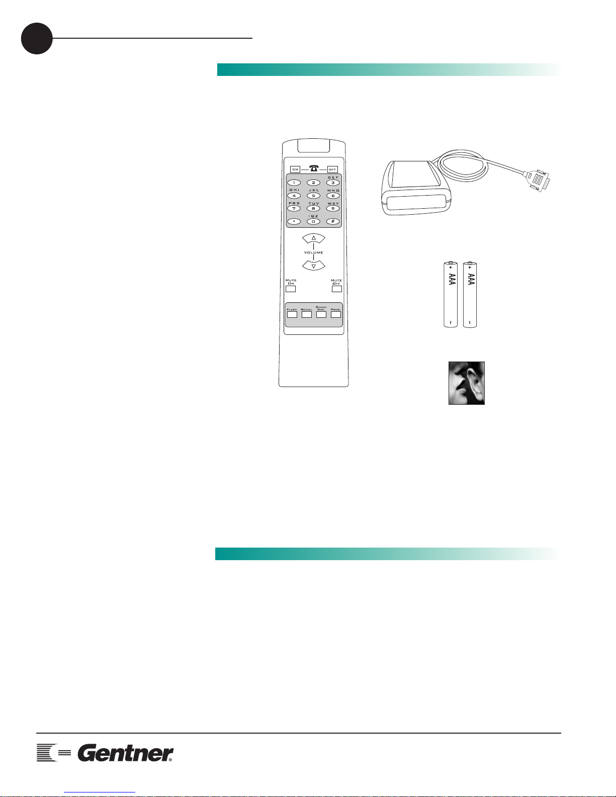
Please check that the following was received with your shipment.
Gentner Communications is not responsible for product damage incurred during
shipment. You must make claims directly with the carrier. Inspect your shipment
carefully for obvious signs of damage. If the shipment appears to be damaged,
retain the original boxes and packing material for inspection by the carrier. Contact
your carrier immediately.
Unpacking
Warranty
Instructions
Please register your Audio Perfect Infrared Remote System online by
visiting Gentner Technical Support on the World Wide Web at
www.gentner.com.
When your product is properly registered, Gentner Communications will
be able to serve you better should you require technical assistance or
desire to receive upgrades, new product information, etc.
Manual
Infrared
Remote
Transmitter
Infrared Remote Receiver
Batteries
ABC
Mute
Status
Audio Perfect® Infrared
Remote Control
AP REMOTE
Page 5
2
TECHNICAL SUPPORT: 1.800.283.5936 (USA) OR 1.801.974.3760
INSTALLATION
5
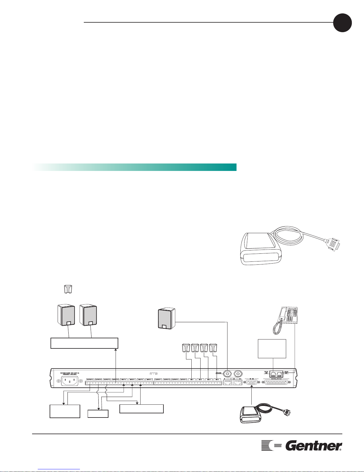
Installation is simple, only requiring plugging the AP IR Remote
Receiver into the RS232 connector located on the back of the
AP400 or AP800 unit.
Located on the AP IR Remote Receiver are two LEDs—STATUS and
MUTE. The STATUS LED will glow red when the receiver is
connected to the AP product indicating the system is ready for a
valid command. When a button is pressed, the STATUS LED flashes
rapidly indicating a command has been received.
When the MUTE ON button is pressed, the MUTE LED will blink on
and off indicating the system is in a muted state.
Installation
e
AP IR Remote Control Receiver
=
Microphone
5 W, 4 to 16 Ohm
Speaker Connection
External Power Amp
(Optional)
AP400
3241
Mute
Status
Analog
Telephone
Line
Telephon
Set
Video
CODEC
VCR
Tape Player
(Optional)
s
u
t
ta
S
e
t
u
M
AP IR Receiver
Page 6

INSTALLATION
TECHNICAL SUPPORT: 1.800.283.5936 (USA) OR 1.801.974.3760
6
Page 7

3
TECHNICAL SUPPORT: 1.800.283.5936 (USA) OR 1.801.974.3760
OPERATION • GETTING STARTED
7
Getting Started
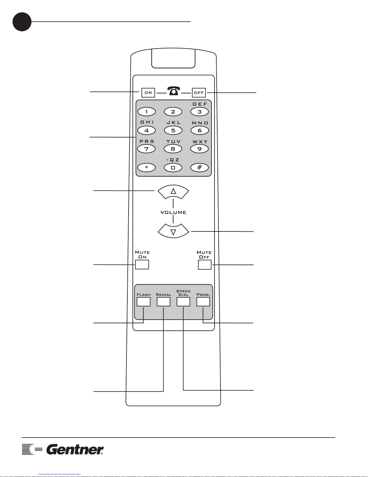
Once your remote is connected to your Audio Perfect system and the
STATUS LED is lit, it is time to start using your remote control. Operation
is easy and straight forward. Please consult the diagram on the following page to understand how each button on your remote works.
If you push a button and there is no response from the system, check to
ensure that both the AP device and the receiver are connected at the
same baud rate. See page 13 for instructions on how to program the
baud rate.
Operation
Page 8
OPERATION • REMOTE CONTROL BUTTONS
TECHNICAL SUPPORT: 1.800.283.5936 (USA) OR 1.801.974.3760
8
TELEPHONE ON
(green) button
Press to get a dial tone.
NUMBER buttons
Use these buttons to
dial telephone numbers
and to program
functions.
VOLUME UP button
Press to raise the
volume in the room.
MUTE ON button
Press to mute all
microphones in the
room (default). May be
programmed to mute
specific microphones
in the room.
TELEPHONE OFF
(red) button
Press to end a call.
ABC
VOLUME DOWN button
Press to lower the volume
in the room.
MUTE OFF button
Press to turn mute
function off.
FLASH button
Provides a hook flash
for accessing features
on your PBX. Please
consult your PBX
owner's manual for
specific instructions
regarding your
individual telephone
system.
REDIAL button
Press to dial the last
telephone number.
PROGRAM button
Press for two seconds
to enter PROGRAM
mode. See
Programming section,
page 13.
SPEED DIAL button
Press to dial telephone
numbers that have
been programmed into
the SPEED DIAL
function. See
Programming section,
page 14.
Page 9
TECHNICAL SUPPORT: 1.800.283.5936 (USA) OR 1.801.974.3760
OPERATION • REMOTE CONTROL BUTTONS
9
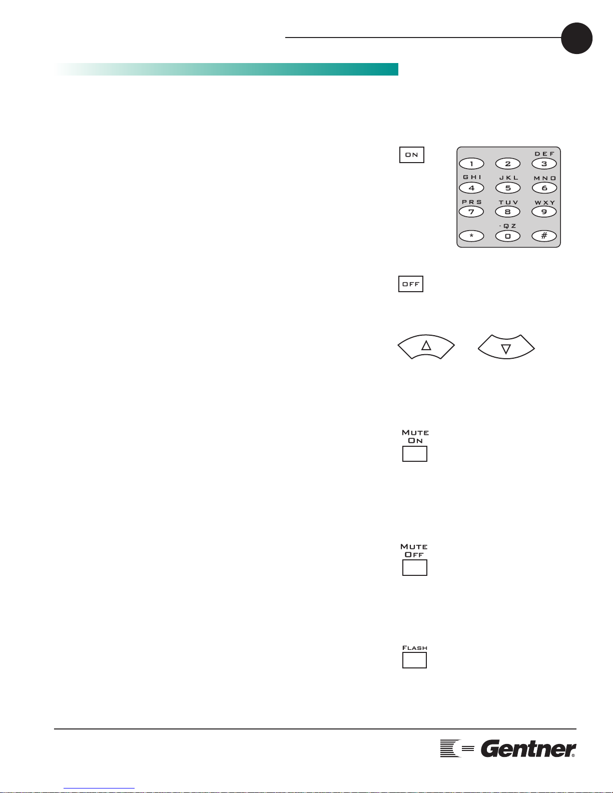
While within 25-40 feet of the receiver, point the remote control toward
the receiver and press the buttons to operate.
•To Place a Call
Press TELEPHONE ON (green) button.
Wait to hear dial tone.
Dial telephone number using dial pad. Or, press SPEED DIAL and the
location of the speed dial number.
•To End a Call
Press TELEPHONE OFF (red) button.
•To Adjust the Volume in the Room
Press VOLUME UP button to raise the volume.
Press VOLUME DOWN button to lower the volume.
•To Mute Microphones
Press MUTE ON button.
MUTE LED will flash on receiver when the MUTE function is active.
This function mutes all microphones in the room. To customize mute
feature, see Programming section, page 15.
•To Turn off Mute
Press MUTE OFF button.
MUTE LED on receiver will turn off when mute function is off.
•To Access Features from a PBX
Press FLASH button.
Please consult your PBX owner’s manual for specific requirements of
your individual phone system.
Remote Control
Buttons
ABC
Page 10

HOW TO PLACE A CALL
TECHNICAL SUPPORT: 1.800.283.5936 (USA) OR 1.801.974.3760
10
•To Redial the Last Telephone Number Dialed
Press REDIAL button.
•To Dial a Number Stored in Speed Dial
Press SPEED DIAL button. Select location (0-9) of speed dial number.
Note: In order for the Speed Dial function to work, a telephone
number must be programmed into the Number buttons. Please see
Programming section, page14.
•To Customize your AP IR Remote Control System
Follow instructions beginning on page 13 to customize your AP IR
Remote Control System to fit your specific conferencing needs.
Page 11

4
TECHNICAL SUPPORT: 1.800.283.5936 (USA) OR 1.801.974.3760
PROGRAMMING • BAUD RATE
11
Your AP Infrared Remote Control is defaulted to operate right out of the
box; however, it is easy to program should you require different specifications. Select from the options below and follow the instructions for
the desired function you wish to customize.
To Program Baud Rate
Press and hold the PROG button until both LEDs in the receiver flash.
Enter 22831 for 9600 bps (default)
Enter 22832 for 19200bps
Enter 22833 for 38400bps
Example:
To change the baud rate of the receiver to communicate at a rate of
19200 bps.
Programming
If you push a button and there
is no response from the
system, check to ensure that
both the AP device and the receiver are
connected at the same baud rate.
✍✍
Page 12
PROGRAMMING • SPEED DIAL AND TELEPHONE DEVICE
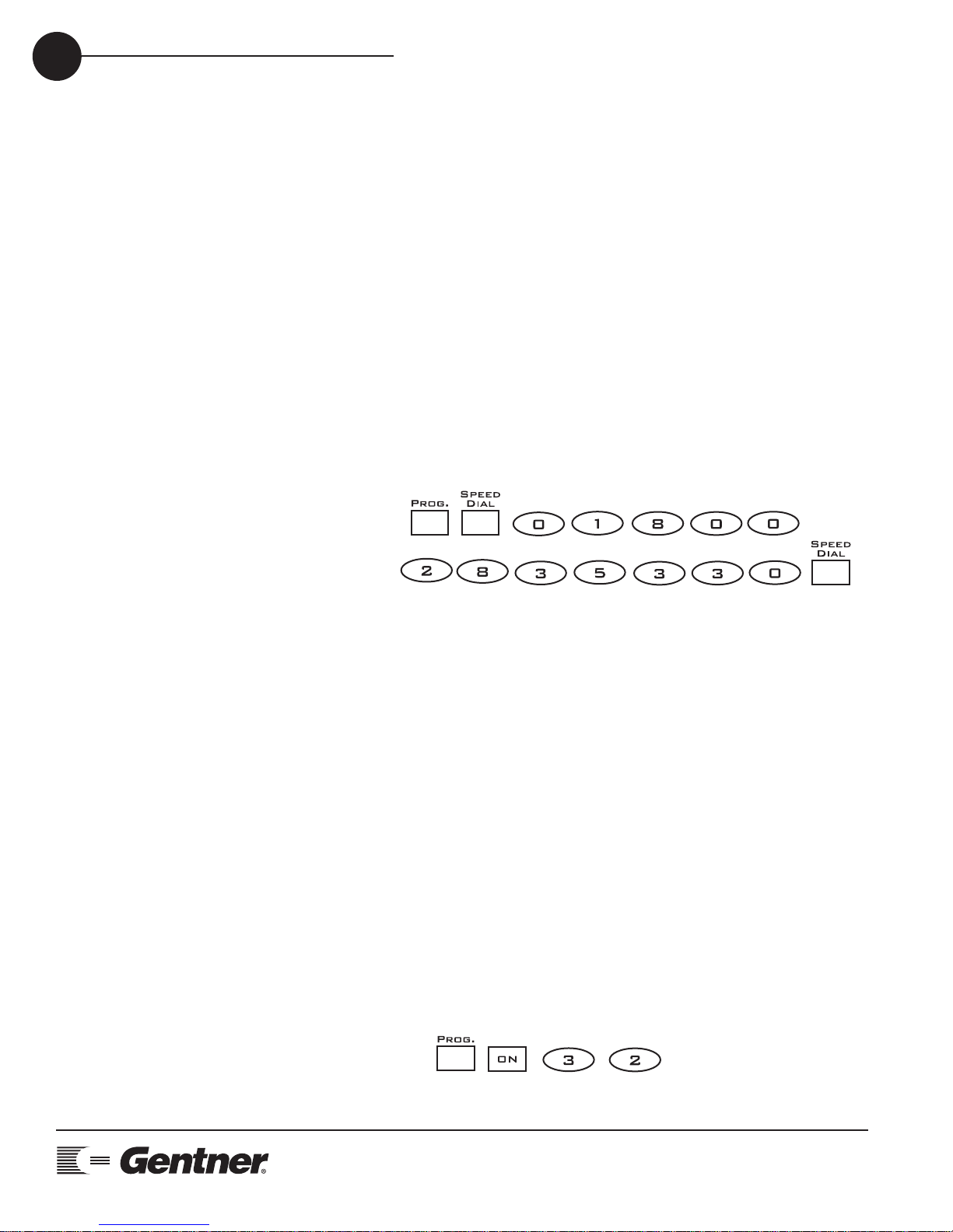
To Program Speed Dial
Press and hold the PROG. button until both LEDs in the receiver flash.
Press SPEED DIAL button.
Select a location (0-9) on the dial pad.
Enter the telephone number (use the VOLUME UP button for a 2
second pause).
Press SPEED DIAL button to store number.
To erase a preprogrammed location, press PROG., SPEED DIAL,
location (0-9), SPEED DIAL.
Example:
To store Gentner’s Technical Service number (1-800-283-5330) in
speed dial 0:
To Program Telephone Device
This sets the device that all telephone commands are sent to.
The default dial command begins with ** which dials any AP telephone
device. If more than one telephone device is connected to the system
this must be changed to address a specific device.
Press and hold the PROG. button until both LEDs in the receiver flash.
Press the ON button.
Enter Device Type (0=device connected to, 2=AP10, 3=AP400, *=all
telephone devices).
Enter Device ID (0-7, *=all units).
Example:
I want to control AP400 unit 2:
TECHNICAL SUPPORT: 1.800.283.5936 (USA) OR 1.801.974.3760
12
Location
Device Type
Device ID
Page 13
TECHNICAL SUPPORT: 1.800.283.5936 (USA) OR 1.801.974.3760
PROGRAMMING • MUTE
To Program Mute
There are ten locations for storing mute commands. All mute commands stored are performed when the MUTE ON or MUTEOFF button
is pressed.
Press and hold the PROG. button until both LEDs in the receiver flash.
Press the MUTE ON button
Select a location for muting (0-9).
Select the device type (0=device connected to, 1=AP800, 2=AP10,
3=AP400, *=all devices).
Select the device ID (0-7, *=all units).
Select channel for muting (*, 01-08, 11-15). See table to the right.
Select 4 for input or 6 for output.
To erase a programmed location press PROG., MUTE ON, location (0-9),
MUTE OFF.
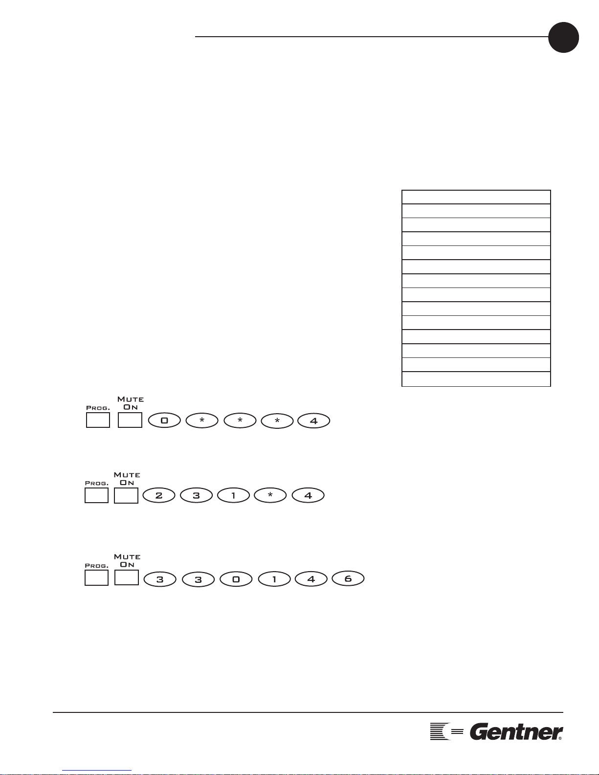
Examples:
Mute all mics on all units and store it in location 0 (default).
Mute all mics on AP400 #1 and store it in location 2.
Mute output D on AP400 # 0 and store it in location 3.
13
Location
Device Type Device ID Channel
Input/Output
* All Mics
01 Channel 1
02 Channel 2
03 Channel 3
04 Channel 4
05 Channel 5
06 Channel 6
07 Channel 7
08 Channel 8
11 Channel A
12 Channel B
13 Channel C
14 Channel D
15 Channel T
Location
Device Type
Location
Device Type
Device ID
Device ID
Channel
Input/Output
Channel
Input/Output
Page 14
PROGRAMMING • VOLUME
TECHNICAL SUPPORT: 1.800.283.5936 (USA) OR 1.801.974.3760
14
To Program Volume
There are ten locations for storing volume control commands. All volume control commands stored are performed when the VOLUME UP or
VOLUME DOWN button is pressed. To change the nominal level to
negative, enter an asterisk before the value.
Example: (*10) = -10 and (10) = +10.
Press and hold the PROG. button until both LEDs in the receiver flash.
Press the VOLUME UP button
Select a location for volume control (0-9).
Select the device type (0=device connected to, 1=AP800, 2=AP10,
3=AP400, *=all devices).
Select the device ID (0-7, *=all units).
Select channel for volume control (*, 01-08, 11-15) See table to the left:
Select 4 for input or 6 for output.
Select nominal level (*=negative nominal level, 00-20)
To erase a preprogrammed location, press PROG., VOLUME UP, location (0-9), VOLUME DOWN.
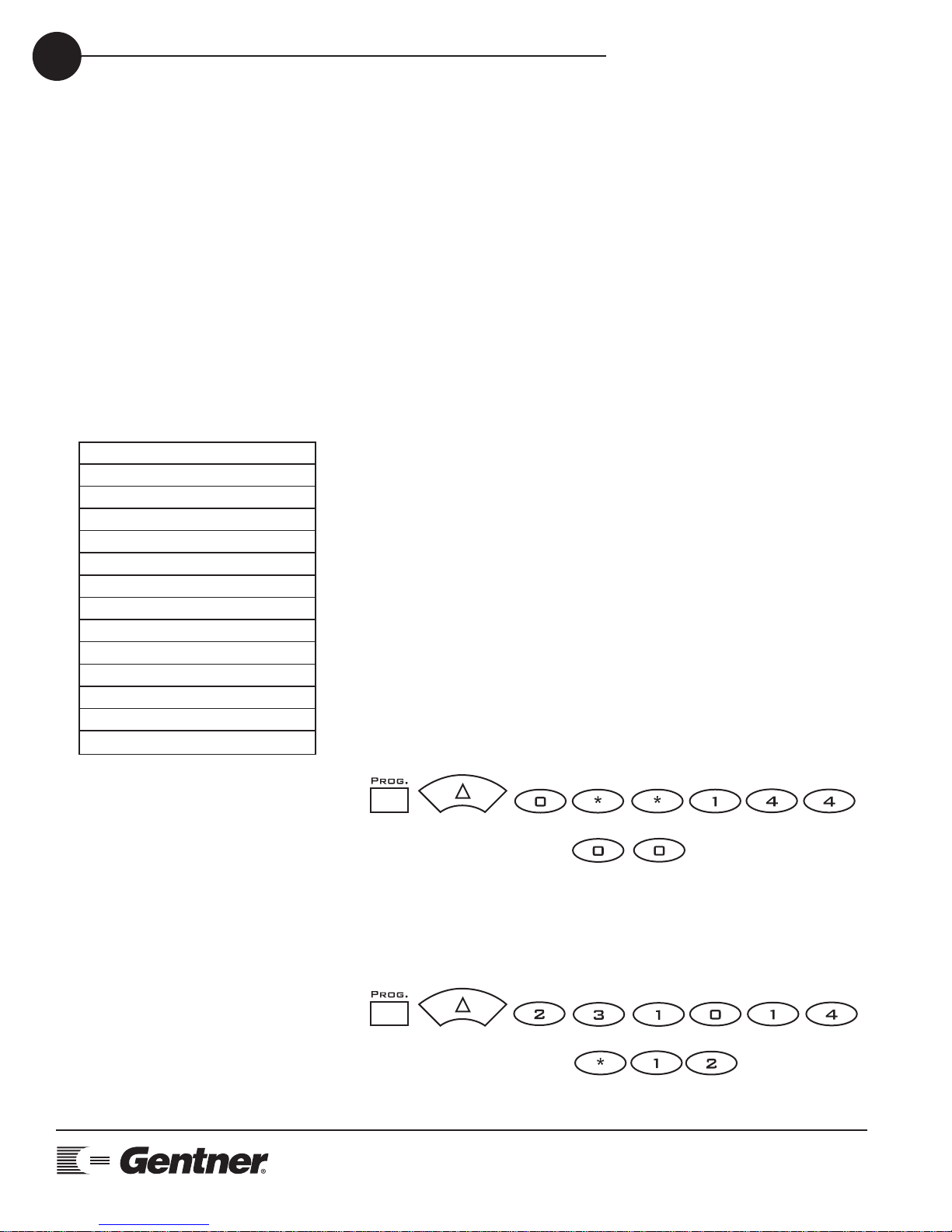
Examples:
Adjust volume of all output D with nominal level of 0 on all units and
store it in location 0 (default).
Adjust volume of Mic 1 with nominal level of -12 on AP400 # 1 and store
it in location 2.
* All Mics
01 Channel 1
02 Channel 2
03 Channel 3
04 Channel 4
05 Channel 5
06 Channel 6
07 Channel 7
08 Channel 8
11 Channel A
12 Channel B
13 Channel C
14 Channel D
15 Channel T
Location Device Type Device ID Channel Input/Output
Nominal Level
Location Device Type Device ID Channel Input/Output
Nominal Level
Page 15
TECHNICAL SUPPORT: 1.800.283.5936 (USA) OR 1.801.974.3760
PROGRAMMING • VOLUME RANGE/STEP SIZE
15
To Program Volume Range/Step Size
This is a global volume setting so all volume adjustments will have the
same range and step increment.
Press and hold the PROG. button until both LEDs in the receiver flash.
Press the VOLUME DOWN button.
Enter the 2 digit range of the volume (00-20).
Enter the step size of each volume press (0-9).
A range of 00 disables the adjustment of the volume from the remote
control buttons.
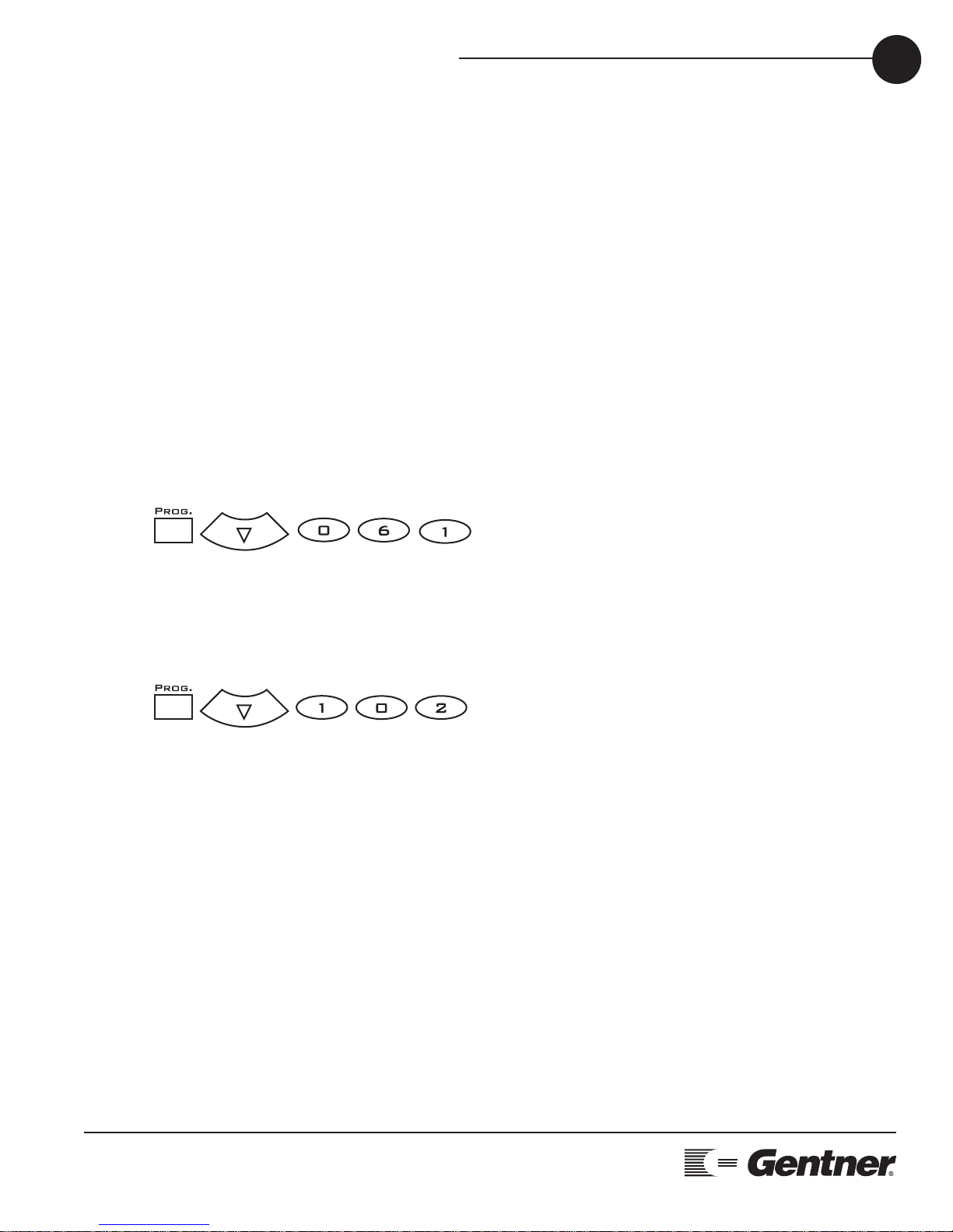
Examples:
If you want to change the volume range to ± 6 dB with 1 dB step
increments (default).
If you want to change the volume range to ± 10 dB with 2 dB step
increments.
Range
Range
Step
Range
Range
Step
Page 16

PROGRAMMING • HOOK FLASH AND RESET
TECHNICAL SUPPORT: 1.800.283.5936 (USA) OR 1.801.974.3760
16
To Program Hook Flash (AP400 only)
Press and hold the PROG. button until both LEDs in the receiver flash.
Press the FLASH button.
Press 1 (for 50 msec) or 2 (for 500 msec).
This is stored in the AP400 and not in the AP IR Remote.
Example:
If you want to change the hook flash duration from default (500 msec)
to 50 msec
To Reset the AP IR Remote back to Default
Press and hold the PROG. button until both LEDs in the receiver flash.
Press ****.
Example:
If you want to reset the AP IR Remote back to default.
Page 17

5
TECHNICAL SUPPORT: 1.800.283.5936 (USA) OR 1.801.974.3760
APPENDICES • APPENDIX A: SPECIFICATIONS
17
Transmitter
Dimensions: 7 5/8"L x 2 3/16"W x 1/2"H
Battery Type: 2 AAA
Battery Life: Approximately 1 year
Receiver
Dimensions: 5"L x 2 3/4"W x 1"H
Power: Powered by the AP system
Cable Length: 6'
System
Range: 25-40 feet from transmitter to receiver
Angle of
Acceptance: 90
°
- 120
°
Operating
Temperature: 0
°
- 50°C, 32°- 122°F
Appendices
Specifications
Page 18

APPENDICES APPENDIX B: WARRANTY
TECHNICAL SUPPORT: 1.800.283.5936 (USA) OR 1.801.974.3760
18
Gentner Communications Corporation (Manufacturer) warrants that this
product is free of defects in both materials and workmanship. Should
any part of this equipment be defective, the Manufacturer agrees, at its
option, to:
A. Repair or replace any defective part free of charge (except transportation charges) for a period of one year from the date of the original
purchase, provided the owner returns the equipment to the
Manufacturer at the address set forth below. No charge will be made for
parts or labor during this period;
B. Furnish replacement for any defective parts in the equipment for a
period of one year from the date of original purchase. Replacement
parts shall be furnished without charge, except labor and transportation.
This Warranty excludes assembled products not manufactured by the
Manufacturer whether or not they are incorporated in a Manufacturer
product or sold under a Manufacturer part or model number.
THIS WARRANTY IS VOID IF:
A. The equipment has been damaged by negligence, accident, act of
God, or mishandling, or has not been operated in accordance with the
procedures described in the operating and technical instructions; or,
B. The equipment has been altered or repaired by other than the
Manufacturer or an authorized service representative of the
Manufacturer; or,
C. Adaptations or accessories other than those manufactured or provided by the Manufacturer have been made or attached to the equipment which, in the determination of the Manufacturer, shall have affected the performance, safety or reliability of the equipment; or,
D. The equipment’s original serial number has been modified or
removed.
NO OTHER WARRANTY, EXPRESS OR IMPLIED, INCLUDING WARRANTY OF MERCHANTABILITY OR FITNESS FOR ANY PARTICULAR USE,
APPLIES TO THE EQUIPMENT, nor is any person or company authorized to assume any warranty for the Manufacturer or any other liability in
connection with the sale of the Manufacturer's products.
Manufacturer does not assume any responsibility for consequential
damages, expenses, or loss of revenue or property, inconvenience, or
Warranty
Page 19

TECHNICAL SUPPORT: 1.800.283.5936 (USA) OR 1.801.974.3760
APPENDICES APPENDIX C: COMPLIANCE
19
interruption in operation experienced by the customer due to a malfunction in the purchased equipment. No warranty service performed
on any product shall extend the applicable warranty period.
In case of unsatisfactory operation, the purchaser shall promptly notify
the Manufacturer at the address set forth below in writing, giving full
particulars as to the defects or unsatisfactory operation. Upon receipt of
such notice, the Manufacturer will give instructions respecting the shipment of the equipment, or such other matters as it elects to honor this
warranty as above provided. This warranty does not cover damage to
the equipment during shipping and the Manufacturer assumes no
responsibility for such damage. All shipping costs shall be paid by the
customer.
This warranty extends only to the original purchaser and is not assignable or transferable.
Gentner Communications Corporation
1825 Research Way, Salt Lake City, Utah 84119
FCC Compliance
FCC Part 15 Compliance
This equipment has been tested and found to comply with the limits for
a Class B digital device, pursuant to Part 15 of the FCC rules. These limits are designed to provide reasonable protection against harmful interference when the equipment is operated in a commercial environment.
This equipment generates, uses, and can radiate radio frequency energy and, if not installed and used in accordance with the instruction manual, may cause harmful interference to radio communications.
Operation of this equipment in a residential area is likely to cause harmful interference, in which case the user will be required to correct the
interference at his/her own expense.
Changes or modifications not expressly approved by Gentner
Communications Corporation could void the user’s authority to operate
the equipment.
 Loading...