

Page 1
ST AND HS SERIES
UL 1971 COMPLIANT
CAN/ULC S526-M87 Compliant
VISIBLE AND AUDIBLE/VISIBLE SIGNALING APPLIANCES
I. INTRODUCTION
The Gentex Model ST/HS, strobe and horn/strobe, is a high quality visible (ST) or audible/visible (HS) signaling appliance. The high intensity strobe
utilizes a Xenon flash tube that generates a high-intensity flash visible from all angles. This appliance is intended to provide a visible or audible/visible,
depending on the model, notification signal for the purpose of life safety and property protection. This appliance is ideal for hotels, apartments,
hospitals, rest homes or wherever dependable alarms are required. The strobe is listed in compliance with UL 1971, Signaling Appliances for the
Hearing Impaired and CAN/ULC S526-M87 Visible Signal Devices for Fire Alarm Systems (15/75 Cd model is additionally listed in compliance with
UL 1638).
II. LOCATION
This appliance is intended for use in Fire Alarm Systems and is to be installed in accordance with this manual, the recommendation of the local
authorities having jurisdiction, and other NFPA documents that provide standards on notification appliances for protective signaling systems. The
ST/HS is intended for indoor installations only. This appliance is not weatherproof for outdoor or drip proof applications.
Wall mounted strobe and horn/strobe appliances shall have their entire lens at heights above the finished floor of not less than 80 in. (2m) and not
greater than 96 in. (2.4m)**. Spacing shall be in accordance with Table A. If a room configuration is not square, the room size that will entirely
encompass the room or subdivide the room into multiple squares shall be used.
Wall mounted horn only appliances shall have their tops above the finished floors at heights of not less than 90 in. (2.30m) and below the finished
ceilings at heights of not less than 6 in. (152mm). Different mounting heights shall be permitted by the AHJ provided the sound pressure level
requirements of NFPA 72 are met.
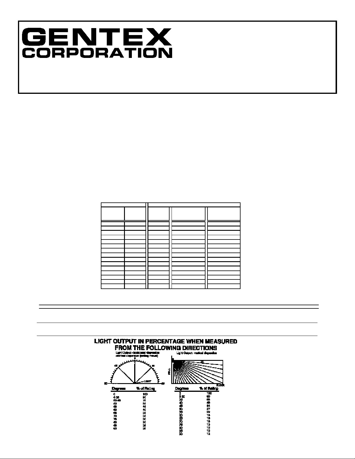
Table A
Maximum Room Size Minimum Required Light Output (Effective Intensity, Cd)
Meters Feet One Light Room (Located on Room (One Light
6.10 x 6.10 20 x 20 15 NA NA
8.53 x 8.53 28 x 28 30 Unknown Unknown
9.14 x 9.14 30 x 30 34 15 NA
12.2 x 12.2 40 x 40 60 30 15
13.7 x 13.7 45 x 45 75 Unknown Unknown
15.2 x 15.2 50 x 50 94 6 30
16.5 x 16.5 54 x 54 110 Unknown Unknown
18.3 x 18.3 60 x 60 135 95 30
21.3 x 21.3 70 x 70 184 95 60
24.4 x 24.4 80 x 80 240 135 60
27.4 x 27.4 90 x 90 304 185 95
30.5 x 30.5 100 x 100 375 240 95
33.5 x 33.5 110 x 110 455 240 135
36.6 x 36.6 120 x 120 540 305 135
39.6 x 39.6 130 x 130 635 375 185
per Room Opposite Walls) per Wall)
Two Lights per Four Lights per
NA = Not Allowable
**Effective Intensity Requirements for Sleeping Areas
Visible Notification Appliance
Distance from Ceiling to Top of Lens Intensity
greater than or equal to 24" 110cd
less than 24" 177cd
Pg. 1
Page 2
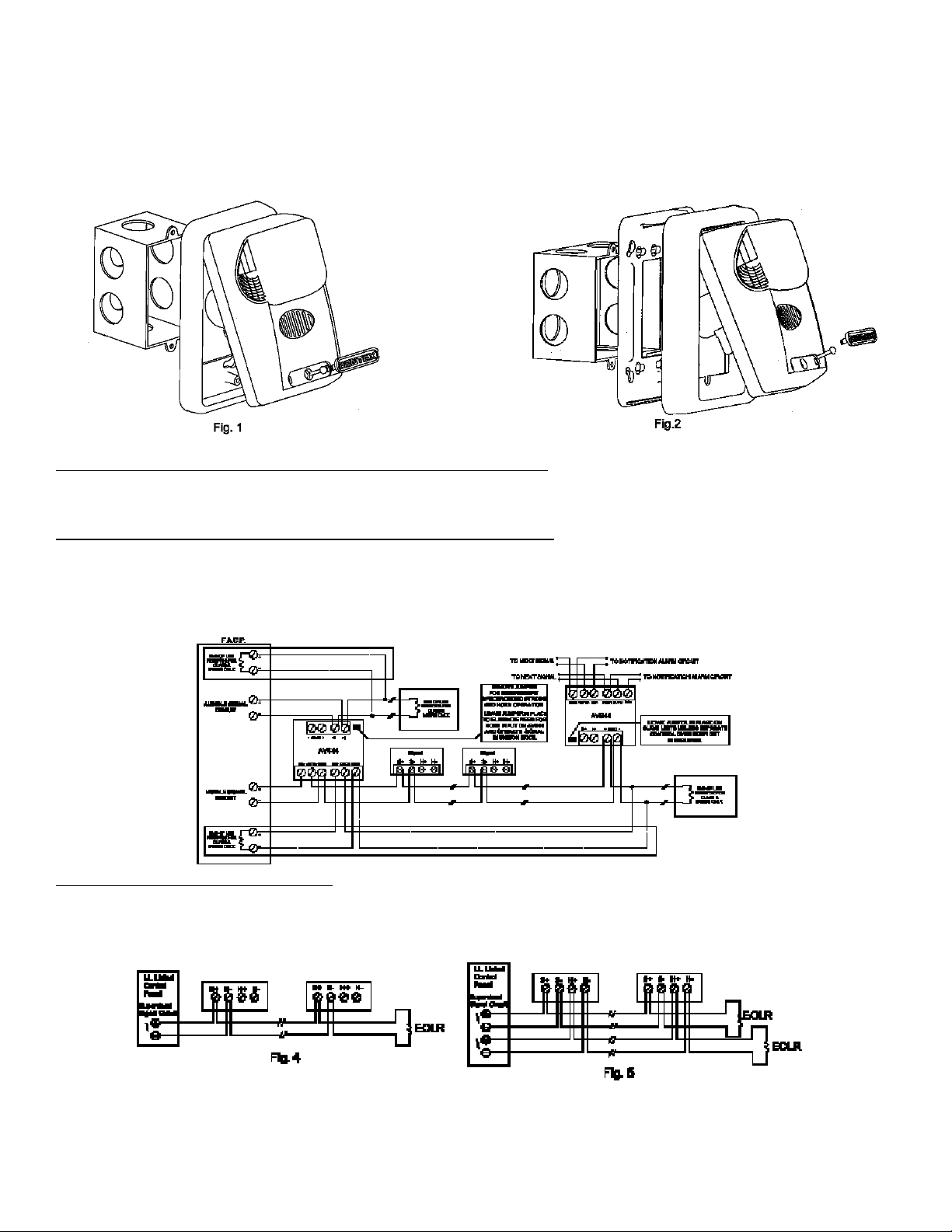
III. MOUNTING, ROUGH-IN BOX AND RUN WIRING
This unit is designed for mounting to most single gang boxes (Fig.1). 4" square outlet boxes, 2-gang masonry boxes or non-metallic 2-gang switch
boxes with a minimum depth of 1½" may also be used with the 4" mounting plate (Fig.2). Conduit entrance to boxes should be selected to insure
sufficient wiring clearance.
1. Mount a box for each remote signaling appliance.
2. Run a minimum 18 gauge insulated 2 or more conductor cable.
NOTE: All strobes are designed to flash as specified with continuous applied voltage. This appliance is not recommended for use on coded or
pulsing signaling circuits. However, use of the AVS44 is permitted to synchronize and/or mute the strobe and horn.
IV. WIRING
Fig. 3: Wiring diagram for independent synchronized strobes and horn.
Using this method you may:
1. Use only two wires to synchronize the temporal horn and strobe with the ability to mute the horn (J1 and J2 in place on the HS).
2. Mute the horn only when the temporal horn option has been selected.
Wiring diagram for synchronized parallel (unison) horn/strobe operation.
Using this method you may:
1. Use only two wires to synchronize the temporal horn and strobe without the ability to mute the horn (J1 and J2 in place on the HS).
2. Choose either temporal or continuous horn with the temporal horn synchronized (Fig.6).
3. Also wire the control module (AVS44) to only the strobe input power terminals, set the horn to continuous mode (Fig.6) and power it from a march
time source. NOTE: For this option, J1 and J2 on the HS (Fig.6) must be removed to isolate power to the audible and visible portion of the circuit.
Fig. 3
Fig. 4 and Fig. 5: Conventional Method
You may connect both the strobe and the horn directly from a source of rated power without the use of a control module. However, the horns and
strobe lights will NOT be synchronized. Leave jumpers J1 and J2 in place on the HS (Fig.6) to power both the audible and visible from a single pair of
power wires (Fig.4). If you wish to power the horn and strobe from independent sources of power, remove J1 and J2 on the HS (Fig.6) and connect
power to the appropriate terminals (Fig.5).
CAUTION: When using only a single pair of terminals to power the strobe and horn (J1 and J2 in), the in/out
wiring must be under the same terminal. Failure to do so may result in damage to your signal.
NOTE: INSTALLATION IN CANADA - All Canadian installations should be in accordance with the Canadian
Standard for the Installation of Fire Alarm Systems - CAN/ULC S524-01 and the Canadian Electrical Code, Part 1.
Pg. 2
Page 3

HORN
VOLTAGE
16VDC
24VDC
33VDC
16VFWR
24VFWR
33VFWR
MAX. WIRE
DISTANCE =
(IN FEET)
Includes wire to and from appliance. CAUTION: Applies only to regulated
supplies. Assumes all appliances are at the end of wire run (worst case).
HORN RATINGS
dBA @
10Ft. Per
UL464
76-88 90 19 76-88 92 26 76-88 95 34 76-88 90 - 35
76-88 92 - 43
76-88 95 - 49
(PANEL VOLTAGE-APPLIANCE MIN. VOLT) X WIRE CONDUCTIVITY
{
WIRE CONDUCTIVITY
18AWG 60
16AWG 95
14AWG 153
12AWG 244
dBA @
10Ft.
Anechoic
TOTAL CURRENT DRAW
DC(mA) FWR(mA)
}
STROBE CURRENT RATING
DC (mA) FWR (mA)
Candela Voltage Inrush Peak Operating Inrush Peak Operating
16 162 118 63 174 189 79
15 24 178 145 42 182 181 61
33 178 172 34 182 189 57
16 212 140 99 240 188 119
30 & 15/75 24 248 144 66 256 187 84
33 256 179 52 260 192 72
16 310 198 134 310 286 169
60 24 314 218 84 322 291 110
33 322 274 61 330 295 86
16 320 216 161 312 307 209
75 24 316 243 100 324 285 139
33 336 289 75 328 267 108
16 396 228 193 392 292 247
110 24 396 247 118 392 304 160
33 400 286 86 408 308 123
Note: Units have been tested to OOC, 49OC and 93% humidity and are rated 20-30vdc/vFWR -20%, +10%, per
CAN/ULC S526-M87. The 15/75 model is rated 15cd per UL1971 and CAN/ULC S526-M87. Units are rated
16-33vdc/vFWR absolute per UL464 and UL1971.
V. CHECKOUT AND TROUBLESHOOTING
1. Supply power to the system control panel. The auxiliary signaling appliances in the system should not be activated.
2. If the signal is activated:
· Check all smoke and fire detectors in the system to make sure they have not been activated.
· Check all wiring connections to make sure the signal detection circuits are not reversed or shorted together. Check wire color codes and traces.
· Verify that the jumpers are properly set on both the control module and signal appliance. If the jumper on the AVS44 is as shown in Fig. 3, the
horns will not produce any sound unless there is an input to the H+ and H- terminals on the control module.
3. To test the signal appliances, trip the auxiliary panel or activate the alarm circuit at the main control panel or activate one of the fire detection units in
the system. All auxiliary signals should be activated.
4. An operational test on this product should be conducted in accordance with National Standards or at a minimum annually and more often if dictated
by local and state codes or authorities having jurisdiction.
Pg. 3
Page 4

NOTE: These testing procedures and troubleshooting instructions are generalized. Please refer to the system control panel operating
instructions for proper operation of the panel and fire detection system.
SIGNALING APPLIANCE LIMITATION:
Your strobe and horn/strobe meet or exceed the current audibility requirements of Underwriters Laboratories. However, if the appliance is located outside a bedroom it may not wake up a sound sleeper, especially if the room door is closed or only partially open.
WARNING
THIS APPLIANCE WILL NOT OPERATE WITHOUT ELECTRICAL POWER. AS FIRES FREQUENTLY CAUSE POWER INTERRUPTIONS,
GENTEX SUGGESTS YOU DISCUSS FURTHER SAFEGUARDS WITH YOUR LOCAL FIRE PROTECTION SPECIALIST.
VI. TO RETURN AN APPLIANCE:
Should you experience problems with your appliance, proceed as follows:
1. Turn off electrical power to the auxiliary alarm circuit.
2. Unscrew the unit from the electrical box.
3. Disconnect the unit from the field wiring. Reconnect the two positive supply wires and the two negative supply wires of the auxiliary alarm circuit to
maintain power to the other alarm appliances in the system.
4. Carefully pack the defective unit (the manufacturer cannot be responsible for consequential damage due to shipping or mis-handling). Include your
return address and complete details as to the nature of the difficulties being experienced and date of installation.
5. Return to: Gentex Corporation, 10985 Chicago Dr., Zeeland MI 49464. Prior to returning, call the Gentex field service dept. @ 1-800-436-8391 for
a RMA number.
For a period of 24 months from the date of purchase or a maximum of 30 months from the date of manufacture, Gentex warrants to you the original purchaser that your appliance will be free from
defects in workmanship, materials and construction under normal use and service. If a defect in workmanship, materials and construction should cause your appliance to become inoperative within the
warranty period, Gentex will repair your appliance or furnish you with a new or rebuilt appliance without charge to you except for postage required to return the appliance to us. Gentex will not reimburse you for repairs or replacement parts provided by other parties. Your repaired or replacement appliance will be returned to you free of charge and it will be covered under the warranty for the balance of the warranty period.
The warranty is void if our inspection of your appliance shows that the damage or failure was caused by abuse, misuse, abnormal usage, faulty installation, improper maintenance or repairs other than
those performed by us.
ANY WARRANTIES IMPLIED UNDER ANY STATE LAW INCLUDING IMPLIED WARRANTIES OF MERCHANTABILITY OR FITNESS FOR A PARTICULAR PURPOSE APPLY ONLY FOR THE
WARRANTY PERIOD SPECIFIED ABOVE. PLEASE NOTE THAT SOME STATES DO NOT ALLOW LIMITATION ON HOW LONG AN IMPLIED WARRANTY LASTS. SO THE ABOVE
LIMITATION MAY NOT APPLY TO YOU. GENTEX WILL NOT BE LIABLE FOR ANY LOSS, DAMAGE, INCIDENTAL OR CONSEQUENTIAL DAMAGES OF ANY KIND ARISING IN
CONNECTION WITH THE SALE, USE OR REPAIR OF THIS APPLIANCE. THE MAXIMUM LIABILITY OF GENTEX SHALL NOT IN ANY CASE EXCEED THE PURCHASE PRICE PAID BY YOU
FOR THE APPLIANCE. PLEASE NOTE THAT SOME STATES DO NOT ALLOW THE EXCLUSION OR LIMITATION OF INCIDENTAL OR CONSEQUENTIAL DAMAGES, SO THE ABOVE
LIMITATION OR EXCLUSION MAY NOT APPLY TO YOU.
If a defect in workmanship, materials or construction should cause your appliance to become inoperable within the warranty period, you must return the appliance to Gentex postage prepaid. You must
prove to the satisfaction of Gentex the date of purchase of your appliance. Warranty service may only be performed by Gentex personnel at Gentex's facilities in Zeeland, Michigan. You must also
pack the appliance to minimize the risk of it being damaged in transit. You must also enclose a return address. Appliances returned for warranty service should be sent to: Gentex Corporation, 10985
Chicago Dr., Zeeland MI 49464. If we receive an appliance in a damaged condition as the result of shipping, we will notify you and you must seek a claim with the shipper.
THIS WARRANTY GIVES YOU SPECIFIC LEGAL RIGHTS AND YOU MAY ALSO HAVE OTHER RIGHTS WHICH VARY FROM STATE TO STATE.
Gentex Corporation
10985 Chicago Dr., Zeeland MI 49464
Phone: 800-436-8391
LIMITED WARRANTY
550-144-13
6/1/97
Pg. 4
 Loading...