

Page 1
WARRANTY
First Year Warranty
The Gentec-EO thermal power and energy detectors carry a one-year warranty (from date of shipment)
against material and /or workmanship defects when used under normal operating conditions. The
warranty does not cover recalibration or damages related to misuse.
Gentec-EO will repair or replace at its option any wattmeter or joulemeter which proves to be defective
during the warranty period, except in the case of product misuse.
Any unauthorized alteration or repair of the product is also not covered by the warranty.
The manufacturer is not liable for consequential damages of any kind.
In the case of a malfunction, contact the local Gentec-EO distributor or nearest Gentec-EO office to
obtain a return authorization number. Return the material to the address below.
All customers:
Gentec-EO, Inc.
445 St-Jean-Baptiste, Suite 160
Quebec, QC, G2E 5N7
Canada
Tel: (418) 651-8003
Fax: (418) 651-1174
Email: service@gentec-eo.com
Web: www.gentec-eo.com
Lifetime Warranty
Gentec-EO will warranty any thermal power and energy detector head for its lifetime as long as it has
been returned for recalibration annually from the date of shipment. This warranty includes parts and labor
for all routine repairs including normal wear under normal operating conditions.
Gentec-EO will inspect and repair the detector during the annual recalibration. Exceptions to repair at
other times will be at Gentec-EO’s option.
Not included is the cost of annual recalibration or consequential damages from using the detector.
The only condition is that the detector head must not have been subject to unauthorized service or
damaged by misuse. Misuse would include, but is not limited to; laser exposure outside Gentec-EO’s
published specifications, physical damage due to improper handling, and exposure to hostile
environments. Hostile environments would include, but are not limited to excessive temperature,
vibration, humidity (>80%), or surface contaminants; exposure to flame, solvents or water; and connection
to improper electrical voltage.
Page 2

Revision 2.1
TABLE OF CONTENTS
TABLE OF CONTENTS ......................................................................................2
LIST OF ILLUSTRATIONS .................................................................................3
1 Warranty 4
1.1 . First Year Warranty 4
1.2 . Lifetime Warranty 4
2 GENERAL INFORMATION 5
2.1 . INTRODUCTION 5
2.2 . UM-B SERIES “SMART INTERFACE” CONNECTOR 6
2.3 . UM-B SERIES SPECIFICATIONS 8
3 OPERATING INSTRUCTIONS 9
3.1 . When used with a compatible monitor 9
3.1.1 .. General Instructions 9
3.2 . Working at other wavelengths than 1.064µm 10
3.3 . When using an oscilloscope: 11
3.3.1 .. General Instructions 11
3.3.2 .. Working at other wavelengths than 1.064µm 13
2
4 DAMAGE TO THE OPTICAL ABSORBER MATERIALS 14
OPTIONAL ACCESSORIES 16
4.1 . Other Accessories: 16
5 APPENDIX A 17
5.1 . Recycling and separation procedure for WEEE directive 2002/96/EC. 17
5.2 . Separation: 17
5.3 . DECLARATION OF CONFORMITY 18
UM-B Series Instruction Manual Gentec Electro-Optics Inc. All rights reserved
Page 3

Revision 2.1
LIST OF ILLUSTRATIONS
Fig. 1-1 DB-15 “Smart Interface” connector Pin-out .............................................................. 7
Fig. 2-1 UM-B wattmeter with monitor ..................................................................................... 9
Fig. 2-1 UM-B wattmeter with oscilloscope ........................................................................... 11
3
UM-B Series Instruction Manual Gentec Electro-Optics Inc. All rights reserved
Page 4

4
Revision 2.1
1 Warranty
1.1 First Year Warranty
The Gentec-EO thermal power and energy detectors carry a one-year warranty (from date of shipment)
against material and /or workmanship defects when used under normal operating conditions. The
warranty does not cover recalibration or damages related to misuse.
Gentec-EO will repair or replace at its option any wattmeter or joulemeter which proves to be defective
during the warranty period, except in the case of product misuse.
Any unauthorized alteration or repair of the product is also not covered by the warranty.
The manufacturer is not liable for consequential damages of any kind.
In the case of a malfunction, contact the local Gentec-EO distributor or nearest Gentec-EO office to
obtain a return authorization number. Return the material to the appropriate address below.
Contacting Gentec Electro-Optics Inc.
To help us answer your calls more efficiently please have the model number of the detector you are
using ready before calling Customer Support.
All customers:
Gentec-EO, Inc.
445 St-Jean-Baptiste, Suite 160
Quebec, QC, G2E 5N7
Canada
Tel: (418) 651-8003
Fax: (418) 651-1174
Email: [email protected]
Web: www.gentec-eo.com
1.2 Lifetime Warranty
Gentec-EO will warranty any thermal power and energy detector head for its lifetime as long as it has
been returned for recalibration annually from the date of shipment. This warranty includes parts and labor
for all routine repairs including normal wear under normal operating conditions.
Gentec-EO will inspect and repair the detector during the annual recalibration. Exceptions to repair at
other times will be at Gentec-EO’s option.
Not included is the cost of annual recalibration or consequential damages from using the detector.
The only condition is that the detector head must not have been subject to unauthorized service or
damaged by misuse. Misuse would include, but is not limited to, laser exposure outside Gentec-EO’s
published specifications, physical damage due to improper handling, and exposure to hostile
environments. Hostile environments would include, but are not limited to excessive temperature,
vibration, humidity, or surface contaminants; exposure to flame, solvents or water; and connection to
improper electrical voltage.
UM-B Series Instruction Manual Gentec Electro-Optics Inc. All rights reserved
Page 5

2 GENERAL INFORMATION
2.1 INTRODUCTION
The Gentec-EO UM-B Series is a robust line of high performance and high accuracy pyroelectric
wattmeters. Each unit is built for durability, compactness and ease of operation.
The UM-B optical absorber exhibits high damage thresholds and very low reflection.
The UM-B Series benefits from the use of a DB-15 male, “Smart Interface” connector, containing
an EEPROM (Erasable Electrical Programmable Read-Only Memory) programmed with the
calibration sensitivity, the spectral correction factors at different wavelengths and other data
related to the specific UM-B Series wattmeter head. This connector allows the monitor to
automatically adjust its setting to those of the wattmeter being connected.
The DA versions of the UM-B series, to be used with the APM(APM (D) with DB-15 connector)
do not have the “Smart Interface” function. These wattmeters cannot be used with a monitor.
They must be used with an APM, and an oscilloscope or an OEM acquisition system.
Every UM-B Series wattmeter features high intrinsic responsivity and high insensitivity to
electromagnetic interference.
The UM-B Series also offers an exceptionally wide dynamic range and allows power
measurements from UV to the far IR.
UM-B Series wattmeters are designed for user-friendly power measurement of CW lasers using a
monitor.
UM-B Series wattmeters require no external power source1. They can also be used with a 1 M
input impedance oscilloscope1 (or fast chart recorder). The calibrated V/W sensitivity is
documented in the calibration certificate of each unit. The spectral correction of this sensitivity is
also documented in the “Personal wavelength correction” certificate.
Each probe also includes a standard optical stand and post.
1
An APM is required.
5
Revision 2.1
UM-B Series Instruction Manual Gentec Electro-Optics Inc. All rights reserved
Page 6

6
Revision 2.1
2.2 UM-B SERIES “SMART INTERFACE” CONNECTOR 2
The DB-15 male “Smart Interface” connector contains an EEPROM (Erasable Electrical Programmable
Read-Only Memory) programmed with the calibration sensitivity and other data related to the specific UM-
B wattmeter in use. Faster set-ups are obtained because the monitor automatically adjusts to the
characteristics of the wattmeter, when the “Smart Interface” is connected to the monitor.
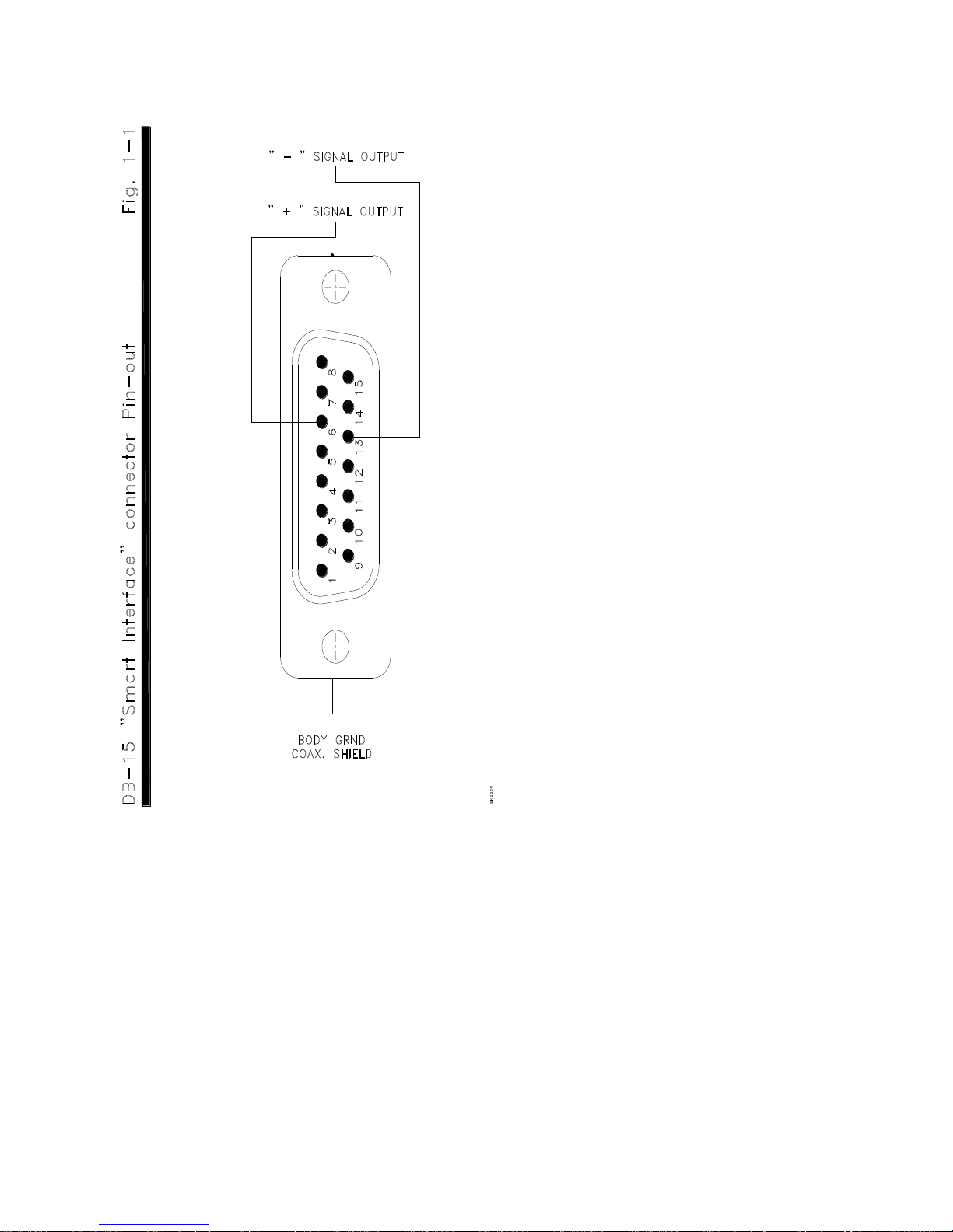
The DB-15 “Smart Interface” connector pin-out is (see Fig. 1-1):
1- USED BY MONITORS
2- " " " "
3- " " " "
4- " " " "
5- " " " "
6- “+” SIGNAL OUTPUT
7- ‘’-’’ SUPPLY VOLTAGE UM-B ONLY
8- USED BY MONITORS
9- ‘’+’’ SUPPLY VOLTAGE UM-B ONLY
10- USED BY MONITORS
11- " " " "
12- " " " "
13- “-“ SIGNAL OUTPUT
14- USED BY MONITORS
15- " " " "
SHELL- COAX. SHIELD / BODY GRND
NOTE : Verify with Gentec-EO for supply voltage requirements.
UM-B Series Instruction Manual Gentec Electro-Optics Inc. All rights reserved
Page 7
Revision 2.1
7
UM-B Series Instruction Manual Gentec Electro-Optics Inc. All rights reserved
Page 8

Revision 2.1
UM9B-BL-D0
Monitor Compatibility
MAESTRO & M-LINK
(with latest firmware version only)
NIG
202024 (without stand)
202111 (with stand)
Effective Aperture Diameter
Ø9 mm
Sensor
Pyroelectric
Absorber
BL
Spectral Range
0.1 - 20 µm
Calibrated Spectral Rangea 0.25 – 2.5 µm
Max. Average Power
With MAESTRO : 20 mW
With M-LINK : 25 mW
Max. Average Power Density
50 mW/cm2
Power Noise Level (RMS)
300 nW
Optical Chopper Frequency
10 ± 1 Hz
Typical Rise time (0-95%)
< 0.2s
Typical sensitivity
120 V/W
Calibration Uncertainty
@ 1.064 µm
± 4.0 %
Dimensions (H x W x D, in mm)
Ø38.1 x 26.2
Weight
91 g
2.3 UM-B SERIES SPECIFICATIONS
The following specifications are based on a one-year calibration cycle, an operating temperature of 15 to
28ºC and a relative humidity not exceeding 80% and a storage temperature from 5 to 45 ºC with relative
humidity not exceeding 80%.
8
a
The calibrations at 2.1 to 2.5 µm and 10.6 µm are on special request only.
Specifications subject to change without notice.
UM-B Series Instruction Manual Gentec Electro-Optics Inc. All rights reserved
Page 9
Revision 2.1
3 OPERATING INSTRUCTIONS
3.1 When used with a compatible monitor
or
9
Refer to the user manual of each monitor for further information.
3.1.1 General Instructions
1- Place the wattmeter on its optical stand (Must use a delrin post).
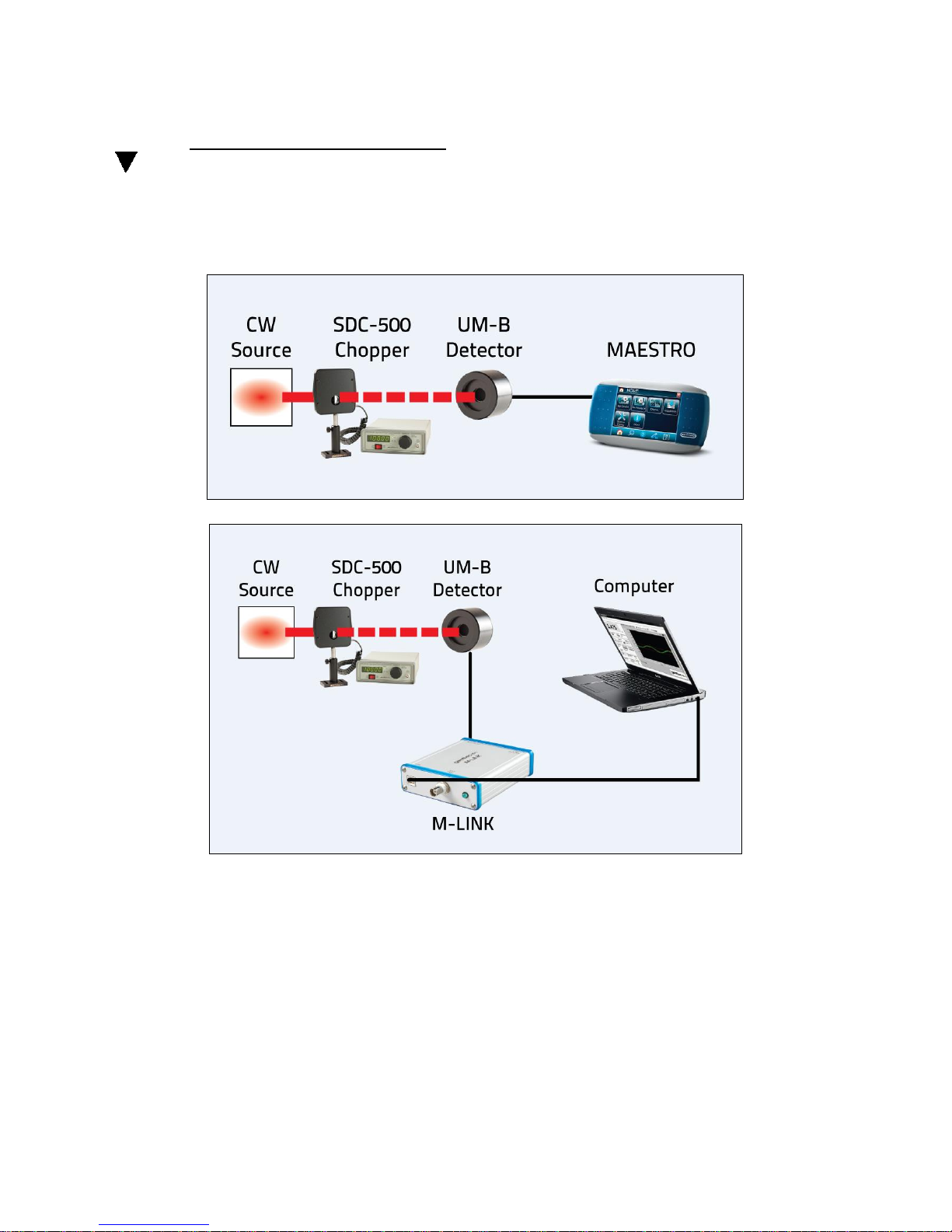
2- Connect the wattmeter to a compatible Gentec-EO laser power monitor (see Fig. 2-1).
(Refer to specifications)
UM-B Series Instruction Manual Gentec Electro-Optics Inc. All rights reserved
Figure 2.1: UM-B with monitor
Page 10

10
4
3
4
Revision 2.1
NOTE: The parameters programmed in the DB-15 “Smart Interface” are for a 1 M load
impedance.
3- Remove the detector's protective cover, when applicable.
4- Put the optical chopper (SDC-500 or equivalent) into the laser beam path and adjust the
frequency at 10Hz (laser beam must be contained within the aperture).
5- Put the wattmeter head into the laser beam path after the chopper (laser beam must be
contained within the aperture).
CAUTION: Be careful not to exceed the maximum levels and densities in: energy, peak
power and average power as stated in the specifications pages.
NOTE: As with all pyroelectric devices, these detectors have some position and beam size
linearity. For the most accurate measurements, the beam should normally be
centered on the sensor surface and the beam diameter should ideally be close to
that of the original calibration conditions, which is 100% encircled power (of a semi-
Gaussian beam stopped at 1/e2) applied to a diameter equal to 80% of the
detector aperture. The use of a divergent lens, a Lambertian diffuser such as opal
glass, or any other method of beam spreading, is recommended for this purpose.
Please take note that all of the laser light must be directed within the detector
aperture and that the transmission loss through the optical component must be
known.
3.2 Working at other wavelengths than 1.064µm
The monitor will automatically configure himself using the data stored in the EEPROM of
the DB-15 “Smart Interface”. This includes the calibration sensitivity and wavelength
corrections for 20 current wavelengths
For more precise measurements with a UM-B Series wattmeter at wavelengths other than
those already corrected by the “Personal wavelength correction
the “Smart Interface”, a correction factor
for the change in sensitivity of the wattmeter caused by the change in absorption of the
optical absorber at different wavelengths. This automatic correction is a linear interpolation
between two measured values of the ‘’Personal wavelength correction’’.
Refer to the spectral curve of the “ Personal Wavelength Correction TM “ certificate supplied with the
wattmeter
Refer to the monitor manuals for instructions.
3
4.
TM
is automatically set in the monitor to compensate
’’ 3 data programmed into
UM-B Series Instruction Manual Gentec Electro-Optics Inc. All rights reserved
Page 11
3.3 When using an oscilloscope:
11
Revision 2.1
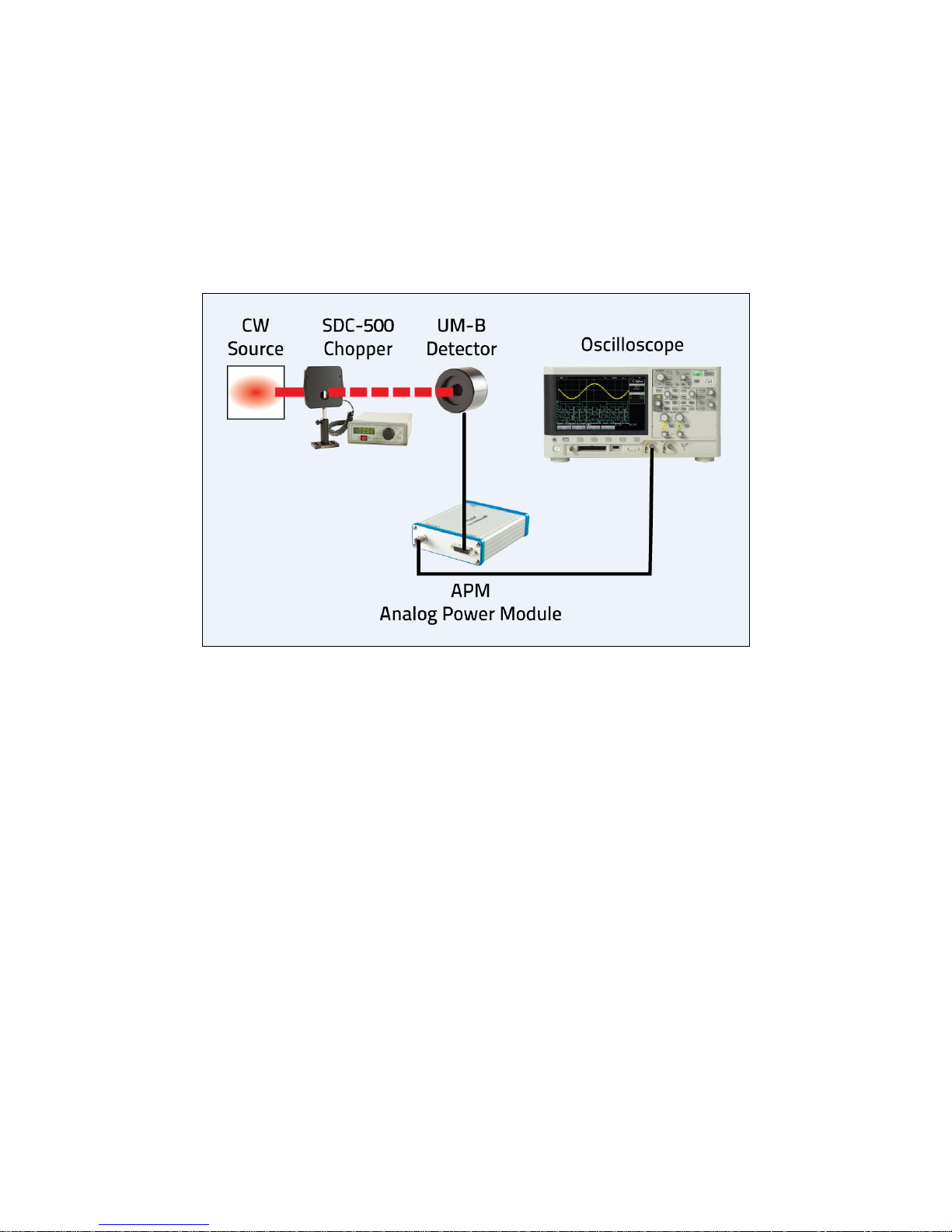
Figure 2.3: UM-B with oscilloscope
3.3.1 General Instructions
1- Install the wattmeter on its optical stand
2- Connect the wattmeter to the APM and switch it on. (Battery or power supply needed)
3- Connect the APM to the oscilloscope.
NOTE: The required load impedance is 1 M and ≤ 30 pF.
4- Put the optical chopper (SDC-500 or equivalent) into the laser beam path and adjust the
frequency at 10Hz (laser beam must be contained within the aperture).
5- Put the wattmeter head into the laser beam path after the chopper (laser beam must be
contained within the aperture).
CAUTION: Be careful not to exceed the maximum levels and densities in: energy, peak
power and average power as stated in the specifications pages.
NOTE: As with all pyroelectric devices, these detectors have some position and beam size
sensitivity. For the most accurate measurements, the beam should normally be
centered on the sensor surface and the beam diameter should ideally be close to
that of the original calibration conditions, which is 100% encircled power (of a semi-
UM-B Series Instruction Manual Gentec Electro-Optics Inc. All rights reserved
Page 12

Revision 2.1
Gaussian beam stopped at 1/e2) applied to a diameter equal to 80% of the
detector aperture. The use of a divergent lens, a Lambertian diffuser such as opal
glass, or any other method of beam spreading, is recommended for this purpose.
Please take note that all of the laser light must be directed within the detector
aperture and that the transmission loss through the optical component must be
known.
6- Adjust the oscilloscope so it triggers on the wattmeter pulse or on the chopper sync. signal.
7- Measure the baseline to peak voltage generated by the wattmeter.
8- Determine the wattmeter Volt/watt sensitivity from the detector identification label or calibration
certificate. Choose the value stated for the wavelength being used.
9- Calculate the optical energy using the following equation:
Power = (V
Ex:
- Detector calibration sensitivity (100 Volts / watt)
Energy = 1 Volt / 100 V/W = 10 mW
NOTE: Exclude any DC offset from the pulse peak value measurement.
- V
peak-Voffset
peak-Voffset
) / Calibration sensitivity
= 1 volt
12
UM-B Series Instruction Manual Gentec Electro-Optics Inc. All rights reserved
Page 13

Revision 2.1
μm064.1@1A
A
K
1
A
μm064.1@A
1
A
μm064.1@A
μm064.1@1A
A
%94
%92
3.3.2 Working at other wavelengths than 1.064µm
For measurements with a UM-B Series wattmeter at wavelengths other than 1.064µm, a
correction factor must be set to compensate for the change in sensitivity of the wattmeter
caused by the change in absorption of the optical absorber at different wavelengths.
To correct for the change in absorption refer to the spectral curve of the “ Personal
Wavelength Correction TM “ certificate supplied for the wattmeter and calculate K by taking
the percentage difference between the absorption @1.064µm and that at the desired
wavelength.
13
Power = (V
Here
A sample calculation follows:
= Absorption of the UM-B
peak-Voffset
= Absorption of the UM-B
) / Calibration sensitivity / K
@ the desired wavelength.
@ 1.064µm
= 92 %.
= 94 %
Ex:
K =
K =
- (V
x 100 = 0.9787 x 100 = 97.87 %
peak-Voffset
x 100
) = 1 volt
- Detector calibration sensitivity @1.064µm (100 Volts / Watt)
Power = 1 Volt / 100 V/W / 97.87% = 10.218 mW
UM-B Series Instruction Manual Gentec Electro-Optics Inc. All rights reserved
Page 14

14
5
Revision 2.1
4 DAMAGE TO THE OPTICAL ABSORBER MATERIALS
At any time, the beam’s incident area should not be less than 10% of the detector’s aperture.
Please check with Gentec-EO to make measurements with such small beams.
Damage is usually caused by exceeding the manufacturer is specified maximum tolerances:
- Average Power Density
- Peak Power Density
- Single Pulse Energy Density
Refer to the UM-B Series wattmeter specifications pages. Damage can also be caused when using
a detector with a contaminated absorber or attenuator surface.
The damage thresholds specified in the specifications section refer to a visible alteration of the
absorber surface. In practice, a slight alteration will not affect the wattmeters response. Consider
the wattmeter to be damaged and/or out of calibration when large-scale damage is evident or you
can see the metal electrode beneath the coating5.
In the case of a TEMoo (Gaussian) beam, the maximum peak power and energy density can be
calculated using the following equation:
Density (power or energy) 2Io
W
Where Io is the total beam power or energy
W is the beam radius at 1/e
NOTE: The beam waist for a TEMoo beam is the radius of a circle centered on the beam axis and
containing 86 % of the beam energy. Ref.: SIEGMAN, A.E., An Introduction to Lasers
and Masers, p. 313 (Mcgraw-Hill Series in the Fundamentals of Electronic Science).
Example of energy density;
Io = 1 joule (total energy)
W = 1 cm
Energy density = 2 x 1 joule = 0.64 joule/cm2
x (1 cm)2
Example of power density calculation;
Io = 1 MegaWatt (total power)
W = 1 cm
Power density = 2 x 1 MegaWatt = 0.64 MW/cm2
Contact Gentec-EO for evaluation, repair, recalibration, or replacement (refer to the WARRANTY
instructions).
2
and = 3.1416
2
UM-B Series Instruction Manual Gentec Electro-Optics Inc. All rights reserved
Page 15

x (1 cm) 2
15
Revision 2.1
UM-B Series Instruction Manual Gentec Electro-Optics Inc. All rights reserved
Page 16

Revision 2.1
OPTIONAL ACCESSORIES
4.1 Other Accessories:
Contact Gentec-EO for a complete list of accessories, their specifications and features.
Partial list:
- APM (for connecting UM-B Series to an oscilloscope).
- MAESTRO monitor
- Carrying case
16
UM-B Series Instruction Manual Gentec Electro-Optics Inc. All rights reserved
Page 17

Revision 2.1
5 APPENDIX A
5.1 Recycling and separation procedure for WEEE directive 2002/96/EC.
This section is used by the recycling center when the detector reaches its end of life. Breaking
the calibration seal or opening the detector will void the detector warranty.
The complete detector contains
1 Detector with wires or DB-15.
1 CD (instruction manual, software and drivers)
1 calibration certificate
1 Personal Wavelength Correction
5.2 Separation:
Paper: certificates
Wires: Cable Detector.
Printed circuit board: inside the Detector and DB-15, no need to separate (less than 10 cm2).
Aluminum: Detector casing.
17
UM-B Series Instruction Manual Gentec Electro-Optics Inc. All rights reserved
Page 18

Revision 2.1
Standard
Description
Performance
Criteria
CISPR 11 :2009
+A1 2010
Industrial, scientific and medical equipment –
Radio- frequency disturbance characteristics –
Limits and methods of measurement
Class A
EN 61000-4-2:2009
Electromagnetic compatibility (EMC) – Part 4-2:
Testing and measurement techniques- Electrostatic
Class B
EN 61000-4-3:2006
+A2:2010
Electromagnetic compatibility (EMC) – Part 4-3:
Testing and measurement techniques- Radiated,
Radio Frequency, electromagnetic field immunity
Class A
5.3 DECLARATION OF CONFORMITY
Application of Council Directive(s): 2004/108/EC EMC Directive
Manufacturer’s Name: Gentec Electro Optics, Inc.
Manufacturer’s Address: 445 St-Jean Baptiste, suite
Representative’s Name: Laser Component S.A.S
Representative’s Address: 45 bis Route des Gardes
Type of Equipment: Laser Power/Energy Meter
Model No.: UM
Year of test & manufacture: 2011
Standard(s) to which Conformity is
declared: EN 61326-1: 2006 Emission
generic standard
18
160 (Québec), Canada G2E
5N7
92190 Meudon (France)
I, the undersigned, hereby declare that the equipment specified
above conforms to the above Directive(s) and
Standard(s)
Place: Québec
(Québec) Date : June 11, 2012
(President)
UM-B Series Instruction Manual Gentec Electro-Optics Inc. All rights reserved
Page 19

19
Revision 2.1
UM-B Series Instruction Manual Gentec Electro-Optics Inc. All rights reserved
Page 20
Revision 2.1
20
UM-B Series Instruction Manual Gentec Electro-Optics Inc. All rights reserved
 Loading...