

Page 1
Page 2

MAESTRO User’s Manual Revision 8.0 1
WARRANTY
The Gentec-EO MAESTRO Single Channel Laser Power, Energy and Power/Energy Meter carries a oneyear warranty (from date of shipment) against material and/or workmanship defects, when used under
normal operating conditions. The warranty does not cover damages related to battery leakage or misuse.
Gentec-EO Inc. will repair or replace, at Gentec-EO Inc.’s option, any MAESTRO that proves to be
defective during the warranty period, except in the case of product misuse.
Any attempt by an unauthorized person to alter or repair the product voids the warranty.
The manufacturer is not liable for consequential damages of any kind.
Customers must fill in and mail the warranty card in order to activate the warranty.
In case of malfunction, contact your local Gentec-EO distributor or nearest Gentec-EO Inc. office to obtain
a return authorization number. The material should be returned to:
Gentec Electro-Optics, Inc.
445, St-Jean-Baptiste, Suite 160
Québec, QC
Canada G2E 5N7
Tel: (418) 651-8003
Fax: (418) 651-1174
e-mail: [email protected]
Website: www.gentec-eo.com
CLAIMS
To obtain warranty service, contact your nearest Gentec-EO agent or send the product, with a description
of the problem, and prepaid transportation and insurance, to the nearest Gentec-EO agent. Gentec-EO
Inc. assumes no risk for damage during transit. Gentec-EO Inc. will, at its option, repair or replace the
defective product free of charge or refund your purchase price. However, if Gentec-EO Inc. determines
that the failure is caused by misuse, alterations, accident or abnormal conditions of operation or handling,
you will be billed for the repair and the repaired product will be returned to you, transportation prepaid.
Page 3

MAESTRO User’s Manual Revision 8.0 2
Refer to the manual for specific Warning or Caution information to avoid any
damage to the product.
DC, Direct Current
SAFETY INFORMATION
Do not use the MAESTRO if the device or the detector looks damaged, or if you suspect that the
MAESTRO is not operating properly.
Appropriate installation must be done for water-cooled and fan-cooled detectors. Refer to the specific
instructions for more information. Wait a few minutes before handling the detectors after power is
applied. Surfaces of the detectors get very hot and there is a risk of injury if they are not allowed to cool
down.
Note: This equipment has been tested and found to comply with the limits for a Class B digital
device, pursuant to part 15 of the FCC Rules. These limits are designed to provide
reasonable protection against harmful interference in a residential installation. This
equipment generates, uses, and can radiate radio frequency energy. If not installed
and used in accordance with the instructions, it may cause harmful interference to radio
communications. However, there is no guarantee that interference will not occur in a
particular installation. If this equipment does cause harmful interference to radio or
television reception, which can be determined by turning the equipment off and on, try
to correct the interference by taking one or more of the following steps:
• Reorient or relocate the receiving antenna.
• Increase the distance between the equipment and receiver.
• Connect the equipment to an outlet that is on a different circuit than the receiver.
• Consult the dealer or an experienced radio/TV technician for help.
Caution: Changes or modifications not expressly approved in writing by Gentec-EO Inc. may
void the user’s authority to operate this equipment.
SYMBOLS
The following international symbols are used in this manual:
Page 4

MAESTRO User’s Manual Revision 8.0 3
TABLE OF CONTENTS
1 THE MAESTRO SINGLE CHANNEL LASER POWER/ENERGY METER ........................................... 6
1.1 INTRODUCTION.................................................................................................................................. 6
1.2 SPECIFICATIONS ............................................................................................................................... 7
1.3 FRONT PANEL DESCRIPTION .............................................................................................................. 9
1.4 TOP PANEL DESCRIPTION ................................................................................................................ 10
2 GETTING STARTED ........................................................................................................................... 13
2.1 HOW TO ACCESS THE DIFFERENT MENUS OF THE MAESTRO’S USER INTERFACE ............................... 14
2.2 QUICK POWER AND ENERGY MEASUREMENT PROCEDURE .................................................................. 16
2.3 DESCRIPTION OF THE MAESTRO NAVIGATION MENU ....................................................................... 19
2.4 HOME ............................................................................................................................................. 20
2.4.1 Set Device ............................................................................................................................. 20
2.4.1.1 Date & Time (Not available on this version, check our web site for new versions) ........................... 21
2.4.1.2 Number of Digits ............................................................................................................................... 21
2.4.1.3 Serial Commands ............................................................................................................................. 22
2.4.1.4 Ethernet ............................................................................................................................................ 23
2.4.1.5 Languages........................................................................................................................................ 24
2.4.2 Set Measure .......................................................................................................................... 25
2.4.2.1 Wavelength ...................................................................................................................................... 26
2.4.2.2 Range ............................................................................................................................................... 28
2.4.2.3 Measure Mode ................................................................................................................................. 29
2.4.2.4 Corrections ....................................................................................................................................... 32
2.4.2.5 Trigger Level .................................................................................................................................... 33
2.4.3 Display ................................................................................................................................... 34
2.4.3.1 Display Parameters menu bar ................................ .......................................................................... 35
2.4.3.2 Real time display .............................................................................................................................. 38
2.4.3.3 Scope display ................................................................................................................................... 38
2.4.3.4 Needle display .................................................................................................................................. 40
2.4.3.5 Averaging display ............................................................................................................................. 40
2.4.3.6 Statistics display ............................................................................................................................... 42
2.4.4 Acquisition ............................................................................................................................. 45
2.4.5 Startup Config........................................................................................................................ 48
2.4.6 About ..................................................................................................................................... 49
2.5 SEARCH ....................................................................................................................................... 50
2.6 INFO ............................................................................................................................................. 51
2.7 MANAGE USB .............................................................................................................................. 52
2.8 BACK TO MEASURE BUTTON .................................................................................................... 52
3 SERIAL COMMUNICATION INTERFACE .......................................................................................... 53
3.1 USB SERIAL COMMUNICATION ........................................................................................................ 53
3.1.1 Installation ............................................................................................................................. 53
3.1.1.1 Installation for Windows™: ............................................................................................................... 53
3.1.2 Setting up Communication to the MAESTRO ....................................................................... 53
3.1.2.1 Verify COM Port ............................................................................................................................... 53
3.1.2.2 Connect to the MAESTRO ............................................................................................................... 53
3.1.2.3 To echo commands .......................................................................................................................... 54
3.1.2.4 Test the connection .......................................................................................................................... 54
3.1.2.5 HyperTerminal settings shortcut ....................................................................................................... 54
3.2 ETHERNET COMMUNICATION ........................................................................................................... 55
3.3 PC-MAESTRO USER-FRIENDLY SERIAL DATA ACQUISITION SOFTWARE ............................................. 56
3.4 TRADITIONAL COMMUNICATION SETTINGS ........................................................................................ 57
3.4.1 Serial Command format ........................................................................................................ 57
3.4.1.1 Serial Protocol Rules: ....................................................................................................................... 57
3.4.1.2 Text mode rules: ............................................................................................................................... 57
3.4.2 MAESTRO Binary Mode Description .................................................................................... 58
3.4.2.1 Description ....................................................................................................................................... 58
Page 5

MAESTRO User’s Manual Revision 8.0 4
3.4.2.2 Codification....................................................................................................................................... 58
3.4.3 Serial Command Directory .................................................................................................... 59
3.4.3.1 Serial commands ................................................................ .............................................................. 61
3.4.3.2 Error Messages ................................................................................................................................ 76
3.4.4 Legacy monitor serial commands.......................................................................................... 77
3.4.4.1 Emulated SOLO2 Serial commands ................................................................................................. 77
3.4.4.2 Error Messages for SOLO2 Serial mode .......................................................................................... 88
4 MAINTENANCE ................................................................................................................................... 89
4.1 USB INSTALLATION FOR THE MAESTRO ......................................................................................... 89
4.2 FREE SOFTWARE UPGRADE ............................................................................................................ 89
4.3 BATTERY CHARGING ....................................................................................................................... 89
4.4 TROUBLESHOOTING ........................................................................................................................ 89
5 DECLARATION OF CONFORMITY .................................................................................................... 90
6 APPENDIX A ....................................................................................................................................... 91
6.1 QED/12/25/50/65/95 ..................................................................................................................... 91
7 APPENDIX B ....................................................................................................................................... 93
7.1 RECYCLING AND SEPARATION PROCEDURE. ...................................................................................... 93
7.2 SEPARATION: .................................................................................................................................. 93
7.3 DISMANTLING PROCEDURE: ............................................................................................................. 93
Page 6

MAESTRO User’s Manual Revision 8.0 5
LIST OF ILLUSTRATIONS
FIG. 1-1 MAESTRO FRONT PANEL ................................................................................................................. 9
FIG. 1-2 MAESTRO TOP PANEL ................................................................................................................... 10
FIG. 1-3 TYPICAL PULSE SHAPE OF A PYROELECTRIC DETECTOR ...................................................................... 12
FIG. 2-1 MAESTRO START UP WINDOW ........................................................................................................ 13
FIG. 2-2 HIERARCHY OF THE MAESTRO’S USER INTERFACE STRUCTURE ........................................................ 14
FIG. 2-3 PARAMETERS MENU TO SET THE DETECTOR’S ZERO LEVEL ................................................................. 17
FIG. 2-4 THE NAVIGATION MENU BAR .............................................................................................................. 19
FIG. 2-5 THE HOME MENU WINDOW............................................................................................................... 20
FIG. 2-6 THE SET DEVICE MENU WINDOW ....................................................................................................... 21
FIG. 2-7 THE NUMBER OF DIGITS MENU WINDOW ............................................................................................. 22
FIG. 2-8 SERIAL COMMANDS MENU WINDOW ................................................................................................... 23
FIG. 2-9 ETHERNET CONFIGURATION MENU WINDOW ....................................................................................... 24
FIG. 2-10 LANGUAGE CONFIGURATION MENU WINDOW .................................................................................... 25
FIG. 2-11 THE SET MEASURE MENU WINDOW.................................................................................................. 26
FIG. 2-12 THE WAVELENGTH MENU WINDOWS ................................................................................................ 27
FIG. 2-13 POPUP WINDOW TO ENTER A USER DEFINED WAVELENGTH ............................................................... 28
FIG. 2-14 THE RANGE SELECTION MENU WINDOW ........................................................................................... 29
FIG. 2-15 THE MEASURE MODE SELECTION MENU WINDOW FOR A THERMOPILE DETECTOR HEAD ....................... 30
FIG. 2-16 SETTING CORRECTION MENU .......................................................................................................... 32
FIG. 2-17 TRIGGER LEVEL WINDOW ................................................................................................................ 33
FIG. 2-18 DISPLAY MENU WINDOW .................................................................................................................. 35
FIG. 2-19 THE DISPLAY PARAMETERS MENU BAR ............................................................................................ 35
FIG. 2-20 REAL TIME DISPLAY ........................................................................................................................ 38
FIG. 2-21 SCOPE TIME DISPLAY ...................................................................................................................... 39
FIG. 2-22 DIGITAL NEEDLE DISPLAY ................................................................................................................ 40
FIG. 2-23 AVERAGING DISPLAY....................................................................................................................... 41
FIG. 2-24 STATISTICS DISPLAY ....................................................................................................................... 42
FIG. 2-25 STATISTICS SETTINGS POPUP WINDOW ............................................................................................ 43
FIG. 2-26 STATISTICS DURATION SETTINGS POPUP WINDOW ............................................................................ 44
FIG. 2-27 DATA SAMPLING PARAMETERS WINDOW MENU. ................................................................................. 46
FIG. 2-28 STARTUP CONFIG MENU WINDOW .................................................................................................... 48
FIG. 2-29 ABOUT WINDOW. ............................................................................................................................ 49
FIG. 2-30 SEARCH WINDOW. .......................................................................................................................... 50
FIG. 2-31 INFORMATION MENU WINDOW .......................................................................................................... 51
FIG. 2-32 MANAGE USB MENU WINDOW ......................................................................................................... 52
FIG. 3-1 MAESTRO ETHERNET COMMUNICATION EXAMPLE APPLICATION ....................................................... 56
Page 7

MAESTRO User’s Manual Revision 8.0 6
1 THE MAESTRO SINGLE CHANNEL LASER POWER/ENERGY METER
1.1 Introduction
To obtain the full performance from the MAESTRO, we recommend that you read this manual carefully.
The MAESTRO is a microprocessor-based power and energy meter that uses the latest technology to
provide a multitude of options in a user-friendly environment. It is intuitively accessible using a touch
screen. It is a complete power and energy meter. The MAESTRO provides a statistical analysis of your
measurements. It allows you to store data on an external USB key. Moreover, the MAESTRO can be
updated by connecting a USB key with the new file available on our web site in the download section.
The MAESTRO has enhanced network capabilities that take further advantage of the USB port for data
acquisition and remote control. In addition to the external USB key, it can also transfer data files to a PC
for more sophisticated data analysis. Furthermore, the MAESTRO responds to commands through the
PC interface using the USB port. To transform your PC screen into a virtual MAESTRO, look for the
easy-to-use communications software on our website.
There is no need to enter the head specifications when connecting the new Gentec-EO power or energy
detector heads, for heads version 5 and above. The MAESTRO is already internally set to accept the
latest Gentec-EO wattmeter and joulemeter heads with a DB-15 connector. The MAESTRO supports
both fast and slow heads with a rise time from 5 s to 10 s.
The MAESTRO can reread heads in hot plug situation. Before inserting a new head, wait for the
MAESTRO to stop displaying numbers. Once the head has been detected, the monitor will wait 2
seconds to ensure that the head is properly inserted. If you do not respect these conditions and the head
is not read correctly, reboot the MAESTRO.
Unpacking
Each Gentec-EO MAESTRO is thoroughly tested and calibrated prior to shipment.
Visually inspect every MAESTRO unit after removing it from the shipping containers. If you see any
damage, retain all packaging materials and shipping receipts. Any damage claim should be made
promptly to the transportation company. Notify the nearest Gentec-EO representative concerning the
claim, so that any repair or replacement can be arranged as soon as possible.
Easy software upgrade
Keep in touch with the latest improvements to our user-friendly software by going to our website at
www.gentec-eo.com. Download the latest software version anytime and install it on the MAESTRO with
the USB key. You will find all the necessary information on downloading and upgrading in section 4.2.
Page 8

MAESTRO User’s Manual Revision 8.0 7
Power meter specifications
Power Range
4 pW to 30 kW
Power Scales
(photo diode head)
300pW, 1nW, 3nW, 10nW, 30nW, 100nW, 300nW, 1µW, 3µW, 10µW,
30µW, 100µW, 300µW, 1mW, 3mW, 10mW, 30mW, 100mW, 300mW,
1W, 3W
Power Scales
(thermal head)
16 scales: 300uW, 1mW, 3mW, 10mW, 30mW, 100mW, 300mW, 1W,
3W, 10W, 30W, 100W, 300W, 1kW, 3kW, 10kW, 30kW
Pyroelectric in power
mode range (UM-B)
100µW, 300µW, 1mW, 3mW, 10mW, 30mW, 100mW, 300mW
Resolution (digital)
Current scale/8192
Monitor Accuracy
±0.25 % 5 µV best scale1
Response Time
(accelerated)2
Head dependant (~1 sec)
Statistics
Current value, Max, Min, Average, Std Dev., RMS stability, PTP stability,
Time
Data Storage
Continuous on USB stick
Energy meter specifications
Energy Range
2fJ to 30kJ
Energy Scales
[2]
(photo diode head)
300fJ, 1 pJ, 3 pJ, 10 pJ, 30 pJ, 300pJ, 1 nJ, 3 nJ, 10 nJ, 30 nJ, 100nJ,
300nJ, 1 uJ, 3 uJ,10uJ, 30uJ, 100µJ, 300µJ, 1mJ, 3mJ, 10mJ, 30mJ
Energy Scales
[2]
(thermal head)
3mJ, 10mJ, 30mJ, 100mJ, 300mJ, 1J, 3J, 10J, 30J, 100J, 300J, 1kJ, 3kJ,
10kJ, 30kJ
Resolution (digital)
Current scale/8192
1
2
1.2 Specifications
The following specifications are based on a one-year calibration cycle, an operating temperature of 18 to
28ºC (64 to 82ºF) and a relative humidity not exceeding 80%.
Table 1-1 List of Specifications
The 5µV offset can introduce an error into low power measurements with low sensitivity detectors. It is
essential to use the Zero Offset to rezero the Maestro before making a measurement in these conditions.
It is always good practice to use the Zero Offset. See section 2.2.
Varies with detector head.
Page 9

MAESTRO User’s Manual Revision 8.0 8
Accuracy3
1.0 %50 µV < 6 kHz
2%50 µV 6kHz to 10 kHz
Default Trigger Level
2 %
SOFTWARE
TRIGGER LEVEL
0.1% to 99.9%, 0.1% resolution
Repetition
Frequency4
2 kHz for data acquisition in the real time full screen display, no missing
point
1.3 kHz for data acquisition in real time with time stamp, no missing point
2 kHz in statistics mode, no missing point
From 2 kHz to 10kHz the MAESTRO will send the latest energy pulse
every 500us. (corresponding to a subsampling at 2 kHz).
Frequency
Measurement
Accurate frequency measurement up to 14kHz
0-1000 Hz: 0.1% accuracy
1000-2000 Hz: 0.5%
2000-14000 Hz: 1%
Statistics
Current value, Max, Min, Average, Std Dev., RMS stability, PTP stability,
Time, Pulse #, Repetition Rate, Avg Power.
Data Storage
Continuous on USB stick
General Specifications
Digital Display
112.9 x 84.7mm RGB color LCD with touchscreen, 640 x 480 Pixels
Display Rate
3 Hz numeric display
15 Hz bar graph & needle display
Scope
500 divisions
Data Displays
Real time, Scope, Averaging, Statistics, Digital tuning needle
User input correction
factors
1 multipliers and 1 offsets (7 digits floating point)
Analog Output
0 – 1 volt, full scale, ± .5%
Internet Upgrades
USB STICK
PC Serial Commands
USB & Ethernet5
& RS-232
No missing point
throughput serial
300 Hz
3
4
5
Including linearity, detector dependant.
In a full size statistic’s windows, no scope display and no serial communication.
USB cable included. RS-232 cable must be purchased separately.
6
Backlight at 50% in real time display. The scope and averaging displays decrease the autonomy by
20%.
Page 10
MAESTRO User’s Manual Revision 8.0 9
frequency
Dimensions (without
stand)
216 mm(W) x 122 mm (H) x 45.7 mm (D)
Weight (with stand)
0.670 kg
Battery Pack
4 rechargeable 1.2 V Ni-MH AA
Battery life
6.5 hours6
Battery charge time
4 hours
Universal External
Power Supply
Input: 100/240 VAC 50-60 Hz, Output 9 VDC 1.66 A.
2
1
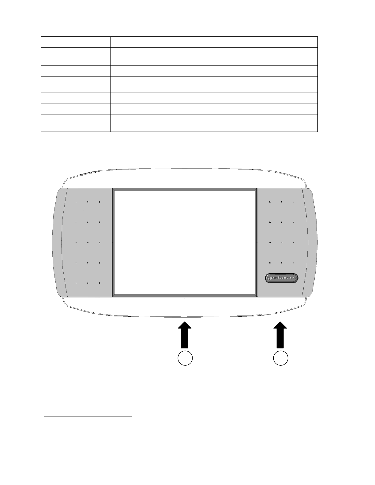
1.3 Front Panel Description
1- I/O control key.
Fig. 1-1 MAESTRO Front Panel
Page 11
MAESTRO User’s Manual Revision 8.0 10
CAUTION
Permanent damage may occur to the optical meter if an external
power supply other than the Gentec-EO P/N 200960A is used.
Please call Gentec-EO or your local distributor if extra power
supplies are needed.
6 5 4 3 2
1
Pressing the I/O key quickly when the MAESTRO is OFF turns the MAESTRO ON (do
not hold the I/O key). To turn the MAESTRO off, press the I/O key. To prevent battery
leakage and to increase battery life, we recommend switching the MAESTRO off when
not in use.
2- LCD SCREEN
Dimensions: 112.9 x 84.7mm RGB color Touchscreen LCD, 640 x 480 Pixels.
To access any of the options or menus, simply touch the appropriate icon or button on the
screen.
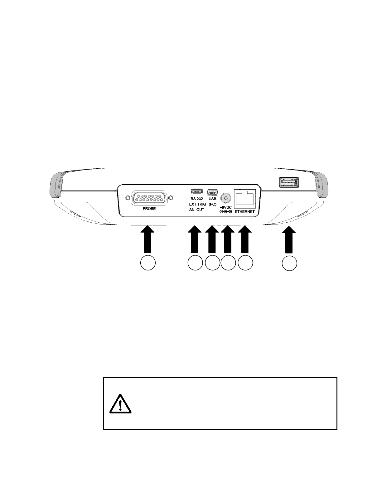
1.4 Top Panel Description
Fig. 1-2 MAESTRO Top Panel
1- USB PORT FOR USB KEY
This interface allows the user to insert a USB key for an easy and quick data transfer
without having to connect the monitor to a PC. If your key is not recognized, try using a
new one. Old and slow USB keys are not supported.
2- ETHERNET PORT
This interface allows remote control and data transfers between the MAESTRO and a
computer that has an ETHERNET communication port.
3- EXTERNAL POWER SUPPLY INPUT JACK:
Input voltage required: 9 VDC/1.66A. If input voltage is between 15 and 25 volts, the
monitor will switch to USB power or battery power. If the input power is above 26 volts,
Page 12

MAESTRO User’s Manual Revision 8.0 11
selected Range ofMax outputVPower
selected Range ofMax outputVEnergy
either the internal fuse will blow or the monitor may be damaged, depending on the
voltage level and the waveform.
4- USB INTERFACE CONNECTOR:
This interface allows remote control and data transfers between the MAESTRO and a
computer that has a USB communication port.
5- SERIAL INTERFACE CONNECTOR (RS-232, Analog out, Ext trigger):
RS-232:
The RS-232 interface allows remote control and data transfers between the
MAESTRO and a computer, a terminal, or any device that has a serial
communication port. To use the RS-232 port, you must have a special cable
(part number 201860).
Analog out:
It allows monitoring the laser average power or energy by using external
equipment such as a chart recorder, a computer with an analog interface, a
voltmeter, etc. To use the analog output port, you must have a special cable
(part number 201958).
For power measurements: the output signal represents the amplified and
anticipated power detector response.
For energy measurements: the output signal is a DC voltage representing the
pulse energy value.
The 1 V value corresponds to the full scale reading of the selected range. It
provides the best signal-to-noise ratio. The measured power or energy is then
related to the output voltage and to the selected range according to the following
equations:
For example:
1.00 V corresponds to 10 Watt on the 10 W range
0.25 V corresponds to 2.5 Watt on the 10 W range
0.10 V corresponds to 30 mW on the 300 mW range
Specifications:
Maximum output voltage: 1 V
Output impedance: 2 k
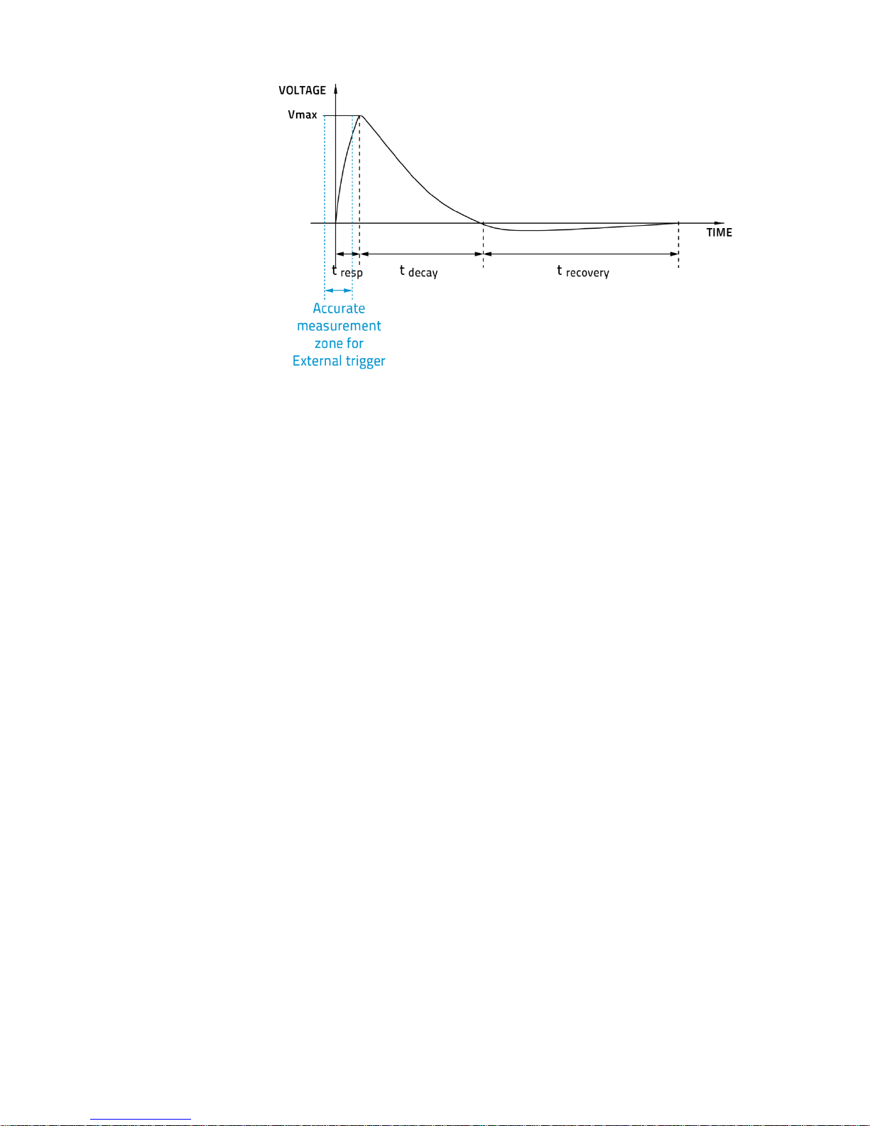
External trigger:
To use the external trigger, you must use a special cable (part number 201956).
The External trigger is TTL compatible. The maximum voltage is 25 volts, the
trigger needs a positive voltage, the minimum width is 1 s. The monitor detects
the trigger on the rising side of the external trigger signal. To measure accurately,
the trigger must be just before the laser pulse, or just after. For example:
A QE12SP-S-MT has a 20 s rise time
The External trigger must be 4 s before or 19 s after the laser pulse.
Page 13
MAESTRO User’s Manual Revision 8.0 12
Fig. 1-3 Typical pulse shape of a pyroelectric detector
Connector type: cable sold separately
6- PROBE INPUT JACK:
The MAESTRO uses a DB-15 female connector to mate with the detector heads (probes).
The MAESTRO works with all the latest Gentec-EO detectors except the specialty high
rep rate detectors. It automatically recognizes every power detector head, which ensures
accurate auto-calibration. More importantly, it can take advantage of our Personal
wavelength correction™. It reads the memory in the Smart Interface connector (version 5
and higher) to provide a wavelength correction that is based on spectral data measured
from that specific detector.
The MAESTRO may not recognize some of the old heads EEPROM versions. An error
message “Detector not supported!” will appear in a popup window. Please contact a
Gentec-EO representative to resolve this issue. If no message is displayed, either the
head is not supported or it is broken.
Energy detector heads prior to version 4 have a BNC connector. The user must use a
universal BNC/DB-15 adaptor to connect an energy detector head to the MAESTRO. This
adaptor is compatible with all the Gentec-EO pyroelectric joulemeters except the EPD.
Power detectors of version V5 and higher and Energy detectors of version V6 and
higher are equipped with an “intelligent” DB-15 male connector that mates directly to the
DB-15 female connector. They do not require an adaptor.
WARNING: This DB-15 connector, though similar to that of the former TPM-310 and TPM-330
monitors, is incompatible with the power detector heads of PS-310 Series Version 1
and PS-330 Series Version 1. These heads used a different technology and do not
have the same pin-out configuration.
Any attempt to modify connectors of the early version heads to mate with the MAESTRO
can result in damage to the monitor.
Page 14
MAESTRO User’s Manual Revision 8.0 13
1 2 3
4
2 GETTING STARTED
This section contains important information concerning the installation and operation of the
MAESTRO.
The MAESTRO is delivered ready to use. Just insert a detector head in the Probe Input Jack (#6 in
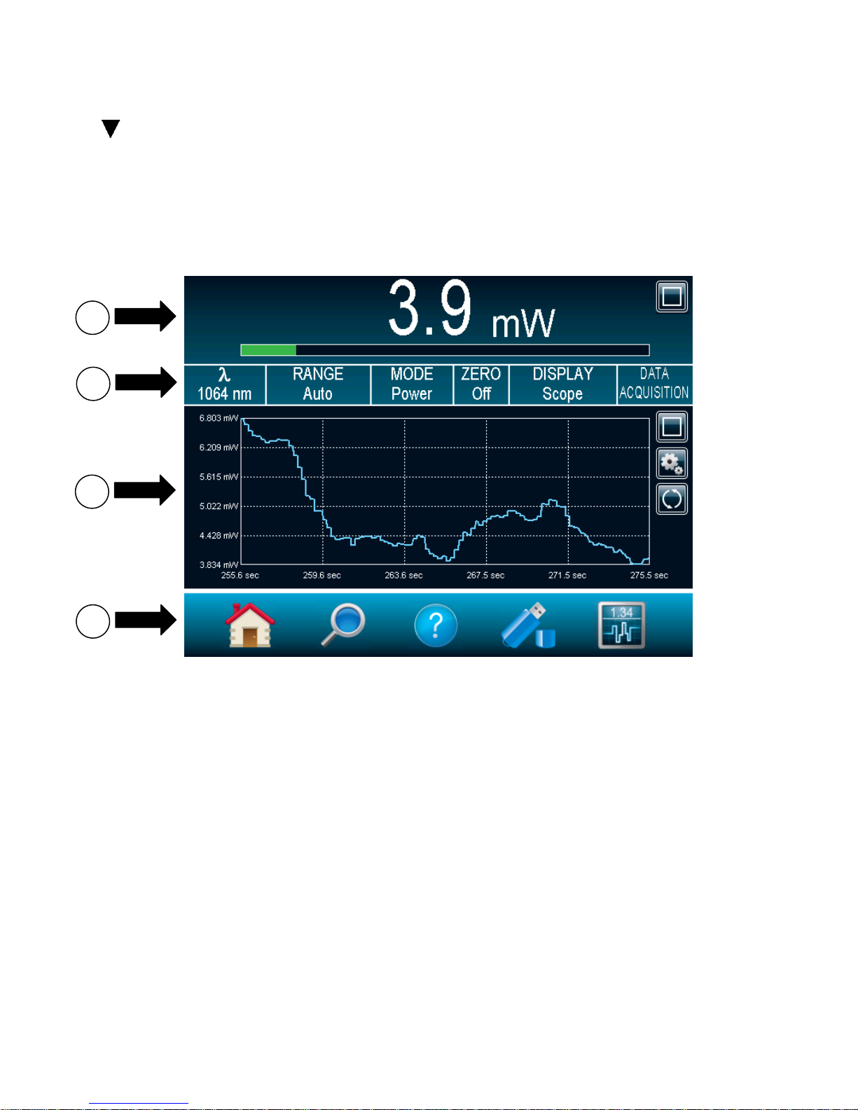
Figure 1-2) and press the I/O key. The following window will appear on the monitor (Figure 2-1). It is
separated into four different areas.
Fig. 2-1 MAESTRO Start up window
1- REAL TIME DISPLAY (in dual mode)
The Real Time display shows the current measured value by the detector head (refer to
section 2.4.3.2).
2- DISPLAY PARAMETERS MENU
The Display Parameters menu gives you quick access to the MAESTRO’s main settings
(refer to section 2.4.3.1).
3- SCOPE DISPLAY (in dual mode)
The Scope display gives a quick look at the laser beam’s long-term stability and trend as
a function of time. This display can be easily changed using the display parameters menu
(refer to section 2.4.3.3).
4- NAVIGATION MENU (main menu)
The Navigation menu allows you to navigate through the different menu windows to set
the MAESTRO’s options to your specific needs (refer to section 2.3).
Page 15
MAESTRO User’s Manual Revision 8.0 14
2.1 How to access the different menus of the MAESTRO’s user interface
The powerful CPU of the MAESTRO, combined with the Windows CE operating system, provides an
easy and intuitive access to all of its functions. The user controls the intuitive interface using the touch
screen. To access any option or functionality, simply touch the appropriate icon or button on the touch
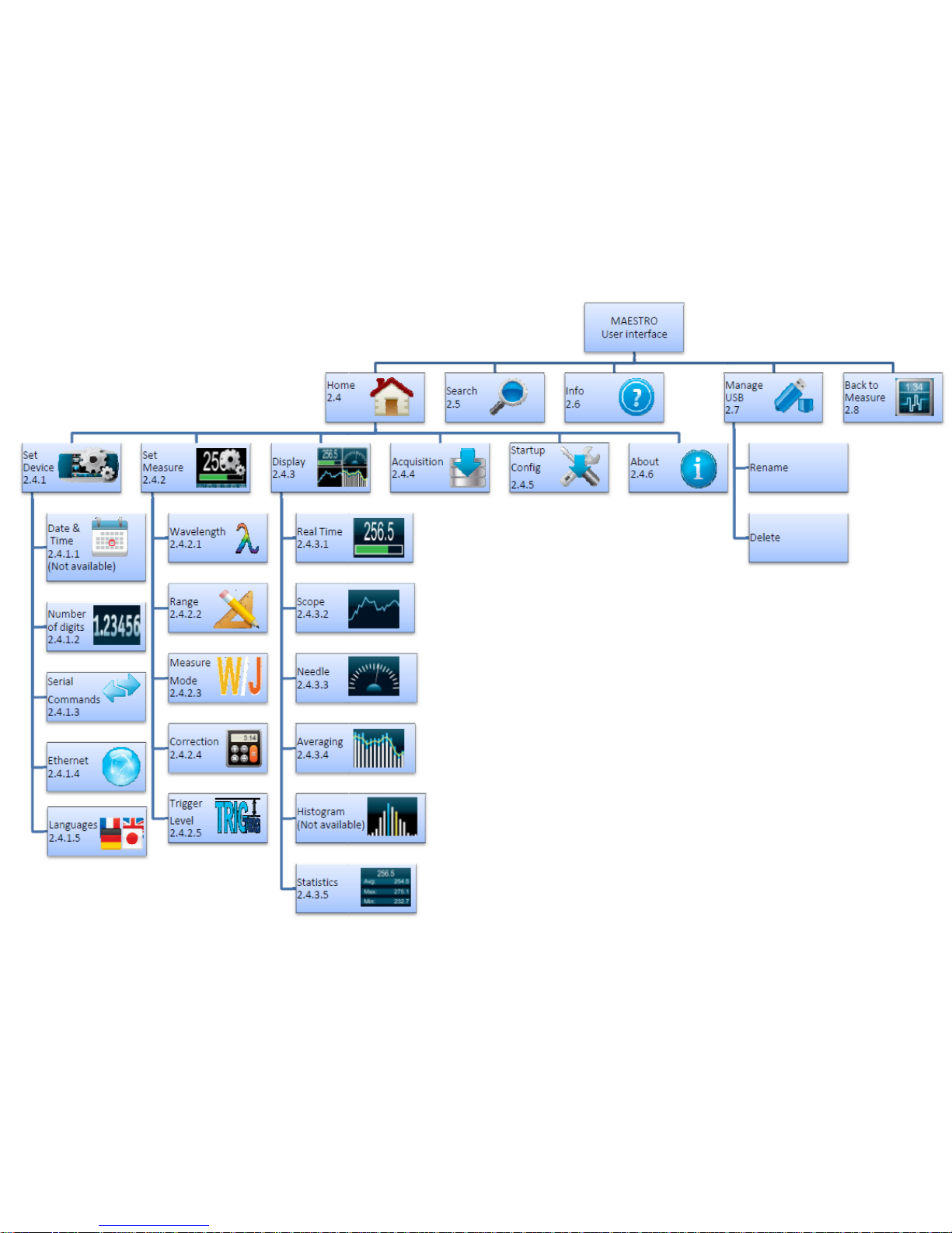
screen. To help you navigate through the different menus, the following figure represents the
MAESTRO’s user interface hierarchy. Each menu and submenu is represented by its icon and
referenced to its corresponding detailed section. (Some functions may not be available in your software
version, check our web site for new release),
Fig. 2-2 Hierarchy of the MAESTRO’s user interface structure
Page 16
MAESTRO User’s Manual Revision 8.0 15
Icon
Name
Type
Description
Cancel
Button
Closes current window without saving
changes.
OK
Button
Saves changes and closes current
window.
Warning
Icon
Identifies a warning window.
Hint
Icon
Identifies a useful hint.
Full Screen
Button
Switches to the single, full screen
display mode.
Minimize
Button
Switches to the dual screen display
mode.
Settings
Button
Allows the user to change the display
settings.
Play
Button
Starts computing the statistics.
Refresh
Button
Refreshes the data in the display
(used for Scope, Averaging and
Histogram).
Stop
Button
Stops computing the statistics.
Check Box (empty)
Check Box
Deactivates the option.
Check Box (full)
Check Box
Activates the option.
Edit
Button
Allows user to edit the field.
Delete
Button
Erases the field.
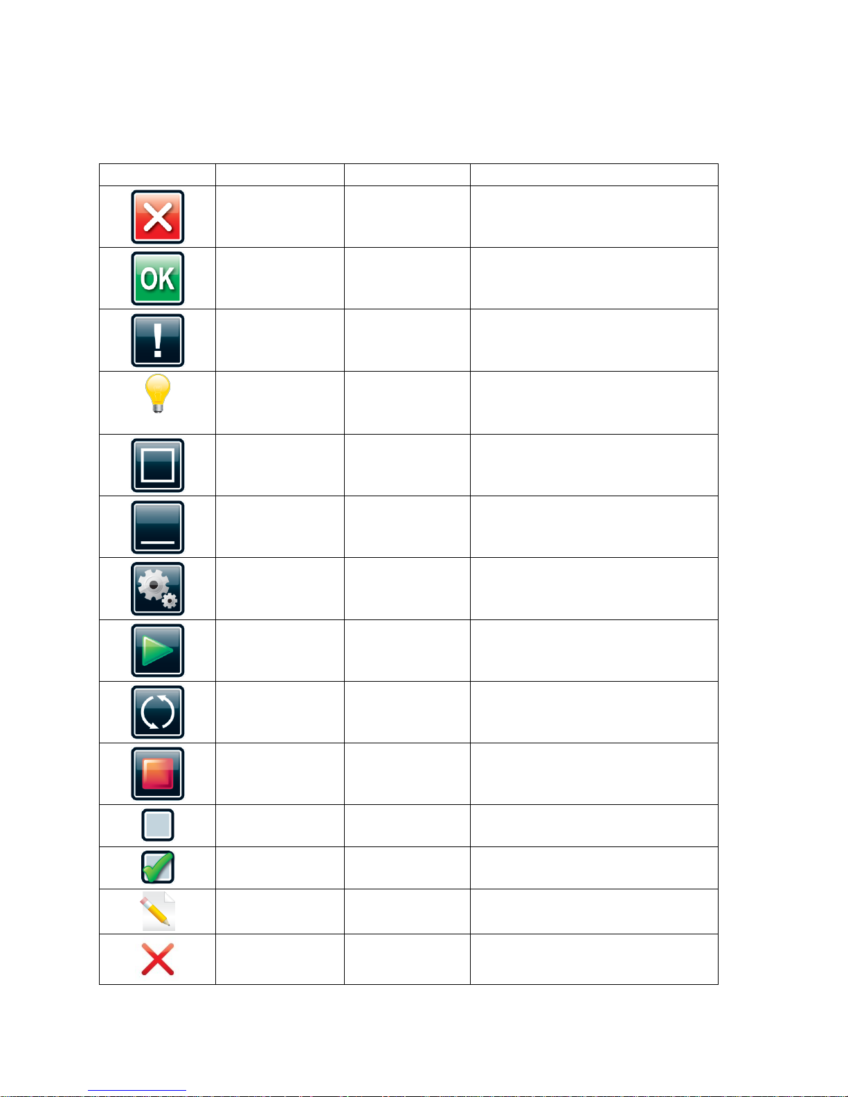
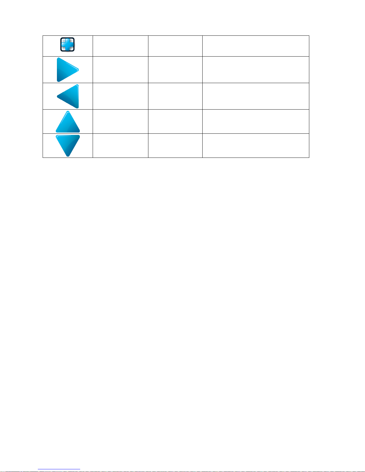
A set of different buttons and icons allows you to interact with the MAESTRO’s user interface. The
following table describes the different buttons and icons present in the MAESTRO.
Table 2-1 List of Specifications
Page 17
MAESTRO User’s Manual Revision 8.0 16
Add
Button
Automatically adds a file name.
Pressing the Add button again
increments the name.
Next Page
Button
Displays the next page in the menu.
Previous Page
Button
Displays the previous page in the
menu.
Scroll up
(Not available)
Button
Displays the upper part of the page.
Scroll down
(Not available)
Button
Displays the lower part of the page.
2.2 Quick power and energy measurement procedure
This section applies to all MAESTRO versions. It will show you the fastest way of making a laser power
and energy measurement with the MAESTRO and a Gentec-EO power or energy detector.
The monitor automatically recognizes all the Gentec-EO power heads and energy heads of version 4 or
higher. All customized technical data required for optimum operation of the detector will be automatically
downloaded from the EEPROM in the DB-15 connector. These data include all the necessary head
parameters such as sensitivity, model, serial number, version, wavelength correction factors, time
response and others. The MAESTRO doesn’t support energy detectors before version 4.
Quick power and energy measurement procedure:
1- Install the power or energy detector head on its optical stand.
2- First, slide the connector latch to the right to unlock the connector.
3- Turn the MAESTRO off and connect a compatible power or energy detector head to the
MAESTRO using the PROBE INPUT JACK (see Fig. 1-2). The Maestro allows hot-swapping
between heads.
4- Slide the latch to the left to lock the connector into place.
5- Switch the MAESTRO ON using the I/O key.
6- Power heads will default the MAESTRO to power measurement; energy heads will default the
MAESTRO to energy measurement. The display will default to a dual display in real time and
scope (Fig 2-1) in auto range mode.
7- Remove the head’s protective cover and start the laser.
Put the detector head into the laser beam path. Leave it there for a few minutes, until the
detector has reached an equilibrium temperature. The entire laser beam must be within the
sensor aperture. Do not exceed maximum specified densities, energies or powers. For the
most accurate measurement, spread the beam across 60% to 80% of the sensor area.
Attention: Power heads can be used with both CW and pulsed lasers.
- Energy heads can only be used with pulsed lasers.
Page 18
MAESTRO User’s Manual Revision 8.0 17
Adjusting the zero (step 8a for power heads and 8b for photodiode heads)
8- The power read by the MAESTRO when no laser beam is incident on the detector may not be
exactly zero. For power measures, this is because the detector is not thermally stabilized OR
there was a heat source in the field of view of the detector when you turned on the MAESTRO.
As for photodiode measures, zeroing will remove the detector’s offset.
a. Block off laser radiation to the detector. To reset the zero, wait until the reading
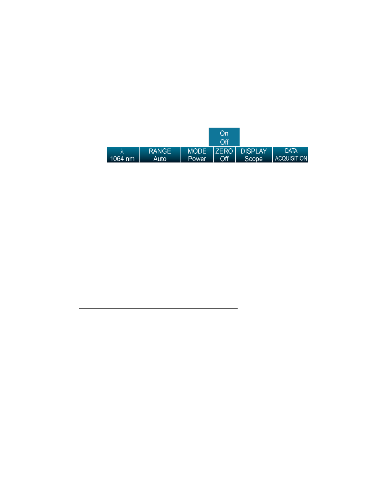
has stabilized and touch Zero in the parameters menu. Two options will appear
(On or Off), select On. You are now ready to take an accurate measurement. To
turn the Zero Offset off, select Off.
Fig. 2-3 Parameters menu to set the detector’s zero level
b. If you have connected a photodiode to the MAESTRO, you must cover the diode
and the zero has to be done for all scales. You will not have to do this manually
for each scale as this is automatically done when you turn “on” the zero. In some
software versions, a message appears requesting you to put the black cover over
your photodiode. Touch the OK button after you have done so. The MAESTRO
passes through all the scales to determine the zero diode for each scale. The
message “Diode Zero Done” appears when the MAESTRO has determined the
zero diode.
Notes:
• Refer to specific power detector documentation for complete installation and operating
instructions.
• Power detectors are thermal sensors and are thus sensitive to temperature variations.
For high-precision measurements, it is recommended to:
• Allow the power detector temperature to stabilize before zeroing the MAESTRO.
• Touch only the stand when handling the power detector. Do not touch the detector head.
• Do not zero adjust the energy detectors, such as the QE series.
Avoid forced airflow or drafts around the detector.
Page 19

MAESTRO User’s Manual Revision 8.0 18
9- Apply the laser beam to the detector head.
10- The laser beam average power or energy can be displayed in four ways for your convenience:
a. Digitally for real time measurements;
b. On a scope graph to evaluate the laser’s variations in time;
c. On a digitally produced analog display using a needle for easy visualization of the
laser beam power variation during laser fine-tuning;
d. Averaged over a certain number of measurements;
e. Complete statistical results over a certain period of time.
Page 20
MAESTRO User’s Manual Revision 8.0 19
Option
Icon
Description
HOME
Allows you to manage the MAESTRO’s and the detector head’s
settings. You will have access to:
Device settings
Measurement settings
Display settings
Acquisition settings
Information about the MAESTRO device
SEARCH
This option allows the user to easily access, in alphabetical order,
some of the available functions on the MAESTRO.
INFO
Displays the MAESTRO’s and the connected detector head’s
information and settings
MANAGE USB
Allows you to manage the USB key. It displays the files currently on
the USB key and lets you rename or delete a file.
BACK TO
MEASURE
Returns to the measurement window.
2.3 Description of the MAESTRO navigation menu
This section describes the first group of menus essential to the MAESTRO’s operation. Refer to Figure
2-2 for a schematic view of the menu structure.
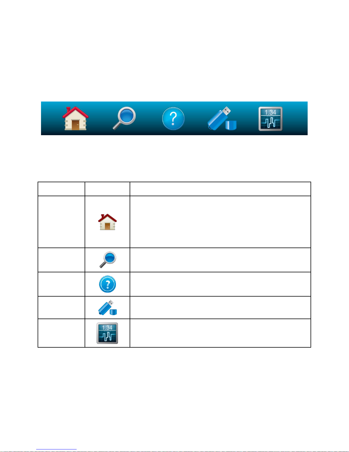
The navigation menu bar provides access, at any time, to the five main options by touching the
appropriate icon.
Fig. 2-4 The navigation menu bar
Table 2-2 List of Navigation menu bar options
By touching an icon in the navigation menu, the MAESTRO will display the appropriate menu window,
allowing you to set or select the desired settings or options.
Page 21
MAESTRO User’s Manual Revision 8.0 20
2.4 Home
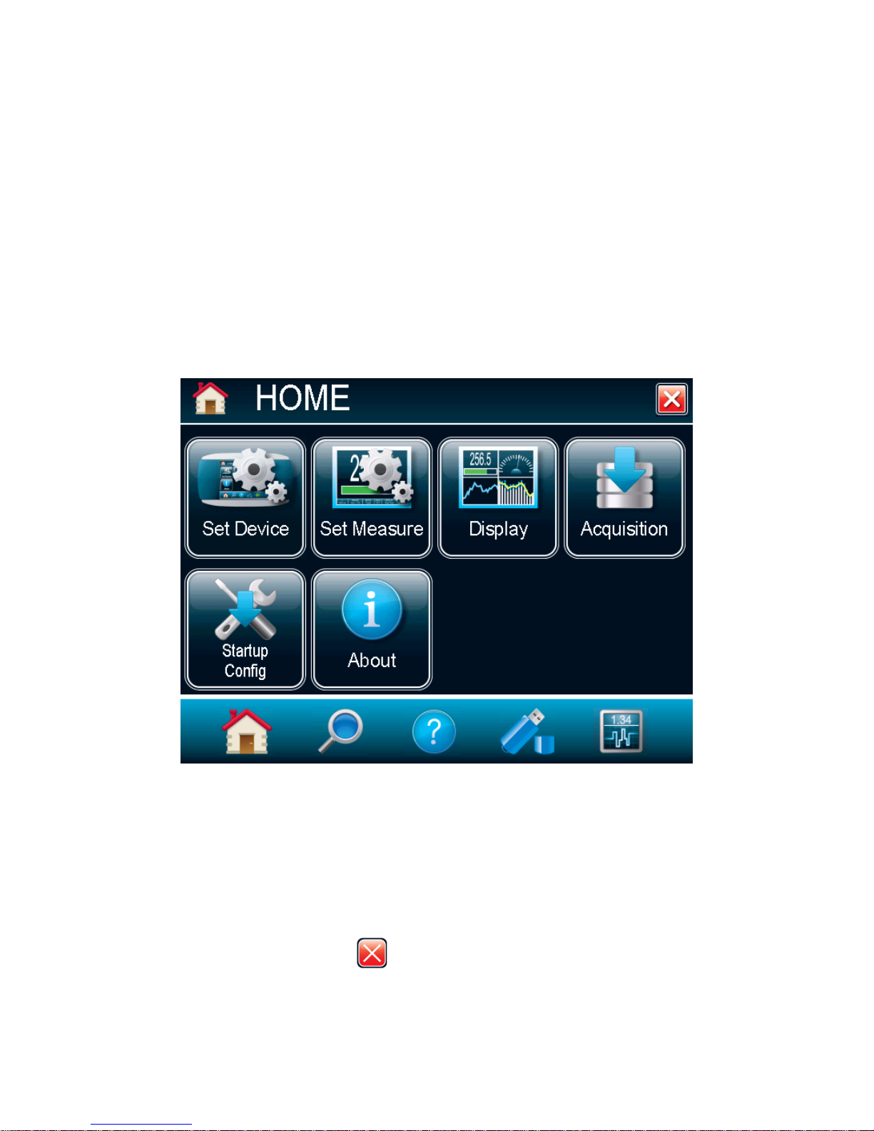
The Home menu allows you to access and change any settings for the MAESTRO and the connected
detector head. You can choose between 5 options:
Set Device controls the MAESTRO’s basic parameters;
Set Measure controls the data measured by the detector head;
Display controls the display mode of the data measured by the detector head.
Acquisition controls the acquisition parameters to save the measured data on the USB key.
Startup Config configures the measurement settings at startup.
About displays all the information relative to the current MAESTRO monitor.
2.4.1 Set Device
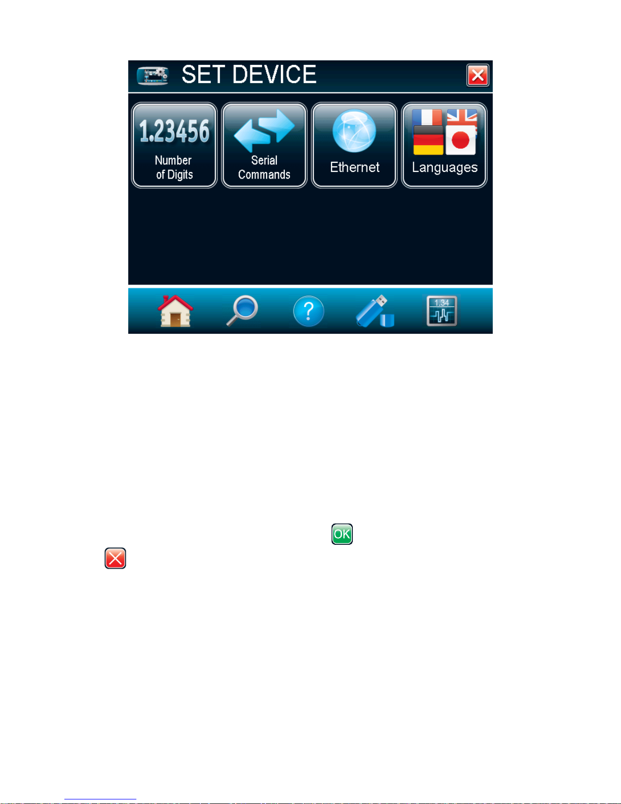
The Set Device lets you set and save the MAESTRO with customized parameters. You can set the time
and date of the device (not yet available), set the displayed significant digit, set the serial commands,
configure the Ethernet, and set the language (English, French, German, or Japanese). To exit the device
settings window touch the exit button or select any other option from the navigation bar at the
bottom of the window.
Fig. 2-5 The HOME menu window
Page 22
MAESTRO User’s Manual Revision 8.0 21
Fig. 2-6 The Set Device menu window
2.4.1.1 Date & Time (Not available on this version, check our web site for new versions)
The Date & Time button adjusts the time and date of the monitor's internal clock. This information is used
to timestamp files when you are logging data.
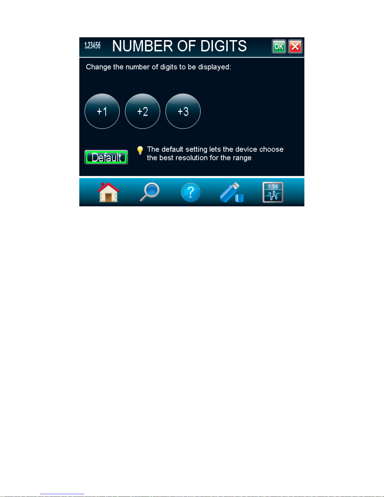
2.4.1.2 Number of Digits
To set the significant figures of the numerically displayed value, touch the Number of Digits button. You
will be able to choose the precision of 3, 4, or 5 digits. You can also choose the default settings, which
will let the device choose the best resolution to fit the scale. Absolute accuracy depends on the head.
When the number of digits is set, touch the OK button to save the changes or touch the cancel
button to ignore the changes.
Page 23
MAESTRO User’s Manual Revision 8.0 22
Power V Range
output
Fig. 2-7 The Number of digits menu window
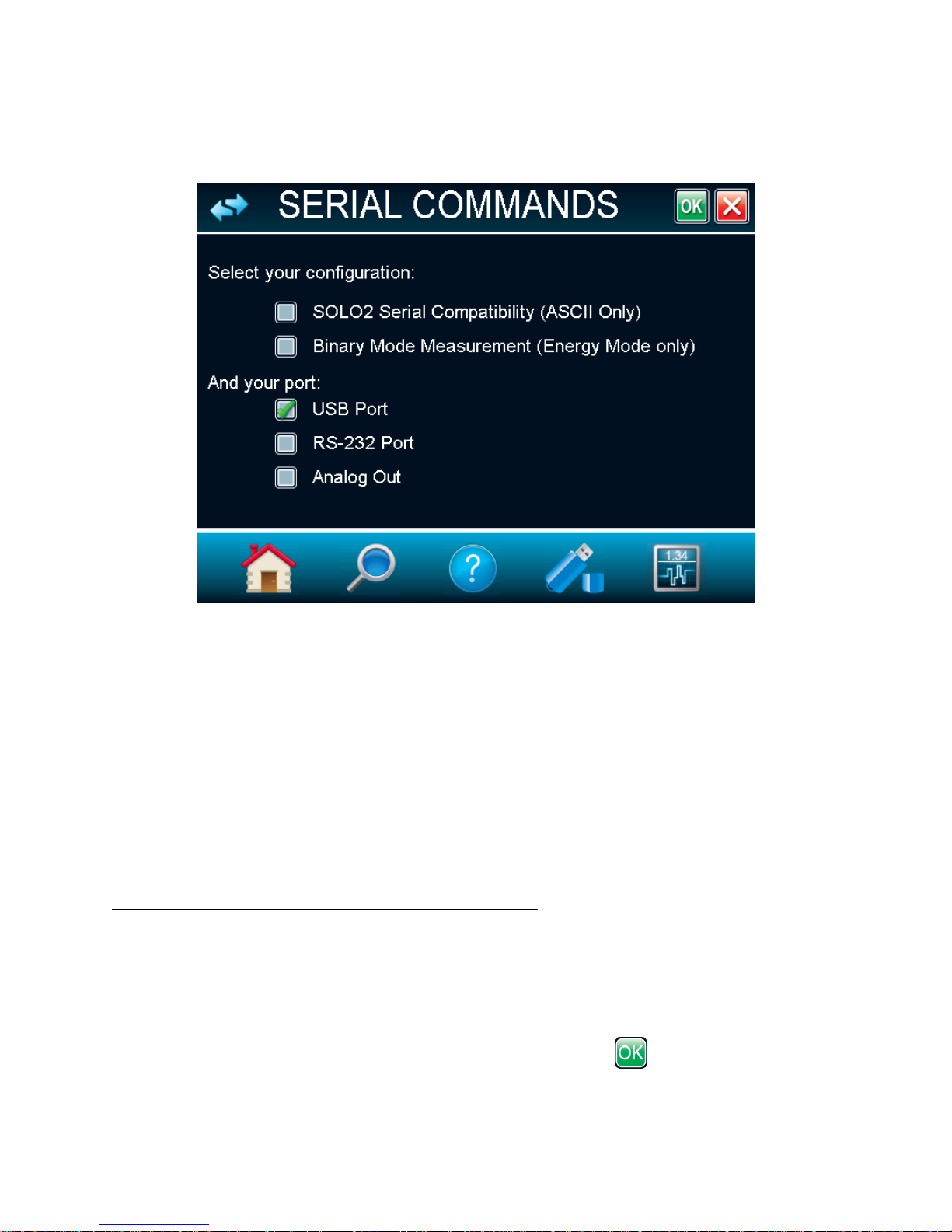
2.4.1.3 Serial Commands
The Serial Commands Menu allows you to configure the serial communication and input/output port
settings. Refer to section 3.4.3 for the complete serial commands directory. All the settings in this menu
are automatically saved, which means that at each reboot, the last changed settings will be loaded.
In order to ease the integration of the MAESTRO with setups using our legacy monitors, select SOLO2
Serial Compatibility. Note that only the ASCII commands are available. This feature is only available
when using the USB port for serial communication. Refer to section 3.4.4 for more information about the
available SOLO2 commands.
For fast data acquisition in energy mode, select Serial Binary Measurement. Refer to section 3.4.2 for
more information on how to use the MAESTRO’s serial binary measurement mode.
The serial communication can be done via USB port or RS-232 port. To use the RS-232 port, you must
use the special cable (part number 201860). Before using the serial communication after it was changed,
you must reboot the MAESTRO.
To use the analog output using the special cable (part number 201958), select Analog Output. The
MAESTRO will not need to be rebooted. This output allows the monitoring of the laser’s average power or
energy with external equipment such as a chart recorder, a computer with an analog interface, a
voltmeter, etc. In the case of a power measurement, the output signal represents the amplified and
anticipated power detector response. In the case of an energy measurement, the output signal is a DC
voltage representing the pulse energy value. In order to improve the signal to noise ratio, the 1 volt value
corresponds to the full scale reading of the selected range. The measured power or energy is then
related to the output voltage and to the selected range according to the following equations:
Page 24
MAESTRO User’s Manual Revision 8.0 23
Energy V Range
output
For example, an output of 0.4 volts on the 30 W scale corresponds to 12 watts of laser power. If on the
10 W scale, then 0.4 volts is equivalent to 4 watts.
Fig. 2-8 Serial Commands menu window
2.4.1.4 Ethernet
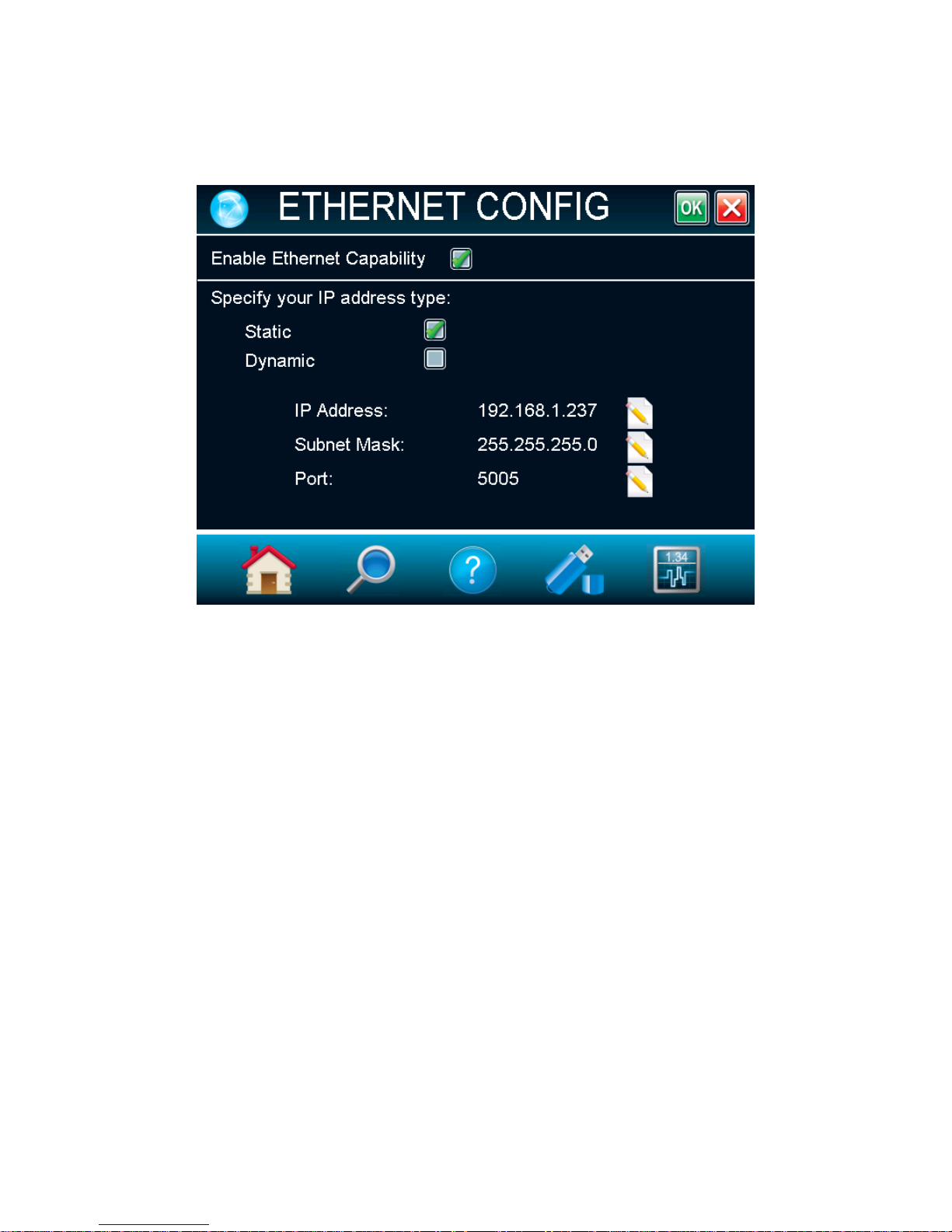
The MAESTRO allows the user to remotely control and acquire data. To configure the Ethernet settings,
touch the Ethernet button.
By default, the Ethernet capability is disabled, check the box to enable it. Note that enabling the Ethernet
port may increase the noise of the device if used without an Ethernet cable. You must always reboot the
MAESTRO after changing the Ethernet settings.
The Maestro runs TCP server applications. It can assign static or dynamic IP addresses. It is
recommended to use a dynamic IP address for most applications in order to prevent problems on your
network. When using a static IP address, please make sure you enter valid and available IP address.
Always ask your IT specialist for an available IP address. This will prevent conflicts and problems on
your network. If you are not sure which IP address to use, please use the dynamic IP address type, which
will automatically assign an available address.
Before booting the MAESTRO, connect it to a network cable. Boot the MAESTRO and access the
Ethernet Configuration Menu via Home / Set Device. Enable the Ethernet capability. You can choose to
specify a static IP address and enter your own IP address, or you can choose a dynamic IP address and
the server will automatically assign an IP address to the MAESTRO. If needed, you can change the port
number. When you are done with the setup, simply touch the OK button and reboot the MAESTRO.
If the address type was set to dynamic, access the Ethernet Config menu to retrieve the assigned IP
address.
Page 25
MAESTRO User’s Manual Revision 8.0 24
The device can now be accessed with a simple TCP client application, such as HyperTerminal. Only
native MAESTRO commands are supported with the Ethernet communication. Please make sure that the
SOLO2 Serial Compatibility is unchecked in the Serial commands menu (refer to section 2.4.1.3). Please
refer to section 3.2 for installation instruction on the PC.
Fig. 2-9 Ethernet Configuration menu window
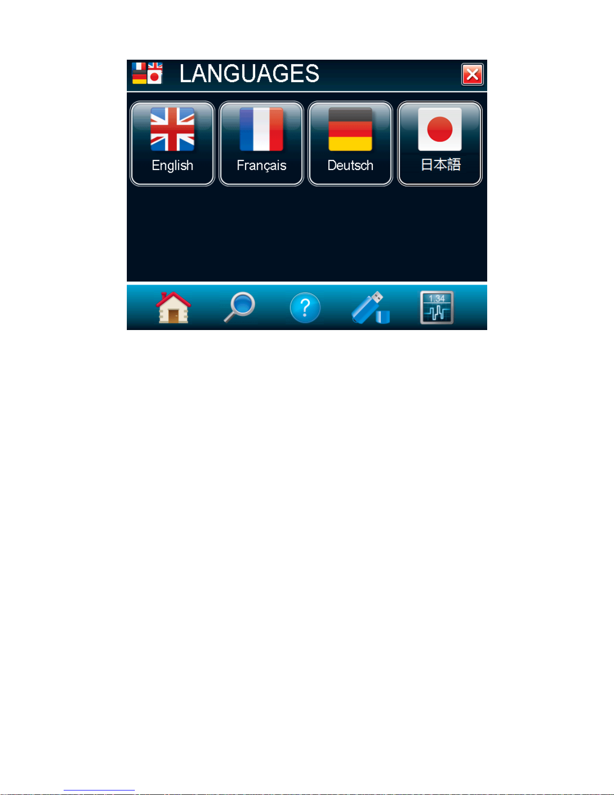
2.4.1.5 Languages
The Maestro allows the user to choose between an English, French, German, or Japanese display.
Chinese will also be available in the future. Check Gentec-EO’s website for updates.
Page 26
MAESTRO User’s Manual Revision 8.0 25
Fig. 2-10 Language Configuration menu window
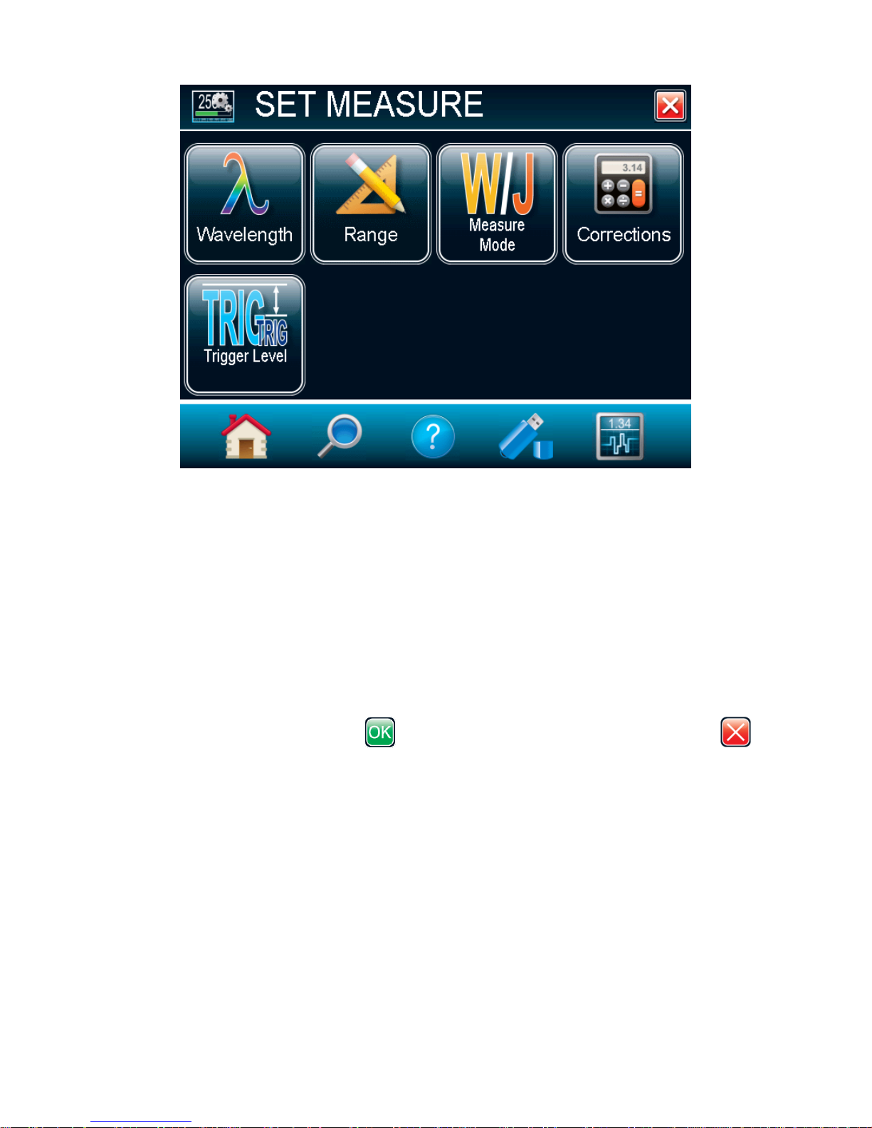
2.4.2 Set Measure
Options in the Set Measure menu define user-adjustable measured data parameters. The Wavelength
can be changed in order to set it to the wavelength at which the detector is used. The power or energy
Range allows you to adjust the scale in order to obtain the best possible resolution. Correction factors
that will affect the reading can be easily programmed. They can be used for a beam sampler, attenuator,
or other optics that require you to multiply and/or add offsets to the detector reading. Trigger Level and
Measure Mode are also found in the Set Measure menu.
Page 27
MAESTRO User’s Manual Revision 8.0 26
Fig. 2-11 The Set Measure menu window
2.4.2.1 Wavelength
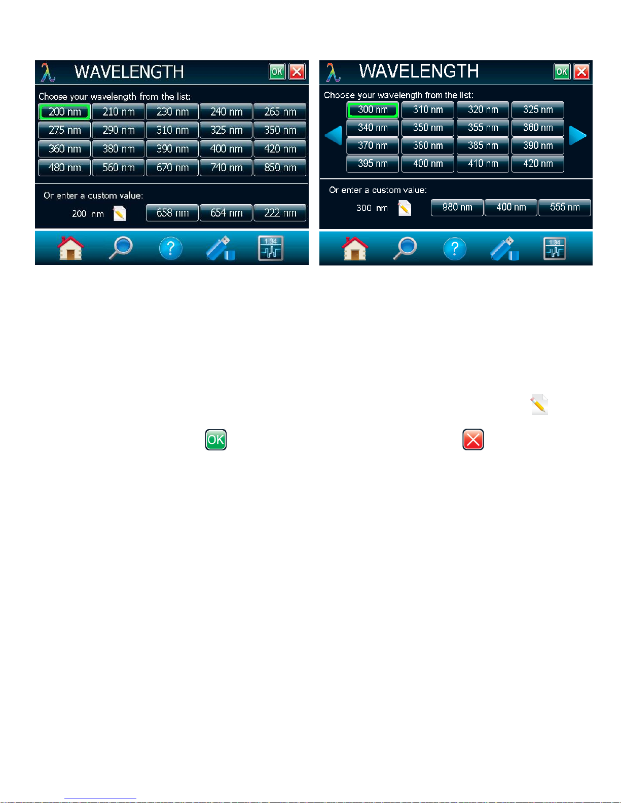
The Wavelength menu is used to select the proper wavelength at which the detector is used. It applies a
correction to adjust for the variation in responsivity at different wavelengths. Pre-programmed
wavelength correction factors dedicated to each detector head are available and automatically loaded
from the detector EEPROM, for version 5 and higher detector heads. When a new detector is plugged in,
the calibration wavelength is the default selection.
To change the wavelength, select the appropriate wavelength from the Wavelength menu. For
photodiodes, left and right arrows will allow you to access all the available wavelengths. Once the
wavelength is set, touch the OK button to save the changes or touch the cancel button to
ignore the changes.
Page 28
MAESTRO User’s Manual Revision 8.0 27
Fig. 2-12 The Wavelength menu windows
The MAESTRO automatically recognizes the latest energy and power detector for accurate autocalibration. More importantly, it takes advantage of our Personal wavelength correction™: it reads the
memory in the Smart Interface connector to provide a wavelength correction based on spectral data
measured from that specific detector. Your measurements across the band have never been this precise
or easy.
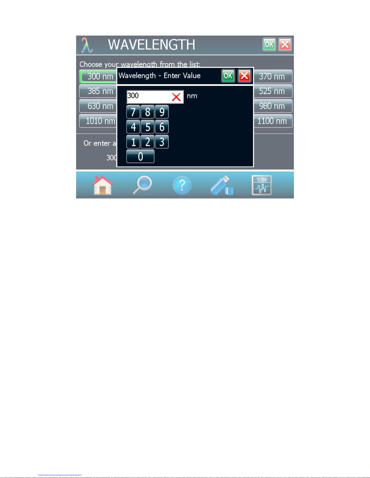
You can also adjust for a wavelength other than the preset wavelength. The MAESTRO will use the preprogrammed data in the detector’s EEPROM. When working at such a wavelength, it will not be available
in the Wavelength menu; you must manually enter the desired wavelength by touching the edit
button. A popup window menu will appear prompting you to enter the wavelength. When the wavelength
is set, touch the OK button to save the changes, or touch the cancel button to ignore the
changes. The MAESTRO only allows you to choose values that fall within the detector’s range. If you
enter an invalid value, a menu pops up to signal the error and the MAESTRO automatically selects the
default value, which is the wavelength used for calibration at Gentec-EO during manufacturing or
subsequent service.
Page 29
MAESTRO User’s Manual Revision 8.0 28
Fig. 2-13 Popup window to enter a user defined wavelength
Once you have entered a new wavelength in the MAESTRO, you can save your settings (refer to section
2.4.5).
2.4.2.2 Range
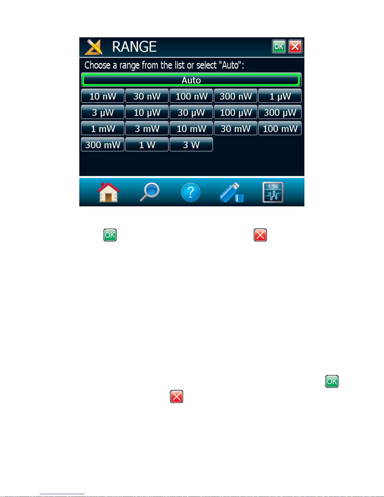
The Range menu window is used to select the signal level read by a detector head. When a new head is
plugged in, the auto mode is the default option. In this condition, the MAESTRO automatically selects the
best range for the value being measured. You can also choose a fixed scale according to the specific
connected detector head. The MAESTRO only shows range values that fall within the detector head’s
range. You can only choose from these available ranges
Page 30
MAESTRO User’s Manual Revision 8.0 29
Fig. 2-14 The Range selection menu window
To change the range, simply touch a range value from the appropriate range. When the range is set,
touch the OK button to save the changes, or touch the cancel button to ignore the changes.
When in a manually selected range, you should always use the next higher range to the measured value,
for maximum precision.
Special care must be taken in the case of widely varying pulse energy to ensure that every pulse is
detected. Contrary to the case of a power measurement where the auto mode adjusts continuously to the
measured value, the auto mode in energy mode bases its range selection on the energy of the previous
pulse. A pulse with energy less than 2% of the current scale will not be detected. Always set the scale to
the best one available. To be sure to measure lower energies, set the scale manually to the lowest level
and set the autoscale, the MAESTRO will autoscale to the best scale. In this case, the pulses that
saturated the scale while the autoscale was searching for the best scale will be invalid.
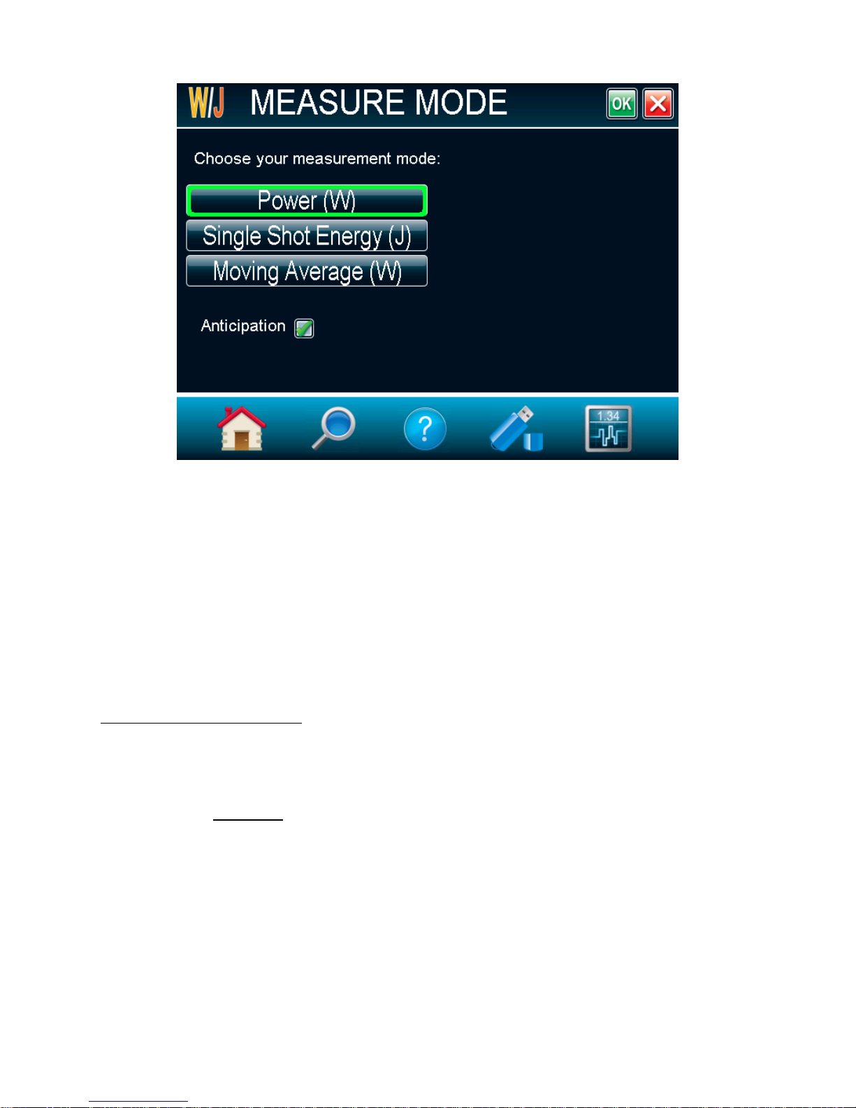
2.4.2.3 Measure Mode
Depending on the type of detector head connected on the MAESTRO, you can choose different measure
modes. The following figure shows an example of the measure mode menu window when a thermopile
detector head is connected to the MAESTRO. Once the measure mode is set, touch the OK button
to save changes, or touch the cancel button to ignore the changes.
Page 31
MAESTRO User’s Manual Revision 8.0 30
7
Delay
Rep. Rate
1
Fig. 2-15 The Measure mode selection menu window for a thermopile detector head
Depending on the type of detector head connected to the MAESTRO, you will have different choices for
the measure modes.
For thermopiles, you have the following measure modes:
Power in Watts (default);
Single Shot Energy in Joules7: (Energy mode/ calorimeter mode);
Moving Average in Watts.
This function allows you to measure the energy contained in a laser pulse with a Gentec-EO power
detector head. This mode of operation gives access to the same options as in the case of an energy
pyroelectric joulemeter. The only restriction is that the time delay between
pulses,
user manual for the specific power detector you are using.)
You must select the range manually because the autoscale is deactivated when you select Energy
Mode.
Keep in mind that the power detectors are optimized to sustain high average power, not high peak
energy. Always keep the energy density below the maximum energy density quoted in the manual for
that specific detector.
The energy mode is always available for power detectors with a typical sensitivity value. A precision of
±3% in the pulse energy measurement can be achieved if the power detector head is specifically
calibrated in energy mode. Please contact your local Gentec-EO distributor or nearest Gentec-EO office
for more information on obtaining a pulse energy measurement calibration.
, must be compatible with the detector specification. (Please refer to the
Page 32

MAESTRO User’s Manual Revision 8.0 31
For photo detectors, you have the following measure modes:
Power in Watts (default);
Moving Average in Watts;
Power in dBm (dBm = Log [power in Watts/0.001W]).
For Pyroelectrics
Energy in Joules (default);
Average Power in Watts.
Energy Dose in Joules(Not available on this version, check our website for new versions);
Moving Average in Joules (Not available on this version, check our website for new versions).
When selecting the Moving Average option for thermopiles or photo detectors, or the Average Power
option for the pyroelectrics, a popup window will appear to select the averaging period. This will
automatically turn on the statistics in continuous mode. Please do not turn off the statistics nor change to
non-continuous mode to continue using the Moving Average, or the Average Power options. Also note
that if an acquisition is done while the MAESTRO is in one of these modes, the saved data will also be in
the same format.
The Moving Average is available for those head types:
Thermopile
Photodiode
Pyroelectrics head that work in average power (radiometer)
The Average Power is available for those head types:
Pyroelectrics
Photodiode configured in Energy mode.
Uncheck Anticipation to deactivate the power meter acceleration software that provides accelerated
response. By using advanced algorithms and known properties of the detector, this software allows the
MAESTRO to provide a very accurate power measurement a few seconds faster than the natural
response of a thermopile power detector. It accelerates the natural response by a factor of 5 to 10.
Turning off the anticipation will result in a slower response but will reduce the noise level and provide a
more stable measured value in a noisy environment.
Version 7 energy heads have been calibrated with and without the attenuator at a chosen wavelength.
When enabling the attenuator, only the wavelength at which it has been calibrated will be available in the
wavelength menu. Similarly photodiodes have been calibrated with and without the attenuator at
chosen wavelengths. When enabling the attenuator and touching the OK button , the MAESTRO
Page 33
MAESTRO User’s Manual Revision 8.0 32
will prompt the wavelength menu because the available wavelengths with and without the attenuator are
different.
A checkmark shows when the anticipation or attenuator is activated. It is a toggle switch - select it to
change between on and off. For the anticipation, the default is on and for the attenuator, the default is off.
However, these defaults can be changed in the startup config menu (refer to section 2.4.5).
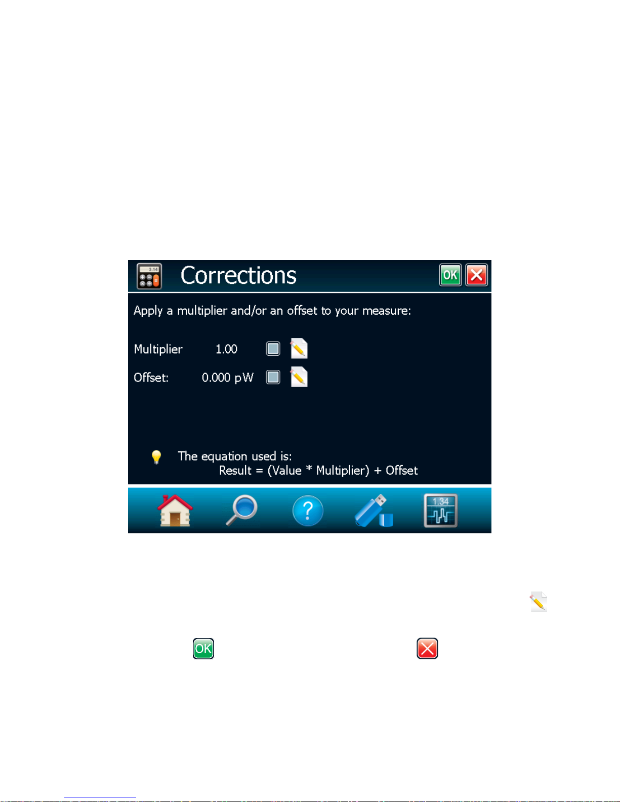
2.4.2.4 Corrections
The user can apply a multiplier and an offset value to the detector reading. Correction factors are most
useful when sampling a percentage of a powerful laser beam or correcting for absorption along an optical
chain. The menu displays the values of the correction factors that are being applied to the
measurements.
The default value for the multipliers is 1, and the default for the offset is 0. To activate the correction
factors, touch Corrections in the Measurement Settings menu and then select Multiplier or Offset by
touching the appropriate check box. To change the multiplier or the offset’s value, touch the edit
button. A dialog box opens where you can enter the correction value. This number will be multiplied with,
or added to the actual measured value, to calculate the corrected value. Once the correction values are
set, touch the OK button to save the changes or the cancel button to ignore the changes.
The MAESTRO will then display the corrected value.
For example, if you are measuring the laser beam passing through the 99.9% back reflector of a laser
(giving 1/1000th of the real value), choose Multiplier and enter 1000 in the dialog box. The MAESTRO
will display the laser’s power rather than the measured 0.1% sample on the main display.
Fig. 2-16 Setting Correction menu
Page 34
MAESTRO User’s Manual Revision 8.0 33
It is essential to make sure that the actual measured value also complies with the power and energy limits
of the detector head. The auto range option is the default selection. You can select a specific range but
it must always be based on the actual physical measured values and not on the corrected value. Of
course, the displayed values and the display scale selection are then calculated to take into account the
correction factors.
Note that the Statistics are computed for the corrected values only.
To disable the correction factor, touch the check box corresponding to the correction factor (multiplier or
offset) in the Corrections menu window.
2.4.2.5 Trigger Level
The trigger level only functions if an energy detector head is connected or if a power detector head is
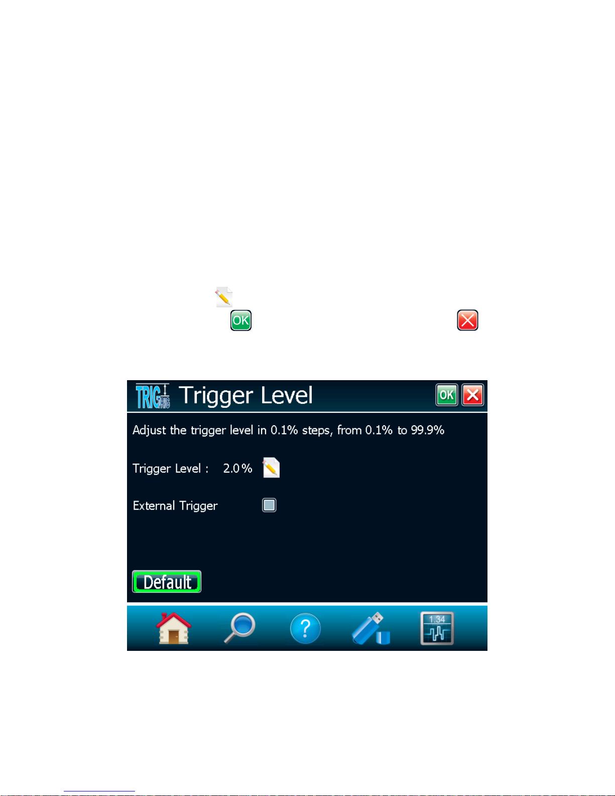
used in Pulse Energy (Calorimeter) mode. This option allows you to change the Trigger Level from 2%
of the full-scale default value. This proves to be especially useful in noisy environments. Acceptable
values range from 0.1% to 99.9% with 0.1% steps. Caution should be taken when choosing a lower
trigger level than the 2% default value in a high noise environment.
To change the trigger level value, access the menu window by selecting Trigger Level from the Set
Measure menu. Touch the edit button and enter the desired number in percentage. Once the trigger
level is set, touch the OK button to save the changes or the cancel button to ignore the
changes. The MAESTRO will not detect pulses with a value under the trigger level. Be careful to select a
scale that is close to the measured value, if the trigger level is high. To reset the default value to 2.0%,
simply touch the Default button.
Caution! If you select a high value trigger level, the MAESTRO may not be able to detect all the values
of widely varying energy levels in auto range mode. The auto range function uses the energy level of
the last pulse to set the scale level. Therefore, it will not detect the next pulses if they are lower than the
Fig. 2-17 Trigger Level window
Page 35

MAESTRO User’s Manual Revision 8.0 34
trigger level. As a result, the auto range may become caught on a high scale value. To avoid this
problem, select a lower value for the trigger level, change the scale manually, or reset the auto range
mode by reselecting auto in the Range menu (section 2.4.2.2).
Erratic triggering?
In electrically noisy environments, it is possible that the MAESTRO will inadvertently trigger on
the noise. If this is the case, increase the trigger level to 3% or higher if necessary.
It is always good practice to reduce electrical noise generation or shield the detector and
monitor when measuring very low pulse energies.
You can also set the MAESTRO to be triggered externally, via the RS-232 port using a special cable (part
number 201956). Just touch the External Trigger check box.
2.4.3 Display
The various displays offered by the MAESTRO allow you to quickly view measurements in several
different ways. You will appreciate the easy-to-view high resolution, color graphic in dual or full-screen
mode on the 112.9 x 84.7 mm LCD display. You can choose five different display modes:
Real Time
Scope
Needle
Averaging
Histogram (Not available on this version, check our website for new versions).
Statistics
This allows you to select the best way to display measurements according to your specific needs. You
can switch from one option to another without interfering with the measurements.
Page 36
MAESTRO User’s Manual Revision 8.0 35
Fig. 2-18 Display menu window
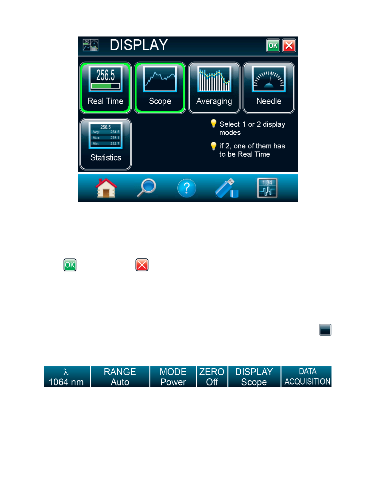
The MAESTRO allows you to have a single full-screen display or a dual-screen display. To select the
desired display touch the appropriate button. If you choose dual display, one of the displays must be Real
Time. Select Real Time, then select any other display mode by touching it. To return to single display
mode, simply touch the unwanted display mode to cancel it. Once the selection is made, touch the OK
button or the cancel button to ignore the changes.
The MAESTRO’s default mode is dual Real Time and Scope display (Figure 2-1).
2.4.3.1 Display Parameters menu bar
The full-screen display fills the entire window, hiding the navigation menu bar. The Display Parameters
menu bar is at the bottom of the window to allow you to quickly view and access different settings. To
retrieve the navigation menu bar, switch to the dual screen display mode by touching the Minimize
button. In the dual-screen display mode, the Display Parameters menu bar is located under the Real
Time display (see figure 2-1).
Fig. 2-19 The Display Parameters menu bar
The current display settings are easily changed by touching the desired parameter in this menu. Touch
anywhere on the screen to deselect the setting.
Page 37
MAESTRO User’s Manual Revision 8.0 36
Option
Icon
Description
Wavelength
()
Sets and displays the source’s
wavelength.
If the desired wavelength is not on
display, touch More…, which will take
you to the Wavelength menu window
(refer to section 2.4.2.1). The wavelength
value tells you what NIST-based
calibration factor is active. You can find
the factors on the Calibration and the
Personal wavelength correction™
certificates that are shipped with your
detector.
Range
Sets and displays the detector’s range.
Touch Auto to be in auto range mode, +
to increase the range, and – to decrease
the range.
Touch More… to go to the Range menu
window (refer to section 2.4.2.2).
Mode
Sets and displays the Measure Mode
depending on the connected detector
head. Quickly access all the detector
head’s available measure modes using
this button. For more information, refer to
section 2.4.2.3.
Zero
Resets the zero reading level. It does
this by subtracting the power reading on
the display as soon as the On button is
touched. Subsequent measurements will
be relative to this zero power level. The
main purpose of this option is to remove
reading offset caused by thermal noise in
the environment. Thermal noise is
caused by a detector that has not been
thermally stabilized OR there was a heat
source in the field of view of the detector
when the MAESTRO was turned on (for
example, the hand or body of the user).
Use this function once your power meter
has achieved thermal equilibrium to
ensure accurate measurements.
For instructions on the proper way to
adjust your detector’s offset to zero see
step 8 in Section 2.2 Quick power and
energy measurement procedure.
In Energy mode the zero clears the
current value.
Table 2-3 List of Display Parameters menu bar options
Page 38
MAESTRO User’s Manual Revision 8.0 37
Display
Sets and displays the monitor’s display
mode. You can choose between the
following displays:
Real Time
Scope
Needle
Averaging
Histogram (Not available on this
version)
Statistics
In the dual-screen mode, it corresponds
to the bottom display. For more
information, refer to section 2.4.3.
DATA
Acquisition
Lets you start, stop, and configure the
data acquisition on a connected USB key
at any time. Touch Start to start the
acquisition on the USB key and touch
Stop to stop before the end of the total
duration of the acquisition. Touch
Configure to access the Acquisition
menu window (refer to section 2.4.4),
which will allow you to set the acquisition
parameters.
Page 39
MAESTRO User’s Manual Revision 8.0 38
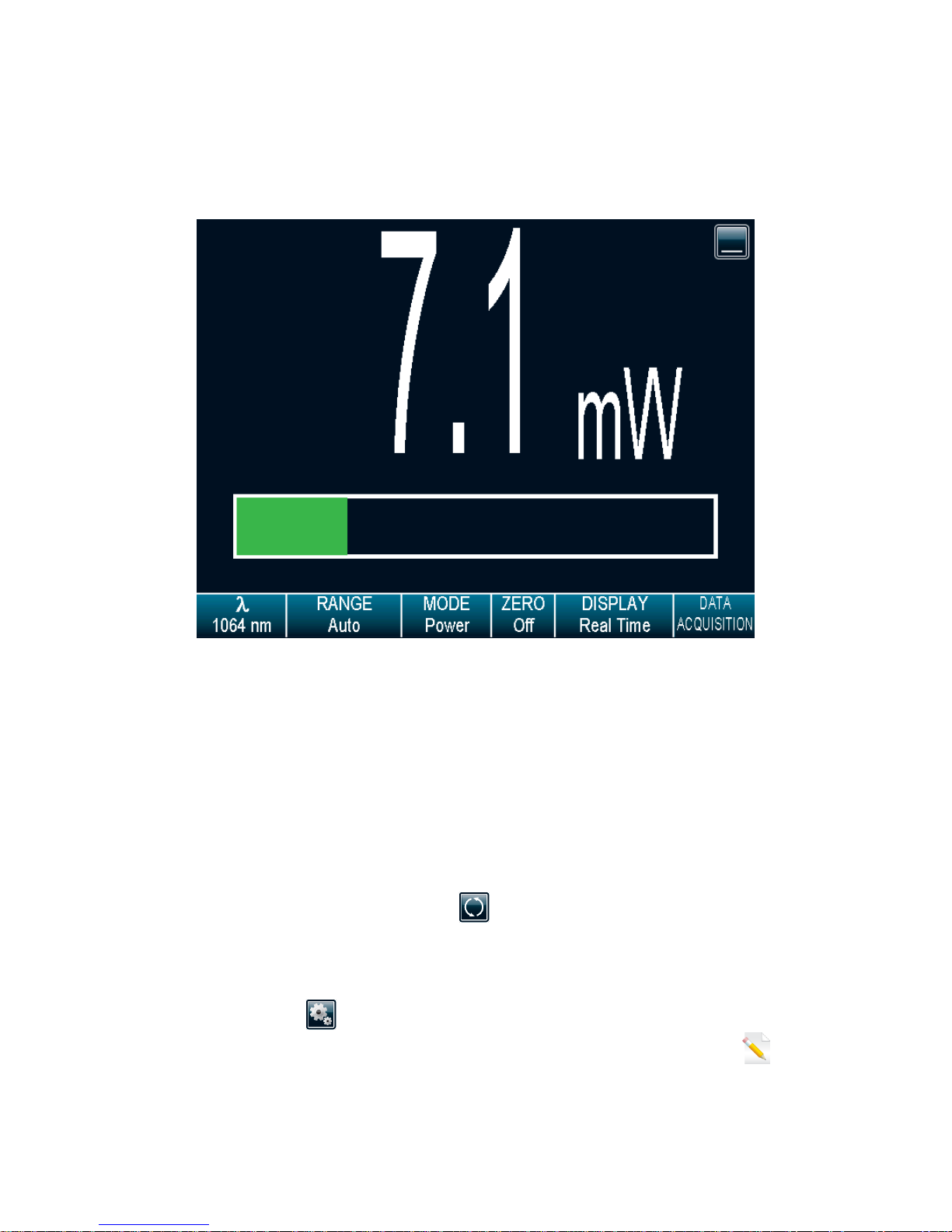
2.4.3.2 Real time display
The Power or Energy digital display is presented in giant format for easy reading in all conditions.
Directly below it, as wide as the screen, is the Bar graph display, which presents the measurement in
analog format; very useful for rapidly varying values.
Fig. 2-20 Real time display
With a MAESTRO, you can also choose between the high resolution mode for the most significant digits
available or the standard resolution, to filter out unimportant fluctuations in measurement. You can adjust
the number of digits in the Set Device menu window accessible through the HOME menu
(section2.4.1.2).
2.4.3.3 Scope display
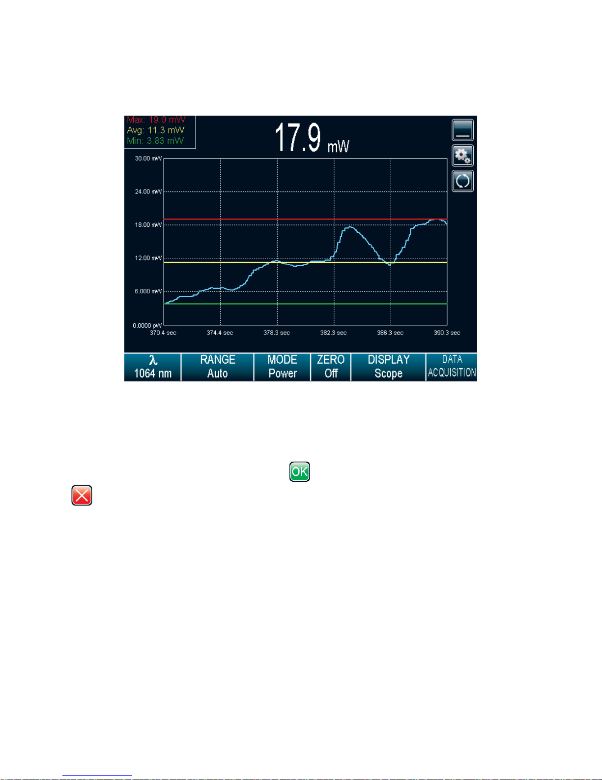
The Scope display gives a quick look at the laser beam’s long-term stability and trend as a function of
time. The current data is also displayed at the top of the graphic display.
To refresh the scope touch the refresh button . The graphic will be erased before new data is
displayed. This is useful when an out of range value has been measured.
Touch the Settings button to access the Scope settings. This will allow you to change the X-Axis
scale, the Y-Axis scale (not available), and to display the statistics. Just touch the edit button to
change the X-Axis and Y-Axis scale (not available). For the X-Axis value, enter the desired display time
period. In case you enter an incorrect value, an error popup menu will prompt you to change it to a valid
Page 40
MAESTRO User’s Manual Revision 8.0 39
value. To view the maximum, minimum, and average values of the measured data (in wattmeter mode
only), touch the Display Stats check box.
Fig. 2-21 Scope time display
Display Stats. When using the single full-screen mode, this will display the maximum, minimum, and
average values of the measured data values in the upper left corner.(available only in wattmeter mode on
this version, check our web site for new versions). The graphic yellow line will correspond to the
maximum value, the green line to the average value, and the red line to the minimum value. When the
scope parameters are set, touch the OK button to save the changes or touch the cancel button
to ignore the changes.
Page 41
MAESTRO User’s Manual Revision 8.0 40
2.4.3.4 Needle display
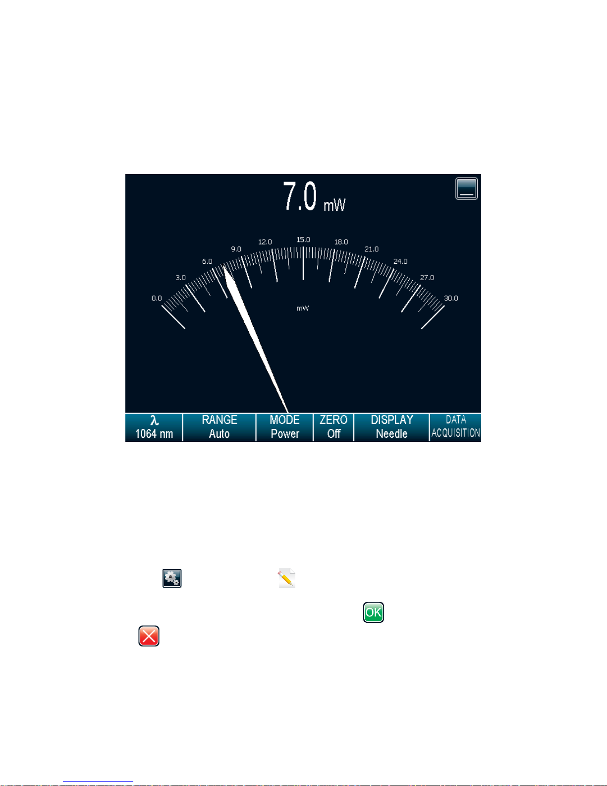
When you select the Needle, a graphical interface shows a real-time digital needle. The deflection of the
digital needle is proportional to the real-time measurement. The 0 is on the left-hand side of the needle,
whereas the range’s maximum value is on the right-hand side of the needle.. The numerical value of the
real-time measurement is also displayed above the digital needle. The 15 Hz refresh rate makes it an
excellent tool for laser tuning and alignment.
Fig. 2-22 Digital needle display
2.4.3.5 Averaging display
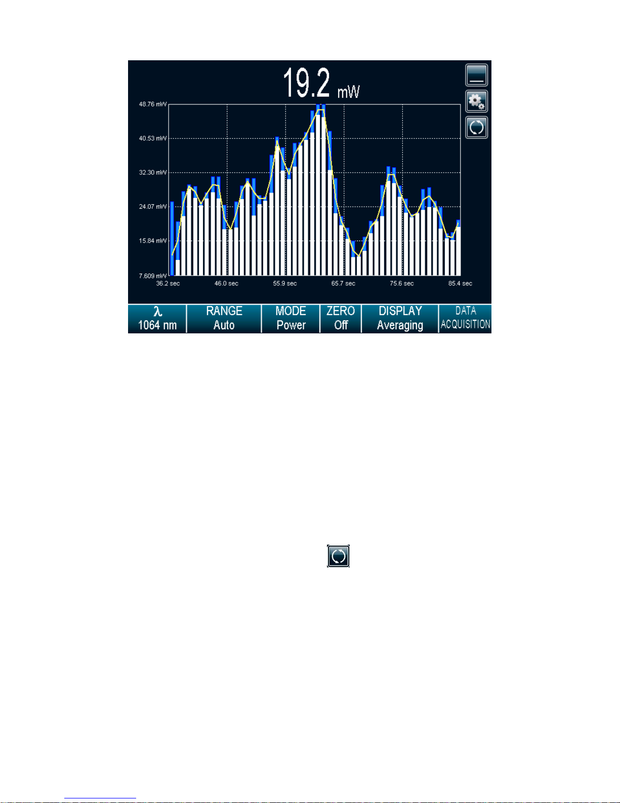
The averaging display is a bar graph that presents the statistics of a set of measures as a function of
time. The MAESTRO measures a series of data during a user-defined period of time. Each bar
represents the maximum, average, and minimum values of the measured data. The top of the white bar
represents the minimum value while the top of the blue bar represents the maximum value. The yellow
line represents the average value for each set of bars. This allows you to quickly evaluate the trends of
the average, maximum, and minimum values in time. You can change the sampling period by touching
the Settings button . Just touch the edit button to change the period, in seconds. If you enter
an incorrect value, an error popup window will prompt you to change it to a valid value between 1 and 120
seconds. When the averaging period is set, touch the OK button to save the changes or touch the
cancel button to ignore the changes. Statistics always run in the background in this mode. This
mode is a real time average of a group of data defined in the data sampling setting.
Page 42
MAESTRO User’s Manual Revision 8.0 41
Fig. 2-23 Averaging display
For Power Detectors:
In the Averaging display mode, the power measurement is the average value defined in the
averaging settings. For optimum averaging, when measuring the average power of a pulsing
laser, it is preferable to use a sample period that is a multiple of your laser repetition rate. For
instance, if you are running at 1 Hz, use an average period of 1, 2, 3 etc… seconds. If it is at 1.5
Hz, use 3, 6, 9 etc… seconds, as the sample period. Take note that if one data point is out of the
current scale, the resulting period average will be OUT. You should set the scale higher than
your maximum unfiltered measurement to avoid this situation.
For Energy Detectors and Power Detectors in Energy Mode:
In the Averaging display mode, the Energy measurement is the average value defined in the
averaging settings.
To refresh the graphic, touch the refresh button . The bars will be erased before new data is
displayed. This is useful when an out of range value has been measured.
Page 43
MAESTRO User’s Manual Revision 8.0 42
2.4.3.6 Statistics display
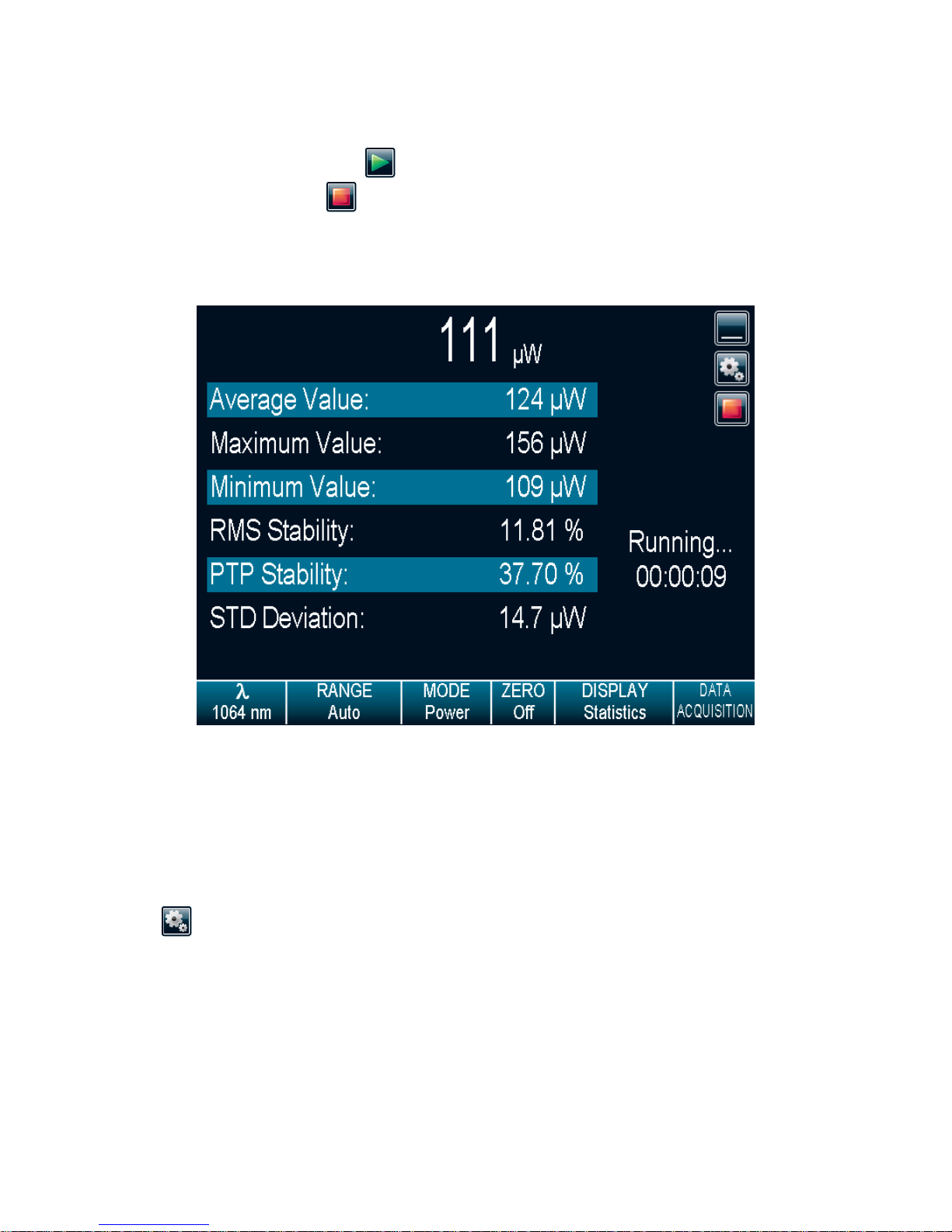
In the Statistics mode, the MAESTRO displays a complete statistical analysis of power or energy
measurements. Touch the PLAY button to start or restart the data sampling and statistical
calculations. Touch the Stop button to stop the data sampling and statistics before you reach the
end of the selected sampling time. The last statistical values calculated remain on screen so you can
view them later, even if you switch display modes and return to the Statistics display. The data sampling
and statistical calculations continue with this window closed or opened, and no matter what display you
select.
Fig. 2-24 Statistics display
The values in this display provide an additional digit of resolution to allow you to benefit from the
improved precision of large samples. You must understand your sample size well enough to know if this
additional digit is significant.
The MAESTRO uses default sample parameters unless you set them yourself. Touch the Settings
button to access the Statistics Settings to set up the data sampling parameters for calculating the
statistics. Use the defaults or select your own duration sample period to do the statistics.
You can also decide to save only the statistics instead of the entire acquisition or the entire acquisition
followed by the statistics at the end of the file. To do so, check the Save to File option and configure the
output filename (refer to section 2.4.4 Acquisition). If you want to save only the statistics, press the Start
button in the Statistics mode. If you also want to save the entire acquisition and the statistics, touch the
DATA ACQUISITION button on the Display Parameters menu bar and then touch Start (refer to section
2.4.4). In this case, note that the sample rate will only affect the acquisition as the sample rate for the
Page 44
MAESTRO User’s Manual Revision 8.0 43
8
statistics is fixed8. Furthermore, if the acquisition is stopped before the end of the acquisition duration, the
statistics will not be saved to the output file.
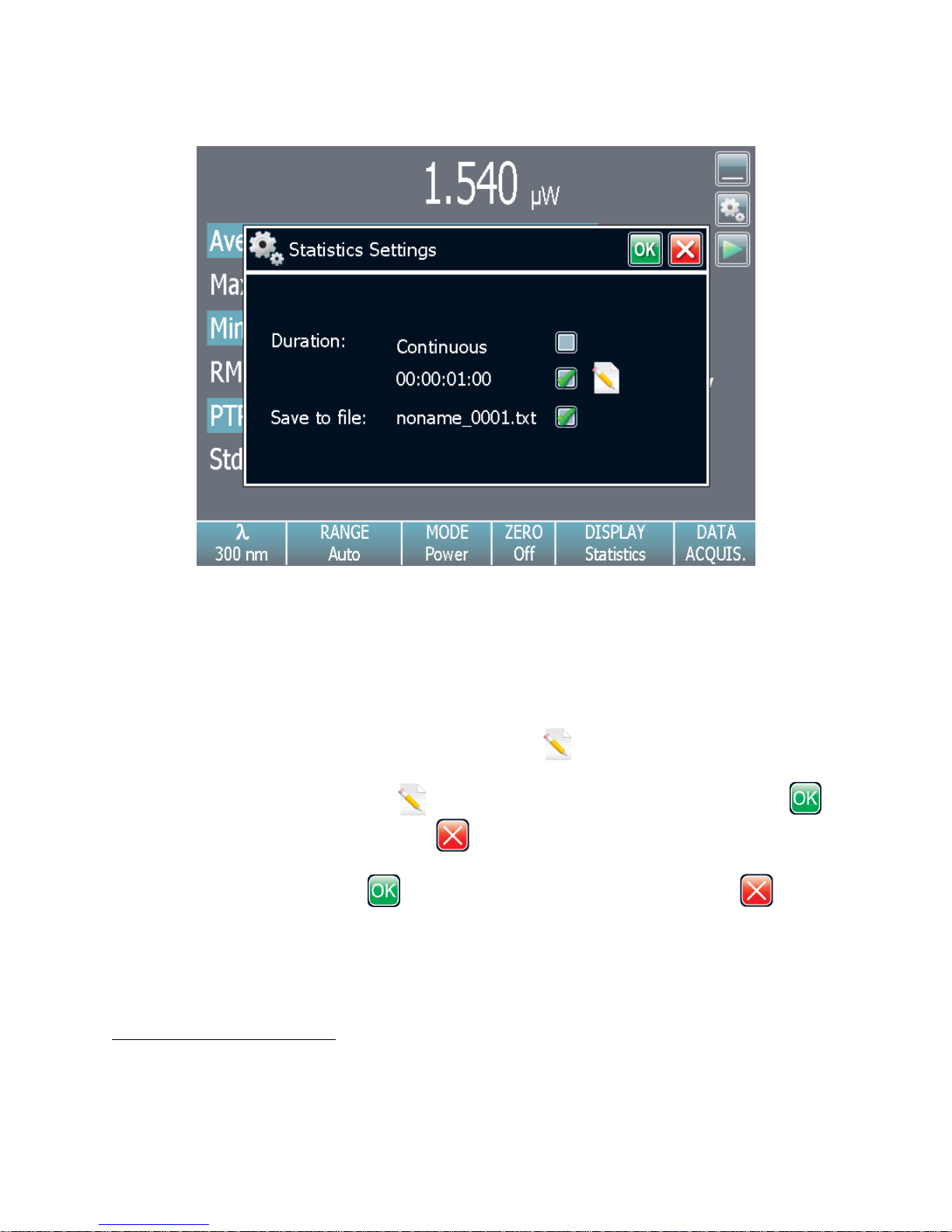
Fig. 2-25 Statistics settings popup window
You can set the MAESTRO either to calculate the statistics for a single sample and stop, or to repeat
continuously. Take data for a few seconds or a few days. You have the flexibility to handle any
application, from analyzing a single short pulse with high resolution to sampling performance over a
period of months.
You can choose to compute the statistical analysis continuously, which is the default option, or to
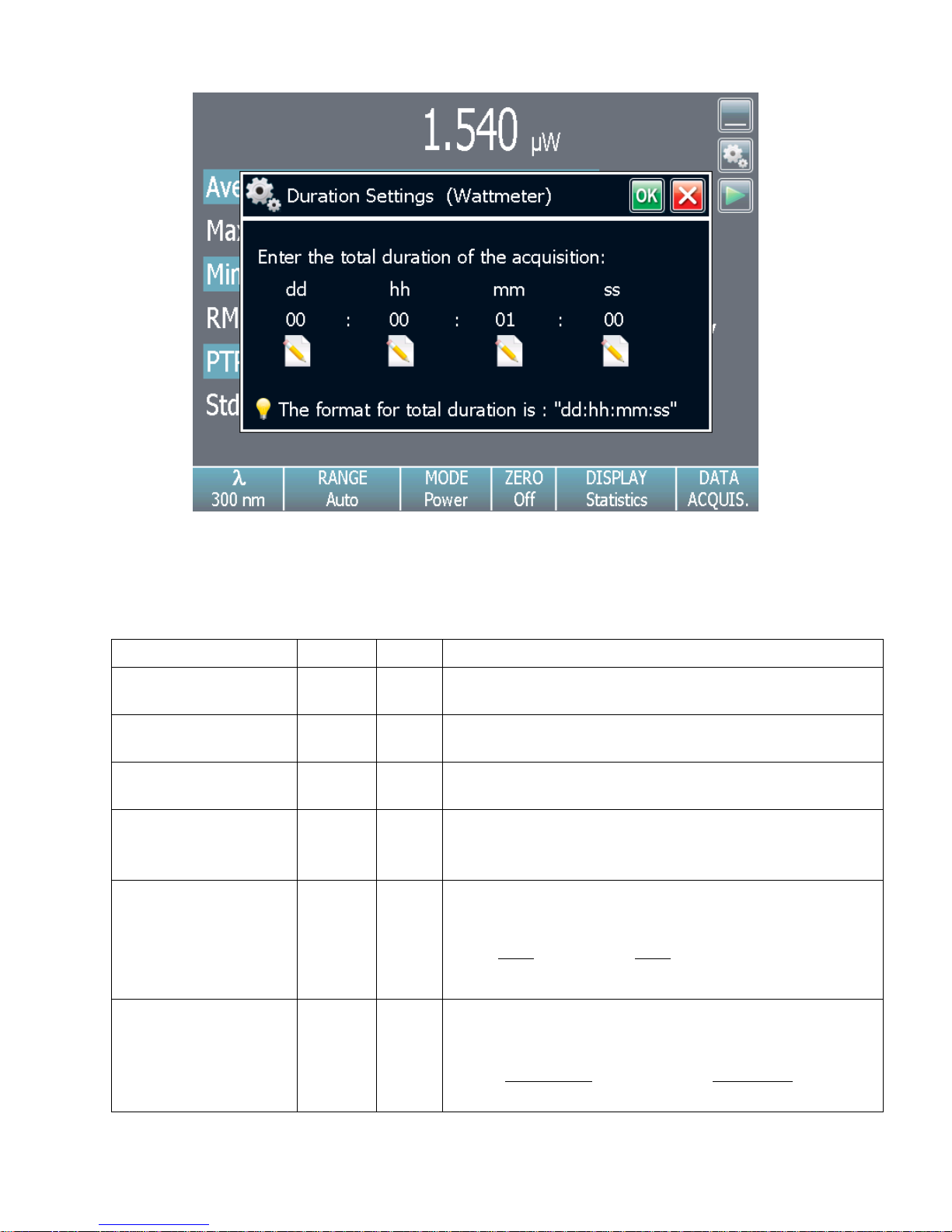
compute it only during a specific time interval. Touch the edit button for the duration in the statistics
settings popup window to display the statistics duration settings popup window. To change the total
duration of the acquisition, touch the edit button under each time value. Touch the OK button to
save the changes or touch the cancel button to ignore the changes. The format of the duration is
dd:hh:mm:ss, which correspond to days, followed by hours, minutes and seconds. When the total
duration is set, touch the OK button to save the changes or touch the cancel button to ignore
the changes.
The MAESTRO automatically clears and recalculates the statistics at the end of each sample period
unless you manually stop it.
The sample rate for the statistics is fixed at 12.302 Hz for power detectors and 1 pulse per pulse for
energy detectors.
Page 45
MAESTRO User’s Manual Revision 8.0 44
Statistical Parameters
Power
Energy
Definition
Current value
Value of the most recent measurement
Average value
Average from the start of values in the sample, E
avg
or P
avg
Maximum value
Highest value in the sample period, E
max
or P
max
Minimum value
Lowest value in the sample period, E
min
or P
min
RMS stability
Root mean square stability represents the standard deviation
as a percentage of the average.
100
avgE
STD
RMS
,
100
avgP
STD
RMS
PTP Stability
Shows the spread between the highest and lowest point in the
sample as a percent.
100
minmax
avg
E
EE
PTP
,
100
minmax
avg
P
PP
PTP
Fig. 2-26 Statistics duration settings popup window
The statistical parameters that are calculated are listed in Table 2.4.
Table 2.4. Statistical Parameters
Page 46
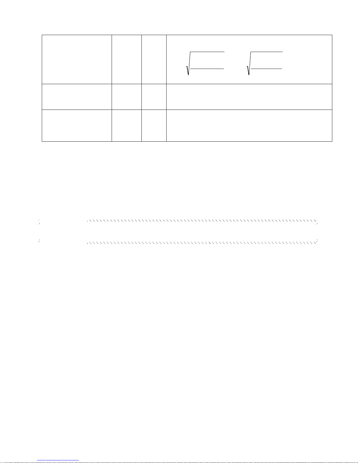
MAESTRO User’s Manual Revision 8.0 45
STD Deviation
(only available for the
single full-screen mode)
A measure of the spread of the data around the average.
1
1
2
n
EE
STD
n
i
avgi
,
1
1
2
n
PP
STD
n
i
avgi
Repetition Rate
(only available for the
single full-screen mode)
Frequency of pulses coming from the laser, PRR
Average Power
(only available for the
single full-screen mode)
Power calculated from the pulse energies and repetition rate.
PRREP avgavg
Sample Rate
Controls how fast you collect data.
Eg. 10 points/second or 50% of the pulses
Total Duration
Controls how long the MAESTRO will
acquire data and/or do statistics.
Eg. 1 period, 5 hours or 1000 pulses
2.4.4 Acquisition
The MAESTRO allows you to easily acquire data and save it on a USB key for post analysis and
processing. If you did not connect a USB key to the MAESTRO, the monitor will prompt an error
message and the acquisition option will not be available.
You have complete control over the data sampling. The key points to remember whether using a
joulemeter or wattmeter are:
Page 47
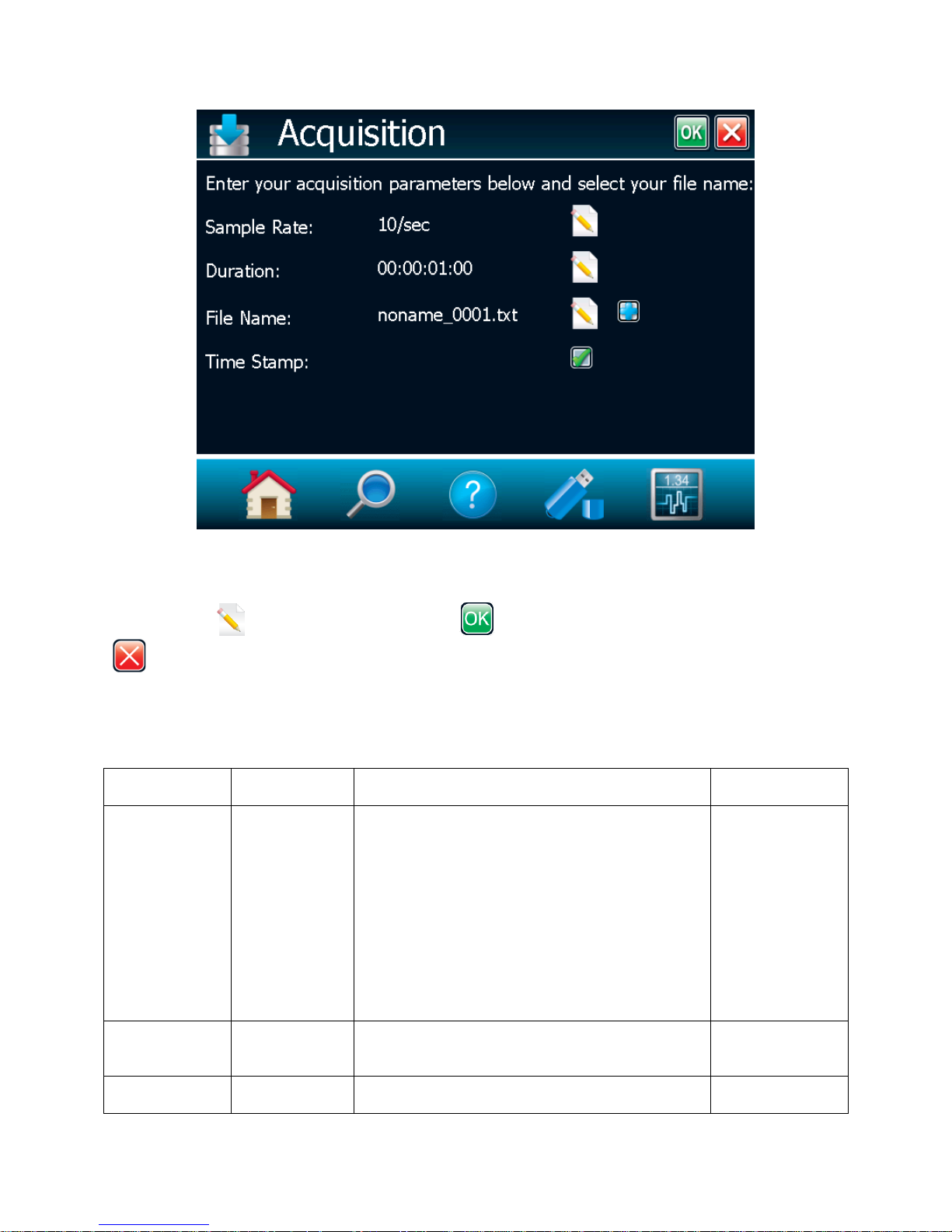
MAESTRO User’s Manual Revision 8.0 46
PARAMETER
Choices
Description
Default
Sample Rate
Power only
Integers
pts/Second
pts/Minute
pts/Hour
pts/Day
Current setting is 10 samples per seconds.
Sets the time between each sample. Specify the
number of points per unit of time. [for example,
for 1 second between samples, set to 60 points
per minute].
Next, you must set the time period for the
number of points entered.
Maximum is 10 points/second,
Minimum is 1 point/day.
Time between samples = 1/(sample rate).
10 per sec
Sample Rate
Energy only
Integers
1/x pulses
Sets the fraction (1/x pulses) of the incoming
pulses sampled for the statistics calculations and
data recording.
1/1 pulses of the
incoming pulses
Duration
Time format
The time period for which samples are reported
(to the display and output). The format of the
1 minute
Fig. 2-27 Data sampling parameters window menu.
The different available options are presented in Table 2.5. To edit one of the data sampling parameters,
touch the edit button. Touch the OK button to save the changes or touch the cancel button
to ignore the changes.
Table 2.5 Data Acquisition Parameters
Page 48
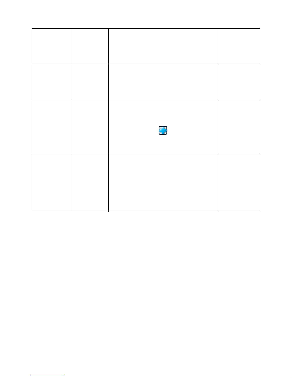
MAESTRO User’s Manual Revision 8.0 47
Power only
dd:hh:mm:ss
00:00:00:00
duration is dd: hh:mm:ss, which correspond to
days, followed by hours, minutes and seconds.
The MAESTRO automatically clears and
recalculates the statistics at the end of each
sample period unless you manually stop it.
Duration
Energy only
Integers
Number of
pulses
Number of pulses for which samples are reported
(to the display and output).
The MAESTRO automatically clears and
recalculates the statistics at the end of each
sample period unless you manually stop it.
10000 pulses
File name
Alphanumeric
characters
Output file
name
Use the displayed keyboard to enter the new
output file name with an extension (.csv, .txt or
.dat). Note that you must enter a file name to be
able to start an acquisition.
Use the Add button to increment the file
name. If no name was entered, the Add button
automatically adds a file name.
noname_0001.txt
Time Stamp
Yes
No
To have a time stamp appear with the data,
touch the associated check box.
Selecting the check box writes a time stamp with
each data point. This is a relative time stamp that
always begins with zero.
Note that, with the time stamp, the maximum
sampling rate without missing points is 1.3 kHz
instead of 2 kHz without time stamp.
No
To start the acquisition you must return to the display window in dual or single mode. Touch the DATA
ACQUISITION button on the Display Parameters menu bar and then touch Start (refer to section
2.4.3.1). The MAESTRO begins storing data according to your Data Sampling settings. The Stop
command stops the data recording before the end of the acquisition total duration. Even if the acquisition
is stopped, the MAESTRO will continue to provide measurements to the display. If you want to be able to
open the file in Excel use .csv in your file name extension.
Page 49
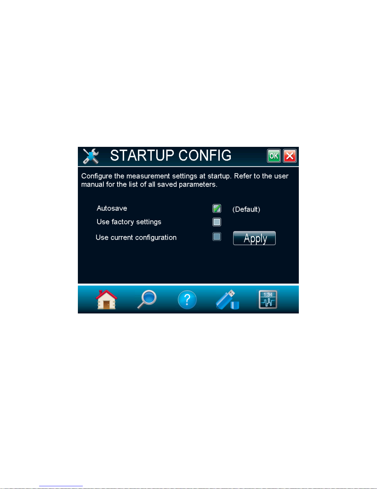
MAESTRO User’s Manual Revision 8.0 48
2.4.5 Startup Config
The MAESTRO can be configured to store and load certain settings for a specific measurement head in
the Startup Config Menu. By default, the MAESTRO will always remember the last saved settings and
load them at startup (Autosave).
To load factory settings at startup, select Use factory settings. Note that selecting this option will not
change the current configuration, but will only load the factory settings at the next reboot.
It is also possible to save a specific configuration. To do so, change all the desired settings and return to
the Startup Config Menu. Touch the Apply button. The Use current configuration check box will be
selected and the MAESTRO’s current configure will be saved. Even if the settings are changed after this
operation, these changes will not be saved and at startup the MAESTRO will be configured in the same
manner as when the Apply button was touched.
These are the saved parameters:
Range;
Anticipation (on or off);
Attenuation (on or off);
Wavelength;
Multiplier and Offset;
Trigger level;
Acquisition sample rate;
Acquisition and statistics duration
Acquisition time stamp (on or off);
Save statistics to file (on or off).
Measure Mode (Power, Single Shot Energy, dBm, Energy)
Display (Scope, Needle, Statistics)
Fig. 2-28 Startup Config menu window
Page 50
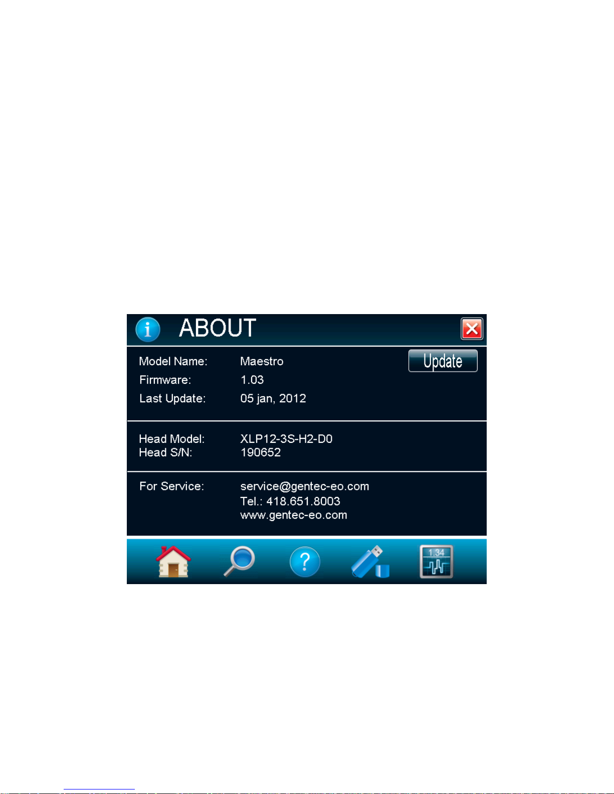
MAESTRO User’s Manual Revision 8.0 49
If another head is connected, it will not be able to retrieve these saved parameters since they are head
specific: these parameters can be loaded only if the same type of head is connected to the MAESTRO.
The following settings are always saved automatically on the MAESTRO, regardless of the head that is
connected:
Serial Commands settings
Ethernet Configuration
Language
2.4.6 About
The About button in the Home menu displays any help and service information available for this version
of the MAESTRO firmware. You can find all the information about the monitor and the connected
detector head such as:
The monitor’s model name (MAESTRO);
The monitor’s firmware version;
The monitor’s last update;
The connected detector head’s model name;
The connected detector head’s serial number.
You can also find all the information concerning Gentec-EO for service support. If you should need help
or additional information on the MAESTRO or any Gentec-EO products, do not hesitate to contact us. We
will be glad to help you.
Fig. 2-29 About window.
Page 51
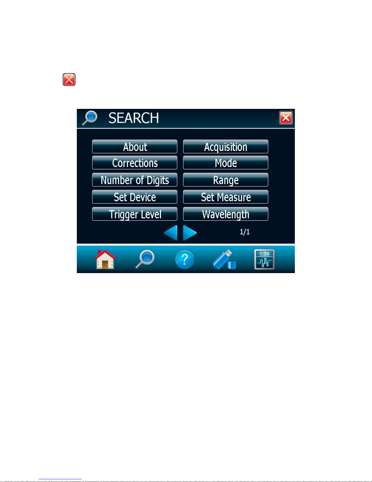
MAESTRO User’s Manual Revision 8.0 50
2.5 SEARCH
The SEARCH option allows you to quickly look up and find the most common of the MAESTRO’s
functions. The functions are displayed in alphabetical order. Just touch one of the displayed functions to
directly access the corresponding menu window. To exit the SEARCH window, just touch the cancel
button .
Fig. 2-30 Search window.
Page 52
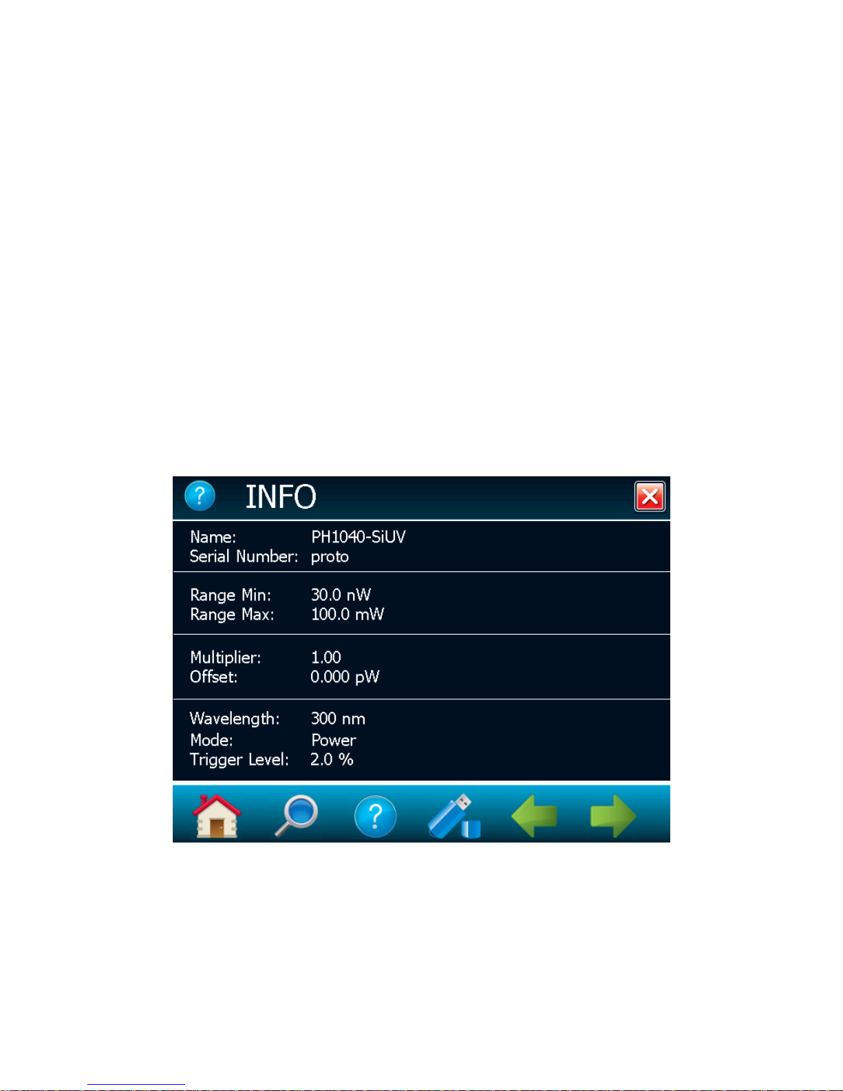
MAESTRO User’s Manual Revision 8.0 51
2.6 INFO
The Information menu window displays the information about the detector head connected to the
MAESTRO and the current measurement settings. In a quick glance you will be able to see the following
information:
Information about the connector detector head:
o The detector’s Name;
o The detector’s Serial Number;
o The detector’s minimum and maximum Range.
Information about the measurement settings (refer to section 2.4.2):
o Correction factors (multiplier and offset);
o Wavelength;
o Measure mode;
o Trigger Level.
Fig. 2-31 Information menu window
Page 53
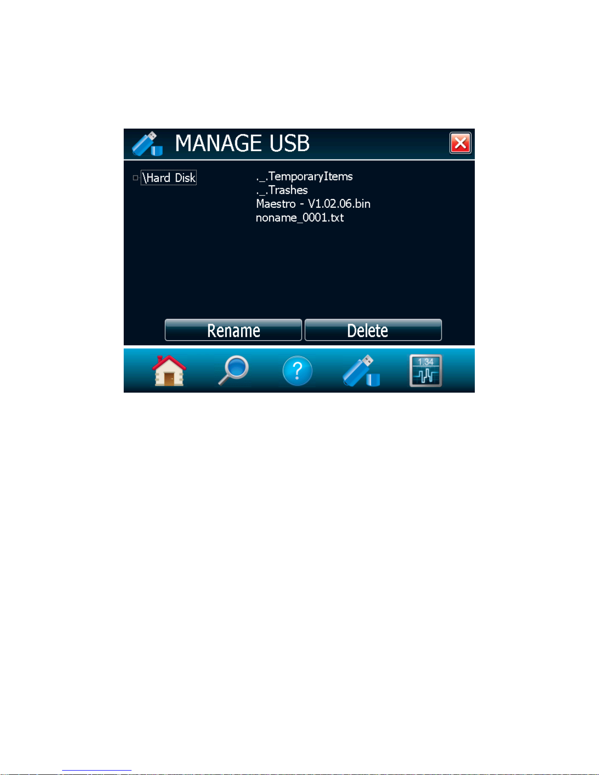
MAESTRO User’s Manual Revision 8.0 52
2.7 MANAGE USB
The MANAGE USB is a file manager, which lets you work with the file system on the connected USB key.
You can easily view the folders and files already on the USB key in an intuitive hierarchy. You can also,
rename a file and delete a file. This allows you to have full control over the USB key for easy acquisition.
Fig. 2-32 Manage USB menu window
You can scroll up and down the list by sliding your finger on the right hand side of the screen. You can
also collapse the USB key’s tree structure by touching the small square next to “\Hard Disk”. By doing so,
you will have access to different folders on your USB key.
2.8 BACK TO MEASURE BUTTON
The “Back to Measure” button allows the user to easily return to the current measurement window. It will
return to the user’s last selected display option. For instance, if the user was in Needle display, touching
the “Back to Measure” button will return to the Needle display.
Page 54

MAESTRO User’s Manual Revision 8.0 53
3 SERIAL COMMUNICATION INTERFACE
3.1 USB Serial Communication
3.1.1 Installation
Connect the MAESTRO USB port, located on the front panel of the instrument (see Figure 1-2), to the
host device serial connector using the proper cable. The MAESTRO comes with a standard USB cable.
3.1.1.1 Installation for Windows™:
Plug the MAESTRO into a USB port on the PC. If the PC supports USB 1.1, Windows will detect the new
device and prompt you for the software drivers. A Found New Hardware – USB Device window will open
and, after several seconds to a minute, the Found New Hardware Wizard will appear.
Insert the USB drivers CD-ROM if not done already.
For Windows XP, Vista or 7: Cancel the wizard and execute the Auto installer “USB driver installer-r2” in
the USB Driver folder from the CD-ROM.
At the end of this process, a new serial COM port will be added to the list of communication ports. It may
be used as any other serial port. See the Installation PDF to verify or change the COM port assignment.
You will need to know the COM port number to set up the serial connection to the MAESTRO.
3.1.2 Setting up Communication to the MAESTRO
3.1.2.1 Verify COM Port
To verify the USB installation and find the COM port number, click:
Start → Settings → Control Panel → System → Device Manager
Scroll down to Ports (COM & LPT) and double click that line. One of the options should be
USB-to-Serial Port (COM#)
Note the COM port number. You need it for the next step.
3.1.2.2 Connect to the MAESTRO
You may use any serial communications software that you are familiar with. Our instructions are for
HyperTerminal because it is widely available on PCs with Windows. Select:
Start → Programs → Accessories → Communications → HyperTerminal
To save communication settings, enter a name for the connection. In the drop down menu for “Connect
using” select the COM port that the USB driver was installed on (Section 3.1.2.1). Select OK.
Input the following settings into the communications parameter window that appears next.
Page 55

MAESTRO User’s Manual Revision 8.0 54
Bits per second
115,200
Data bits
8
Parity
None
Stop bits
1
Flow control
None
Click OK to begin entering serial commands in the HyperTerminal window.
3.1.2.3 To echo commands
The commands you type will not appear in the HyperTerminal window, unless you setup the
HyperTerminal to do so. Only the response from the MAESTRO will be displayed. If you prefer to see
the commands you are typing, on the HyperTerminal window click the File menu and execute the
following sequence:
File → Properties → Settings (tab) → ASCII setup → select “Echo typed characters locally” → OK
3.1.2.4 Test the connection
In the HyperTerminal window, type *VER. If the response you receive tells you the version of your
MAESTRO, you are successfully connected and ready for serial command action.
3.1.2.5 HyperTerminal settings shortcut
When you end the session, HyperTerminal asks if you want to save your settings. To avoid inputting the
communication parameters again in the future, save by clicking Yes. The next time you execute the
string of commands, the name of your session will appear after HyperTerminal. Clicking on the session
name will open the connection using the saved settings. To avoid re-entering the string of commands,
put a shortcut to this file on your desktop:
Search for the file name. Select the file. Right click and select Shortcut in the drop down menu.
Page 56

MAESTRO User’s Manual Revision 8.0 55
3.2 Ethernet Communication
The MAESTRO Ethernet communication is based on Transmission Control Protocol (TCP). Through a
well configured channel, the user will be able to send commands and receive a response from the device.
Gentec-EO provides an application to help users communicate with the MAESTRO via Ethernet
communication. You can download the MAESTRO Ethernet Communication Example application in the
Gentec-EO software download section or in the Gentec-EO Labview driver download section.
You must enter the right configuration:
1. Plug the MAESTRO to a network cable;
2. Boot the MAESTRO;
3. Open the MAESTRO Ethernet Configuration menu (HOME | SET DEVICE | ETHERNET)
4. Check “Enable Ethernet Capability”;
5. Choose your IP address type (Static or Dynamic);
6. If the address type is static, enter a valid and available IP address. Always make sure the IP
address is available to avoid any conflicts in your network. Always ask your IT specialist for an
available IP address or use the ping command followed by the desired IP address in the
Windows’ cmd application to make sure the address is available;
7. Change the communication port if necessary;
8. Touch the OK button
9. Reboot the device;
10. Open the MAESTRO Ethernet Communication Example application on your PC;
11. Enter the MAESTRO’s IP address and port number. If the address type is dynamic, return to the
Ethernet Configuration page to retrieve the assigned address;
12. Click on the Connect button in the MAESTRO Ethernet Communication Example application;
13. A popup will ask if you want to start a continuous reading. If you choose yes, the command *CAU
will be automatically sent to the MAESTRO and the you will start to receive data from the device;
14. You can send other commands to the MAESTRO using the Command edit box and the Send
button. Note that only native MAESTRO serial commands are valid with Ethernet communication.
Please make sure the SOLO2 Serial Compatibility check box is disabled in the Serial
Commands menu.
Page 57
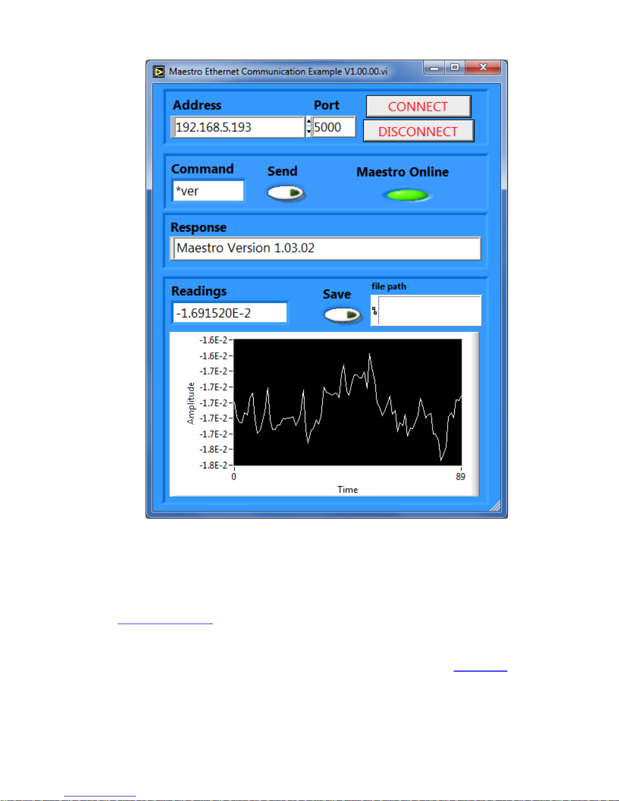
MAESTRO User’s Manual Revision 8.0 56
Fig. 3-1 MAESTRO Ethernet Communication Example application
3.3 PC-MAESTRO user-friendly serial data acquisition software
User-friendly communication software specially made for the MAESTRO is available for free through our
website (www.gentec-eo.com). This software basically transforms your PC screen into a large
MAESTRO screen enabling you to control and see your information from a distance, while saving data.
LabView™ drivers are also available to let you customize MAESTRO applications on your PC.
You can download the PC-MAESTRO program. Access our website and go to the Downloads section.
Click on the file name and download it to your PC. The specific actions necessary vary by browser and
browser settings. After it is transferred, open the file on your PC and follow the instructions to
decompress and install it.
Page 58

MAESTRO User’s Manual Revision 8.0 57
The user manual is integrated in the PC-MAESTRO’s interface. The Context Help window displays basic
information about the PC-MAESTRO’s functionalities when you move the cursor over each object and
button. You can display the Context Help window by selecting Help/Show Context Help in the menu bar
or by pressing the <Ctrl-H> keys.
If you try to install the same PC-MAESTRO version twice on your computer, you will have the following
warning:
Installation Summary:
No software will be installed or removed.
In such a case, please press enter and continue using the installed version of PC-MAESTRO.
When disconnecting a head on the MAESTRO while using PC-MAESTRO, the PC-MAESTRO might not
see the disconnection and might continue to try to read data. In such a case, please close and restart the
application.
3.4 Traditional Communication Settings
The traditional serial communication interface also allows you to operate the MAESTRO from a remote
location. We recommend using the specific serial data acquisition software PCMAESTRO, if no
automated acquisition is involved because it is much easier to use. In the case of automated
measurement controlled by other software, use the following commands to control the MAESTRO. They
are divided into two groups:
The control commands allow you to change the MAESTRO’s settings without using the
MAESTRO’s touch screen. Remote control commands do not yield any data, they only confirm that
the command has been executed.
The acquisition commands are used to obtain information on the current status of the MAESTRO.
They do not change the MAESTRO’s settings, they return the requested information.
3.4.1 Serial Command format
3.4.1.1 Serial Protocol Rules:
Commands are sent as text strings. The response will either be data or an empty string.
3.4.1.2 Text mode rules:
All text commands must begin with a trig character (*). You do not need to end with a line-feed, a
carriage-return, or both. Parameters must NOT be separated by any spaces. Characters do not have to
be capitals, mixed upper and lower case is ok. Replies to all text mode commands are also in text mode,
and end with a carriage-return and line-feed.
In case of an error, the reply string is in the following format:
Error X: reason [enter]
X is the error code, and reason is an explanation. See Error Codes at the end of this section.
Because all Text Mode replies end with a carriage return <CR> or line-feed <LF> (or both), a text reply
contains tabulations when many elements need to be separated in the string. This is useful when
exporting data to a spreadsheet.
Page 59

MAESTRO User’s Manual Revision 8.0 58
O Y X X X X X
X
O X X X X X X
X
3.4.2 MAESTRO Binary Mode Description
3.4.2.1 Description
The MAESTRO has two Communication Modes: the Binary Mode for FAST data acquisition and the
ASCII mode. The resolution is 14 bits for both cases.
Only the joulemeters support the binary mode. Thermopiles in energy mode, thermal heads in standard
mode and photodiodes are coded in ASCII. To select the binary mode select Home/Set Device/Serial
Commands/ Serial Binary Measurement. If you wish the MAESTRO to remember this setting, touch the
Set as Default button.
The value in binary mode is coded in two bytes.
Binary Joulemeter MODE
Byte #1
Byte #2
B = The sign.
Y = The MSB for the Wattmeter Mode.
X = Bits of the Codification.
FOR ALL MODES
O = Order
0 = First byte (MSB)
1 = Second Byte
3.4.2.2 Codification
Measurement in Joule = Current Scale *Value in Decimal/16382
Example 1:
For 151 mJ on the 300 mJ scale on Channel 1
The MAESTRO will send you: 40B6 HEX VALUE, where:
10 = 0 1000000
The first second bit (0) is the order of the MSB
1000000 is the MSB of the codification
9B =10110110
The first bit (1) is for the order so this is the LSB of the codification
The Total Codification is 10000000110110, which is 8246 in decimal (8246/16382 * 300mW =
151.007 mW)
The codification 11111111111111 = No connector
The codification 11111111111110 = OUT detected
Page 60

MAESTRO User’s Manual Revision 8.0 59
Command name
Command
Description
DISPLAY COMMANDS
Set Range
SCS
Manually set range.
Set Range Up
SSU
Change scale to the next higher range.
Set Range Down
SSD
Change scale to the next lower range.
Get Current Range Index
GCR
Returns scale index between 0 to 41
Get Autoscale
GAS
Returns autoscale status
Display Valid Scale
DVS
Displays the valid ranges for the connected detector head.
Set trigger level
STL
Set the internal trigger level when measuring pulse energy.
Get Trigger Level
GTL
Returns trigger level value
Get Mode Display
GMD
Returns the current display mode on MAESTRO
MEASUREMENT COMMANDS
MEASUREMENT DATA ACQUISITION
Query Current Value
CVU
Get the value currently displayed on the screen.
Download points
CAU
Send the values in ASCII to the serial port with the data sampling
setting.
Stop the CAU Command
CSU
Stop the CAU Command.
Query New Value Ready
NVU
Determine if new reading is available.
Set the autoscale
SAS
Set the autoscale.
Get the laser rep rate frequency
GRR
Send the value in ASCII to the serial port.
Set the joulemeter binary mode
SS1
Set the joulemeter binary mode or ASCII mode
Get Binary Joulemeter Mode
GBM
Returns binary joulemeter mode or ASCII mode
Set Analog Output
ANO
Enables or disables analog output
MEASUREMENT SETUP
Set Personal Wavelength Correction
PWC
Specify the wavelength.
Get Wavelength
GWL
Returns wavelength in nm
MEASUREMENT CONTROL
Set Anticipation
ANT
Turn anticipation on or off.
Get Anticipation status
GAN
Returns the anticipation status
Set Zero Offset
SOU
Zero the reading.
Clear Zero Offset
COU
Undo the zeroing of the reading.
Get Zero Offset
GZO
Returns zero offset status
Set diode Zero Offset
SDZ
Zero the reading for all scale’s for the photodiode.
Set User Multiplier
MUL
Set the value of the multiplier’s correction value.
Get User Multiplier
GUM
Returns the current multiplier’s correction value
Set User Offset
OFF
Set the value of the Offset correction value.
Get User Offset
GUO
Returns the current offset correction value
SET Single shot Energy mode
SSE
Set the Energy mode for the calorimeter mode.
Set attenuator
ATT
Set the attenuator.
Get Attenuator
GAT
Returns the attenuator status
INSTRUMENT AND DETECTOR INFORMATION COMMANDS
Query version
VER
Get firmware version of the monitor.
Query Status
STS
Retrieve detector information and monitor settings.
Query Extended Status
ST2
Returns extended status
3.4.3 Serial Command Directory
Page 61

MAESTRO User’s Manual Revision 8.0 60
The serial commands format is as such:
*MUL+ 8 character numeral value Ex: « *MUL1.000000 » or « *MUL-1.34e-3 » or «*MUL0.000543 »
*OFF + 8 character numeral value like above
*STL+4 character numeral value like « *STL10.2 » or « *STL0.22 »
*SSE1 / *SSE0 : Single Shoot Energy ON or OFF
*ATT1 / *ATT0: Attenuator ON / OFF (When available)
Page 62

MAESTRO User’s Manual Revision 8.0 61
Command
Parameters
Return
SCS
Range index
Range index
Range
00
1 picowatt or picojoule
01
3 picowatts or picojoules
02
10 picowatts or picojoules
03
30 picowatts or picojoules
04
100 picowatts or picojoules
05
300 picowatts or picojoules
06
1 nanowatt or nanojoule
07
3 nanowatts or nanojoules
08
10 nanowatts or nanojoules
09
30 nanowatts or nanojoules
10
100 nanowatts or nanojoules
11
300 nanowatts or nanojoules
12
1 microwatt or microjoule
13
3 microwatts or microjoules
14
10 microwatts or microjoules
3.4.3.1 Serial commands
SERIAL COMMAND FORMAT
All text commands must begin with a trig character (*) and DO NOT end with a line-feed or a
carriage-return. All parameters must NOT have a space between the command and the list of
parameters, nor between the parameters themselves. The characters do not have to be capitals
and mixed case is ok. Replies to all text mode commands are also in text mode, and do not end
with a carriage-return and line-feed.
DISPLAY COMMANDS
Set Range
This command is used to force the display of the current data into a specific range. The lower
range is always zero, the higher ranges can be found in the table below. The Auto range mode
applies the best range for the current values in real time. The parameter must be one of the
identifiers in the table below and have 2 digits.
Range Identifiers:
Page 63

MAESTRO User’s Manual Revision 8.0 62
15
30 microwatts or microjoules
16
100 microwatts or microjoules
17
300 microwatts or microjoules
18
1 milliwatt or millijoule
19
3 milliwatts or millijoules
20
10 milliwatts or millijoules
21
30 milliwatts or millijoules
22
100 milliwatts or millijoules
23
300 milliwatts or millijoules
24
1 Watt or Joule
25
3 watts or joules
26
10 watts or joules
27
30 watts or joules
28
100 watts or joules
29
300 watts or joules
30
1 kilowatt or kilojoule
31
3 kilowatts or kilojoules
32
10 kilowatts or kilojoules
33
30 kilowatts or kilojoules
34
100 kilowatts or kilojoules
35
300 kilowatts or kilojoules
36
1 megawatt or megajoule
37
3 megawatts or megajoules
38
10 megawatts or megajoules
39
30 megawatts or megajoules
40
100 megawatts or megajoules
41
300 megawatts or megajoules
Example
Response from MAESTRO
Command:
*SCS08
Default: Auto range.
The following example sets the range to 3 nanowatts or nanojoules.
Page 64

MAESTRO User’s Manual Revision 8.0 63
Text Command
Parameters
Return
GCR
None
Index from 0 to 41
Example
Response from MAESTRO
Command:
*GCR
Range : 10 \r\n
Command
Parameters
Return
SSU
None
Command
Parameters
Return
SSD
None
Command
Parameters
Return
SAS
0 = off
1 = on
Text Command
Parameters
Return
GAS
None
1: On
0: Off
Get Current Range Index
This command returns the range index between 0 and 41. Please refer to Set Range command
(SCS) details for the complete range index table.
Set Range Up
This command is used to force the display of the current data into a higher range
Set Range Down
This command is used to force the display of the current data into a lower range.
Set Autoscale
This command is used to force the display into autoscale.
Get Autoscale
This command returns whether or not the autoscale option is activated.
Page 65

MAESTRO User’s Manual Revision 8.0 64
Example
Response from MAESTRO
Command:
*GAS
AutoScale : 1 \r\n
Command
Parameters
Return
DVS
None
The valid scale index.
Example
Response from MAESTRO
Command:
*DVS
[22] : 100.0 m <CR> <LF>
[23] : 300 m <CR> <LF>
[24] : 1.000 <CR> <LF>
[25] : 3.00 <CR> <LF>
[26] : 10.00 <CR> <LF>
[27] : 30.0 <CR> <LF>
Text Command
Parameters
Return
STL
Trigger Level (in percentage) must
be 4 numeral values
Example
Response from MAESTRO
Text Command:
*STL15.4 (15.4%)
*STL0.20 (.2%)
Display Valid Range
This command is used to display all of the valid ranges the connected head supports. The
ranges are displayed in scale index. Please refer to the Set Range section for the table
correspondence.
The following example is for a UP19K connected to the MAESTRO, which can have the following
ranges:
100 mW;
300 mW;
1 W;
3 W;
10 W;
30 W.
Set Trigger Level
This command sets the internal trigger level when using the device in energy reading mode.
Default: 2%
The value should be set between 0.1 and 99.9.
Page 66

MAESTRO User’s Manual Revision 8.0 65
Text Command
Parameters
Return
GTL
None
Returns the trigger level
in %.
Example
Response from MAESTRO
Command:
*GTL
Trigger Level : 2.0 \r\n
Text Command
Parameters
Return
GMD
None
POWER = 0
ENERGY = 1
SSE = 2
DBM = 6
NO_DETECTOR = 7
Example
Response from MAESTRO
Command:
*GMD
Mode : 0 \r\n
Text Command
Parameters
Return
CVU
None
Current value
Example
Response from MAESTRO
Command:
*CVU
0.012 <CR> <LF>
Get Trigger Level
This command returns the trigger level in %. The value is between 0.1% and 99.9%.
Get Mode Display
This command returns the MAESTRO’s power mode. Depeding on the head, it can be power
mode in W, power mode in dBm (DBM), energy mode in J, Single Shot Energy mode in J (SSE),
or simply no detector is connected to the MAESTRO.
MEASUREMENT COMMANDS -- DATA ACQUISITION
Query Current Value
This command is used to query the value that is currently being displayed on the device’s screen.
The value is displayed in watts or in joules.
For example, a 12 milliwatts reading would be displayed like this:
Page 67
MAESTRO User’s Manual Revision 8.0 66
Text Command
Parameters
Return
CAU
None
Data in ASCII
Text Command
Parameters
Return
CSU
None
Text Command
Parameters
Return
NVU
Available/ Not Available <CR> <LF>
1/0
Example
Response from MAESTRO
Text Command:
*NVU <enter>
New Data Not Available <CR> <LF>
Text Command
Parameters
Return
GRR
None
Data in ASCII
Continuous transmission of data
This command is used to send data to the serial port according to the data sampling setting. The
maximum transfer speed is 200Hz.
Stop the CAU Command
This command is used to stop the real time transfer enabled by the CAU Command.
Query New Value Ready
This command is used to check whether a new value is available from the device. Though
optional, its use is recommended when used with single pulse operations.
Note that the Query Current Value and Query Statistic Data commands will return the current
values from the device even if they have not been updated since the last query.
Get the Laser frequency
This command is used to get the laser frequency.
Set the joulemeter binary mode
This command is used to set the monitor in binary or ASCII mode. Refer to section 3.4.2 for the
MAESTRO binary mode description.
Page 68
MAESTRO User’s Manual Revision 8.0 67
Command
Parameters
Return
SS1
0= ASCII
1= Binary
Text Command
Parameters
Return
GBM
None
1: On
0: Off
Example
Response from MAESTRO
Command:
*GBM
Binary Joulemeter Mode : 0 \r\n
Text Command
Parameters
Return
ANO
1 to Enable, 0 to Disable
Text Command
Parameters
Return
PWC
Wavelength
Example
Response from MAESTRO
Command:
*PWC01550
Get Binary Joulemeter Mode
This command returns whether or not the binary joulemeter mode is activated for serial
communication. Refer to section 3.4.2 for the MAESTRO binary mode description.
Set Analog Output
This command is used to enable or disable the output of the current value on the analog port of
the device.
MEASUREMENT COMMANDS -- SETUP
Set Personal Wavelength Correction
This command is used to specify the wavelength in nm being used on the detector. The
EEPROM in the detector contains measured spectral data for a wide range of wavelengths. If the
wavelength input by the user is different from the predefined list of wavelengths on the device, a
custom value is interpolated. Specifying zero as a wavelength or providing an out-of-bound value
as a parameter restores the default settings. A valid value is set between the lowest and highest
wavelengths supported by the device, and it should not be a floating point value. The input
parameter must have 5 digits. If the desired wavelength does not have 5 digits you must enter a
zero-padded number. For example 514nm, you must enter 00514.
Default: Calibration wavelength, (typically 1064 nm)
The following example sets the wavelength to 1550 nm.
Page 69

MAESTRO User’s Manual Revision 8.0 68
Text Command
Parameters
Return
GWL
None
Returns the wavelength
value in nm
Example
Response from MAESTRO
Command:
*GWL
PWC : 1064 \r\n
Text Command
Parameters
Return
ANT
1 to turn On, 0 to turn Off
Example
Response from MAESTRO
Command:
*ANT1
Text Command
Parameters
Return
GAN
None
1: On
0: Off
Example
Response from MAESTRO
Command:
*GAN
Anticipation : 0 \r\n
Get Personal Wavelength
This command returns the wavelength in nm being used on the detector.
MEASUREMENT COMMANDS -- CONTROL
Set Anticipation
This command is used to enable or disable the anticipation processing when the device is
reading from a wattmeter. The anticipation is a software-reading acceleration algorithm that
provides faster readings using the detector’s calibration.
Default: On
The following example sets the anticipation.
Get Anticipation Status
This command returns the anticipation status. If the anticipation is not available, it will always be
at “off”.
Page 70

MAESTRO User’s Manual Revision 8.0 69
Text Command
Parameters
Return
SOU
None
Text Command
Parameters
Return
COU
None
Text Command
Parameters
Return
SDZ
None
DONE
Text Command
Parameters
Return
MUL
8 characters numeral value
Example
Response from MAESTRO
Text Command:
*MUL3300000
Or
*MUL3.3000e3
Text Command
Parameters
Return
GUM
None
Current multiplier value
Zero Offset
This command subtracts the current value from all future measurements the moment the
command is issued to set a new zero point.
Clear Zero Offset
This command undoes the Zero Offset command to set the zero point at zero.
Set diode zero.
This command subtracts the current value for all available scales from all future measurements
the moment the command is issued to set a new zero point for a photodiode only.
Set User Multipliers
This command is used to set the value of the multipliers. The default value is 1.
The following example sets multiplier = 33
Get User Multiplier
This command returns the MAESTRO’s correction multiplier value.
Page 71

MAESTRO User’s Manual Revision 8.0 70
Example
Response from MAESTRO
Command:
*GUM
User Multiplier : 1 \r\n
Text Command
Parameters
Return
OFF
8 characters numeral value
Example
Response from MAESTRO
Text Command:
*OFF0.001500
OR
*OFF1.500e-3
Text Command
Parameters
Return
GUO
None
Current offset value
Example
Response from MAESTRO
Command:
*GUO
User Offset : 0 \r\n
Text Command
Parameters
Return
GZO
None
1: On
0: Off
Example
Response from MAESTRO
Command:
*GZO
Zero : 0 \r\n
Set User Offset
This command is used to set the value of the offset.
Default: 0
The following example sets offset to 1.5 milli.
The other option available is the Zero-offset. The Zero-offset operation is done first, before those
of the Multipliers and Offsets
Get User Offset
This command returns the MAESTRO’s correction offset value.
Get Zero Offset
This command returns whether the zero offset has been activated or not.
Page 72

MAESTRO User’s Manual Revision 8.0 71
Text Command
Parameters
Return
>SSE
1 to turn On, 0 to turn Off
Text Command
Parameters
Return
ATT
1 to turn On, 0 to turn Off
Example
Response from MAESTRO
Text Command:
*ATT1
Text Command
Parameters
Return
GAT
None
1: On
0: Off
Example
Response from MAESTRO
Command:
*GAT
Attenuator : 0 \r\n
Set Energy Mode
This command is used to toggle Energy mode when using a wattmeter.
Default: Off
Set Attenuator
This command is used to adjust the processing of the monitor with the readings of the head,
depending on whether the head is using an external attenuator or not.
The following example sets ATT On, this means that the attenuator in on the detector
Default: Off
Get Attenuator
This command returns the attenuator status. If the attenuator is not available, it will be always off.
Page 73

MAESTRO User’s Manual Revision 8.0 72
Text Command
Parameters
Return
VER
None
Version number and device type.
Example
Response from MAESTRO
Command:
*VER
MAESTRO Version 1.00.18 <CR> <LF>
Text Command
Parameters
Return
STS
None
A hexadecimal structure
described in the table below.
Hexadecimal structure
Converted
Definition
Valid
Address
Value
Value
:0
0000
0003
3
Reserved
:0
0001
0000
0
Reserved
:0
0002
0003
3
Reserved
:0
0003
0000
0
Reserved
INSTRUMENT AND DETECTOR INFORMATION COMMANDS
Query Version
This command is used to query the device to get information about the firmware version and the
device type.
Query Status
This command is used to query the device to get information about the following characteristics:
Measure Mode (not yet available);
Maximum, minimum and current scale;
Maximum, minimum and current wavelength with and without attenuation;
Attenuator availability and status;
Detector’s head model;
Detector’s serial number.
The first byte represents the validity of the structure: 0 represents a valid line while 1 is the end of the
structure. The next 4 bytes represent the address line and the last 4 bytes are the actual value. The
values are written on 32 bits, which means that all the values are written on two lines. The first line
represents the LSB and the second line represents the MSB.
The following table shows the output when a XLP12-3S-H2-D0 serial number 199672 is connected to the
MAESTRO.
Page 74

MAESTRO User’s Manual Revision 8.0 73
:0
0004
0000
0
Measure Mode LSB (not yet available)
:0
0005
0000
0
Measure Mode MSB (not yet available)
:0
0006
0015
21
Current scale LSB (refer to scale index *SCS)
:0
0007
0000
0
Current scale MSB (refer to scale index *SCS)
:0
0008
0019
25
Maximum scale LSB (refer to scale index *SCS)
:0
0009
0000
0
Maximum scale MSB (refer to scale index *SCS)
:0
000A
0011
17
Minimum scale LSB (refer to scale index *SCS)
:0
000B
0000
0
Minimum scale MSB (refer to scale index *SCS)
:0
000C
0428
1064
Current wavelength LSB (nm)
:0
000D
0000
0
Current wavelength MSB (nm)
:0
000E
2968
10600
Maximum wavelength LSB (nm)
:0
000F
0000
0
Maximum wavelength MSB (nm)
:0
0010
00C1
193
Minimum wavelength LSB (nm)
:0
0011
0000
0
Minimum wavelength MSB (nm)
:0
0012
0001
1
Is Attenuator available LSB (1= yes 0 = no)
:0
0013
0000
0
Is Attenuator available MSB (1= yes 0 = no)
:0
0014
0000
0
Is Attenuator on LSB (1= yes 0 = no)
:0
0015
0000
0
Is Attenuator on MSB (1= yes 0 = no)
:0
0016
2968
10600
Maximum wavelength with attenuation LSB (nm)
:0
0017
0000
0
Maximum wavelength with attenuation MSB (nm)
:0
0018
00C1
193
Minimum wavelength with attenuation LSB (nm)
:0
0019
0000
0
Minimum wavelength with attenuation MSB (nm)
:0
001A
4C
58 X L
Detector name (You must convert the hexadecimal
:0
001B
31
50 P 1
values in ASCII characters)
:0
001C
2D
32 2 - :0
001D
53
33 3 S
:0
001E
48
2D - H
:0
001F
2D
32 2 - :0
0020
30
44 D 0 :0
0021
00
00
0000 = Null termination character
:0
0022
00
00
The rest of the characters aren’t valid until line 002A
:0
0023
00
00
:0
0024
1F
00
:0
0025
40
03 @
:0
0026
00
1A :0
0027
00
00 :0
0028
E1
20 á
:0
0029
00
3A : :0
002A
39
31 1 9
Detector serial number (You must convert the
Page 75
MAESTRO User’s Manual Revision 8.0 74
:0
002B
36
39 9 6
hexadecimal values in ASCII characters)
:0
002C
32
37 7 2
:0
002D
00
00
0000 = Null termination character
:1
0000
00
00
End of structure
Text Command
Parameters
Return
ST2
None
A hexadecimal structure
described in the table below.
Hexadecimal structure
Converted
Definition
Valid
Address
Value
Value
:0
0000 3 3
Reserved
:0
0001 0 0
Reserved
:0
0002 3 3
Reserved
:0
0003 0 0
Reserved
:0
0004 0 0
Measure Mode LSB
:0
0005 0 0
Measure Mode MSB
:0
0006
11
17
Current scale LSB (refer to scale index *SCS)
Query Extended Status
This command is used to query the device to get information about the following characteristics:
Measure Mode
Maximum, minimum and current scale;
Maximum, minimum and current wavelength with and without attenuation;
Attenuator availability and status;
Detector’s head model;
Detector’s serial number.
Trigger level (0.001 to 0.999)
Autoscale mode
Anticipation mode
Zero offset mode
User correction multiplier
User correction offset
The first byte represents the validity of the structure: 0 represents a valid line while 1 is the end of the
structure. The next 4 bytes represent the address line and the last 4 bytes are the actual value. The
values are written on 32 bits, which means that all the values are written on two lines. The first line
represents the LSB and the second line represents the MSB.
The following table shows the output when a XLP12-3S-H2-D0 serial number 199672 is connected to the
MAESTRO.
Page 76

MAESTRO User’s Manual Revision 8.0 75
:0
7 0 0
Current scale MSB (refer to scale index *SCS)
:0
0008
19
25
Maximum scale LSB (refer to scale index *SCS)
:0
0009 0 0
Maximum scale MSB (refer to scale index *SCS)
:0
000A
11
17
Minimum scale LSB (refer to scale index *SCS)
:0
000B 0 0
Minimum scale MSB (refer to scale index *SCS)
:0
000C
428
1064
Current wavelength LSB (nm)
:0
000D 0 0
Current wavelength MSB (nm)
:0
000E
2968
10600
Maximum wavelength LSB (nm)
:0
000F 0 0
Maximum wavelength MSB (nm)
:0
0010
00C1
193
Minimum wavelength LSB (nm)
:0
0011 0 0
Minimum wavelength MSB (nm)
:0
0012 1 1
Is Attenuator available LSB (1= yes 0 = no)
:0
0013 0 0
Is Attenuator available MSB (1= yes 0 = no)
:0
0014 0 0
Is Attenuator on LSB (1= yes 0 = no)
:0
0015 0 0
Is Attenuator on MSB (1= yes 0 = no)
:0
0016
2968
10600
Maximum wavelength with attenuation LSB (nm)
:0
0017 0 0
Maximum wavelength with attenuation MSB (nm)
:0
0018
00C1
193
Minimum wavelength with attenuation LSB (nm)
:0
0019 0 0
Minimum wavelength with attenuation MSB (nm)
:0
001A
4C
58
X
L
Detector name (You must convert the hexadecimal
:0
001B
31
50
P
1
values in ASCII characters)
:0
001C
2D
32
2
-
:0
001D
53
33
3
S :0
001E
48
2D
-
H :0
001F
2D
32
2
- :0
0020
30
44
D
0
:0
0021
0
0
0000 = Null termination character
:0
0022
0
0
The rest of the characters aren’t valid until line 002A
:0
0023
0
0
:0
0024
1F
0
:0
0025
40
3
@ :0
0026
0
1A
:0
0027
0
0
:0
0028
E1
20
á
:0
0029
0
3A
:
:0
002A
39
31
1
9
Detector serial number (You must convert the
:0
002B
36
39
9
6
hexadecimal values in ASCII characters)
:0
002C
32
37
7
2 :0
002D
0
0
0000 = Null termination character
Page 77
MAESTRO User’s Manual Revision 8.0 76
:0
002E
D70A
0.0200
Trigger Level LSB (between 0.001 and 0.999)
:0
002F
3CA3
Trigger Level MSB (between 0.001 and 0.999)
:0
0030
0001
1
Is autoscale mode on? LSB
:0
0031
0000
0
Is autoscale mode on? MSB
:0
0032
0000
0
Is anticipation on? LSB
:0
0033
0000
0
Is anticipation on? MSB
:0
0034
0000
0
Is zero offset on? LSB
:0
0035
0000
0
Is zero offset on? MSB
:0
0036
0000
1.0000
Correction Multiplier LSB
:0
0037
3F80
Correction Multiplier MSB
:0
0038
0000
0.0000
Correction Offset LSB
:0
0039
0000
Correction Offset MSB
:1
0000
0000
0
End of structure
#
Error
Comment
1
Command not found
Command is invalid.
3.4.3.2 Error Messages
Page 78

MAESTRO User’s Manual Revision 8.0 77
3.4.4 Legacy monitor serial commands
The MAESTRO has the ability to emulate the Serial Commands of our legacy monitors, Set the
MAESTRO In home/Set device/Serial Commands/ to SOLO2 Serial Compatibility (refer to section
2.4.1.3). You can make it the default setting when the MAESTRO boots up in the same window.
Supported Legacy Monitor:
SOLO2, The SOLO2 binary commands’ are not supported.
3.4.4.1 Emulated SOLO2 Serial commands
SOLO2 SERIAL COMMAND FORMAT
All text commands must begin with a trig character (*) and must end with a line-feed or a
carriage-return. All parameters must be separated by one or many spaces. The characters
do not have to be capitals and mixed case is ok. Replies to all text mode commands are also in
text mode, and end with a carriage-return and line-feed.
Page 79

MAESTRO User’s Manual Revision 8.0 78
DISPLAY COMMANDS
Command name
Command
Description
Set Scale
SSA
Manually set scale.
Set High Resolution Display
SHL
Change to high resolution display
Set dBm display
DBU
Change the on-screen display to dBm
MEASUREMENT COMMANDS
MEASUREMENT DATA ACQUISITION
Command name
Command
Description
Query Current Value
CVU
Get the value currently displayed on the screen.
Query Statistic Data
VSU
Read statistics data.
Set Logging Start /Stop
LOG
Start storing data in monitor (PCMCIA card or EEPROM).
Download points
CAU
Send the values in ASCII to the serial port with the data
sampling setting.
Stop the CAU Command
CSU
Stop the CAU Command
Set Analog output
ANO
Enable or disable analog output
MEASUREMENT SETUP
Command name
Command
Description
Set Personal Wavelength Correction
SWA
Specify the wavelength.
Set Multipliers
SMU
Set the value of the multipliers.
Set Offsets
SOU
Set the value of the offsets.
Set Trigger Level
TLA
Set the internal trigger level when measuring pulse energy.
MEASUREMENT CONTROL
Command name
Command
Description
Enable Statistics
ESU
Start, stop or reset the statistic calculations.
Set Energy Mode
SCA
Turn energy mode on or off.
Set Anticipation
EAA
Turn power measurement anticipation on or off.
Set Zero Offset
EOA
Zero the reading to remove noise.
INSTRUMENT AND DETECTOR INFORMATION COMMANDS
Command name
Command
Description
Query version
VER
Get firmware version of the monitor.
Query Head Name
HEA
Get model name of the detector head.
Query Battery Power
BAT
Get state of remaining battery power.
INSTRUMENT CONTROL COMMANDS
Command name
Command
Description
Set Backlight
BKL
Turn the display backlight on or off.
COMMUNICATIONS COMMANDS
Command name
Command
Description
Test Communication
KPA
Test communication between monitor and PC.
Page 80

MAESTRO User’s Manual Revision 8.0 79
Text Command
Parameters
Return
SSA
Scale identifier or index
ACK
Text Mode
Scale
Auto
optimum
1p
1 picowatt or picojoule
3p
3 picowatts or picojoules
10p
10 picowatts or picojoules
30p
30 picowatts or picojoules
100p
100 picowatts or picojoules
300p
300 picowatts or picojoules
1n
1 nanowatt or nanojoule
3n
3 nanowatts or nanojoules
10n
10 nanowatts or nanojoules
30n
30 nanowatts or nanojoules
100n
100 nanowatts or nanojoules
300n
300 nanowatts or nanojoules
1u
1 microwatt or microjoule
3u
3 microwatts or microjoules
10u
10 microwatts or microjoules
30u
30 microwatts or microjoules
100u
100 microwatts or microjoules
300u
300 microwatts or microjoules
1m
1 milliwatt or millijoule
COMMANDS
*SSA
Set Scale
This command is used to force the display of the current data into a specific range. The
lower range is always zero, and the higher ranges can be found in the table below. The Auto
scale applies the best scale for the current values in real time. In text mode, the parameter must
be one of the identifiers in the table below. Remember that the serial protocol is not casesensitive in text mode.
Scale Identifiers:
Page 81

MAESTRO User’s Manual Revision 8.0 80
3m
3 milliwatts or millijoules
10m
10 milliwatts or millijoules
30m
30 milliwatts or millijoules
100m
100 milliwatts or millijoules
300m
300 milliwatts or millijoules
1
1 Watt or Joule
3
3 watts or joules
10
10 watts or joules
30
30 watts or joules
100
100 watts or joules
300
300 watts or joules
1k
1 kilowatt or kilojoule
3k
3 kilowatts or kilojoules
10k
10 kilowatts or kilojoules
30k
30 kilowatts or kilojoules
100k
100 kilowatts or kilojoules
300k
300 kilowatts or kilojoules
1meg
1 megawatt or megajoule
3meg
3 megawatts or megajoules
10meg
10 megawatts or megajoules
30meg
30 megawatts or megajoules
100meg
100 megawatts or megajoules
300meg
300 megawatts or megajoules
Example
Response from MAESTRO
Text Command:
*SSA <space> 10 m <enter>
ACK <CR> <LF> and the
MAESTRO is set to the 10 mW
or 10 mJ range
Text Command
Parameters
Return
SHL
1 to turn On, 0 to turn Off
ACK
*SHL
Set High Resolution Display
This command is used to add significant digits to the on-screen reading.
Default: Off
Page 82

MAESTRO User’s Manual Revision 8.0 81
Text Command
Parameters
Return
DBU
1 to turn On, 0 to turn Off
ACK
Text Command
Parameters
Return
CVU
Current value
Example
Response from MAESTRO
Text Command:
*CVU <enter>
Current Value : 0.00500095 <CR> <LF>
Text Command
Parameters
Return
VSU
Statistics
Statistics:
Current Value
This value should be divided by the Current Value Unit.
Current Value Unit
This is a divider
Maximum
This value should be divided by the Maximum Unit.
Maximum Unit
This is a divider
*DBU
Set dBm display
This command changes the on-screen display unit to dBm. This option is only available
with photodiodes.
Default: Off
*CVU
Query Current Value
This command is used to query the value that is currently being displayed on the
device’s screen. The value is displayed in watts or in joules.
For example, a 12 milliwatts reading would be displayed like this:
*VSU
Query Statistic Data
This command is used to read all the statistics data, provided that the device has
previously been set into statistics mode.
In text mode, all the data and relevant identifiers are formatted into a tab-separated string. In
binary mode, the following structure is sent:
Current Value: 0.012
Page 83

MAESTRO User’s Manual Revision 8.0 82
Minimum
This value should be divided by the Minimum Unit.
Minimum Unit
This is a divider
Average
This value should be divided by the Average Unit.
Average Unit
This is a divider
Standard Deviation
This value should be divided by the Standard Dev Unit.
Standard Dev Unit
This is a divider
RMS Stability
This value should be divided by 1000.
PTP Stability
This value should be divided by 1000.
Current Time In Period
Power measurement only. Default is 0.
Total Time of Period
Power measurement only. Default is 0.
Pulse Number
Energy measurement only. Default is 0.
Total Pulses
Energy measurement only. Default is 0.
Average Power
Energy measurement only. Default is 0. This value should be
divided by the Avrg Power Unit
Avrg Power Unit
This is a divider
Repetition Rate
Energy measurement only. Default is 0. This value should be
divided by the Rep Rate unit.
Rep Rate Unit
This is a divider
Uncorrected Value
This value should be divided by the Uncorrected Value Unit
Uncorrected Value Unit
This is a divider
Text Command
Parameters
Return
LOG
1 to Start, 0 to Stop
ACK
*LOG
Set Logging Start/Stop
This command is used to log data on the connected USB stick (be sure you have a
USB stick connected and that you have configured an acquisition file name).
This command starts or stops logging data on the USB stick. This is done using the
Data Sampling settings (sample rate, time, period...).
Passing 0 as parameter stops the acquisition. 1 starts a raw data acquisition.
The Logging starts when the command is issued.
Page 84

MAESTRO User’s Manual Revision 8.0 83
Text Command
Parameters
Return
CAU
None
Data in ASCII
Text Command
Parameters
Return
ANO
1 to Enable, 0 to Disable
ACK
Text Command
Parameters
Return
CSU
None
N/A
Text Command
Parameters
Return
SWA
Wavelength
ACK
*CAU
Download data
This command is used to send data to the serial port according to the data sampling
setting.
*ANO
Set Analog Output
This command is used to enable or disable the output of the current value on the analog port of
the device.
*CSU
*SWA
Stop the CAU Command
This command is used to stop the real time transfer enable by the CAU Command.
Set Personal Wavelength Correction
This command is used to specify the wavelength being used on the detector. The
EEPROM in the detector contains measured spectral data for a wide range of wavelengths. If the
wavelength input by the user is different from the predefined list of wavelengths in the device, a
custom value is interpolated. Specifying zero as a wavelength or providing an out-of-bound value
as a parameter restores the default settings. A valid value is set between the lowest and highest
wavelengths supported by the device, and it should not be a floating point value.
Default: Calibration wavelength, (typically 1064 nm)
Page 85

MAESTRO User’s Manual Revision 8.0 84
Text Command
Parameters
Return
SMU
Multiplier 1 +, <Multiplier value>
ACK
Example Response from MAESTRO
Text Command:
*SMU <space> 1<space> 3.3
<enter>
ACK <CR> <LF>
Text Command
Parameters
Return
SOU
Offset 1 + <Offset value>
ACK
Example
Response from MAESTRO
Text Command:
*SOU <sapce> 1 <space> 0.0015
<enter>
ACK <CR> <LF>
Text Command
Parameters
Return
TLA
Trigger Level (percentage)
ACK
*SMU
Set Multiplier
This command is used to set the multiplier’s value. Note that the MAESTRO only allows
one multiplier instead of 2 unlike the SOLO2. This means that only Multiplier 1 can be set.
The following example sets multiplier 1 to 3.3.
*SOU
Set Offsets
*TLA
This command is used to set the offset’s value. . Note that the MAESTRO only allows
one offset instead of 2 unlike the SOLO2. This means that only Offset 1 can be set.
The following example sets offset 1 to 1.5 milli.
The other option available is the Zero-offset. The Zero-offset operation is done first,
before those of the Multipliers and Offsets
Set Trigger Level
This command sets the internal trigger level when using the device in energy reading
mode.
Default: 2%
Page 86

MAESTRO User’s Manual Revision 8.0 85
Example
Response from MAESTRO
Text Command:
*TLA <space> 15.4%
<enter>
ACK <CR> <LF>
Text Command
Parameters
Return
ESU
0, 1 (to Stop, PLAY)
ACK
Text Command
Parameters
Return
SCA
1 to turn On, 0 to turn Off
ACK
Text Command
Parameters
Return
EAA
1 to turn On, 0 to turn Off
ACK
The value should be set between 1 and 100 (floating point values are allowed). In text mode, you
may add a “%” symbol after the value for clarity.
*ESU
Enable Statistics
This command is used start, stop and reset the statistics calculating process on the data currently
acquisitioned by the specified channel (upper or lower).
Default: stop
*SCA
*EAA
Set Energy Mode
This command is used to toggle Energy mode when using a wattmeter.
Default: Off
Set Anticipation
This command is used to enable or disable the anticipation processing when the device
is reading from a wattmeter. The anticipation is a software-reading acceleration algorithm that
provides faster readings using the detector’s calibration.
Default: On
Page 87
MAESTRO User’s Manual Revision 8.0 86
Text Command
Parameters
Return
EOA
0 to turn Off, 1 to turn On.
ACK
Text Command
Parameters
Return
VER
Version number and device type.
Example
Response from MAESTRO
Text
Command:
*VER
<enter>
MAESTRO Version 1.03.02
Text Command
Parameters
Return
HEA
Name of the current heads
Example
Response from MAESTRO
Text Command:
*HEA <enter>
QE-25-SP-MB <CR> <LF>
Text Command
Parameters
Return
BAT
Low, High
*EOA
Zero Offset
This command subtracts the current value from all future measurements the moment
the command is issued to set a new zero point.
Default: Off
*VER
Query Version
This command is used to query the device to get information about the firmware version and the
device type.
*HEA
This command is used to query the model name of the current head.
*BAT
Query Battery Power
This command is used to query the device battery’s remaining power. In text mode, it returns a
string mentioning whether the power is low or high:
Page 88

MAESTRO User’s Manual Revision 8.0 87
Example
Response from MAESTRO
Text Command:
*BAT <enter>
The battery power is High
Text Command
Parameters
Return
BKL
1 to turn On, 0 to turn Off
ACK
Text Command
Parameters
Return
KPA
ACK
*BKL
Set Backlight
This command is used to turn the backlight of the device display on or off.
Default: Off
*KPA
Test Communication
This command is used to test communication with your SOLO2. The PC is communicating with
the monitor if you receive the ACK response.
Page 89
MAESTRO User’s Manual Revision 8.0 88
#
Error
Comment
1
Command not found
Command is invalid.
2
Invalid Parameter
The parameter value is out of valid range, or not
of expected type (text, numeric, flag).
3
Not Enough Parameters
The expected number of parameters should
always be sent.
4
Head is not available
Verify that the detector’s DB15 connector is fully
engaged with the meter.
5
Scale setting not available for specified head
Refer to the Scale table in the Set Scale
command.
6
Anticipation is not available
Make sure that the detector is in power-reading
mode.
7
PWC is not available
Make sure that the detector head version
supports Personal Wavelength Correction
8
Invalid Command: Too long.
The command must not be over 255 characters
long.
9
Too many Parameters
The correct number of parameters must be sent
to the device.
10
Energy mode is not available with current head
Energy Mode works only with 818P Series High
Power Detectors.
11
Option only available with photodiode
Make sure the head is a photodiode.
12
Attenuator not available with current head
Make sure the head support attenuator.
3.4.4.2 Error Messages for SOLO2 Serial mode
Page 90

MAESTRO User’s Manual Revision 8.0 89
4 MAINTENANCE
4.1 USB installation for the MAESTRO
The MAESTRO has a USB type mini B port. When connected to a PC it emulates a standard serial port.
This means that it is possible to connect many MAESTROs on one computer, without tying up the
ordinary serial ports, while keeping a simple interface that is easy to design software for. The MAESTRO
can function using the USB port power only. It does not utilize the battery energy when it is linked to a
computer through the USB port.
4.2 Free Software Upgrade
Keep up to date with the latest versions of MAESTRO software including new features and options. As
new and improved versions of the device's firmware are created, it is in your best interest to update your
MAESTRO. The latest device firmware can be downloaded from the Gentec-EO website.
Access our website at www.gentec-eo.com. Go to the Downloads section. Find the file that corresponds
to your MAESTRO in the Downloads section and follow our simple, easy to use instructions.
In summary you will download a .BIN file that you will have to copy to a USB key. Remove any old .bin
files on the USB key. Insert the USB key and touch the update button in the about menu. This should
take a few minutes; after which you will need to turn off and restart the MAESTRO.
4.3 Battery Charging
As mentioned previously, the MAESTRO meter is operated using four standard rechargeable Ni-MH
batteries. When the low battery window pops up, recharge the batteries by connecting the external
power supply for four hours. The MAESTRO can be either on or off during this procedure. One battery
charge provides up to 6.5 hours of operation autonomy.
The MAESTRO may not function properly when the battery level is very low. In which case, connect the
power supply to the MAESTRO to recharge the battery.
You can operate the MAESTRO by plugging it into a USB port when the battery is low, or even removed,
but it will not charge. Charging requires the external power supply.
4.4 Troubleshooting
If your MAESTRO does not turn on or off, remove all power supplies including the battery, and reconnect
them.
Measuring all energy points.
For Energy acquisition of 100Hz and higher, use the full size real time display to log data on the USB key,
the graphic display needs a lot of computing and you may lose some points, do not surf in other menus or
resize the display, avoid using the PC-MAESTRO.
When using the external trigger, avoid sending voltage pulses while the MAESTRO boots up as it may
hang (cause the MAESTRO to crash) the MAESTRO. Contact Gentec-EO for a special external trigger
cable if this solution is not acceptable.
Page 91
MAESTRO User’s Manual Revision 8.0 90
Standard
Description
Performance
Criteria
CISPR 11 :2009
+A1 2010
Industrial, scientific and medical equipment – Radio-frequency
disturbance characteristics – Limits and methods of
measurement
Class A
EN 61000-3-2:2006
+A2:2009
Electromagnetic compatibility (EMC) - Part 3-2: Limits - Limits
for harmonic current emissions (equipment input current ≤16 A
per phase)
Class A
EN 61000-3-3:2008
Electromagnetic compatibility (EMC) - Part 3-3: Limits –
Limitation of voltage changes, voltage fluctuations and flicker
in public low-voltage supply systems (for equipment with rated
current ≤16 A per phase and not subject to conditional
connection.)
Class A
EN 61000-4-2:2009
Electromagnetic compatibility (EMC) – Part 4-2: Testing
and measurement techniques- Electrostatic discharge.
Class B
EN 61000-4-3:2006
+A2:2010
Electromagnetic compatibility (EMC) – Part 4-3: Testing and
measurement techniques- Radiated, Radio Frequency,
electromagnetic field immunity test.
Class A
EN 61000-4-4:2004
+A1:2010
Electromagnetic compatibility (EMC) – Part 4-4: Testing and
measurement techniques- Electrical fast transient/burst
immunity test.
Class B
EN 61000-4-5:2006
Electromagnetic compatibility (EMC) – Part 4-5: Testing and
measurement techniques- Surge immunity test.
Class B
EN 61000-4-6:2009
Electromagnetic compatibility (EMC) – Part 4-6: Testing and
measurements techniques- Immunity to conducted Radio
Frequency.
Class A
EN 61000-4-11:2004
Electromagnetic compatibility (EMC) – Part 4-11: Testing and
measurement techniques- Voltage dips, short interruptions and
voltage variations immunity tests
Class B
Class B
Class C
Class C
5 DECLARATION OF CONFORMITY
Application of Council Directive(s): 2004/108/EC EMC Directive
Manufacturer’s Name: Gentec Electro Optics, Inc.
Manufacturer’s Address: 445 St-Jean Baptiste, suite 160
(Québec), Canada G2E 5N7
European Representative’s Name: Laser Components S.A.S.
Representative’s Address: 45 bis Route des Gardes
92190 Meudon (France)
Type of Equipment: Laser Power/Energy Meter
Model No.: MAESTRO
Year of test & manufacture: 2011
Standard(s) to which Conformity is declared:
EN 61326-1: 2006 Emission generic standard
I, the undersigned, hereby declare that the equipment specified above
conforms to the above Directive(s) and Standard(s)
Place: Québec (Québec)
Date : December 13, 2011
(President)
Page 92

MAESTRO User’s Manual Revision 8.0 91
6 APPENDIX A
6.1 QED/12/25/50/65/95
Attenuator/Diffuser Calibration Procedure
Introduction;
These “Attenuator/Diffusers” must be user calibrated. The calibration procedure is relatively simple. First
make measurement without the attenuator, then with the attenuator. The ratio of these measurements will
be your correction. This procedure is suitable at any wavelength.
When using an oscilloscope;
Divide the joulemeter voltage output by the calibration sensitivity we provide to calculate the energy
reading (see joulemeter manual).
To use this procedure at a wavelength other than the wavelength stated on the calibration certificate, you
must first manually adjust the sensitivity value (of the cal. certificate) with the wavelength correction
multiplier from the Personal Wavelength Correction certificate. Use this wavelength-adjusted sensitivity
to calculate the energy readings used in the procedure that follows.
When using a Gentec-EO MAESTRO:
The Attenuator setting in the Measure mode must not be check marked. That is, it must be off,
otherwise you cannot access the wavelength menu window. You need this window to input the
wavelength that you are calibrating at (see monitor manual). The Attenuator setting should also be
checked off if you are redoing a calibration at the same wavelength as stated on joulemeter calibration
certificate.
Procedure:
Step 1: Setup your joulemeter to measure the energy of your pulsed laser. If you are working at a
wavelength other than the calibrated wavelength, adjust the sensitivity of your joulemeter for that
wavelength; see When using an oscilloscope or When using a Gentec-EO MAESTRO, above. Make sure
that the energy level is below the detector’s damage threshold and your laser still has good stability.
Step 2: Apply energy for a few minutes to warm up the detector. This will reduce any thermal bias.
Page 93

MAESTRO User’s Manual Revision 8.0 92
attenuator with Reading
attenuator without Reading
f
T
Step 3: Measure the energy level without the attenuator. To reduce random uncertainty, you should
average a number of shots. We recommend at least one hundred shots. This should reduce random
errors by a factor of 10. (Square root of “n” assuming Gaussian distribution).
Step 4: Install the attenuator. Without changing the laser settings, measure the energy level by
averaging the same number of shots. All laser settings must be the same as Step 3 (including beam size
and position on the detector).
Step 5: Repeat the first measurement (Step 3) to make sure that nothing changed during the procedure
to invalidate the calibration. A change larger than the uncertainty of your measurements means that
something in the laser or environment changed. You can add this to your ± uncertainty when you use the
attenuator or try to stabilize the laser and environment and begin again with Step 3.
The correction multiplier for the MAESTRO and an Oscilloscope will be given by:
(No unit)
Now use this calibration factor in the correction menu for the “Attenuator/Diffuser” when using it at the
wavelength established in Step 1.
Page 94

MAESTRO User’s Manual Revision 8.0 93
7 APPENDIX B
7.1 Recycling and separation procedure.
This section is used by the recycling center when the monitor reaches its end of life. Breaking the
calibration seal or opening the monitor will void the MAESTRO warranty.
The complete Monitor contains
1 Monitor
1 Power supply (not manufactured by Gentec-eo)
1 USB cable
1- Battery pack
1 Instruction manual
1 Calibration certificate
1 Software cdrom
7.2 Separation:
Paper : Manual and certificate.
Plastic: Bottom monitor enclosure, LCD enclosure.
Plastic and rubber: Top monitor Enclosure.
Wires: USB cable and power supply plug.
NimH batteries: in the Battery compartment at the back.
Liquid crystal display.
Printed circuit board: inside the monitor.
7.3 Dismantling procedure:
Remove the DB15 post using pliers.
Remove the 4 screw on the bottom of the monitor using a Philips screwdriver.
Disconnect the Battery and LCD.
Page 95

MAESTRO User’s Manual Revision 8.0 94
 Loading...