


EB-GS2985-S
Evaluation Board User Guide
EB-GS2985-S
Evaluation Board User Guide
52246 - 2 July 2009
www.gennum.com
1 of 25

Version ECR Date Changes and / or Modifications
2 152337 July 2009 Updates to Sections 1.9.4 GS2985 Control
Software, 2. Schematics and 4. Bill of
Materials. Added Section Pin Override
1 152007 June 2009 Changed inductor value in Section 2.1
EB-GS2985-S Schematic and Section 4. Bill of
Materials. Modified Section 1.8 Measuring
0 151624 May 2009 New document.
Functionality.
ORL.
Contents
General Description .......................................................................................................................................... 3
Evaluation Kit Contents ...................................................................................................................................3
Overview ..............................................................................................................................................................4
1. Evaluation Board User Guide .................................................................................................................... 5
1.1 SDI Inputs and Outputs ..................................................................................................................6
1.2 DDO1/RCO Output ..........................................................................................................................6
1.3 SPI Interface ....................................................................................................................................... 6
1.4 GS2985 RCLK Control I/O ..............................................................................................................6
1.5 GS2984 EQ Control I/O ................................................................................................................... 7
1.6 GS2988 CD Control I/O ..................................................................................................................8
1.7 Power Pins ...........................................................................................................................................9
1.8 Measuring ORL ............................................................................................................................... 11
1.9 Board & Software Setup Instructions ...................................................................................... 11
1.9.1 Installing the Gennum USB Dongle Board Software ............................................. 11
1.9.2 Installing the GS2985 Control Software..................................................................... 13
1.9.3 Setting Up the Hardware ................................................................................................ 16
1.9.4 GS2985 Control Software ............................................................................................... 17
Functionality of Buttons ............................................................................................................................... 18
Functionality of Knobs .................................................................................................................................. 18
Pin Override Functionality .......................................................................................................................... 19
1.9.5 Start-up Process ................................................................................................................. 19
1.10 Optional Connectors .................................................................................................................. 19
2. Schematics .................................................................................................................................................... 20
2.1 EB-GS2985-S Schematic .............................................................................................................. 20
2.2 Power & Control Schematic ....................................................................................................... 21
3. Board Layout................................................................................................................................................ 22
4. Bill of Materials............................................................................................................................................ 23
EB-GS2985-S
Evaluation Board User Guide
52246 - 2 July 2009
2 of 25

General Description
The GS2985-S evaluation package is designed to accelerate the evaluation process of the
GS2985 Multi-rate SDI Reclocker with Equalization and De-emphasis.
It is strongly recommended to read the GS2985 Data Sheet (Doc ID: 36663_DocX.pdf)
before using this evaluation kit.
Evaluation Kit Contents
• Gennum EB-GS2985-S Evaluation Board
• Gennum USB Dongle with Ribbon Cable
• CD containing GS2985 Evaluation Software, Drivers and Collateral
EB-GS2985-S
Evaluation Board User Guide
52246 - 2 July 2009
3 of 25

Overview
GS2984 GS2988
GS2985
SMA
Optimized IR L Optimized ORL
DDO0
DDO1/RCO
DDI0
S PI Interface
BNC
BNC
BNC
RCLK CTRL
SMA
LE Ds
EQ CTRL CD CTRL
Power Supplies
EQ RCLK CD CD_TERM
Together with the EB-GS2985-S (single-channel) Evaluation Board, this document
serves as a guide for evaluating the GS2985, a Gennum 3Gb/s, HD, SD SDI serial digital
reclocker. This document contains four main sections:
1. Evaluation Board User Guide.
2. Evaluation Board Schematics.
3. Evaluation Board Layout.
4. Evaluation Board Bill of Materials
The figure below shows a block diagram of the features and the functions of the
EB-GS2985-S.
The purpose of the EB-GS2985-S single-channel evaluation board is to evaluate the
GS2985 3G Video Reclocker (RCLK). It also features the GS2984 3G Equalizer (EQ) and
the GS2988 3G Cable Driver (CD). The GS2985 is designed to automatically recover the
embedded clock from a SMPTE-424M, SMPTE 292M, or SMPTE 259-C compliant digital
video signal, and re-time the incoming video data.
The GS2984 and the GS2988 are high-speed BiCMOS integrated circuits. The GS2984 is
designed to equalize and restore signals received over 75Ω coaxial cable, and the
GS2988 is designed to drive one to two 75Ω coaxial cables.
The EB-GS2985-S also provides access to the GS2985’s internal registers via SPI. A
Gennum SPI dongle is included in the kit, to communicate with the GS2985 through a
USB connection.
Block Diagram of the EB-GS2985-S
EB-GS2985-S
Evaluation Board User Guide
52246 - 2 July 2009
4 of 25
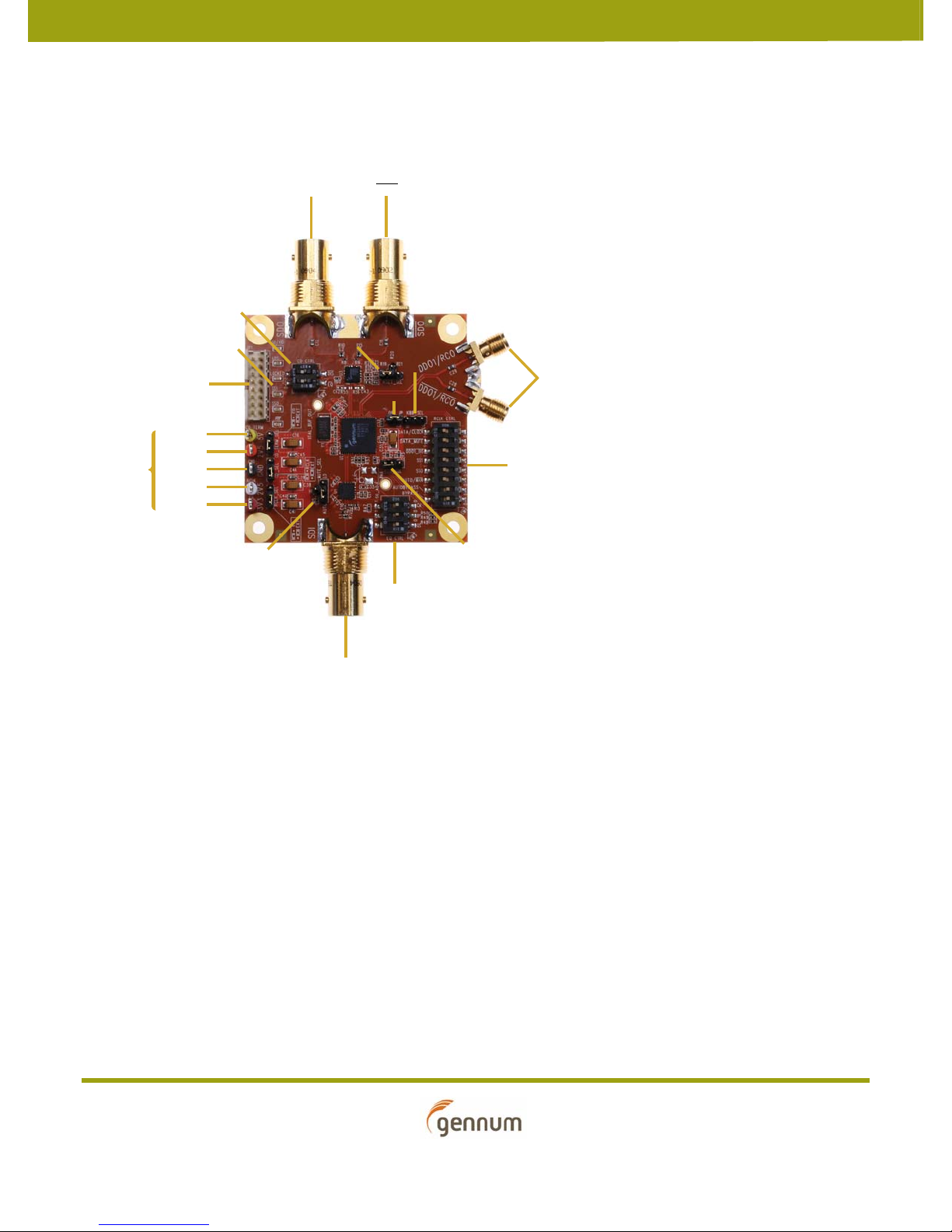
1. Evaluation Board User Guide
Figure 1-1 shows the inputs, outputs and power connections for the EB-GS2985-S.
SDO SDO
CD Control
(SW2)
RSET Resistor Select
CD_TERM_SEL
CD_SEL
RCLK_SEL
MUTE Select
(RSET_SEL)
SDI
KBB Input Select
(KBB_SEL)
ORL_JP
VCO Frequency Select
EQ Control
(SW3)
DATA1/RCLK Output
RCLK Control
(SW1)
(VCO_SEL)
Power
Supply
Connections
LEDs
SPI Interface
CD_TERM
CD
GND
RCLK
EQ
Figure 1-1: GS2985 Single-channel Evaluation Board (EB-GS2985-S)
EB-GS2985-S
Evaluation Board User Guide
52246 - 2 July 2009
5 of 25

1.1 SDI Inputs and Outputs
EB-GS2985-S features a single ended 75Ω input through a BNC connector (SDI) and two
single ended 75Ω outputs through two BNC connectors (SDO, SDO
).
1.2 DDO1/RCO Output
The EB-GS2985-S features two SMA connectors (DDO1/RCO, DDO1/RCO) for the
recovered clock RCO and RCO
the position on SW1 marked DATA/CLOCK
or the data DDO1 and DDO1. This can be selected using
.
1.3 SPI Interface
The EB-GS2985-S features an SPI interface (JP1) which is used to access all of the GS2985
registers. The SPI interface is automatically enabled when the Gennum USB dongle is
connected. The Gennum USB Dongle can connect the EB-GS2985-S to a computer via
USB. When the ribbon cable on JP1 is removed, the SPI interface is automatically
disabled and the board goes into legacy mode. The GS2985 registers will maintain their
settings until the board is powered-down, or reset via the SPI interface. Table 1-1
describes the two modes of operation.
Table 1-1: SPI Interface Modes of Operation
Mode Setting
Legacy Mode HIF = 1
SPI Mode HIF
= 0
1.4 GS2985 RCLK Control I/O
There are a variety of components on the EB-GS2985-S board to facilitate manual
control of the GS2985 device. These are described in the tables below.
Table 1-2: SW1 Positions
Switch Position Label Description HIGH (1) LOW (0) Default
1 BYPASS Bypass Bypass On Bypass Off 0
2 AUTOBYPASS Autobypass Autobypass On Autobypass Off 1
3AUTO/MAN
4 SS0 Data rate select [0] SS[1:0]
5 SS1 Data rate select [1] 0
Auto/Manual Automatically locks
to incoming data
rate
0 - Reserved
1 - 270 (Mb/s)
2 - 1485 or 1485/1.001 (Mb/s)
3 - 2970 or 2970/1.001 (Mb/s)
Manual data rate
select
1
0
EB-GS2985-S
Evaluation Board User Guide
52246 - 2 July 2009
6 of 25

Table 1-2: SW1 Positions
Switch Position Label Description HIGH (1) LOW (0) Default
6 DDO1_DIS DDO1 Disable DDO1 Mute Off DDO1 Mute On 1
7DATA_MUTE
8DATA/CLOCK
Table 1-3: VCO Frequency Select (VCO_SEL)
Position Connection Description
3V3 (default) Sets correct VCO voltage for
2V5 Sets correct VCO voltage for
Table 1-4: KBB Input Select (KBB_SEL)
Position Connection Description
HI KBB = VCC
Data Mute Data Mute Off Data Mute On 1
Data/Clock select DDO1/DDO1
selected
a 3.3V power supply
a 2.5V power supply
RCO/RCO selected 1
LOW KBB = GND
Not connected (default) KBB = unconnected
1.5 GS2984 EQ Control I/O
A switch (SW3) and a jumper (MUTE_SEL) facilitate the manual configuration of the
GS2984 Equalizer on the EB-GS2985-S evaluation board. These are described in the
tables below.
EB-GS2985-S
Evaluation Board User Guide
52246 - 2 July 2009
7 of 25
Table 1-5: SW3 Positions
Switch Position Label Description HIGH (1) LOW (0) Default
1 GS Gain Select Compensation for
2 BP Bypass Bypass On Bypass Off 0
3 CM Common Mode Set
Table 1-6: MUTE Select (MUTE_SEL)
Label Connection Description
AUTO (default) Auto Mute
HI Mute On
LO Mute Off
NOTE: CM should be
set to 1 when using
a 2.5V supply for the
Reclocker.
6dB flat attenuation
Output CM set to
2.1V
No change in gain 0
Output CM set to
2.9V
0
1.6 GS2988 CD Control I/O
A switch (SW2) and a jumper (RSET_SEL) facilitate the manual configuration of the
GS2988 Cable Driver on the EB-GS2985-S evaluation board. These are described in the
tables below.
Table 1-7: SW2 Positions
Switch Position Label Description HIGH (1) LOW (0) Default
1EQInput trace
2DIS
EB-GS2985-S
Evaluation Board User Guide
52246 - 2 July 2009
equalization
Output disable Output 1 enabled Output 1 disabled 1
Input trace
equalization Off
Input trace
equalization On
1
8 of 25
 Loading...