

Page 1

USER MANUAL
Genmitsu
CNC Router 3018-PRO
V1.1 Sept 2020
Page 2

Contents
Welcome
Disclaimer
Part 1 - Unboxing
Part 2 - Assembly
..........................................................................................................................................
.......................................................................................................................................
...........................................................................................................................
...........................................................................................................................
Part 3 - Software & Drivers
Part 4 - Getting Started
.................................................................................................................
Part 5 - Offline Controller
..........................................................................................................
.............................................................................................................
02
03
04
08
25
31
32
01
Page 3
Welcome
Thank you for purchasing the Genmitsu 3018-PRO CNC Router from SainSmart.
Included in your package will be a Micro SD card. On the Micro SD Card, you will find:
● Assembly instruction videos
● PDF version of this manual
● Windows USB Driver
● GrblControl/Candle software for Windows
● Sample files
● Offline Controller control files
These files can also be downloaded from
SainSmart Online Resource Center
https://docs.sainsmart.com/3018pro
Before attempting to assembly the 3018 PRO, please watch the assembly video on the
Micro SD card that came with your machine. This will save time and avoid mistakes.
02
For technical support, please email us at [email protected].
Help and support is also available from our Facebook group.
(SainSmart Genmitsu CNC Users Group)
Scan QR code
to join the group
Page 4
Disclaimer
Before operating your Desktop CNC Machine, please read the manual. Failure to do so may lead to personal injury, poor results,
or damage to the CNC Machine. Anyone who operates the Desktop CNC machine should know and understand the contents of
this manual.
SainSmart cannot control the conditions in which you assemble your Genmitsu CNC machine or verify if it was done properly.
We do not assume responsibility and expressly disclaim liability for loss, injuries, damage, or expense arising out of, or in any way
connected with the assembly, handling, storage, use, or disposal of the product.
The information in this manual is provided without any warranty, expressed or implied, regarding its correctness.
Please be careful when using your CNC machine. This machine is an electrical device with moving parts and
dangerous areas.
● Genmitsu CNC Machines are for Indoor Use Only.
● You must be 18 years or older to operate this machine, unless supervised by a knowledgeable adult familiar with the machine.
● Wear the proper Personal Protection Equipment (Safety Glasses etc.).
● Always place the CNC Machine on a stable surface.
● The SainSmart Genmitsu CNC Machine is supplied with Switchable Power Supply 230 VAC or 110VAC. Never use a different
power supply; it may cause malfunctions or damage to the machine.
● Ensure the Emergency stop button is easily accessible at all times.
● Never disassemble the Power Supply or Electrical Components. This will VOID the warranty.
● DO NOT TOUCH the machine spindle, or place any body part near the working area when the machine is operating. Serious
Injury may occur.
● DO NOT leave children unsupervised with the CNC Machine even when it’s not operating. Injury may occur.
● DO NOT leave the machine unattended while it's operating.
● Ensure your CNC Machine is in a well-ventilated area. Some Materials may discharge smoke or fumes during operation.
03
Page 5
Part 1 - Unboxing
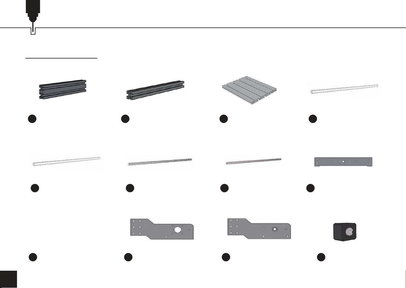
Please make sure all the following parts are included. If you are missing any part or have any questions, please email us at
04
(2) Aluminum Profile
1
20 x 40 x 290 mm
(2) Guide Rail
5
Y Axis, Ø10 x 290mm
Bakelite Resin Plate B Bakelite Resin Plate C Bakelite Resin Plate D (2) Stepper motor
9
(2) Aluminum Profile
2
20 x 20 x 360mm
Lead Screw 365mm
6 7 8
10 11
Aluminum Profile
3 4
300 x 180mm
Lead Screw 295mm Bakelite Resin Plate A
(2) Guide Rail
X Axis, Ø10 x 360mm
12
Page 6
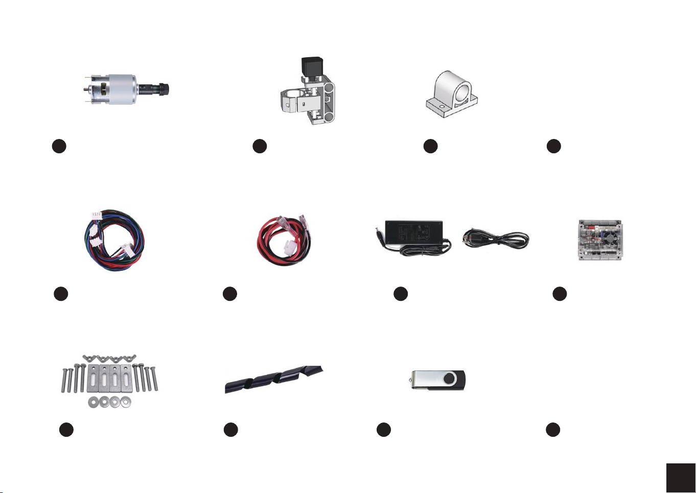
Spindle with ER11 installed
13
X-Z Axis Assembly
14 15 16
(4) Slider (10) Milling Cutter
(3) 4-Pin Motor Harness
23
(4) Plate Clamp Spiral Wire Wrap USB Disk with SD Card
27
Spindle Motor Harness
24 25 26
24V Power Supply
28 29
Control Board &
Fan & Case
(4) Allen Wrench
30
2.0mm,2.5mm,
3.0mm,4.0mm
05
Page 7
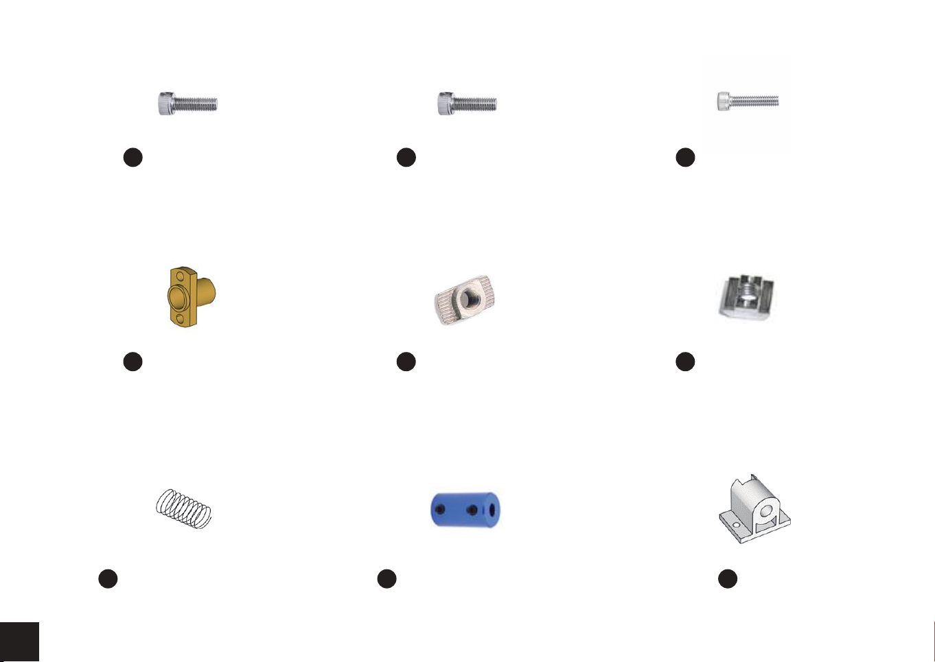
(4) Bolt M5 x 10
31
(34) Bolt M5 x 16
32
(8) Bolt M3 x 14
33
06
(2) Copper Nut
34
(2) Anti-Backlash Spring
37
(16) T-Nut 20M5
35
(3) Coupling & Set Screw
38
(10) T-Nut 30M5
36
Nut Seat
39
Page 8
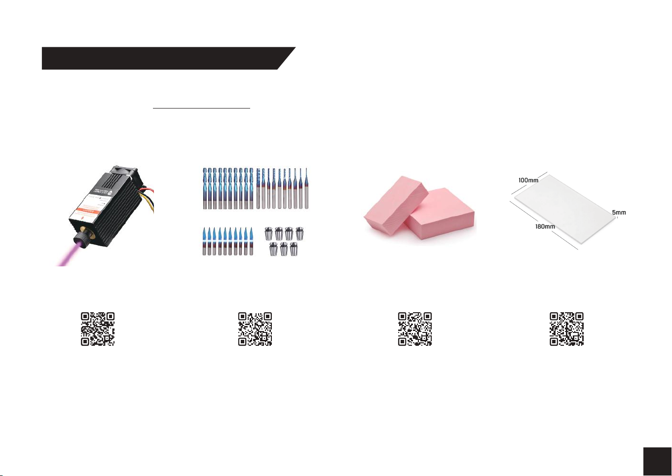
Optional Accessories (Not Included)
Consider following optional upgrades or accessories to make your CNC experience better!
You can find them on www.sainsmart.com.
Save 10% with discount code 3018PRO10
5.5W Laser Module
CNC Router Bits Essential Kit
Scan QR codes to learn more
Resin Board for CNC
Engraving, 2-Pack
Acrylic Sheet for CNC,
180 x 100 x 5mm, 4-Pcs
07
Page 9
Part 2 - Assembly
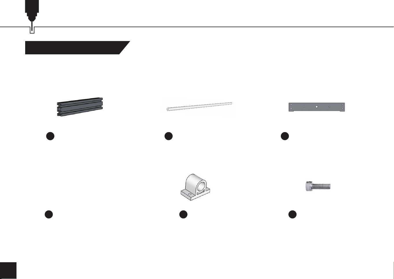
Step 1 Base Installation
What you will need
08
(2) Aluminum Profile
1
20 x 40 x 290 mm
Bakelite Resin Plate B
9
(2) Guide Rail
5 8
Y Axis, Ø10 x 290mm
(4) Slider (12) Bolt M5 x 16
15
Bakelite Resin Plate A
32
Page 10
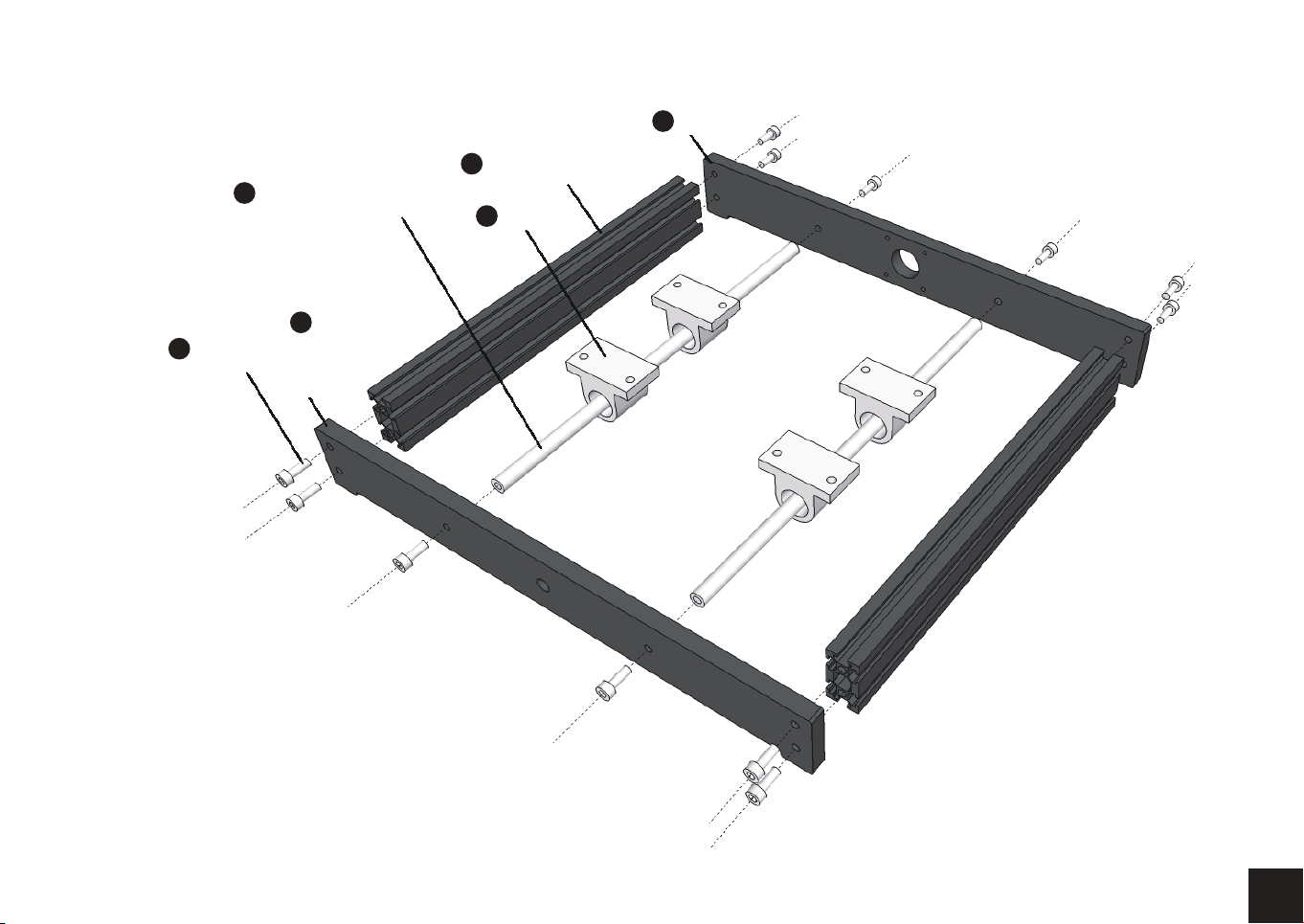
(2) Guide Rail
5
Y Axis, Ø10 x 290mm
(2) Aluminum Profile
1
20 x 40 x 290 mm
(4) Slider
15
Bakelite Resin Plate B
9
8
Bakelite
Resin
Plate A
32
(12) Bolt
M5 x 16
Notes: Make sure this assembly is square
and that the sliders are installed on the
guide rails with the holes to the front and
rear of the base.
09
Page 11
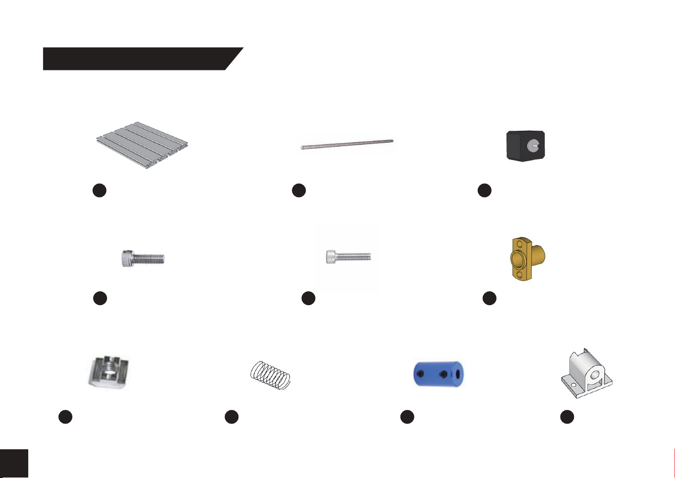
Step 2 Worktable Assembly
What you will need
10
32
(10) T-Nut 30M5
36
Aluminum Profile
300 x 180mm
(10) Bolt M5 x 16
Anti-Backlash
37
Spring
Lead Screw 295mm Stepper motor
73
(4) Bolt M3 x 14
33
Coupling
38
& Set Screw
12
34
Copper Nut
39
Nut Seat
Page 12
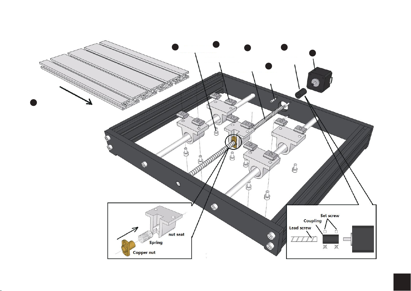
Aluminum
Profile
3
300 x 180mm
32
(10) Bolt
M5 x 16
36
(10) T-Nut
30M5
7
Lead
Screw
295mm
33
(4) Bolt
M3 x 14
38
Coupling
& Set Screw
12
Stepper motor
11
Page 13
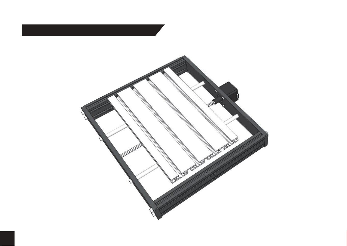
Step 3 Base Assembly - Completed View
Top view
12
Page 14
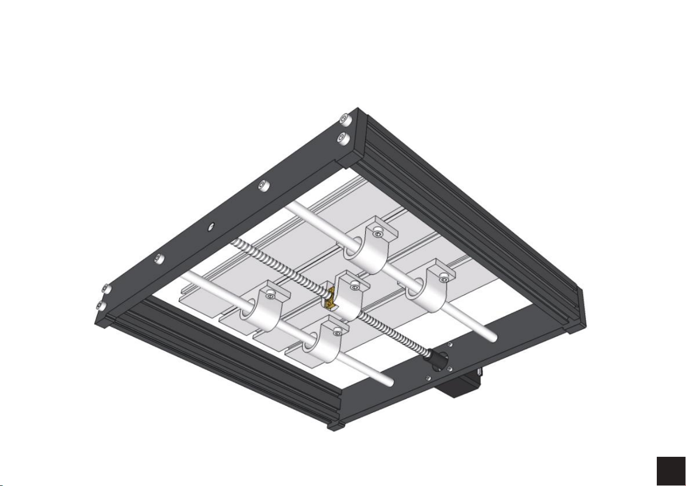
Top view
13
Page 15
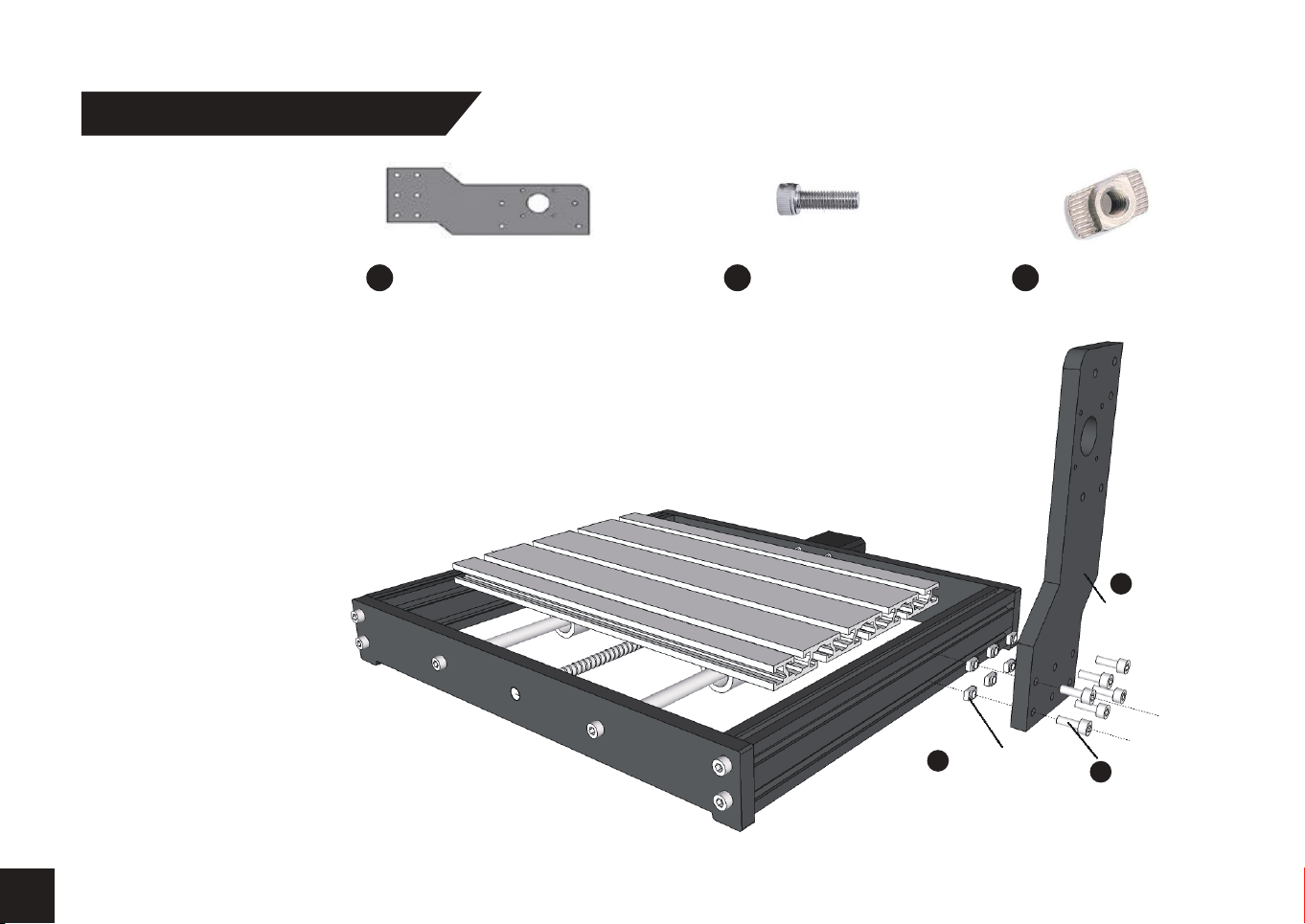
Step 4 Top Frame Assembly
What you will need
Bakelite Resin Plate C (6) Bolt M5 x 16
10
32
STEP 1: Position the Bakelite Pillars with a spacing of 46.5mm between rear frame
piece and back of the pillar as shown in the Completed View on the next page.
Tip: When installing T-Nuts it helps to twist them onto the bolts a few turns keeping
them in place before placing into the Aluminum slot.
(6) T-Nut 20M5
35
(6) T-Nut 20M5
35
32
10
Bakelite Resin
Plate C
(6) Bolt
M5 x 16
14
Page 16
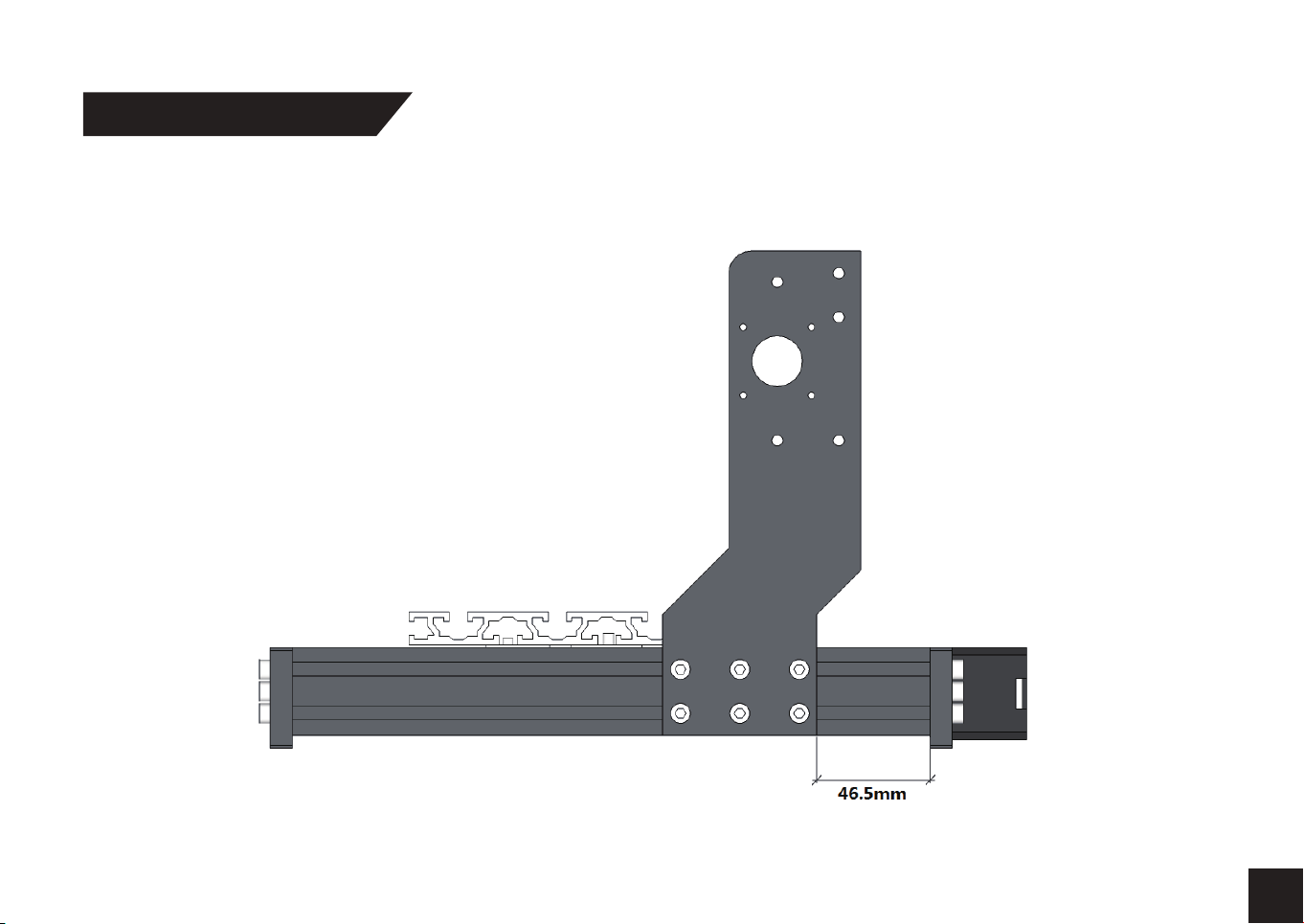
Step 5 Completed View
Note: Back edge of Bakelite-C must be 90 degrees to the base.
15
Page 17
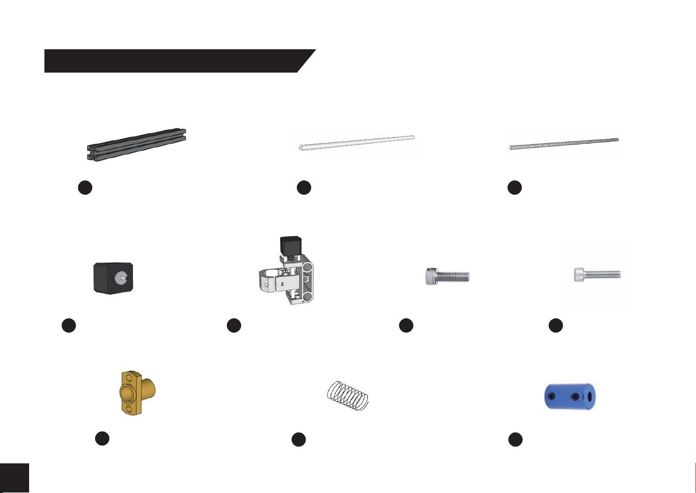
Step 6 X-Z Axis Assembly Installation
What you will need
(2) Aluminum Profile
2
20 x 20 x 360mm
(2) Stepper motor
12
Copper Nut
34
X-Z Axis Assembly
14
(2) Guide Rail
X Axis, Ø10 x 360mm
Anti-Backlash Spring
37
(4) Bolt M5 x 16
32
Lead Screw 365mm
64
(4) Bolt M3 x 14
33
Coupling & Set Screw
38
16
Page 18
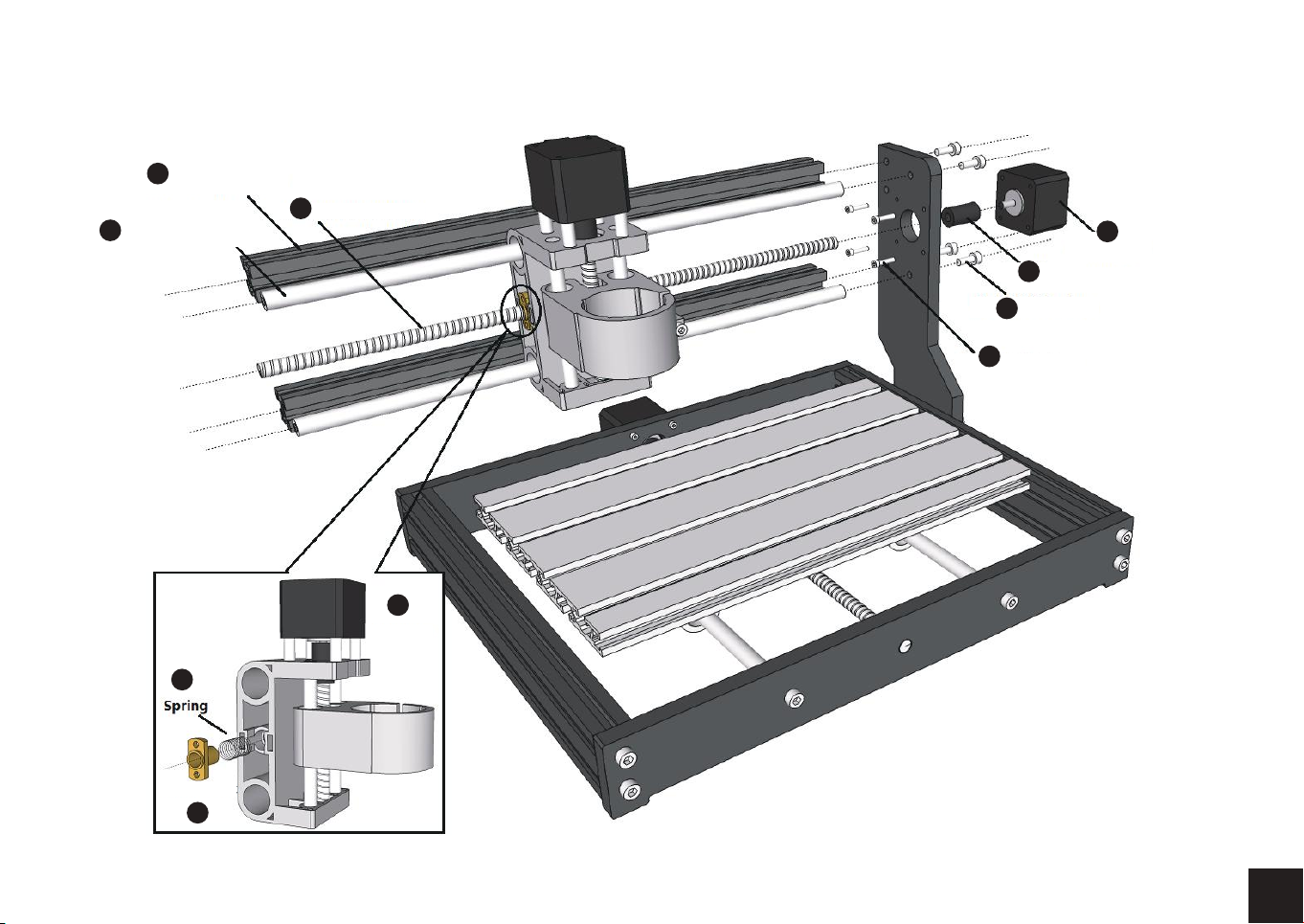
2
(2) Guide
Rail X Axis
4
Ø10 x 360mm
(2) Aluminum Profile
20 x 20 x 360mm
6
37
Lead Screw 365mm
14
X-Z Axis
Assembly
Coupling &
38
Set Screw
(4) Bolt M5 x 16
32
(4) Bolt M3 x 14
33
12
Stepper
motor
Brass Nut
34
17
Page 19
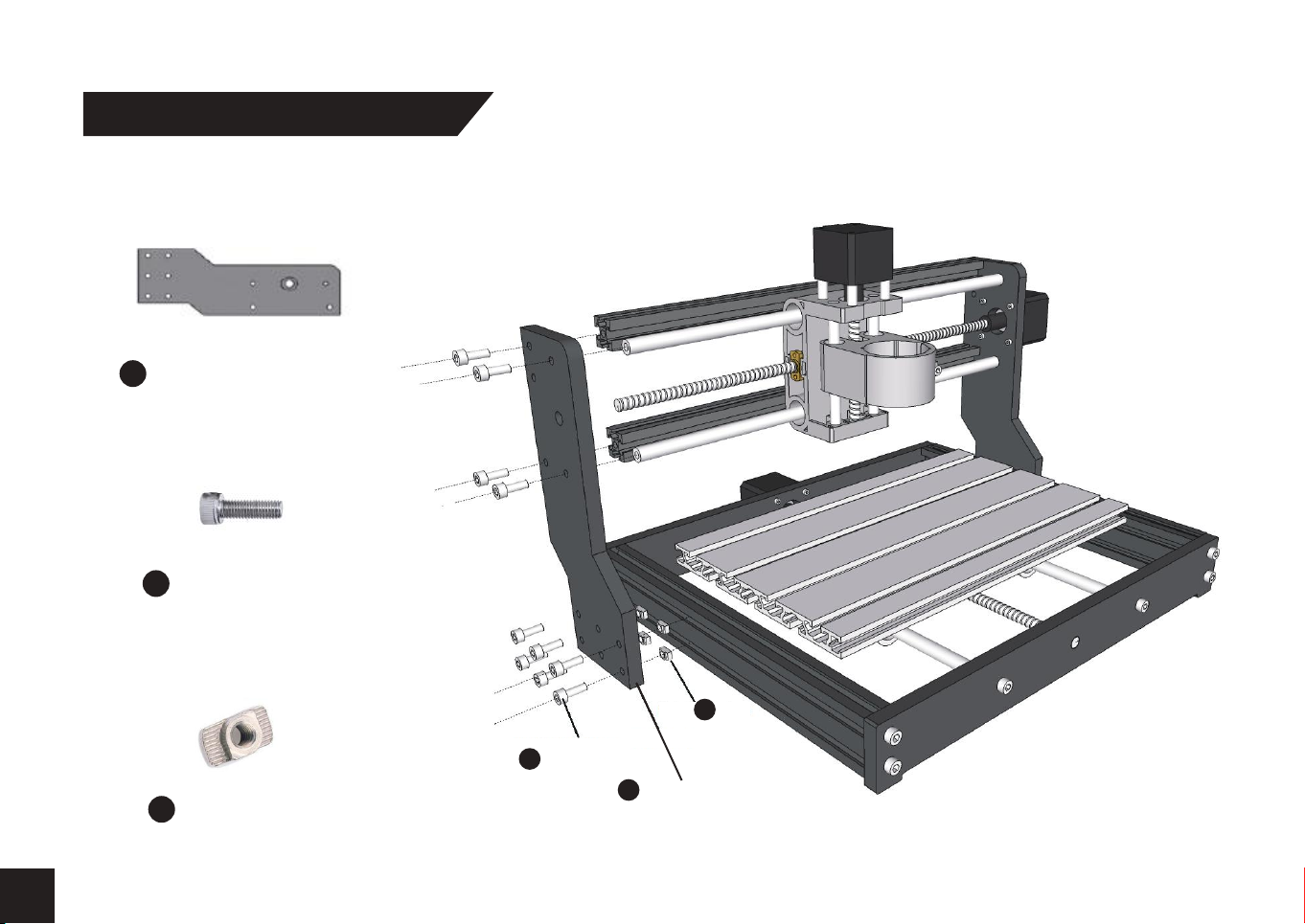
Step 7 Bakelite-D Installation
What you will need
Bakelite Resin Plate D
11
(10) Bolt M5 x 16
32
18
(6) T-Nut 20M5
35
32
(10) Bolt
M5 x 16
35
(6) T-Nut
20M5
11
Bakelite Resin Plate D
Page 20
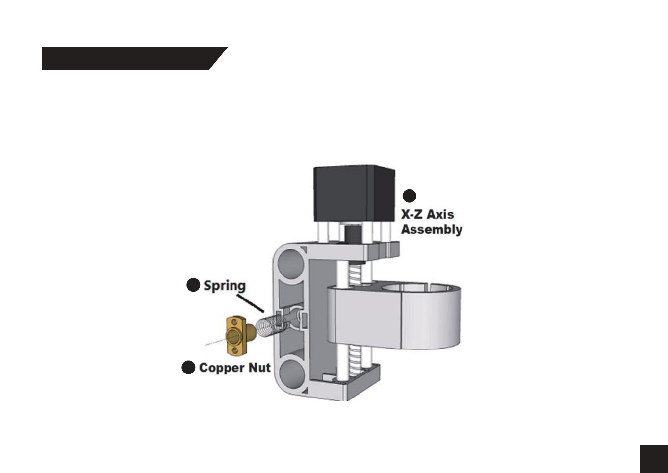
Step 8 Z - Axis Assembly
Step 1: Prepare the Z Axis Carriage and Leadscrew.
Compress the Anti-Backlash Spring into the Hole shown below.
Use the Copper Nut to slide into the spring and hold it into place.
While compressed, thread the Leadscrew through the assembly.
37
14
34
19
Page 21
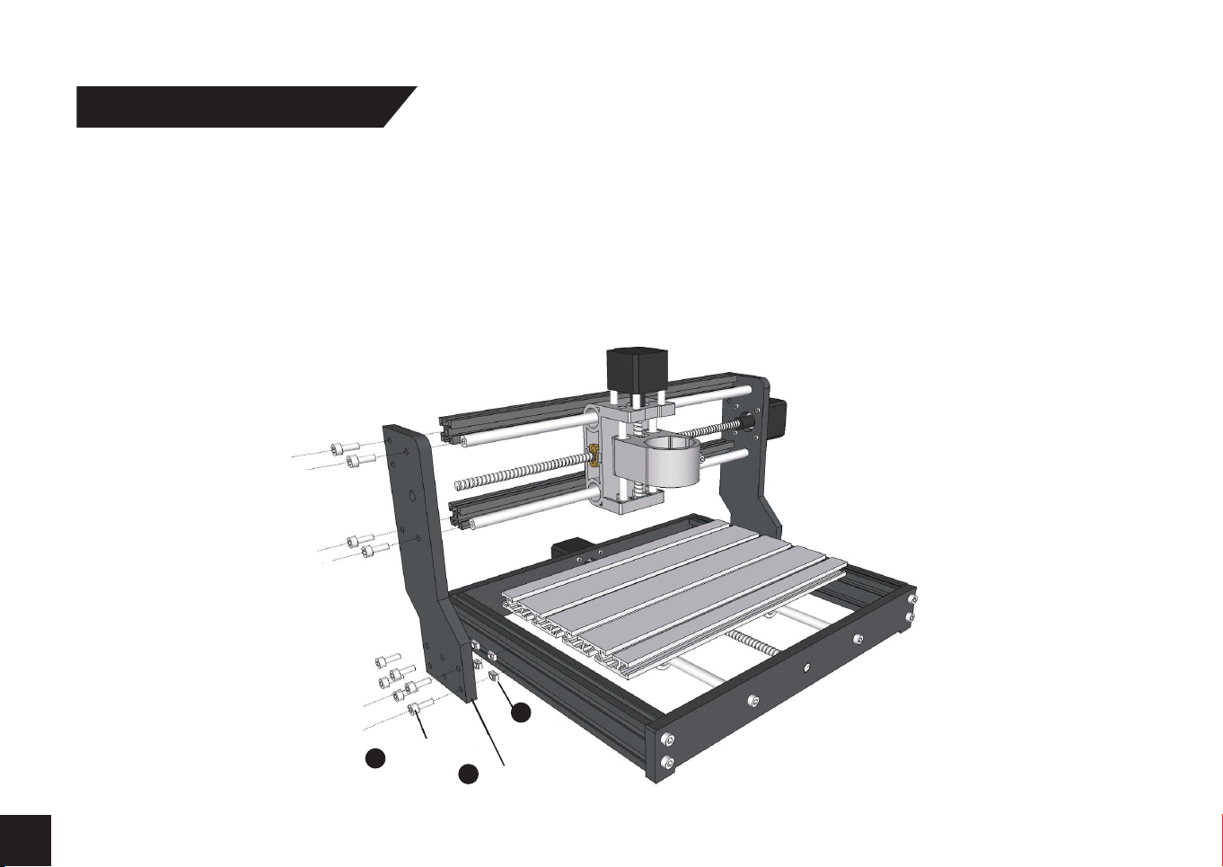
Step 9 X-Axis Assembly
Step 1: Install (2) Aluminum Frame pieces to Bakelite Pillar C with M5x16mm Bolts.
Step 2: Install (2) Linear Rods into the holes next to the Frame pieces using M5x16mm Bolts.
Step 3: Prepare the Stepper Motor and Install the Coupler and screw. Set the screw positioned
on the Flat side of the Stepper Motor Shaft.
Step 4: Slide the Z-Axis Assembly onto the Linear Rods. Push the Assembly to the right until the
Leadscrew is positioned inside the coupler. Secure the Leadscrew with the coupler set screw.
Step 5: Install Bakelite Pillar -D. Leave a 46.5mm space between the rear of the pillar and back frame piece.
20
32
(10) Bolt
M5 x 16
35
(6) T-Nut
20M5
11
Bakelite Resin Plate D
Page 22
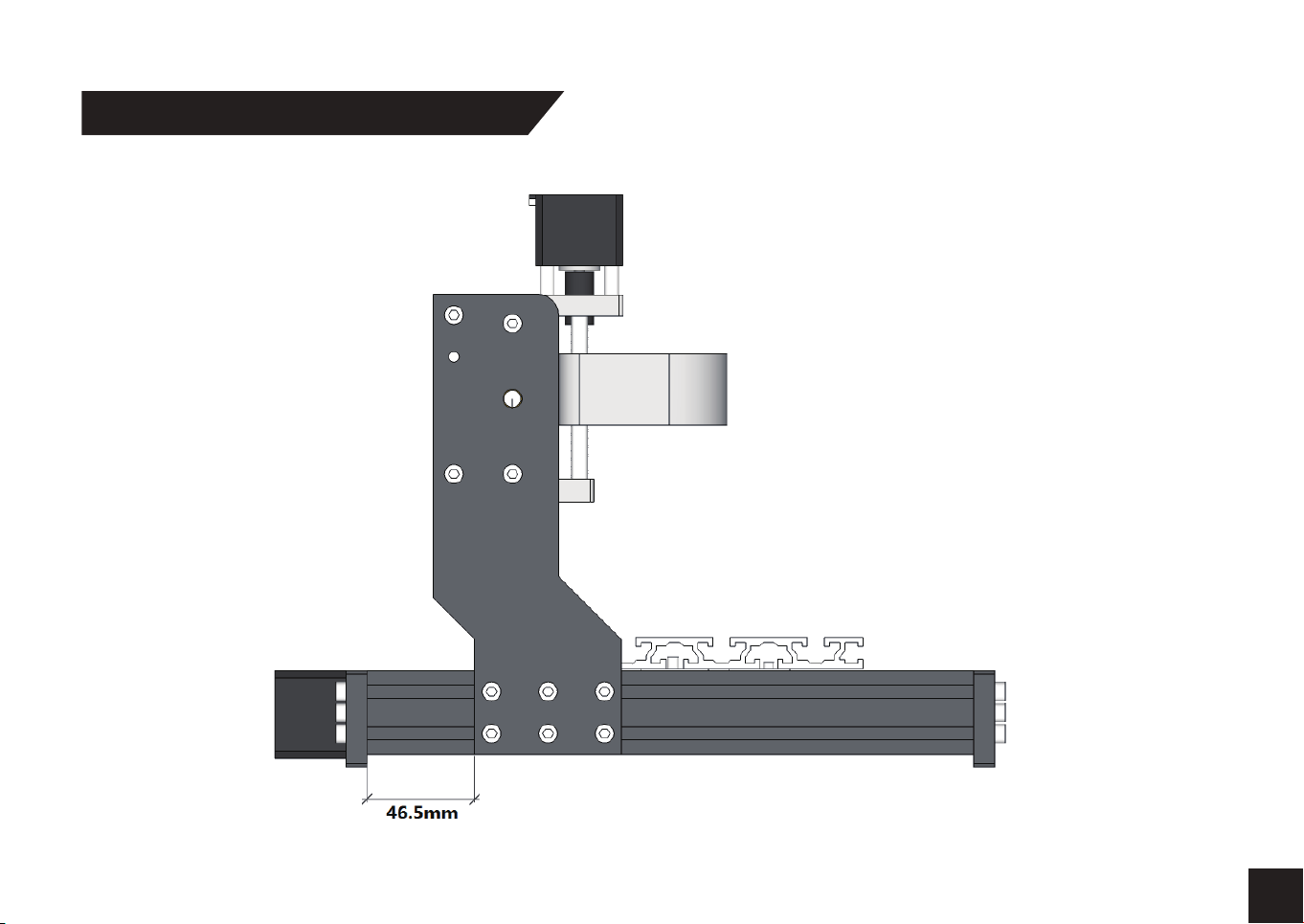
Step 10 X - Control Board Installation
21
Page 23
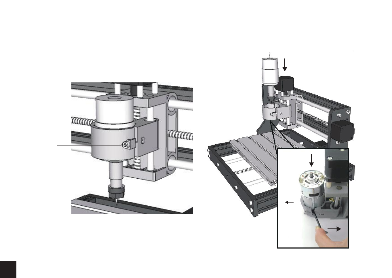
Do not overtighten the bolt. This can damage the holder. Slide the Spindle down until about half an inch of sleeve is showing.
Caution
22
Page 24
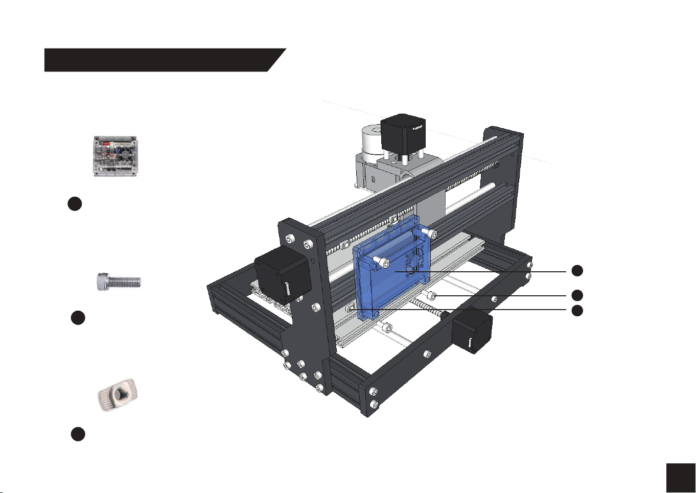
Step 11 Control Board Installation
What you will need
Control Board &
26
Fan & Case
(4) Bolt M5 x 10
31
Control Board &
26
Fan & Case
(4) Bolt M5 x 10
31
(4) T-Nut 20M5
35
(4) T-Nut 20M5
35
23
Page 25
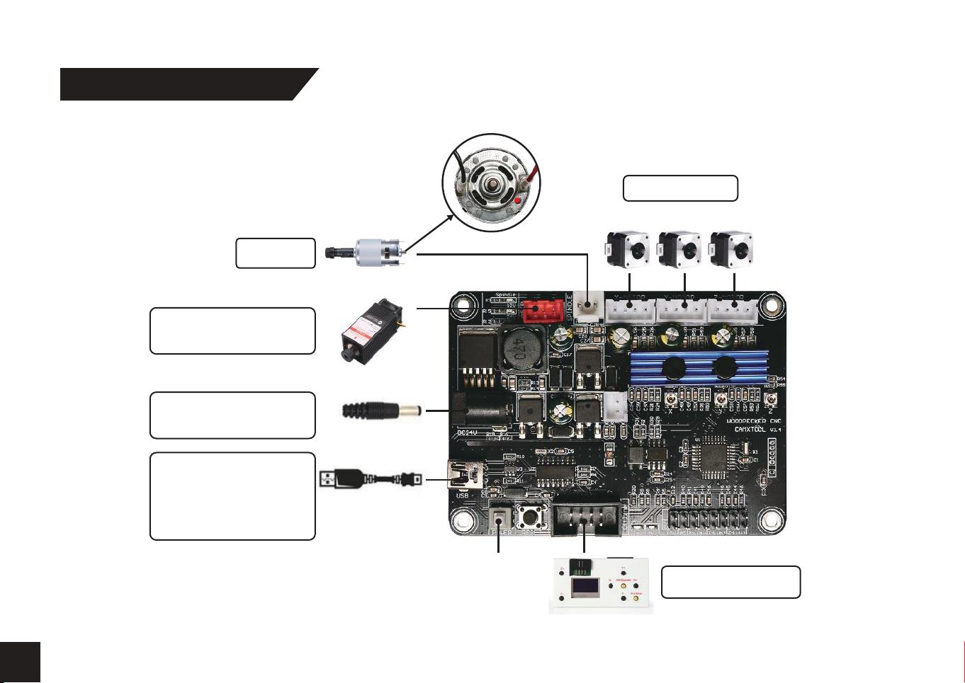
Step 12 Wiring Diagram
Connect the red wire to the
port next to the red mark
Spindle
Laser (12V 5Amax)
(Not include)
24V DC Power
adapter
USB
Connect your CNC to
computer using the
bundled USB cable
17
POWER
ON/OFF
Stepmotor
X Y Z
Offline controller
24
Page 26
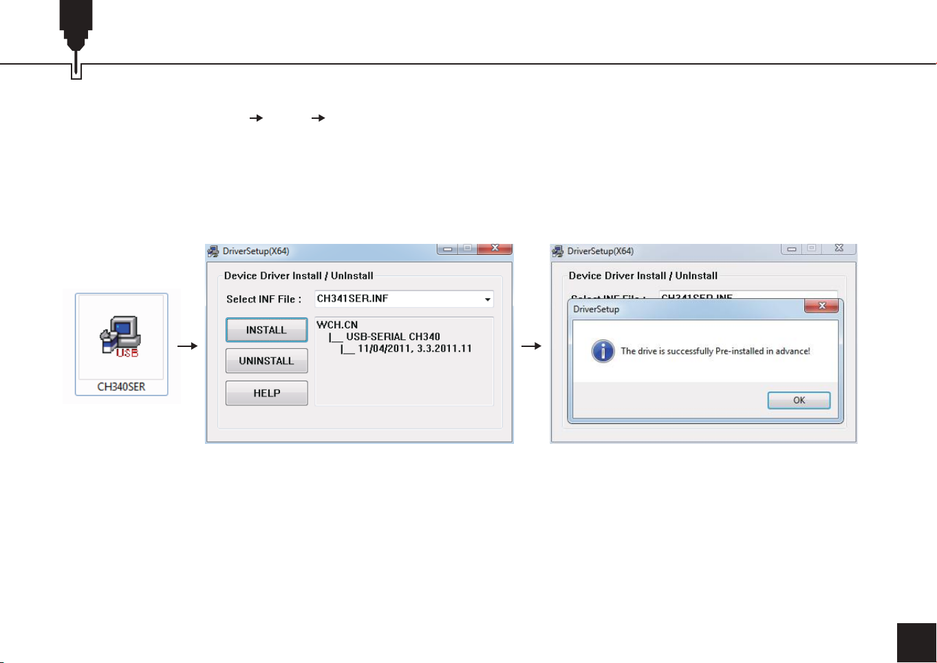
Part 3 - Software & Drivers
1. Install the driver ( software Driver CH340SER.exe )
25
Page 27
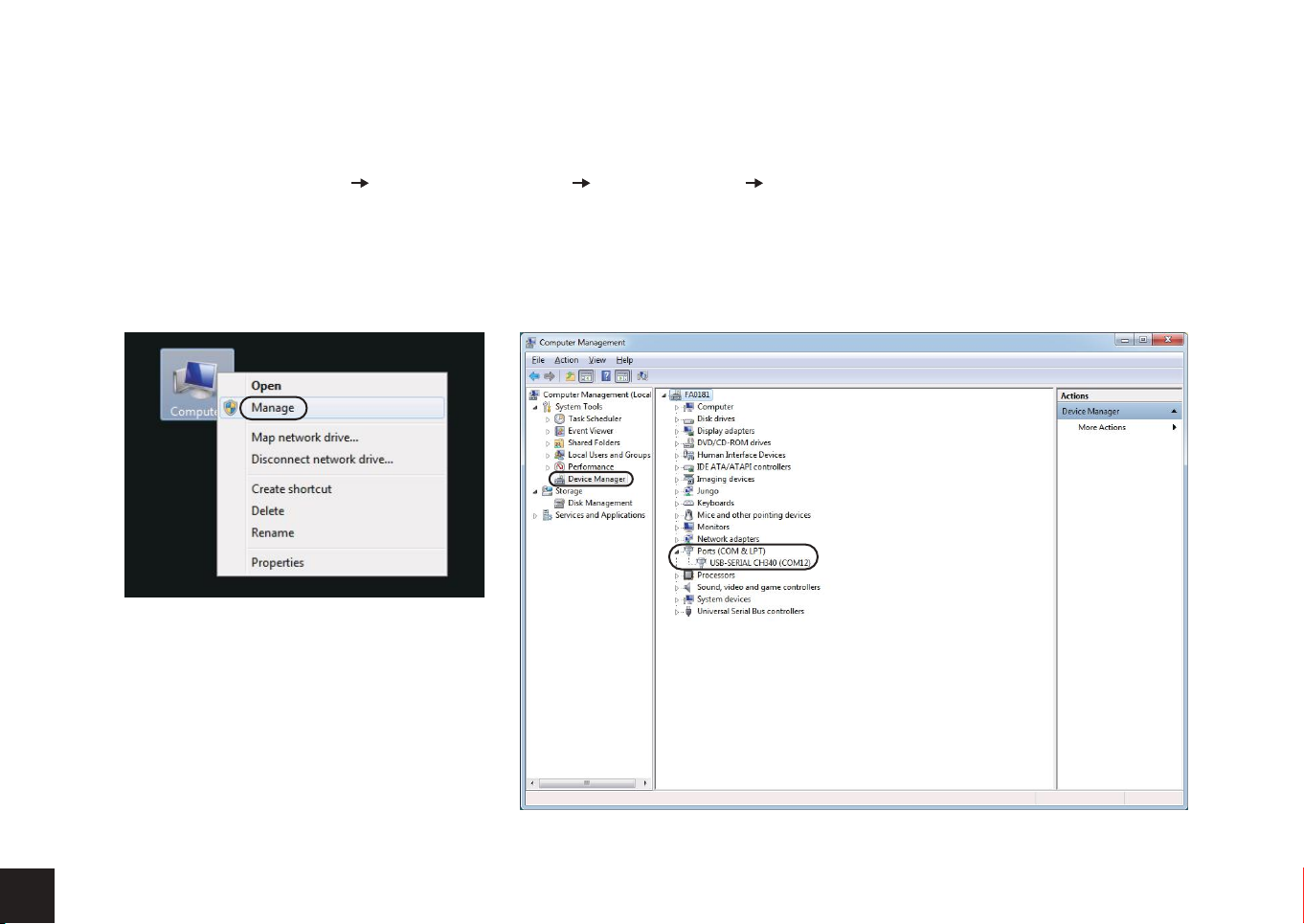
2. To Determine your Machine's COM port:
• Windows XP: Right click on "My Computer", select "Manage", select "Device Manager".
• Windows 7: Click "Start" Right click "Computer" Select "Manage" Select "Device Manager" from left pane.
• In the tree, expand "Ports (COM & LPT)"
• Your machine will be the USB Serial Port (COMX), where the “X” represents the COM number, for example COM12.
• If there are multiple USB serial ports, right click each one and check the manufacturer, the machine will be "CH340".
1
2
3
26
Page 28
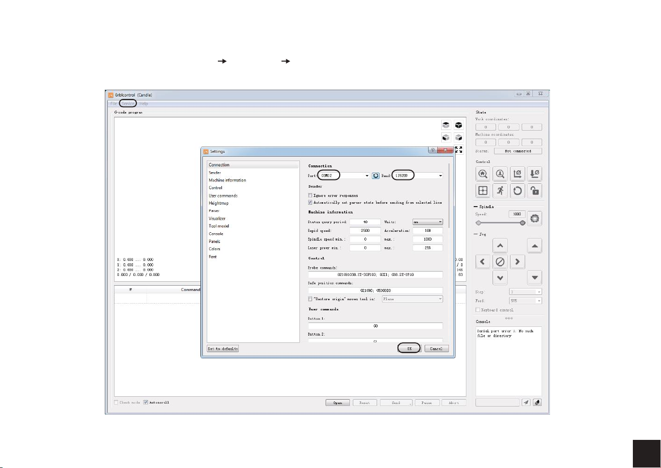
3. Open Grblcontrol software(software Grblcontrol GrblControl.exe)
choose the correct port
27
Page 29
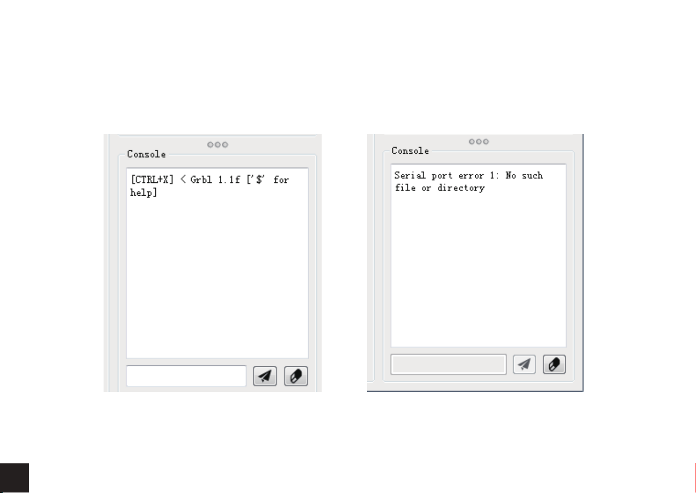
• Console window print ” [CTRL+X] < Grbl 1.1f ['$' for help]” If the connection is successful.
• Console window print ” Serial port error 1: No such file or directory “ indicate that the connection is failed.
successful unsuccessful
28
Page 30
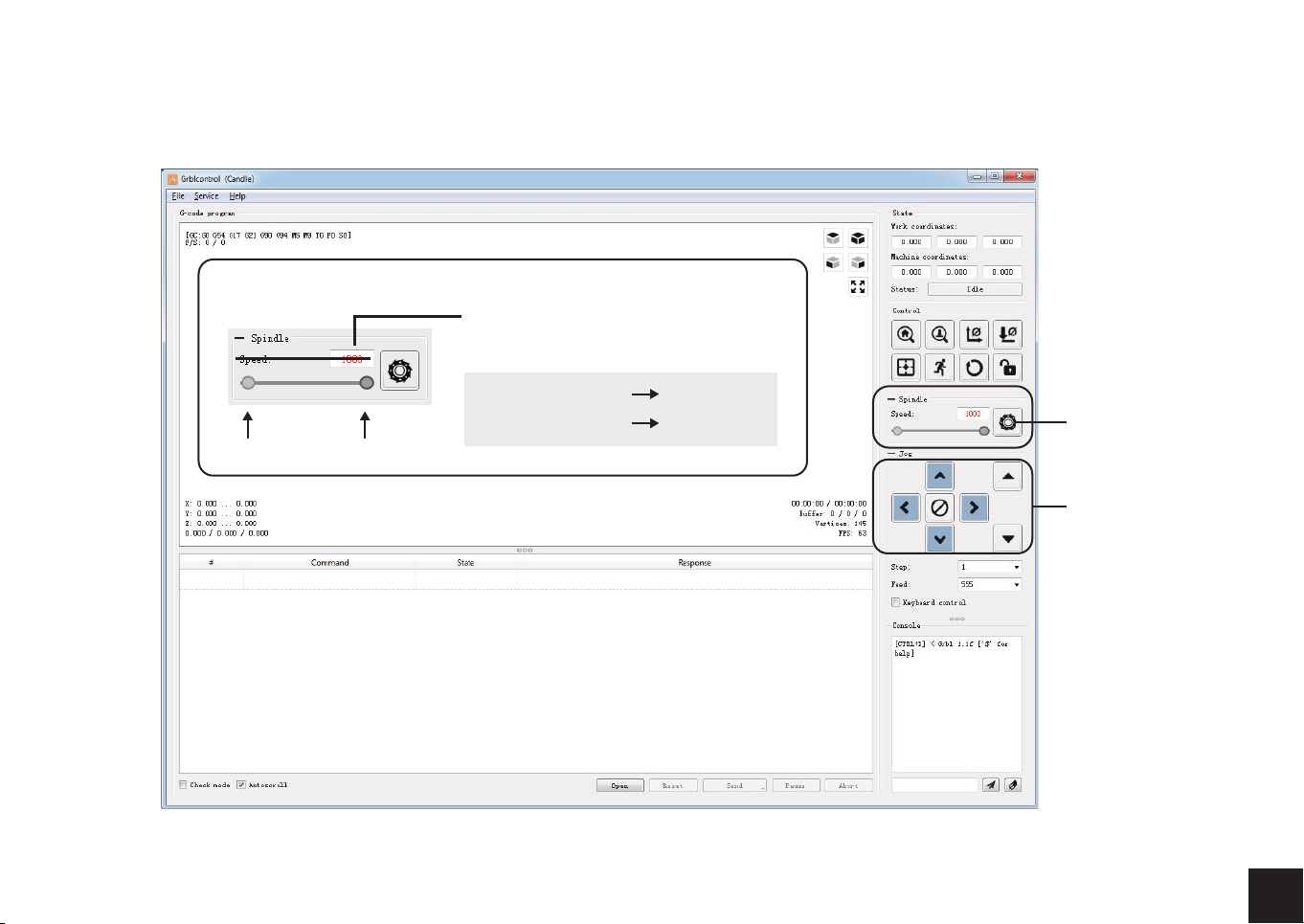
• Grblcontrol Use
The spindle speed:
0% 100%
It does not represent the actual
speed, and it represents the ratio.
And this percentage is not linear.
100 = 100/1000 10%
1000 = 1000/1000 100% max
spindle
on/off
The X Y Z
axis jog
29
Page 31
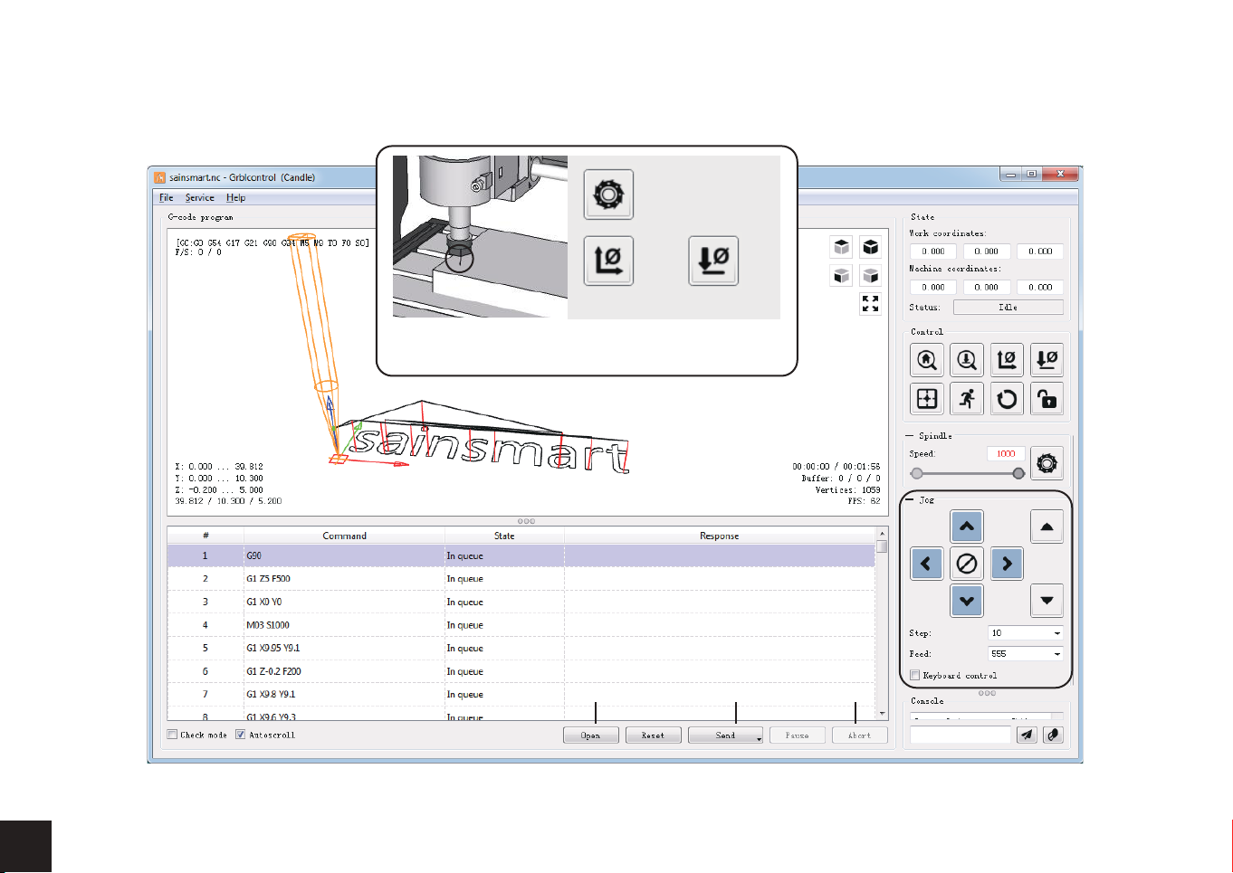
• Tool setting
spindle should
be on when
moving the bits
zero XY zero Z
Use the jog to move the milling cutter.
Then click button zeroXY and zeroZ.
20
30
Open the G-code file Start working End
Page 32

Part 4 - Getting Started
Basic Machine Tests Now that you have your CNC machine all assembled and wired, it is time to make sure that it operates correctly.
This is the recommended start up order for the system.
1. Make sure that the USB cable from the CNC machine is plugged into your computer, then start the computer.
2. Start the Candle program and verify in the status window that no errors are showing. Normally, it will show “Idle” if it has connected
to the Controller Board properly. If an “Alarm” error is showing, with your mouse, click the Candle “Reset” then “Unlock” buttons in
that order to get to the “Idle” condition.
3. Make sure that the 24-volt power supply is connected to the Controller Board and then to the power mains. - Turn on the Controller
Board by pressing the white “On/Off” button.
4. Next, click on the “Spindle “button to turn on the spindle motor. Move the slider left and right to verify that the motor speed changes.
5. Set the “Feed:” to a value in the 200 to 500 range. With the mouse, click on the left set of direction buttons to verify that the X and Y
axes are moving. In a like manner, click on the rightmost up and down buttons to verify that the Z axis is moving. If all of these tests
complete without any issues, you can be assured that your CNC machine is working correctly. Shutting the machine down uses the
reverse of the startup process.
6. Turn off the Controller Board.
7. Unplug the 24-volt DC supply from the mains.
8. Shut down the Candle program. - Turn off the computer. Remember, if you run the CNC machine from the Offline Controller, the
USB cable must be disconnected from the Controller Board.
21
31
Page 33

Part 5 - Offline Controller
Notice: When using the offline controller, remove the USB cable from the PC. Offline controller and PC cannot be used
together.
1. Connect offline controller to PC via USB cable.
22
32
Page 34
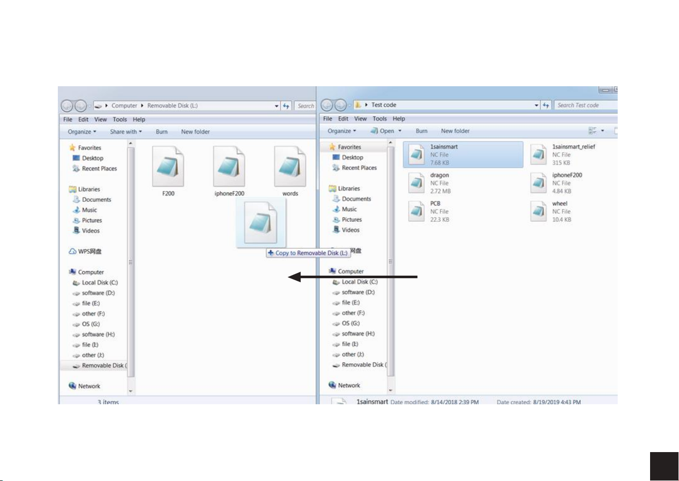
2. Then copy the NC file to the offline controller.
23
33
Page 35
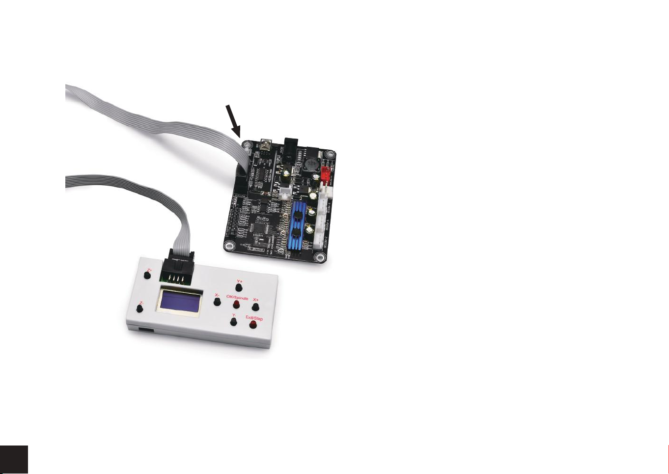
3. Offline controller connected to the control board.
22
34
4. Press the [X+/X-/Y+/Y-/Z+/Z-] key to move the spindle to the machine origin, select the engraving file, click the [OK] key to start
engraving.
Page 36
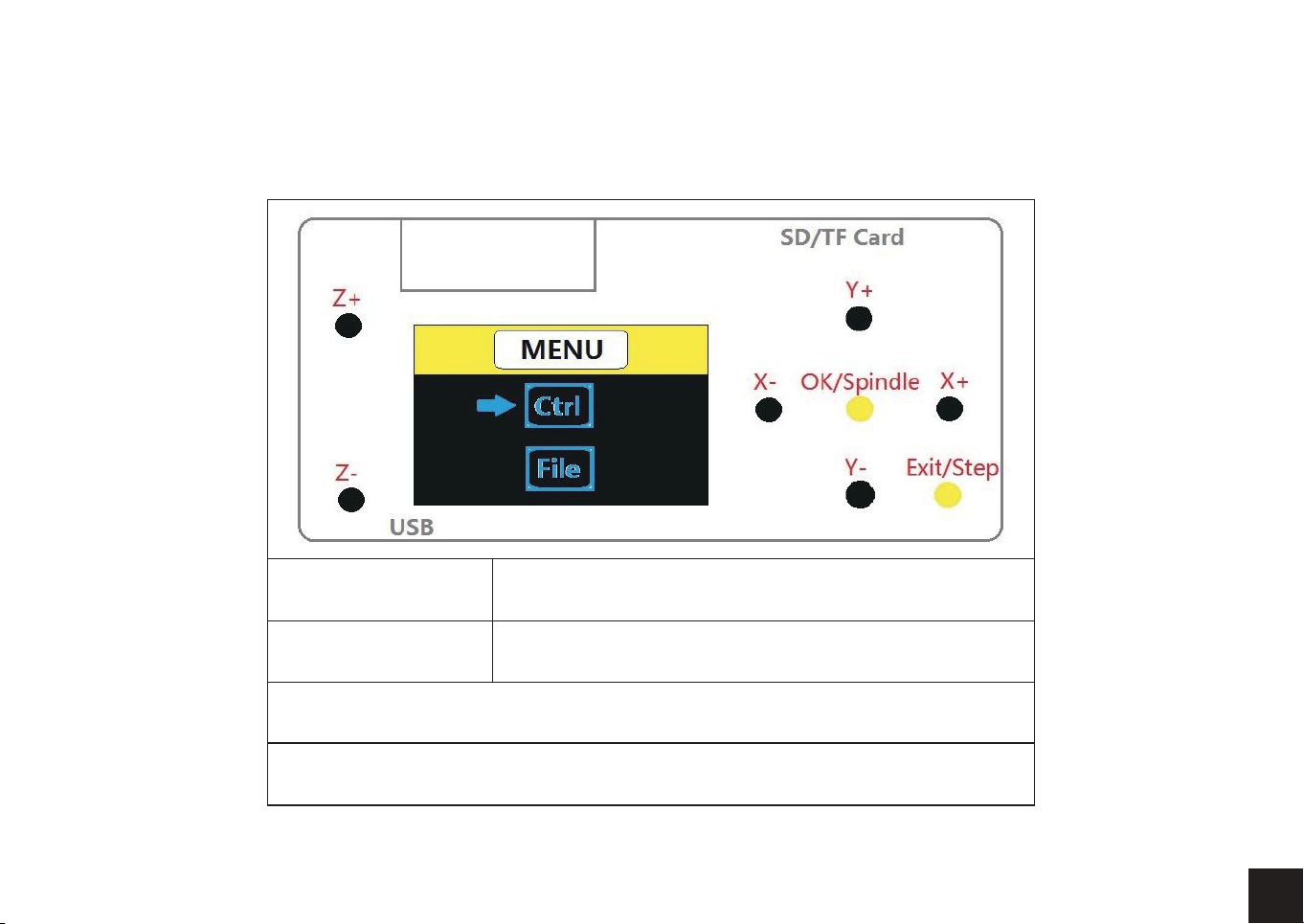
5. Interface introduction
A. Menu Page
Ctrl Machine Control
File Use the G-code file
Press key [Y+] or [Y-] to select
Press key [OK] to Enter
2135
Page 37
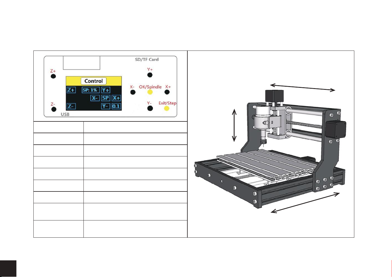
B. Ctrl Page
Reference direction
X-
X+
Z+
2236
X+
X-
Y+
Y-
Z+
Z-
OK/Spindle(SP)
Exit/Step
SP:1%
X-axis positive direction
X-axis negative direction
Y-axis positive direction
Y-axis negative direction
Z-axis positive direction
Z-axis negative direction
Spindle On/Off
Long press to exit, short press to
change step (0.1/1/5/10mm)
Power to spindle (Press [OK]+[Z+]=add,
Press [OK]+[Z+]=reduce)
Z-
Y-
Y+
Page 38
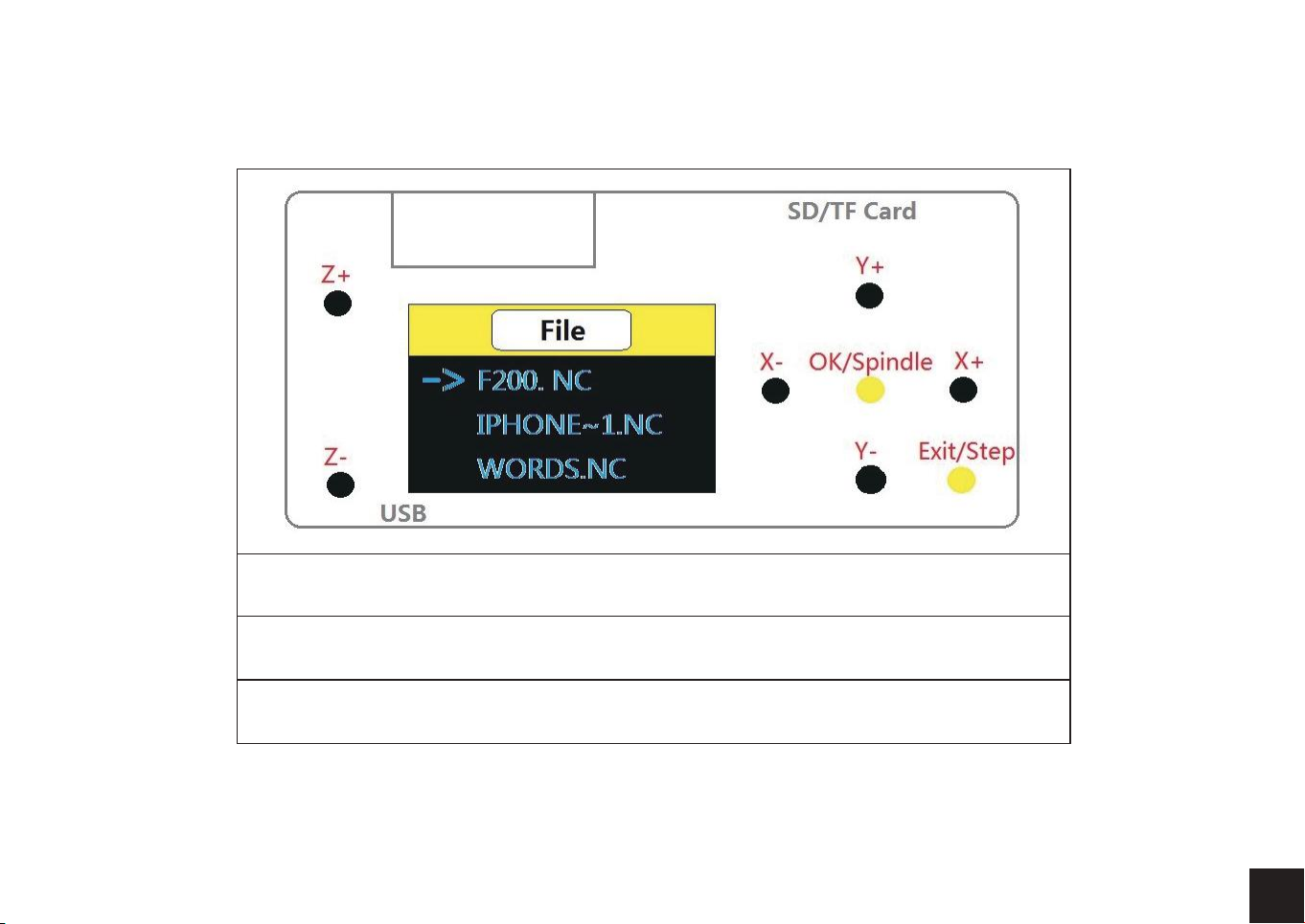
C. File Page
Press key [Y+] or [Y-] to select file
Press key [OK] to Enter
Press key [OK] to begin if you are ready.
2337
Page 39

Genmitsu
Desktop CNC & Laser
www.sainsmart.com
Vastmind LLC, 5892 Losee Rd Ste. 132, N. Las Vegas, NV 89081
 Loading...