

Page 1
Genius Gate Systems Ltd
4 Wayside Green Woodcote Reading Berks RG8 0QJ
Directors: D.M.Pearson. M.J.Thornton. J.A.Pearson Registration No: 4557960 (England)
V.A.T.No: 815 9757 88
Page 1
Setup Instructions of the DMG1 6/6 Telecommander
Genius Gate
Systems Ltd
DMG1 6/6
www.Genius-Systems.co,.uk
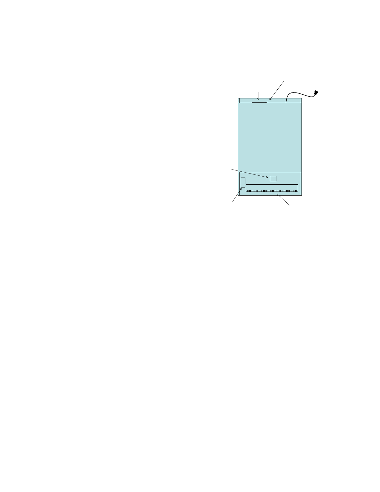
SIM
CARD
Aerial Lead
Connector Strip
DIP Switch
Power input
SIM Card
Status indicator
Before attempting to set up the unit you will need the following:
1. A suitable weather proof cabinet to install the complete system. The DMG is NOT suitable for
outside installation.
2. A SIM card for any of the GSM networks.
The SIM may be on any Tariff. But it is best to check the billing is per second not per minute
as few calls will extend to a minute in normal use.
3. A suitable Power supply of nominal Voltage 12 Volts DC (11 to 14 Volts) terminating in a
2.1mm female plug with the centre contact being Positive. It should be externally fused at 2
A although the mean current is about 350mA. The negative line must be grounded and/or
connected to the ‘Common’ line for all of the other equipment
4. A GSM Dual band Antenna with a Female FME connector. This can either be directly
connected to the flying antenna lead or via an extension lead and adaptors as needed.
Note: We can advise on or supply any of the above items if desired.
Set Up – Basic with default settings
The default setting will give no call forward and call duration when answered of around 30
seconds. The call duration timer is restarted each time the remote party presses a button to
operate a relay (whether the relay is in use or not by the gate control equipment). This will allow
the call to be extended indefinitely.
The DMG Telecommander is a simple
remote control device based on GSM
Cellular technology that provides
interfaces for a standard push button gate
access unit with voice capability that will
connect to any fixed line or mobile
telephone over the public network. There
are options for toll free inbound calling
and SMS communications.
It provides up to 6 dry contact relay
outputs (one of which is a toggle) that
may be commanded from the keypad on
the remote telephone handset.
Its important features are as shown
opposite
Page 2
Genius Gate Systems Ltd
4 Wayside Green Woodcote Reading Berks RG8 0QJ
Directors: D.M.Pearson. M.J.Thornton. J.A.Pearson Registration No: 4557960 (England)
V.A.T.No: 815 9757 88
Page 2
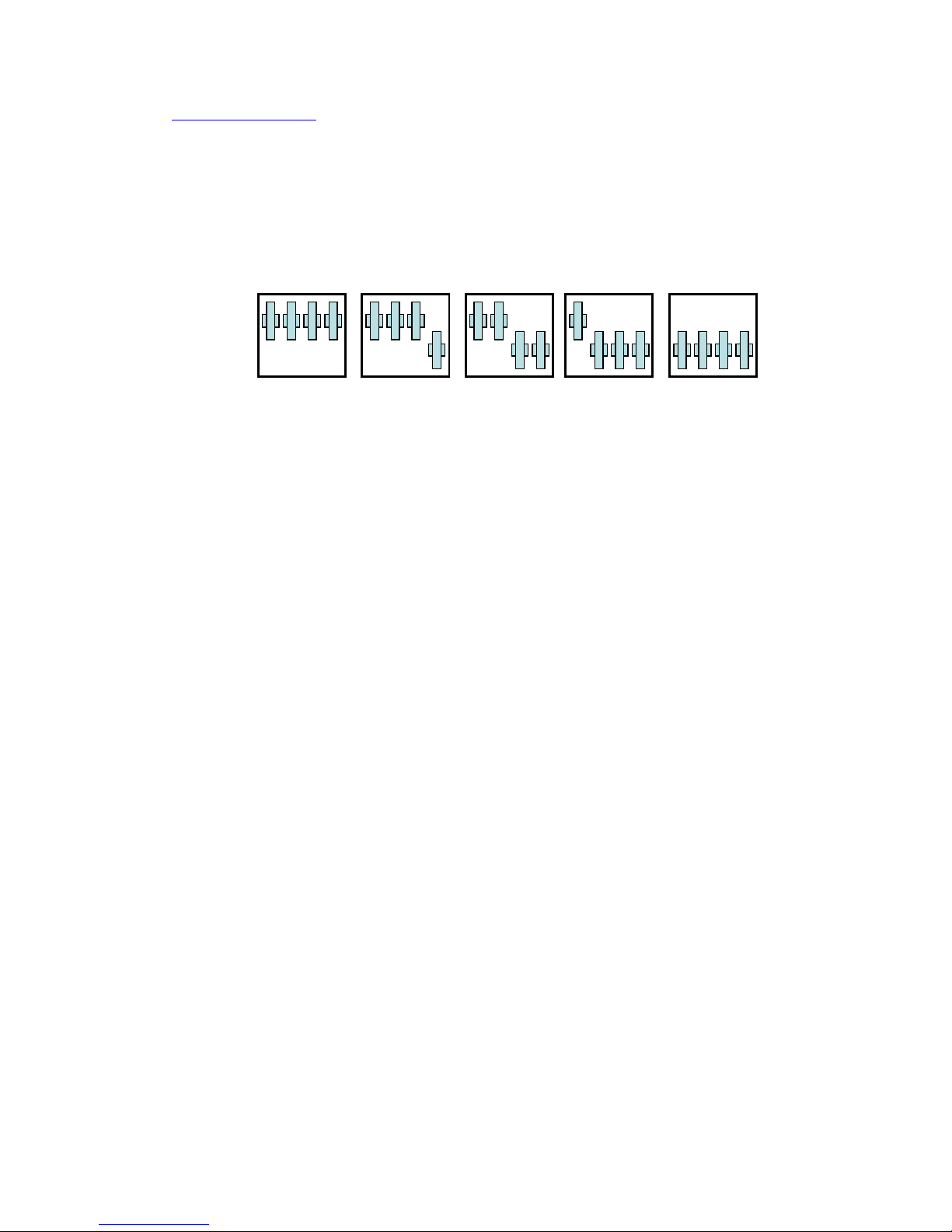
1. Set the DIP switches.
The DMG offers two button inputs and 6 relay outputs as default. Relay 2 is a toggle that is to say
it changes state from open to closed and vice versa each time it is commanded from the remote
telephone. All the other relays as 1 second closure only. The DIP switches can then be used to
‘trade’ button inputs for relay outputs as below:
A B C D
1 2 3 4
A B C DA B C DA B C D
1 2 3 4 1 2 3 4 1 2 3 4
Relays
123456 12456 1256 126 12
1 2 3 4
A B C D
12 123 1234 12345 123456
Buttons
A B C D
1 2 3 4
A B C DA B C DA B C D
1 2 3 4 1 2 3 4 1 2 3 4
Relays
123456 12456 1256 126 12
1 2 3 4
A B C D
12 123 1234 12345 123456
Buttons
The DMG reads the DIP switches each time it starts up and self configures accordingly. Do not set the
switches in any other combination as the DMG will not necessarily read them correctly. If you need to
re configure form one set to another, you must power cycle the DMG to make sure it will read the
new configuration.
2. Load the SIM with the numbers in use.
SIM cards can be programmed using a standard Cellular phone, setting the memory to use SIM only.
For Example in a Nokia Phone this is found under Names – Settings – Memory in Use where you can
select ‘SIM only’
Having done this key in the number you wish to assign to Button 1, use the full sequence that you
would ordinarily dial.
Save the number and give it a name. The names for your numbers need to follow the following rule.
For Button 1 the number MUST use the Name 1A (in Capitals). Button 2 the name 2A and so on for all
6 buttons. You must not add further characters to the name.
Note that unlike earlier versions of the DMG1, It does not matter in which order the phone numbers
are entered or where they are stored on the SIM.
NOTE: We have found that some recent phones will add extra invisible characters to the Name when
saving to sort the names into other categories eg Home, Work, Mobile etc. This will cause problems.
These are usually characterised by the DMG1 refusing to make outbound calls whilst still accepting
inbound.
There are several freestanding or USB SIM reader/writers on the market that do not suffer from this
and which can also make the pre-programming of the SIM quick and easy. As many installers carry a
Laptop as part of their installation equipment, a USB SIM reader/writer can be a very convenient
means of programming and one which will allow a copy of the stored data to be kept for maintenance
purposes.
Numbers can be loaded via SMS as described in Section 5.3 although this can be slow if there are
many to do.
If you do not wish to modify or extend the settings for the Call forwarding or call duration or activate
the SMS or Toll free calling option please continue otherwise see the notes in section 5.
Page 3
Genius Gate Systems Ltd
4 Wayside Green Woodcote Reading Berks RG8 0QJ
Directors: D.M.Pearson. M.J.Thornton. J.A.Pearson Registration No: 4557960 (England)
V.A.T.No: 815 9757 88
Page 3
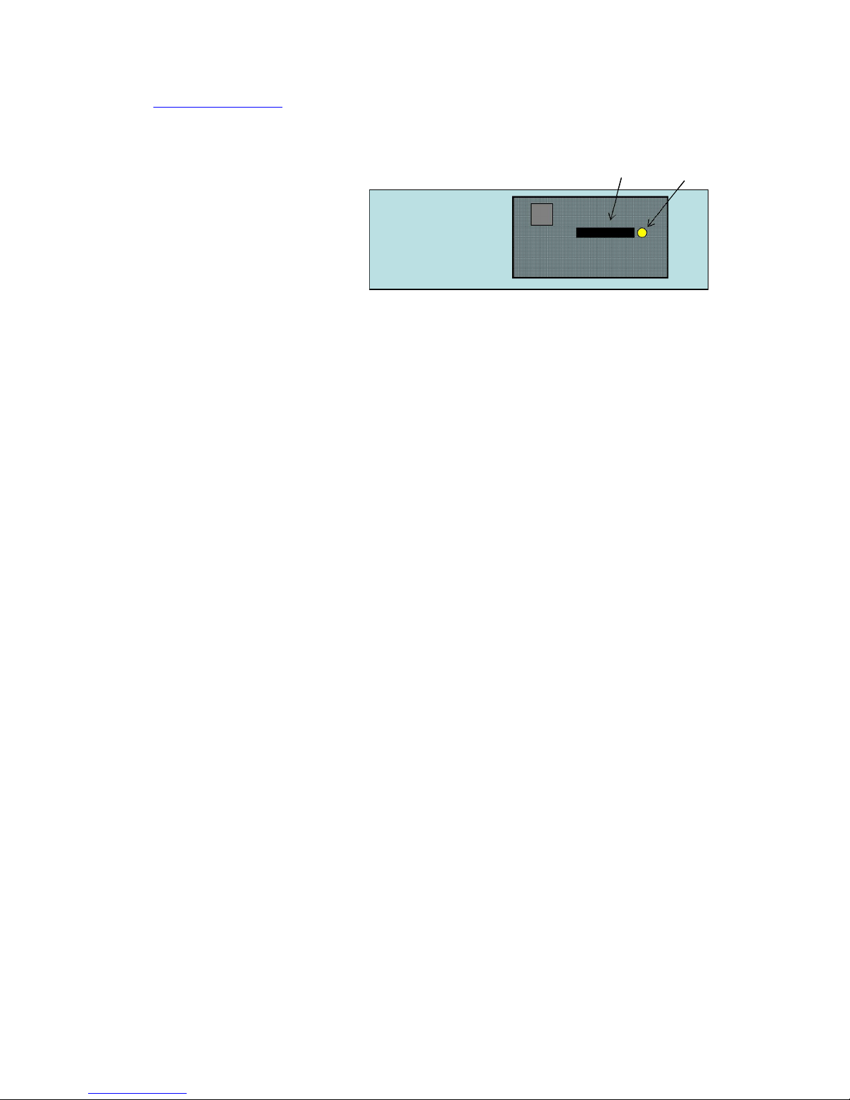
When finished remove the SIM (not forgetting to return the phone to its original memory setting) and
using the tip of a ballpoint or a similar small object eject the SIM tray from the top of the DMG at the
point shown by pressing the Yellow button as below:
SIM Tray
SIM Eject
button
SIM Tray
SIM Eject
button
3. Connect up the external components
Mount the DMG as desired and connect the antenna.
Note that the Antenna produces short range audio interference and should be kept at least 300mm
away from the audio gate panel if they are obliged to occupy the same cabinet.
Connect the Audio circuits using the terminals marked. The COMmon terminals for the Mic and
Speaker for the voice circuits are the Left Hand ones of each pair. These may be connected together
if needed but best audio interference rejection is obtained if they are connected together at the
Voice panel only.
Next connect the Button inputs to the terminal strip as indicated. Note The DMG Button inputs
respond to being grounded via a dry contact only.
Next connect the relay outputs to the external drive circuits. Remember that Relay 2 is a Toggle.
Diagrams are available for most common industry analogue panels and can be found on our website.
Please contact us if you have a different panel and we will advise on compatibility.
4. Test the system
Check all connections and once satisfied power up the DMG1and the Gate panel.
The Status indicator will start to flash quickly as the GSM unit tries to register with the network.
Once registration is complete the indicator will flash slowly (every 3 seconds).
NOTE the DMG will take approximately 80 seconds to complete its internal checks and read the data
stored on the SIM before it will respond.
With a mobile phone (or landline) call the phone number issued with the SIM. The DMG will answer
the call after 3 or 4 rings and issue a simple Dit-Dit-Dit Dee sound to the caller. The call will hold for
about 30 seconds as the internal countdown timer runs out, during which time the caller can operate
the relays by pressing button1 on the phone for relay 1, button 2 for relay 2 and so on. Each button
press will reset the countdown time to 30 seconds run time. Successful relay operation results in a
Dit-Dit-Dit-Dee sound being issued. The sound for relay 2 however also indicates the status of the
relay. Being a Dit-Dit-Dit-Dee-Dee as the relay closes and a Dit-Dit-Dit-Doh-Doh as it opens.
Let the call drop once proper operation is established and initiate outbound calls by pressing the gate
buttons to call the target numbers loaded into the SIM earlier. Once again check for proper
operation.
Page 4

Genius Gate Systems Ltd
4 Wayside Green Woodcote Reading Berks RG8 0QJ
Directors: D.M.Pearson. M.J.Thornton. J.A.Pearson Registration No: 4557960 (England)
V.A.T.No: 815 9757 88
Page 4
5. Advanced Features
5.1. Call Forwarding
How it works
When a button is pressed, say Button 1, The DMG1 will scan the SIM card for the name that begins
with 1A and call the number stored there. The call will ring until the call forward timer runs out. The
call is then automatically dropped and a new call set up to the Number stored at 1B. If there is no
number stored at 1B the DMG1 will call the number at 1A again. This will ring until the call is
answered or the DMG1 countdown timer runs out or in some cases the Network drops the call anyway.
This will be about 30 seconds. As network conditions are variable the number of rings for the first
number may vary a little over time.
Modifying the Settings.
The Call forward timer defaults to 1 second that is to say it is effectively disabled. The call duration
timer is 30 seconds. Both of these can be changed.
Usage suggestions
o With a single Number stored at 1A and no 1B the system will redial the number at 1A as is stated
above. If the call forward timer is set to about 15 seconds the effect is to give a 4 or 5 rings
followed by a short break when the phone will start ringing again. Many users find this provides a
form of distinctive ringing thus indicating a call from the gate. It can be useful to reduce the call
forwarding timer (to about 8 Seconds) to make the first ring only one or two.
o The call forwarding timer may be extended to any value up to 99 seconds if needed but it must
be noted that the default value was chosen to avoid the likelihood of a customers Voicemail
answering the call in which case the Second call will not occur.
o The call duration timer can also be increased from its default of 30 seconds up to 99 seconds if
more time is needed to answer the phone, perhaps for a landline in a large building. The 30
second default was chosen to keep call charges at a minimum as the call will not necessarily drop
if the remote number is a mobile when the remote party hangs up.
Changing the settings
If you want to change the timers you can do so by storing a name on the SIM card in the form
DAT4xxyy where xx or yy is a number of seconds. The value for xx is the time delay from the call
setup to the call forward trigger. The value for yy is the call duration timer and is optional. It is best
to store a dummy telephone number, say 1234 as some phones will not write a name to the SIM
properly without one and the DMG1 will be unable to read the call forwarding information.
Note: If you want to make the call forward less that 10 seconds you must enter a leading zero eg 07
for 7 seconds. Entering a value of less than 30 seconds for the call duration will not have any effect.
DAT must be in Capitals.
Examples:
Name
Effect
DAT415
15 second Call forward delay (about 5 rings), standard 30 second
call duration
DAT408
8 second call forward delay, standard 30 second call duration
DAT40845
8 second call forward delay, 45 second call duration
Page 5

Genius Gate Systems Ltd
4 Wayside Green Woodcote Reading Berks RG8 0QJ
Directors: D.M.Pearson. M.J.Thornton. J.A.Pearson Registration No: 4557960 (England)
V.A.T.No: 815 9757 88
Page 5
5.2. Toll free inbound Calling
How it works
You may store up to 20 numbers that the DMG1 will compare against the inbound Caller Line Identity
(CLI) when an inbound call is made. If it finds a match it will operate relay number 1 and drop the
call. Thus a caller who makes a speed dial call to the gate can open the gate without any call charges
and by only pressing one button on the phone keypad. It may be noted that Key 5 on most keypads is
easy to identlfy without looking as it generally has a raised dimples.
The Numbers are stored in the SIM by entering the name DATS (in capitals) and storing the number in
question against that name. If you want to store multiple numbers, you can store up to 20 in which
case you can extend the DATS name as DATS01, DATS02 DATS03 and so on for each number you store.
5.3. SMS Communications
The DMG can be contacted from a mobile using the Simple Messaging Service (SMS). To enable this,
the DMG1 uses a 4 Digit security site code. The default value for this is 1234. If you wish to use your
own code for added security you can give it you own value. The Code is any 4 digit number except it
may NOT start with a zero.
The Site Code is stored in the SIM by storing the Name DAT3xxxx (in capitals) where xxxx is the Site
code. As with call forwarding you should store a dummy number for this name, 1234 will do.
The DMG 1 can then be sent a standard type SMS message via its telephone number to which it will
reply.
As an example assume the Site code 1966 has been stored as DAT31966
The features then enabled are:
Inbound Message
Function
Result
DMQ1966
A status Query
DMG1 will collect the signal strength and reply.
Signal level should be above 12 units for stable
operation
DMR1966.1A
Read a number
DMG1 will search for a number against the reference
1A and report it.
DMW1966.5A!01999999999
Write a number
DMG1 will search for a number against the reference
5A and create or overwrite it and report the action.
DMS1996.1
Switch a relay
DMG1 will operate the relay 1 and report the action.
Note: The Syntax MUST be exactly as above. The number for the write command is in standard
national format
Version 3.6 August 2009
 Loading...