

Page 1

RAINBOW 524 C
RAINBOW 724 C
GIudA peR l’INstAllAtORe - GuIde fOR the INstAlleR
uIde pOuR l’INstAllAteuR - GuíA pARA el INstAlAdOR
leItfAdeN füR deN INstAllAteuR - GIds vOOR de INstAllAteuR
Page 2
ITALIANO
AVVERTENZE PER L’INSTALLATORE
OBBLIGHI GENERALI PER LA SICUREZZA
ATTENZIONE! È importante per la sicurezza delle persone seguire attentamente tutta
l’istruzione. Una errata installazione o un errato uso del prodotto può portare a
gravi danni alle persone.
Leggere attentamente le istruzioni prima di iniziare l’installazione del prodotto.
I materiali dell’imballaggio (plastica, polistirolo, ecc.) non devono essere lasciati alla
portata dei bambini in quanto potenziali fonti di pericolo.
Conservare le istruzioni per riferimenti futuri.
Questo prodotto è stato progettato e costruito esclusivamente per l’utilizzo indicato in
questa documentazione. Qualsiasi altro utilizzo non espressamente indicato potrebbe
pregiudicare l’integrità del prodotto e/o rappresentare fonte di pericolo.
GENIUS declina qualsiasi responsabilità derivata dall’uso improprio o diverso da quello
per cui l’automatismo è destinato.
Non installare l’apparecchio in atmosfera esplosiva: la presenza di gas o fumi infiammabili costituisce un grave pericolo per la sicurezza.
Gli elementi costruttivi meccanici devono essere in accordo con quanto stabilito dalle
Norme EN 12604 e EN 12605.
Per i Paesi extra-CEE, oltre ai riferimenti normativi nazionali, per ottenere un livello di
sicurezza adeguato, devono essere seguite le Norme sopra riportate.
GENIUS non è responsabile dell’inosservanza della Buona Tecnica nella costruzione
delle chiusure da motorizzare, nonché delle deformazioni che dovessero intervenire
nell’utilizzo.
L’installazione deve essere effettuata nell’osservanza delle Norme EN 12453 e EN 12445.
Il livello di sicurezza dell’automazione deve essere C+D.
Prima di effettuare qualsiasi intervento sull’impianto, togliere l’alimentazione elettrica
e scollegare le batterie.
Prevedere sulla rete di alimentazione dell’automazione un interruttore onnipolare con
distanza d’apertura dei contatti uguale o superiore a 3 mm. È consigliabile l’uso di un
magnetotermico da 6A con interruzione onnipolare.
Verificare che a monte dell’impianto vi sia un interruttore differenziale con soglia da
0,03 A.
Verificare che l’impianto di terra sia realizzato a regola d’arte e collegarvi le parti
metalliche della chiusura.
L’automazione dispone di una sicurezza intrinseca antischiacciamento costituita da un
controllo di coppia. E’ comunque necessario verificarne la sogli di intervento secondo
quanto previsto dalle Norme indicate al punto 10.
I dispositivi di sicurezza (norma EN 12978) permettono di proteggere eventuali aree
di pericolo da Rischi meccanici di movimento, come ad Es. schiacciamento, convogliamento, cesoiamento.
Per ogni impianto è consigliato l’utilizzo di almeno una segnalazione luminosa nonché
di un cartello di segnalazione fissato adeguatamente sulla struttura dell’infisso, oltre
ai dispositivi citati al punto “16”.
GENIUS declina ogni responsabilità ai fini della sicurezza e del buon funzionamento
dell’automazione, in caso vengano utilizzati componenti dell’impianto non di produzione GENIUS.
Per la manutenzione utilizzare esclusivamente parti originali GENIUS.
Non eseguire alcuna modifica sui componenti facenti parte del sistema d’automazione.
L’installatore deve fornire tutte le informazioni relative al funzionamento manuale
del sistema in caso di emergenza e consegnare all’Utente utilizzatore dell’impianto il
libretto d’avvertenze allegato al prodotto.
Non permettere ai bambini o persone di sostare nelle vicinanze del prodotto durante
il funzionamento.
L’applicazione non può essere utilizzata da bambini, da persone con ridotte capacità fisiche, mentali, sensoriali o da persone prive di esperienza o del necessario
addestramento.
Tenere fuori dalla portata dei bambini radiocomandi o qualsiasi altro datore di impulso,
per evitare che l’automazione possa essere azionata involontariamente.
Il transito tra le ante deve avvenire solo a cancello completamente aperto.
L’utente utilizzatore deve astenersi da qualsiasi tentativo di riparazione o d’intervento
e deve rivolgersi solo ed esclusivamente a personale qualificato GENIUS o centri
d’assistenza GENIUS.
Tutto quello che non è previsto espressamente in queste istruzioni non è permesso.
ENGLISH
IMPORTANT NOTICE FOR THE INSTALLER
GENERAL SAFETY REGULATIONS
ATTENTION! To ensure the safety of people, it is important that you read all the fol-
lowing instructions. Incorrect installation or incorrect use of the product could
cause serious harm to people.
Carefully read the instructions before beginning to install the product.
Do not leave packing materials (plastic, polystyrene, etc.) within reach of children
as such materials are potential sources of danger.
Store these instructions for future reference.
This product was designed and built strictly for the use indicated in this documentation.
Any other use, not expressly indicated here, could compromise the good condition/
operation of the product and/or be a source of danger.
GENIUS declines all liability caused by improper use or use other than that for which
the automated system was intended.
Do not install the equipment in an explosive atmosphere: the presence of inflammable
gas or fumes is a serious danger to safety.
The mechanical parts must conform to the provisions of Standards EN 12604 and EN
12605.
For non-EU countries, to obtain an adequate level of safety, the Standards mentioned
above must be observed, in addition to national legal regulations.
GENIUS is not responsible for failure to observe Good Technique in the construction
of the closing elements to be motorised, or for any deformation that may occur
during use.
The installation must conform to Standards EN 12453 and EN 12445. The safety level of
the automated system must be C+D.
Before attempting any job on the system, cut out electrical power and disconnect
the batteries.
The mains power supply of the automated system must be fitted with an all-pole
switch with contact opening distance of 3mm or greater. Use of a 6A thermal breaker
with all-pole circuit break is recommended.
Make sure that a differential switch with threshold of 0.03 A is fitted upstream of the
system.
Make sure that the earthing system is perfectly constructed, and connect metal parts
of the means of the closure to it.
The automated system is supplied with an intrinsic anti-crushing safety device consisting
of a torque control. Nevertheless, its tripping threshold must be checked as specified
1.
2.
3.
4.
5.
6.
7.
8.
9.
10.
11.
12.
13.
14.
15.
16.
17.
18.
19.
20.
21.
22.
23.
24.
25.
26.
27.
1.
2.
3.
4.
5.
6.
7.
8.
9.
10.
11.
12.
13.
14.
15.
in the Standards indicated at point 10.
The safety devices (EN 12978 standard) protect any danger areas against mechanical
movement Risks, such as crushing, dragging, and shearing.
Use of at least one indicator-light is recommended for every system, as well as a
warning sign adequately secured to the frame structure, in addition to the devices
mentioned at point “16”.
GENIUS declines all liability as concerns safety and efficient operation of the automated
system, if system components not produced by GENIUS are used.
For maintenance, strictly use original parts by GENIUS.
Do not in any way modify the components of the automated system.
The installer shall supply all information concerning manual operation of the system
in case of an emergency, and shall hand over to the user the warnings handbook
supplied with the product.
Do not allow children or adults to stay near the product while it is operating.
The application cannot be used by children, by people with reduced physical, mental,
sensorial capacity, or by people without experience or the necessary training.
Keep remote controls or other pulse generators away from children, to prevent the
automated system from being activated involuntarily.
Transit through the leaves is allowed only when the gate is fully open.
The User must not in any way attempt to repair or to take direct action and must solely
contact qualified GENIUS personnel or GENIUS service centres.
Anything not expressly specified in these instructions is not permitted.
FRANÇAIS
CONSIGNES POUR L’INSTALLATEUR
RÈGLES DE SÉCURITÉ
ATTENTION! Il est important, pour la sécurité des personnes, de suivre à la lettre
toutes les instructions. Une installation erronée ou un usage erroné du produit
peut entraîner de graves conséquences pour les personnes.
Lire attentivement les instructions avant d’installer le produit.
Les matériaux d’emballage (matière plastique, polystyrène, etc.) ne doivent pas être
laissés à la portée des enfants car ils constituent des sources potentielles de danger.
Conserver les instructions pour les références futures.
Ce produit a été conçu et construit exclusivement pour l’usage indiqué dans cette
documentation. Toute autre utilisation non expressément indiquée pourrait compromettre l’intégrité du produit et/ou représenter une source de danger.
GENIUS décline toute responsabilité qui dériverait d’usage impropre ou différent de
celui auquel l’automatisme est destiné.
Ne pas installer l’appareil dans une atmosphère explosive: la présence de gaz ou de
fumées inflammables constitue un grave danger pour la sécurité.
Les composants mécaniques doivent répondre aux prescriptions des Normes EN
12604 et EN 12605.
Pour les Pays extra-CEE, l’obtention d’un niveau de sécurité approprié exige non
seulement le respect des normes nationales, mais également le respect des Normes
susmentionnées.
GENIUS n’est pas responsable du non-respect de la Bonne Technique dans la construction des fermetures à motoriser, ni des déformations qui pourraient intervenir lors
de l’utilisation.
L’installation doit être effectuée conformément aux Normes EN 12453 et EN 12445. Le
niveau de sécurité de l’automatisme doit être C+D.
Couper l’alimentation électrique et déconnecter la batterie avant toute intervention
sur l’installation.
Prévoir, sur le secteur d’alimentation de l’automatisme, un interrupteur omnipolaire
avec une distance d’ouverture des contacts égale ou supérieure à 3 mm. On recommande d’utiliser un magnétothermique de 6A avec interruption omnipolaire.
Vérifier qu’il y ait, en amont de l’installation, un interrupteur différentiel avec un seuil
de 0,03 A.
Vérifier que la mise à terre est réalisée selon les règles de l’art et y connecter les pièces
métalliques de la fermeture.
L’automatisme dispose d’une sécurité intrinsèque anti-écrasement, formée d’un contrôle du couple. Il est toutefois nécessaire d’en vérifier le seuil d’intervention suivant les
prescriptions des Normes indiquées au point 10.
Les dispositifs de sécurité (norme EN 12978) permettent de protéger des zones éventuellement dangereuses contre les Risques mécaniques du mouvement, comme
l’écrasement, l’acheminement, le cisaillement.
On recommande que toute installation soit doté au moins d’une signalisation lumineuse, d’un panneau de signalisation fixé, de manière appropriée, sur la structure de
la fermeture, ainsi que des dispositifs cités au point “16”.
GENIUS décline toute responsabilité quant à la sécurité et au bon fonctionnement
de l’automatisme si les composants utilisés dans l’installation n’appartiennent pas à
la production GENIUS.
Utiliser exclusivement, pour l’entretien, des pièces GENIUS originales.
Ne jamais modifier les composants faisant partie du système d’automatisme.
L’installateur doit fournir toutes les informations relatives au fonctionnement manuel du
système en cas d’urgence et remettre à l’Usager qui utilise l’installation les “Instructions
pour l’Usager” fournies avec le produit.
Interdire aux enfants ou aux tiers de stationner près du produit durant le fonctionnement.
Ne pas permettre aux enfants, aux personennes ayant des capacités physiques,
mentales et sensorielles limitées ou dépourvues de l’expérience ou de la formation
nécessaires d’utiliser l’application en question.
Eloigner de la portée des enfants les radiocommandes ou tout autre générateur
d’impulsions, pour éviter tout actionnement involontaire de l’automatisme.
Le transit entre les vantaux ne doit avoir lieu que lorsque le portail est complètement
ouvert.
L’utilisateur doit s’abstenir de toute tentative de réparation ou d’intervention et doit
s’adresser uniquement et exclusivement au personnel qualifié GENIUS ou aux centres
d’assistance GENIUS.
Tout ce qui n’est pas prévu expressément dans ces instructions est interdit.
ESPAÑOL
ADVERTENCIAS PARA EL INSTALADOR
REGLAS GENERALES PARA LA SEGURIDAD
ATENCION! Es sumamente importante para la seguridad de las personas seguir
atentamente las presentes instrucciones. Una instalación incorrecta o un uso
impropio del producto puede causar graves daños a las personas.
Lean detenidamente las instrucciones antes de instalar el producto.
Los materiales del embalaje (plástico, poliestireno, etc.) no deben dejarse al alcance
de los niños, ya que constituyen fuentes potenciales de peligro.
Guarden las instrucciones para futuras consultas.
Este producto ha sido proyectado y fabricado exclusivamente para la utilización
indicada en el presente manual. Cualquier uso diverso del previsto podría perjudicar
el funcionamiento del producto y/o representar fuente de peligro.
16.
17.
18.
19.
20.
21.
22.
23.
24.
25.
26.
27.
1.
2.
3.
4.
5.
6.
7.
8.
9.
10.
11.
12.
13.
14.
15.
16.
17.
18.
19.
20.
21.
22.
23.
24.
25.
26.
27.
1.
2.
3.
4.
Page 3

RAINBOW 524 C- RAINBOW 724 C
ITALIANO
Guida per l’installatore
Pagina 1
DICHIARAZIONE CE DI CONFORMITÁ
Fabbricante: GENIUS S.p.A.
Indirizzo: Via Padre Elzi, 32 - 24050 - Grassobbio- Bergamo - ITALIA
Dichiara che: L’operatore mod. RAINBOW 524 C - RAINBOW 724 C
è costruito per essere incorporato in una macchina o per essere assemblato con altri macchinari per costituire una macchina ai sensi
della Direttiva 2006/42/CE;
è conforme ai requisiti essenziali di sicurezza delle seguenti altre direttive CEE:
2006/95/CE direttiva Bassa Tensione.
2004/108/CE direttiva Compatibilità elettromagnetica.
Inoltre dichiara che non è consentito mettere in servizio il macchinario fino a che la macchina in cui sarà incorporato o di cui diverrà
componente sia stata identificata e ne sia stata dichiarata la conformità alle condizioni della Direttiva 2006/42/CEE e successive
modifiche.
Grassobbio, 01 Febbraio 2010
L’Amministratore Delegato
D. Gianantoni
•
•
•
•
•
Note per la lettura dell’istruzione
Leggere completamente questo manuale di installazione prima di iniziare l’installazione del prodotto.
Il simbolo evidenzia note importanti per la sicurezza delle persone e l’integrità dell’automazione.
Il simbolo richiama l’attenzione su note riguardanti le caratteristiche od il funzionamento del prodotto.
INDICE
NOTE IMPORTANTI PER L’INSTALLATORE pag.2
1. DESCRIZIONE pag.2
1.1 CARATTERISTICHE TECNICHE pag.2
2. PREDISPOSIZIONI ELETTRICHE (Impianto standard) pag.3
3. INSTALLAZIONE DELL’AUTOMAZIONE pag.3
3.1. VERIFICHE PRELIMINARI pag.3
3.2. MURATURA DELLA PIASTRA DI FONDAZIONE pag.3
3.3. INSTALLAZIONE MECCANICA pag.3
3.4. MONTAGGIO DELL’ASTA pag.3
3.5. INSTALLAZIONE E REGOLAZIONE DELLA MOLLA DI BILANCIAMENTO pag.3
3.6. REGOLAZIONE DEGLI ARRESTI MECCANICI pag.3
3.7. REGOLAZIONE DEI FINECORSA pag.3
4. INSTALLAZIONE DEGLI ACCESSORI (Optional) pag.4
4. COLLEGAMENTI ELETTRICI pag.4
5. MESSA IN FUNZIONE pag.4
6. FUNZIONAMENTO MANUALE pag.4
7. RIPRISTINO DEL FUNZIONAMENTO NORMALE pag.4
8. MANUTENZIONE pag.4
9. RIPARAZIONI pag.4
10. ACCESSORI pag.4
10.1. KIT ARTICOLAZIONE pag.4
10.2. KIT SIEPE pag.4
10.3. PIEDINO D’ESTREMITÀ pag.4
10.4. SUPPORTO A FORCELLA pag.4
10.5. SUPPORTO FOTOCELLULA pag.5
10.5. CORDONE LUMINOSO PER MONTANTE pag.5
10.6. CORDONE LUMINOSO PER ASTA pag.5
10.7. KIT BATTERIE pag.5
Page 4
RAINBOW 524 C - RAINBOW 724 C
ITALIANO
Guida per l’installatore
Pagina 2
Vi ringraziamo per aver scelto un nostro prodotto. GENIUS è certa
che da esso otterrete tutte le prestazioni necessarie al Vostro impiego. Tutti i nostri prodotti sono frutto di una pluriennale esperienza
nel campo degli automatismi, rafforzata dal fatto di essere parte
del gruppo leader mondiale del settore.
Nel centro del manuale è stato realizzato un opuscolo stac-
cabile con tutte le immagini per l’installazione.
Le automazioni della famiglia RAINBOW sono barrire elettromeccaniche progettate e realizzate per il controllo di accessi veicolari.
La centrale è posizionata nella parte superiore dell’automazione
e può essere ruotata per facilitare le operazioni di cablaggio e
settaggio della stessa. Sul cofano sono presenti le predisposizione per l’alloggiamento delle fotocellule (Orion) e del selettore
a chiave (Quick). Inoltre sia sul cofano che sulle sbarre vi è la
possibilità di installare dei cordoni luminosi, sostituendo il classico
lampeggiante.
Grazie alle varie tipologie di aste disponibili possono essere utilizzate
nei più svariati tipi di accessi, da un minimo di 3 metri sino ad un
massimo di 7 metri.
Un comodo dispositivo di sblocco, protetto con chiave personalizzata, permette di movimentare manualmente l’asta in caso di
mancanza di alimentazione.
Grazie all’utilizzo di motori a 24V ed all’encoder, fornito di serie,
tutte le automazioni della famiglia RAINBOW offrono elevate garanzie di sicurezza.
NOTE IMPORTANTI PER L’INSTALLATORE
Prima di iniziare l’installazione dell’operatore leggere completamente il presente manuale.
Conservare il manuale per eventuali riferimenti futuri.
Il corretto funzionamento e le caratteristiche tecniche dichiarate
si ottengono solo rispettando le indicazioni riportate in questo
manuale e con accessori e dispositivi di sicurezza GENIUS.
La mancanza di un dispositivo di frizione meccanica richiede,
per garantire un adeguato grado di sicurezza dell’automazione,
l’impiego di una centrale di comando con un dispositivo di frizione
elettronica regolabile.
L’automazione è stata progettata e costruita per controllare l’accesso veicolare. Evitare qualsiasi altro diverso utilizzo.
L’operatore non può essere utilizzato per movimentare uscite
di sicurezza o cancelli installati su percorsi d’emergenza (vie di
fuga).
Non transitare con l’asta in movimento.
Tutto quello che non è espressamente indicato in questo manuale
non è permesso.
1. DESCRIZIONE
Con riferimento alla figura 1:
Pos. Descrizione
a
Montante
b
Portella
c
Piastra di fondazione (venduta separatamente)
d
Carter di copertura
e
Contenitore centrale di comando
f
Carter di copertura attacco asta
g
Asta (venduta separatamente in base alle esigenze
installative)
h
Molla di bilanciamento (venduta separatamente, numero e tipologia in base al tipo di asta ed accessori
applicati)
i
Motoriduttore
j
Encoder
k
Finecorsa chiusura / apertura
l
Finecorsa di sicurezza
m
Bordo rosso (copertura per cordone luminoso optional)
n
Dispositivo di sblocco
o
Vano per batterie tampone (non fornite)
•
•
•
•
•
•
•
•
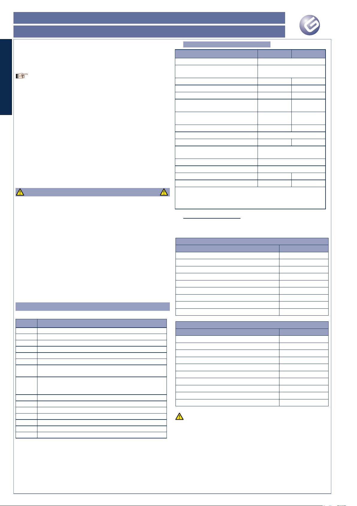
1.1 CARATTERISTICHE TECNICHE
Modello RAINBOW 524 C 724 C
Tensione d'alimentazione 230Vac 50Hz / 115Vac 60Hz
Tensione d’alimentazione motore
(Vdc)
24
Potenza massima in spunto (W) 280 480
Potenza nominale motore (W) 160 220
Coppia max. a 24Vdc (Nm) 140 370
Coppia nominale di funzionamento
(Nm)
75 140
Tempo nominale apertura / chiusura
(sec)
a
da 4 a 8 da 7 a 11
Lunghezza massima asta (m)
b
5 7
Tipo e frequenza d’utilizzo a 20°C Semi intensivo
Cicli massimi giornalieri (cicli) 1000 500
Temperatura di funzionamento
(°C)
-20 +55
Rumorosità (dBA) <70
Grado di protezione IP 54
Peso operatore (Kg) 66 72
Dimensioni Vedi figura 2 Vedi figura 3
a Tempo in funzione del tipo di rallentamento impostato.
b Lunghezza riferita alla luce di passaggio, lunghezza asta
+400mm circa
1.1.1. Vita del prodotto
Nelle tabelle che seguono è riportata la vita del prodotto, espressa
in numero di cicli, in funzione della tipologia di asta scelta ed agli
accessori applicati ad essa:
RAINBOW 524 C
Asta ed accessorio Vita (N° cicli)
3 metri 1.500.000
4 metri 1.300.000
5 metri 1.100.000
3 metri con piedino 1.300.000
4 metri con piedino 1.100.000
5 metri con piedino 800.000
3 metri con 2 metri di siepe 1.300.000
4 metri con 3 metri di siepe 1.100.000
5 metri con 4 metri di siepe 800.000
RAINBOW 724 C
Asta ed accessorio Vita (N° cicli)
4 metri 1.300.000
5 metri 1.100.000
6 metri 850.000
7 metri 500.000
4 metri con piedino 1.100.000
5 metri con piedino 850.000
6.5 metri con piedino 500.000
4 metri con 2 metri di siepe 1.100.000
5 metri con 3.5 metri di siepe 850.000
6.5 metri con 5 metri di siepe 500.000
La vita del prodotto è stata calcolata ad una temperatura
di 20°C su operatori installati in modo corretto, come da
specifiche riportate nelle istruzioni.
Page 5
RAINBOW 524 C- RAINBOW 724 C
ITALIANO
Guida per l’installatore
Pagina 3
2. PREDISPOSIZIONI ELETTRICHE
(Impianto standard)
Con riferimento alla figura 4:
Pos. Descrizione Sezione cavi
a
Operatore (alimentazione elettrica) 3x1.5 mm
2
b
Fotocellula TX 2x0.5 mm
2
c
Fotocellula RX 4x0.5 mm
2
d
Selettore a chiave 2x0.5 mm
2
Per la messa in opera dei cavi utilizzare adeguati tubi rigidi
e/o flessibili
Separare sempre i cavi di collegamento degli accessori a
bassa tensione da quelli di alimentazione. Per evitare possibili
interferenze utilizzare guaine separate.
3. INSTALLAZIONE DELL’AUTOMAZIONE
3.1. VERIFICHE PRELIMINARI
Per la sicurezza e per il corretto funzionamento dell’automazione
verificare l’esistenza dei seguenti requisiti:
La sbarra nel suo movimento non deve assolutamente incontrare
ostacoli o cavi aerei.
Le caratteristiche del terreno devono garantire un’adeguata
tenuta del plinto di fondazione.
Nella zona di scavo del plinto non devono essere presenti tubazioni o cavi elettrici.
Se il corpo della barriera si trova esposto al passaggio di veicoli
prevedere, dove possibile, adeguate protezioni contro urti accidentali.
Verificare l’esistenza di un’efficiente presa di terra per il collegamento del montante.
3.2. MURATURA DELLA PIASTRA DI FONDAZIONE
Assemblare la piastra di fondazione come indicato in figura 5.
Eseguire un plinto di fondazione come indicato in figura 6.
Le dimensioni del plinto devono essere idonee al tipo di instal-
lazione ed al tipo di terreno.
Murare la piastra di fondazione come indicato in figura 6, prevedendo una o più guaine per il passaggio dei cavi elettrici.
La parte bombata della piastra di fondazione deve essere
rivolta verso l’interno del passaggio da automatizzare.
Verificare la perfetta orizzontalità della piastra con una livella.
Attendere che il cemento faccia presa.
3.3. INSTALLAZIONE MECCANICA
Rimuovere dalla piastra di fondazione i 4 dadi superiori.
Rimuovere le due viti di fissaggio del carter superiore, vedi Fig.
7, rif. a.
Inserire la chiave di sblocco nella serratura del carter, Fig. 8, e
ruotarla in senso orario sino al suo arresto.
Mantenendo la chiave in questa posizione rimuovere il carter
superiore, Fig. 8.
Rimuovere la portella come indicato in fig. 9.
Posizionare il montante sui quattro tiranti filettati come indicato
in fig. 10 e stringere i quattro dadi di fissaggio.
Predisporre l’automazione per il funzionamento manuale, vedi
paragrafo 6
Posizionare l’asta porta-molla, Fig. 11 rif. a, in posizione orizzontale.
Fissare il piatto porta-molla, come indicato in figura 12, in base
alla tipologia della chiusura:
se l’asta scende a sinistra del montante, installazione destra, il
piatto deve essere fissato sul perno b di figura 11.
se l’asta scende a destra del montante, installazione sinistra,
il piatto deve essere fissato sul perno c di figura 11.
Ruotare il piatto porta-molla nella posizione indicata in fig. 13,
a seconda del tipo d’installazione, Dx o SX.
Nella parte anteriore dell’automazione posizionare il piatto porta-asta mantenendolo in posizione orizzontale, Fig. 14.
Per il modello RAINBOW 724 C prestare attenzione all’orien-
tamento dei fori evidenziati in Fig. 14 rif. a, i fori si devono
trovare nella pare superiore del piatto.
Fissare il piatto porta asta con l’apposita vite e rondella, Fig.
15.
•
•
•
•
•
1.
2.
3.
4.
5.
1.
2.
3.
4.
5.
6.
7.
8.
9.
•
•
10.
11.
12.
3.4. MONTAGGIO DELL’ASTA
Per il montaggio dell’asta è opportuno tenere presente che:
Il bordo in gomma, con l’asta in posizione di chiusura, deve essere
rivolto verso il terreno.
Il foro presente sull’asta deve essere accoppiato al perno che
esce dal piatto di trascinamento.
Procedere quindi come indicato in fig. 16.
Posizionare l’asta sul perno centrale con il bordo in gomma
rivolto verso il basso.
Posizionare la tasca di fissaggio, fig. 16 rif. a, e fissare con le viti
in dotazione.
Fare attenzione all’orientamento dei fori evidenziati, fig. 16
rif. b, con i relativi fori sulla piastra porta-asta.
Assemblare il carter di copertura come indicato in figura 17,
a seconda del tipo di automazione e di installazione, sinistra
o destra.
Fissare il carter di copertura come indicato in fig. 18.
3.5. INSTALLAZIONE E REGOLAZIONE DELLA MOLLA DI
BILANCIAMENTO
L’automazione necessita, per il corretto funzionamento, di una o
due molle di bilanciamento che devono essere ordinate a parte
in base al modello dell’automazione, alla tipologia di asta ed agli
eventuali accessori scelti.
Per il montaggio e la regolazione della molla seguire le seguenti
indicazioni:
Portare la sbarra in posizione verticale e predisporre l’automazione per il normale funzionamento, vedi paragrafo 7, assicurandosi
che l’asta non possa muoversi manualmente.
Posizionare la molle o le molle nel piatto porta-molla come
indicato in fig. 19.
All’altra estremità della molla posizionare l’altro piatto portamolla ed il relativo tirante, fig. 20 rif. a e b e fissare il tutto
nell’apposito foro presente sul montante. Posizionare il dado di
fissaggio, fig. 20 rif. c.
Avvitare il dado, fig. 20 rif. c, fino a recuperare completamente
i giochi della molla.
Predisporre l’automazione per il funzionamento manuale agendo sul dispositivo di sblocco come indicato nel paragrafo 6.
Agendo sul dado inferiore, Fig. 20 rif. c, iniziare a mettere in
tensione la molla.
La molla è tensionata correttamente quando, posizionado
l’asta a 45° questa rimane ferma.
Una volta terminata la regolazione della molla bloccare la posizione del tirante stringendo il controdado fig. 20 rif. d.
3.6. REGOLAZIONE DEGLI ARRESTI MECCANICI
Nella parte superiore del montante sono presenti due arresti meccanici, Fig. 21 rif. a e b.
Per regolare la posizione degli arresti agire come di seguito:
Portare manualmente l’asta in posizione di chiusura.
Allentare i dadi di bloccaggio, fig. 21 rif c.
Agire sulla testa della vite sino a portare l’asta in posizione
orizzontale.
Stringere il dado di fissaggio.
Portare l’asta in posizione verticale ed agire in modo analogo
sull’altro arresto meccanico.
È consigliato ingrassare periodicamente i due arresti mec-
canici.
3.7. REGOLAZIONE DEI FINECORSA
Sull’automazione sono presenti due finecorsa per identificare la
posizione dell’asta, aperta o chiusa, Fig. 22.
L’automazione viene fornita con i finecorsa predisposti per una
installazione sinistra della sbarra.
Per regolare la posizione delle camme agire come di seguito:
Portare manualmente l’asta in posizione di chiusura.
Ruotare la camma, fig. 22 rif. a, sino a quando non si avverte
l’intervento del finecorsa.
Far avanzare leggermente la camma.
Il finecorsa deve intervenire prima dell’arresto meccanico.
Bloccare la posizione della camma serrando la relativa vite.
Portare l’asta in posizione di apertura.
Ruotare la camma, fig. 22 rif. b, sino a quando non si avverte
l’intervento del finecorsa.
Far avanzare leggermente la camma.
Il finecorsa deve intervenire prima dell’arresto meccanico.
•
•
1.
2.
3.
4.
1.
2.
3.
4.
5.
6.
6.
1.
2.
3.
4.
5.
1.
2.
3.
4.
5.
6.
7.
Page 6
RAINBOW 524 C - RAINBOW 724 C
ITALIANO
Guida per l’installatore
Pagina 4
Bloccare la posizione della camma serrando la relativa vite.
Nel caso di installazioni destre è necessario invertire i fili dei
finecorsa collegati in centrale, vedi istruzioni apparecchiatura elettronica.
Ribloccare l’automazione come descritto nel paragrafo 7.
4. INSTALLAZIONE DEGLI ACCESSORI (Optional)
Sul montante dell’automazione sono stati predisposti una serie di
fori per agevolare le operazioni di fissaggio di eventuali accessori
come fotocellule (Orion) e selettore a chiave (Quick).
Nella figura 23 sono raffigurati tutti gli accessori che è possibile
applicare al cofano dell’automazione.
Inoltre sia ai lati del montante che su tutta la lunghezza della sbarra
è possibile installare dei dispositivi di segnalazione luminosa.
Per il fissaggio dei singoli accessori seguire quanto indicato nelle
relative istruzioni.
4. COLLEGAMENTI ELETTRICI
Prevedere sulla rete di alimentazione dell’automazione un
interruttore onnipolare con distanza d’apertura dei contatti
uguale o superiore a 3 mm. È consigliabile l’uso di un magnetotermico da 6A con interruzione onnipolare.
Verificare che a monte dell’impianto vi sia un interruttore dif-
ferenziale con soglia da 0,03 A.
Terminato il montaggio e la regolazione della parte meccanica
dell’automazione si può procedere con il collegamento della rete
di alimentazione e di tutti gli accessori installati.
Per il collegamento del cavo di alimentazione è necessario aprire
il foro prefatturato presente sulla scatola centrale, fig. 24 rif. a, e
montare il pressacavo M16x1.5 in dotazione.
All’interno del montante è stata predisposta una canalina
per il passaggio dei cavi.
Il cavo di alimentazione deve entrare in centrale attraverso
il suo pressacavo dedicato.
Per il collegamento in centrale della linea d’alimentazione
e degli accessori installati fare riferimento alle istruzioni della
centrale di comando.
La centrale di comando è stata posizionata su di un supporto
orientabile, fig. 25. Questo permette di agevolare le operazioni di
cablaggio e programmazione della centrale stessa.
5. MESSA IN FUNZIONE
Riposizionare la portella come indicato in fig. 26 ed alimentare
il sistema.
Verificare lo stato dei led di segnalazione sulla centrale.
Eseguire la procedura di programmazione della centrale in base
alle proprie esigenze.
Eseguire una verifica funzionale di tutti gli accessori collegati,
prestando particolare attenzione ai dispositivi di sicurezza.
Chiudere il contenitore della centrale e posizionarla orizzontalmente.
Riposizionare il carter di copertura superiore come indicato in
fig. 27.
Istruire l’utilizzatore finale sul corretto funzionamento dell’automazione,
Illustrare le operazioni di sblocco e blocco dell’automazione.
Consegnare il fascicolo “Istruzioni per l’uso”, fascicolo staccabile
nel centro del manuale, e compilare il registro di manutenzione
allegato.
6. FUNZIONAMENTO MANUALE
Nel caso si renda necessario movimentare manualmente l’asta
a causa di disservizio dell’automazione o mancanza della rete
elettrica agire come di seguito:
Togliere tensione all’impianto agendo sull’interruttore differen-
ziale a monte dell’impianto.
Inserire la chiave nel dispositivo di sblocco e ruotarla in senso
orario sino al suo arresto, come indicato in fig. 28 rif. a.
Ruotare il dispositivo di sblocco in senso orario sino al suo arresto,
fig. 28 rif. b.
Muovere manualmente l’asta, fig. 28 rif. c.
7. RIPRISTINO DEL FUNZIONAMENTO NORMALE
Per evitare che un impulso involontario possa mettere in
funzione l’automazione, prima di ripristinare il normale funzionamento assicurarsi che l’impianto non sia alimentato
8.
9.
•
•
•
•
•
•
•
•
•
•
•
•
agendo sull’interruttore differenziale.
Ruotare il dispositivo di sblocco in senso antiorario sino al suo
arresto, Fig. 29 rif. a.
Ruotare la chiave in senso antiorario sino al suo arresto ed estrarla,
fig. 29 rif b.
Muovere manualmente l’asta sino al suo arresto, fig. 29 rif. c.
Ripristinare tensione all’impianto.
8. MANUTENZIONE
Al fine di assicurare nel tempo un corretto funzionamento ed un
costante livello di sicurezza eseguire, con cadenza semestrale, un
controllo generale dell’impianto prestando particolare attenzione
ai dispositivi di sicurezza. Nel fascicolo “Istruzioni per l’uso” è stato
predisposto un modulo per la registrazione degli interventi.
Ogni operazione di manutenzione od ispezione dell’operatore
deve avvenire dopo aver tolto tensione all’impianto e con
l’asta in posizione verticale.
Per il corretto funzionamento della barriera è consigliabile sostituire
periodicamente la molla o le molle di bilanciamento. Nella tabella
che segue è riportata la vita della molla in funzione del tipo di
automazione e di molla utilizzata:
Tipo di molla RAINBOW 524 C RAINBOW 724 C
Molla Strong 500.000 cicli 200.000 cicli
Molla Soft 500.000 cicli 350.000 cicli
Per rimuovere in piena sicurezza la molla o le molle di bilanciamento
seguire la procedura sotto descritta:
Togliere tensione all’impianto.
Predisporre l’operatore per il funzionamento manuale, portare
l’asta in posizione verticale e ribloccare l’operatore assicurandosi che non si possa muovere manualmente.
Rimuovere il carter superiore e la portella.
A questo punto è possibile rimuovere le molle di bilanciamen-
to.
Nel caso sia necessario rimuovere l’asta per operazioni di manutenzione è necessario seguire la seguente procedura:
Rimuovere le molle di bilanciamento come descritto in prece-
denza.
Predisporre l’operatore per il funzionamento manuale e portare
l’asta in posizione orizzontale.
A questo punto è possibile procedere alla rimozione dell’asta.
L’asta può essere rimossa solo dopo aver rimosso le molle di
bilanciamento.
9. RIPARAZIONI
L’utente utilizzatore deve astenersi da qualsiasi tentativo di riparazione o d’intervento e deve rivolgersi solo ed esclusivamente a
personale qualificato GENIUS o centri d’assistenza GENIUS.
10. ACCESSORI
10.1. KIT ARTICOLAZIONE
Il kit articolazione, fig. 30, è stato creato per articolare l’asta rigida
permettendone l’installazione in luoghi coperti.
L’utilizzo del kit articolazione comporta un adattamento della
molla di bilanciamento.
10.2. KIT SIEPE
Il kit siepe, fig. 31, aumenta la visibilità della sbarra. Il kit è disponibile
in lunghezze da 2 metri.
L’installazione del kit siepe comporta un adattamento della
molla di bilanciamento.
10.3. PIEDINO D’ESTREMITÀ
Il piedino d’estremità, fig. 32, permette l’appoggio dell’asta in
chiusura evitando eventuali flessioni del profilo verso il basso.
L’utilizzo del piedino d’estremità comporta un adattamento
della molla di bilanciamento.
10.4. SUPPORTO A FORCELLA
Il supporto a forcella, fig. 33, assolve a due funzioni:
evita che l’asta in posizione di chiusura si pieghi o si tranci per
effetto di sollecitazioni esterne.
permette l’appoggio dell’asta in posizione di chiusura evitando
eventuali flessioni.
L’utilizzo del supporto a forcella non richiede nessun adat-
tamento della molla di bilanciamento.
•
•
•
•
1.
2.
3.
4.
1.
2.
3.
•
•
Page 7

RAINBOW 524 C- RAINBOW 724 C
ITALIANO
Guida per l’installatore
Pagina 5
10.5. SUPPORTO FOTOCELLULA
Il supporto fotocellula, fig. 34, permette di posizionare una coppia
di fotocellule in asse con l’asta stessa.
La seconda fotocellula deve essere posizionata utilizzando
una colonnetta.
10.5. CORDONE LUMINOSO PER MONTANTE
Il cordone luminoso per il montante permette di aumentare la visibilità dell’automazione e sopperisce all’utilizzo del lampeggiante. Il
suo funzionamento viene definito dalla centrale di comando.
10.6. CORDONE LUMINOSO PER ASTA
Il cordone luminoso per asta viene posizionato nella parte superiore
dell’asta per aumentarne la visibilità. Il funzionamento del cordone
è definito dalla centrale.
L’utilizzo del cordone luminoso sull’asta comporta adatta-
mento della molla di bilanciamento.
10.7. KIT BATTERIE
Nel montante è stato previsto un vassoio per l’alloggiamento di
eventuali batterie tampone, non fornite. Per il modello RAINBOW
524 C è possibile utilizzare delle batterie da 24V 7Ah, mentre per
il modello RAINBOW 724 C è possibile utilizzare delle batterie da
24V 12Ah.
Page 8

RAINBOW 524 C - RAINBOW 724 C
ENGLISH
Guide for the installer
Page 6
Notes on reading the instruction
Read this installation manual to the full before you begin installing the product.
The symbol indicates notes that are important for the safety of persons and for the good condition of the automated system.
The symbol draws your attention to the notes on the characteristics and operation of the product.
CE DECLARATION OF CONFORMITY
Manufacturer: GENIUS S.p.A.
Address: Via Padre Elzi, 32 - 24050 - Grassobbio- Bergamo - ITALY
Declares that: Operator mod. RAINBOW 524 C - RAINBOW 724 CRAINBOW 524 C - RAINBOW 724 C
is built to be integrated into a machine or to be assembled with other machinery to create a machine under the provisions of Directive
2006/42/EC;
conforms to the essential safety requirements of the following EEC directives:
2006/95/EC Low Voltage directive.
2004/108/EC Electromagnetic Compatibility directive.
and also declares that it is prohibited to put into service the machinery until the machine in which it will be integrated or of which it will
become a component has been identified and declared as conforming to the conditions of Directive 2006/42/EEC and subsequent
modifications.
Grassobbio, 01 February 2010
Managing Director
D. Gianantoni
•
•
•
•
•
INDEX
IMPORTANT WARNINGS FOR THE INSTALLER page.7
1. DESCRIPTION page.7
1.1 TECHNICAL SPECIFICATIONS page.7
2. ELECTRICAL PREPARATIONS (standard system) page.8
3. INSTALLING THE AUTOMATED SYSTEM page.8
3.1. PRELIMINARY CHECKS page.8
3.2. MASONRY FOR FOUNDATION PLATE page.8
3.3. MECHANICAL INSTALLATION page.8
3.4. ASSEMBLING THE ROD page.8
3.5. INSTALLING AND ADJUSTING THE BALANCING SPRING page.8
3.6. ADJUSTING THE MECHANICAL STOPS page.8
3.7. ADJUSTING THE TRAVEL LIMIT DEVICES page.8
4. INSTALLING THE ACCESSORIES (Optional) page.9
5. ELECTRIC CONNECTIONS page.9
6. START-UP page.9
7. MANUAL OPERATION page.9
8. RESTORING NORMAL OPERATION page.9
9. MAINTENANCE page.9
10. REPAIRS page.9
11. ACCESSORIES page.9
11.1. ARTICULATION KIT page.9
11.2. SKIRT KIT page.9
11.3. END FOOT page.9
11.4. FORK SUPPORT page.9
11.5. PHOTOCELL SUPPORT page.9
11.6. LUMINOUS STRIP FOR UPRIGHT page.9
11.7. LUMINOUS STRIP FOR ROD page.10
11.8. BATTERY KIT page.10
Page 9
RAINBOW 524 C- RAINBOW 724 C
ENGLISH
Guide for the installer
Page 7
Thank you for choosing our product. GENIUS is sure you will get
the performances you expect to satisfy your requirements. All our
products are the result of a many years’ experience in the field of
the automated systems, strengthened by being part of a world
leading group in this sector.
In the middle of the manual you will find a detachable
booklet containing all the images for the installation.
The automated systems of the RAINBOW family are electromechanical barriers which have been designed and built to control
vehicle accesses.
The control unit is located on the upper part of the automated
system and can be rotated to facilitate wiring and setting
operations. Suitable facilities for the photocells (Orion) and the key
selector (Quick) are present on the housing. Both on the housing
and on the rods you can install luminous strips, replacing thus the
traditional flashing lamp.
Thanks to the various types of rods available, these can be used
in very different types of accesses, from a minimum of 3 meters up
to a maximum of 7 meters.
A handy release device, protected by customised key, enables you
to move the rod by hand in the event of a power cut.
Thanks to the use of 24V motors and of the encoder (standard
supplied), all automated systems of the RAINBOW family are able
to guarantee very high safety levels.
IMPORTANT WARNINGS FOR THE INSTALLER
Carefully read the whole manual before beginning to install the
operator.
Store the manual for future reference.
The correct operation and the declared technical specifications
are only valid if the instructions given in this manual are strictly
observed and only GENIUS accessories as well as safety device
are used.
To guarantee an adequate level of safety of the automated
system, the use of a control unit with an adjustable electronic
clutch is necessary due to the lack of a mechanical clutch .
The automated system was designed and built to control vehicle
access. Avoid any other use.
The operator cannot be used to move safety exits or gates installed
on emergency routes (escape routes).
Do not transit when the rod is moving.
Anything not expressly specified in this manual is not permitted.
1. DESCRIPTION
With reference to figure 1:
Pos. Description
a
Upright
b
Panel
c
Foundation plate (sold as a separate part)
d
Cover
e
Control unit enclosure
f
Rod fitting cover
g
Rod (sold as a separate part according to installation
requirements)
h
Balance spring (sold as a separate part, number and type
according to rod type and to fitted accessories)
i
Gearmotor
j
Encoder
k
Closing / opening travel limits
l
Safety travel limit
m
Red edge (cover for optional luminous strip)
n
Release device
o
Compartment for buffer batteries (not supplied)
•
•
•
•
•
•
•
•
1.1 TECHNICAL SPECIFICATIONS
RAINBOW Model 524 C 724 C
Power supply voltage 230Vac 50Hz / 115Vac 60Hz
Motor supply voltage (Vdc) 24
Max. power at thrust (W) 280 480
Motor rated power (W) 160 220
Max. torque at 24Vdc (Nm) 140 370
Operating rated torque (Nm) 75 140
Opening / closing nominal time
(sec)
a
4 to 8 7 to 11to 11 11
Rod max. length (m)
b
5 7
Type and use frequency at 20°C Semi-intensive
Daily max. cycles (cycles) 1000 500
Operating ambient temperature
(°C)
-20 +55
Noise (dBA) <70
Protection class IP 54
Operator weight (Kg) 66 72
Dimensions See fig. 2 See fig. 3 3
a Time according to the type of deceleration being set.
b Length referred to the passage width, rod length +400mm
approx
1.1.1. product life
The tables below indicate the product life, expressed in number
of cycles, according to the type of selected rod and to the
accessories fitted to it:
RAINBOW 524 C
Rod and accessory Life (No. of cycles)
3 meters 1.500.000
4 meters 1.300.000
5 meters 1.100.000
3 meters with foot 1.300.000
4 meters with foot 1.100.000
5 meters with foot 800.000
3 meters with 2 m skirt 1.300.000
4 meters with 3 m skirt 1.100.000
5 meters with 4 m skirt 800.000
RAINBOW 724 C
Rod and accessory Life (No. of cycles)
4 meters 1.300.000
5 meters 1.100.000
6 meters 850.000
7 meters 500.000
4 meters with foot 1.100.000
5 meters with foot 850.000
6.5 meters with foot 500.000
4 meters with 2 m skirt 1.100.000
5 meters with 3.5 m skirt 850.000
6.5 meters with 5 m skirt 500.000
The product life has been calculated at a temperature of 20°C
on correctly installed operators, according to the specifications indicated in the instructions.
Page 10
RAINBOW 524 C - RAINBOW 724 C
ENGLISH
Guide for the installer
Page 8
2. ELECTRICAL PREPARATIONS
(standard system)
With reference to fig. 4:
Pos. Description Cable section
a
Operator (power supply) 3x1.5 mm
2
b
TX photocell 2x0.5 mm
2
c
RX photocell 4x0.5 mm
2
d
Key-selector 2x0.5 mm
2
To lay cables, use adequate rigid and/or flexible tubes
Always separate connection cables of low-voltage
accessories from power cables. To prevent any interference
whatsoever, use separate sheaths.
3. INSTALLING THE AUTOMATED SYSTEM
3.1. PRELIMINARY CHECKS
To ensure safety and an efficiently operating automated system,
make sure the following conditions are observed:
When moving, the beam must not, on any account, meet any
obstacles or overhead cables.
The soil must permit sufficient stability for the foundation plinth.
There must be no pipes or electrical cables in the plinth excavation
area.
If the barrier body is exposed to passing vehicles, install, if possible,
adequate means of protection against accidental impacts.
Check that an efficient earth socket is available for connecting
the upright.
3.2. MASONRY FOR FOUNDATION PLATE
Assemble the foundation plate as shown in fig. 5.
Make a foundation plinth as shown in fig. 6.
Plinth dimensions must be adequate for the type of installation
and soil.
Wall the foundation plate as shown in fig. 6, supplying one or
more sheaths for routing electrical cables.
The rounded part of the foundation plate must face the internal
part of the passage to be automated.
Using a spirit level, check if the plate is perfectly level.
Wait for the cement to set.
3.3. MECHANICAL INSTALLATION
Remove the 4 upper nuts from the foundation plate.
Remove both screws securing the upper cover, see Fig.7, ref.
a.
Fit the release key into the lock of the cover, Fig. 8, and turn it
clockwise until it stops.
Keeping the key in this position, remove the upper cover,
Fig. 8.
Remove the panel as shown in fig. 9.
Place the upright on the four threaded tie-rods as shown in fig.
10 and tighten the four fixing nuts.
Prepare the automated system for manual operation, see
paragraph 7
Place the spring rod, Fig. 11 ref. a, horizontally.
Secure the spring plate, as shown in fig. 12, according to the
closing direction:
If the rod closes to the left of the upright, right hand installation,
the plate must be secured on pin b, fig.11.
If the rod closes to the right of the upright, left hand installation,
the plate must be secured on pin c, fig. 11.
Turn the spring plate to the position shown in fig. 13, according
to the installation type (right hand or left hand).
Place the rod plate in the front part of the automated system
keeping it horizontally, Fig. 14.
For the RAINBOW 724 C model, pay attention to the
orientation of the holes indicated in Fig. 14 ref. a: the holes
must be on the plate top part.
Secure the rod plate using relevant screw and washer, Fig.15.
3.4. ASSEMBLING THE ROD
To assemble the rod, you should remember that:
The rubber edge, with the rod in closing position, must face the
ground.
The hole on the rod must be coupled with the pin coming out of
the driving plate.
Operate as shown in fig. 16.
•
•
•
•
•
1.
2.
3.
4.
5.
1.
2.
3.
4.
5.
6.
7.
8.
9.
•
•
10.
11.
12.
•
•
Place the rod on the central pin with the rubber edge faced
downward.
Place the fixing pocket, fig. 16 ref. a, and secure it using the
supplied screws.
Pay attention to the orientation of the holes, fig. 16 ref. b, in
correspondence with the holes on the rod plate.
Assemble the cover as shown in fig. 17, according to the type of
automated system and installation (left hand or right hand).
Secure the cover as shown in fig. 18.
3.5. INSTALLING AND ADJUSTING THE BALANCING
SPRING
To operate correctly, the automated system must be equipped
with one or two balancing springs that must be ordered separately
according to the automated system model, to the rod type and
to any selected accessories.
To install and adjust the spring, follow the instructions below:
Move the beam into vertical position and prepare the
automated system for normal operation, see paragraph 8. Make
sure that the rod cannot be moved by hand.
Place the spring or the springs in the spring plate as shown in
fig. 19.
Place the other spring plate and its relevant tie-rod, fig. 20 ref.
a and b on the other end of the spring; secure the whole part
in the hole on the upright. Fit the fixing nut, fig. 20 ref. c.
Tighten the nut, fig. 20 ref. c, to eliminate any spring
clearance.
Prepare the automated system for manual operation adjusting
the release device as shown in paragraph 7.
By means of the bottom nut, Fig. 20 ref. c, start to tension the
spring.
The spring is correctly tensioned when, after having positioned
the rod to 45°, it stands still.
7. After you have adjusted the spring, block the tie-rod position
tightening the counter-nut, fig. 20 ref. d.
3.6. ADJUSTING THE MECHANICAL STOPS
Two mechanical stops are provided on the upper part of the
upright, Fig. 21 ref. a and b.
To adjust the position of the stops, operate as follows:
Manually move the rod into closing position.
Loosen the fixing nuts, fig. 21 ref c.
Using the screw, move the rod into horizontal position.
Tighten the fixing nut.
Move the rod into vertical position and do the same for the
other mechanical stop.
We recommend you to grease both mechanical stops pe-
riodically.
3.7. ADJUSTING THE TRAVEL LIMIT DEVICES
Two travel limit devices are located on the automated system to
identify the rod position, open or closed, Fig. 22.
The automated system is supplied with travel limit devices
already prepared for a left hand installation of the beam.
To adjust the cam position, operate as follows:
Manually move the rod into closing position.
Turn the cam, fig. 22 ref. a, until the travel limit device
engages.
Slightly advance the cam.
The travel limit device must operate before the mechanical
stop.
Block the cam position tightening the relevant screw.
Move the rod into opening position.
Turn the cam, fig. 22 ref. b, until the travel limit device
engages.
Slightly advance the cam.
The travel limit device must operate before the mechanical
stop.
Block the cam position tightening the relevant screw.
In the event of right hand installations, reverse the wires of the
travel limit devices connected to the unit, see control board
instructions.
Block the automated system again as indicated in paragraph 8.
1.
2.
3.
4.
1.
2.
3.
4.
5.
6.
1.
2.
3.
4.
5.
1.
2.
3.
4.
5.
6.
7.
8.
9.
Page 11
RAINBOW 524 C- RAINBOW 724 C
ENGLISH
Guide for the installer
Page 9
4. INSTALLING THE ACCESSORIES (Optional)
Holes have been prepared on the upright of the automated system
to facilitate fastening operations for accessories (if any), such as
photocells (Orion) and key-selector (Quick).
Fig. 23 shows the accessories that can be fitted on the housing of
the automated system.
On the upright sides as well as over the entire beam length you
can install signalling lights.
To fix the single accessories, please refer to the relevant
instructions.
5. ELECTRIC CONNECTIONS
Install an omnipolar switch on the power supply mains of
the automated system with contact opening distance of 3
mm or more. The use of a thermal magnetic switch 6A with
omnipolar switching is recommended.
Make sure that a differential switch with 0.03 A threshold is fitted
upstream of the system.
At the end of the assembling and adjusting operations of the
mechanical part of the automated system you can connect the
power mains and all accessories fitted.
To connect the power cable you need to open the prepared hole
on the central box, fig. 24 ref. a, and mount the supplied cable
gland M16x1.5.
A channel for the cable routing has been prepared inside
the upright.
The power cable must enter the control unit passing through
its dedicated cable gland.
To connect the power line and the accessory line to the
control unit, please refer to the instructions for the control
unit.
The control unit has been located on a swinging support, fig. 25.
This makes the wiring and programming operations for the control
unit easier.
6. START-UP
Place the panel as shown in fig. 26 and power up the system.
Check the status of the signalling LEDs and of the control unit.
Perform the programming procedure for the control unit
according to your needs.
Perform a functional check of all the accessories connected,
paying special attention to the safety devices.
Close the unit enclosure and position it horizontally.
Place the upper cover as shown in fig. 27.
Inform the end user about the correct operation of the automated
system
Show the release and lock operations of the automated
system.
Hand over the booklet “Instructions for use”: this is a detachable
booklet in the middle of the manual. Fill out the enclosed
maintenance register.
7. MANUAL OPERATION
If a manual operation of the rod is necessary due to a fault of the
automated system or to a power cut, operate as follows:
Cut power to the system using the differential switch upstream
of the system.
Insert the key into the release device and turn it clockwise until it
stops, as shown in fig. 28 ref. a.
Turn the release device clockwise until it stops, fig. 28 ref. b.
Move the rod by hand, fig. 28 ref. c.
8. RESTORING NORMAL OPERATION
To prevent an involuntary pulse from activating the automated
system, make sure the system is not powered up using
the differential switch, before restoring normal operation
mode.
Turn the release device counter-clockwise until it stops, Fig. 29
ref. a.
Turn the key counter-clockwise until it stops and then remove it,counter-clockwise until it stops and then remove it,clockwise until it stops and then remove it,
fig. 29 ref b.
Move the rod by hand until it stops, fig. 29 ref. c.
Power up the system again.
9. MAINTENANCE
To ensure a correct operation and a constant safety level over time
•
•
•
•
•
•
•
•
•
•
•
•
•
•
•
•
perform, every six months, a general check of the system paying
special attention to the safety devices. The booklet “Instructions
for use” contains a form for the registration of the maintenance
operations.
Every maintenance job or inspection per formed by the
operator must only occur after having cut power to the
system and with the rod in vertical position.
For the correct operation of the barrier, we recommend you to
periodically replace the spring and the balancing springs. The table
below shows the spring life according to the type of automated
system and spring used:
Spring type RAINBOW 524 C RAINBOW 724 C
Strong spring 500.000 cycles 200.000 cycles
Soft springspring 500.000 cycles 350.000 cycles
To remove the spring or the balancing spring in complete safety,
operate as follows:
Cut power to the system.
Prepare the operator for manual operation; move the rod into
vertical position and lock the operator again making sure that
it cannot be moved manually.
Remove the upper cover and the panel.
Now you can remove the balancing springs.
If you need to remove the rod for maintenance operations, you
need to perform the following:
Remove the balancing springs as described before.
Prepare the operator for manual operation and move the rod
into horizontal position.
Now you can remove the rod.
The rod can only be removed after having removed the
balancing springs.
10. REPAIRS
The user must not attempt any repair or job and must only and
exclusively contact qualified GENIUS personnel or GENIUS service
centres.
11. ACCESSORIES
11.1. ARTICULATION KIT
IThe articulation kit, fig. 30, was created to articulate the rigid rod
enabling installation in covered places.
If the articulation kit is used, the balancing spring must be
adapted.
11.2. SKIRT KIT
The skirt kit, fig. 31, increases visibility of the beam. The kit is available
in lengths of 2 meters.
If the skirt kit is installed, the balancing spring must be
adapted.
11.3. END FOOT
The end foot, fig. 32, allows the rod to rest when closed thus
preventing the profile bending downward.
If the end foot is used, the balancing spring must be
adapted.
11.4. FORK SUPPORT
The fork support, fig. 33, has two functions:
It prevents the rod, when closed, from bending and splitting due
to external stresses.
It allows the rod to rest when closed thus preventing any
bending.
The use of the fork support does not imply any adaptation
of the balancing spring.
11.5. PHOTOCELL SUPPORT
The photocell support, fig. 34, enables the positioning of a pair of
photocells aligned with the rod.
The second photocell must be positioned using a column.
11.6. LUMINOUS STRIP FOR UPRIGHT
The luminous strip for the upright increases visibility of the automated
system and compensates the use of a flashing lamp.
Its operation is controlled by the control unit.
1.
2.
3.
4.
1.
2.
3.
•
•
Page 12

RAINBOW 524 C - RAINBOW 724 C
ENGLISH
Guide for the installer
Page 10
11.7. LUMINOUS STRIP FOR ROD
The luminous strip for rod is positioned on top of the rod to increase its
visibility. The operation of the strip is controlled by the control unit.
If the luminous strip is used on the rod, the balancing spring
must be adapted.
11.8. BATTERY KIT
A tray to house buffer batteries (not supplied) is located in the
upright. For the RAINBOW 524 C model you can use 24V 7Ah
batteries, whereas for the RAINBOW 724 C model you can use 24V
12Ah batteries.
Page 13

RAINBOW 524 C- RAINBOW 724 C
FRANÇAIS
Guide pour l’installateur
Page 11
DÉCLARATION CE DE CONFORMITÉ
Fabricant: GENIUS S.p.A.
Adresse: Via Padre Elzi, 32 - 24050 - Grassobbio- Bergamo - ITALIE
Déclare que: L’opérateur mod. RAINBOW 524 C - RAINBOW 724 C
est construit pour être incorporé dans une machine ou pour être assemblé à d’autres appareillages, afin de constituer une machine
conforme aux termes de la Directive 2006/42/CE;
est conforme aux exigences essentielles de sécurité des directives CEE suivantes:
2006/95/CE directive Basse Tension.
2004/108/CE directive Compatibilité Électromagnétique.
On déclare en outre que la mise en service de l’outillage est interdite tant que la machine à laquelle il sera incorporé ou dont il deviendra
un composant n’a pas été identifiée et déclarée conforme aux conditions de la Directive 2006/42/CEE et modifications successives.
Grassobbio, 01 Février 2010
L’Administrateur Délégué
D. Gianantoni
•
•
•
•
•
Remarques pour la lecture de l’instruction
Lire ce manuel d’installation dans son ensemble avant de commencer l’installation du produit.
Le symbole souligne des remarques importantes pour la sécurité des personnes et le parfait état de l’automatisme.
Le symbole attire l’attention sur des remarques concernant les caractéristiques ou le fonctionnement du produit.
INDEX
NOTES IMPORTANTES POUR L’INSTALLATEUR page.12
1. DESCRIPTION page.12
1.1 CARACTÉRISTIQUES TECHNIQUES page.12
2. DISPOSITIONS ÉLECTRIQUES (Installation standard) page.13
3. INSTALLATION DE L’AUTOMATISME page.13
3.1. VÉRIFICATIONS PRÉLIMINAIRES page.13
3.2. SCELLAGE DE LA PLAQUE DE FONDATION page.13
3.3. INSTALLATION MÉCANIQUE page.13
3.4. MONTAGE DE LA LISSE page.13
3.5. INSTALLATION ET RÉGLAGE DU RESSORT D’ÉQUILIBRAGE page.13
3.6. RÉGLAGE DES ARRÊTS MÉCANIQUES page.13
3.7. RÉGLAGE DES FINS DE COURSE page.13
4. INSTALLATION DES ACCESSOIRES (En option) page.14
5. CONNEXIONS ÉLECTRIQUES page.14
6. MISE EN FONCTION page.14
7. FONCTIONNEMENT MANUEL page.14
8. RÉTABLISSEMENT DU FONCTIONNEMENT NORMAL page.14
9. ENTRETIEN page.14
10. RÉPARATIONS page.14
11. ACCESSOIRES page.14
11.1. KIT ARTICULATION page.14
11.2. KIT HERSE page.14
11.3. PIED D’APPUI D’EXTRÉMITÉ page.14
11.4. LYRE DE SUPPORT page.15
11.5. SUPPORT DE LA PHOTOCELLULE page.15
11.6. CORDON LUMINEUX POUR MONTANT page.15
11.7. CORDON LUMINEUX POUR LISSE page.15
11.8. KIT BATTERIES page.15
Page 14
RAINBOW 524 C - RAINBOW 724 C
FRANÇAIS
Guide pour l’installateur
Page 12
Nous vous remercions d’avoir choisi un de nos produits. La société
GENIUS est certaine qu’il vous permettra d’obtenir toutes les
performances nécessaires pour l’usage que vous avez prévu. Tous
nos produits sont le fruit d’une longue expérience dans le domaine
des automatismes, renforcée par le fait que la société appartient
au groupe leader mondial du secteur.
Au milieu du manuel, vous trouverez un livret détachable
contenant toutes les images pour l’installation.
Les automatismes de la famille RAINBOW sont des barrières
électromécaniques conçues et réalisées pour le contrôle des
accès de véhicules.
La centrale est positionnée dans la partie supérieure de
l’automatisme et on peut la faire pivoter pour faciliter les opérations
de câblage et de réglage. Le capot est disposé pour y loger des
photocellules (Orion) et le sélecteur à clé (Quick). En outre, on peut
installer sur le capot et sur les lisses des cordons lumineux, pouvant
remplacer la lampe clignotante classique.
On peut utiliser les différents types de lisses disponibles sur de
nombreux types d’accès, d’un minimum de 3 mètres à un maximum
de 7 mètres.
Un dispositif pratique de déverrouillage, protégé par une clé
personnalisée, permet d’actionner manuellement la lisse en cas
de coupure de courant.
Grâce aux moteurs 24V et à l’encodeur, fourni en série, tous
les automatismes de la famille RAINBOW offrent d’importantes
garanties de sécurité.
NOTES IMPORTANTES POUR L’INSTALLATEUR
Avant de commencer l’installation de l’automatisme, lire
attentivement le présent manuel.
Conserver les instructions pour toute référence future.
Seul le respect des indications figurant dans ce manuel ainsi
que l’utilisation d’accessoires et de dispositifs de sécurité GENIUS
assurent un fonctionnement correct et les caractéristiques
techniques déclarées.
L’absence d’un dispositif d’embrayage mécanique demande,
pour garantir un degré de sécurité adéquat de l’automatisme,
l’utilisation d’une centrale de commande avec un dispositif
d’embrayage électronique réglable.
L’automatisme a été conçu et construit pour contrôler l’accès des
véhicules. Éviter toute autre utilisation.
L’opérateur ne peut pas être utilisé pour actionner des sorties
de sécurité ou des portails installés sur des parcours de secours
(issues de secours).
Ne pas transiter sous la lisse en mouvement
Tout ce qui n’est pas expressément cité dans ces instructions
n’est pas admis.
1. DESCRIPTION
Figure 1:
Rep. Description
a
Montant
b
Porte
c
Plaque de fondation (vendue séparément)
d
Carter de protection
e
Boîtier de la centrale de commande
f
Carter de protection de la patte d’attache de la lisse
g
Lisse (vendue séparément suivant les exigences
d’installation)
h
Ressort d’équilibrage (vendu séparément ; le nombre
et le type dépendent du type de lisse et d’accessoires
appliqués)
i
Motoréducteur
j
Encodeur
k
Fin de course de fermeture/ouverture
l
Fin de course de sécurité
m
Bord rouge (protection pour cordon lumineux en option)
n
Dispositif de déverrouillage
o
Logement pour batteries tampon (non fournies)
•
•
•
•
•
•
•
•
1.1 CARACTÉRISTIQUES TECHNIQUES
Modèle RAINBOW 524 C 724 C
Tension d’alimentation 230Vca 50Hz / 115Vca 60Hz
Tension d’alimentation moteur
(Vcc)
24
Puissance maximale au démarrage
(W)
280 480
Puissance nominale du moteur (W) 160 220
Couple maxi à 24Vcc (Nm) 140 370
Couple nominal de fonctionnement
(Nm)
75 140
Temps nominal d’ouverture/fermeture (s)
a
de 4 à 8 de 7 à 11
Longueur maximale lisse (m)
b
5 7
Type et fréquence d’utilisation à
20° C
Semi intensive
Cycl e s m a ximu m s jo u rnal i ers
(cycles)
1000 500
Température d’utilisation (°C) -20 +55
Bruit (dBA) <70
Indice de protection IP 54
Poids opérateur (Kg) 66 72
Dimensions Voir figure 2 Voir figure 3
a Temps en fonction du type de ralentissement sélectionné.
b Longueur de l’ouverture de passage, longueur de la lisse
+400mm environ
1.1.1. durée du produit
Les tableaux ci-après indiquent la durée du produit, exprimée
en nombres de cycles, en fonction du type de lisse choisi et des
accessoires appliqués :
RAINBOW 524 C
Lisse et accessoire Durée (N° cycles)
3 mètres 1.500.000
4 mètres 1.300.000
5 mètres 1.100.000
3 mètres avec pied d’appui 1.300.000
4 mètres avec pied d’appui 1.100.000
5 mètres avec pied d’appui 800.000
3 mètres avec une herse de 2 mètres 1.300.000
4 mètres avec une herse de 3 mètres 1.100.000
5 mètres avec une herse de 4 mètres 800.000
RAINBOW 724 C
Lisse et accessoire Durée (N° cycles)
4 mètres 1.300.000
5 mètres 1.100.000
6 mètres 850.000
7 mètres 500.000
4 mètres avec pied d’appui 1.100.000
5 mètres avec pied d’appui 850.000
6.5 mètres avec pied d’appui 500.000
4 mètres avec une herse de 2 mètres 1.100.000
5 mètres avec une herse de 3.5 mètres 850.000
6.5 mètres avec une herse de 5 mètres 500.000
La vie du produit a été calculée à une température de 20° C
sur des opérateurs correctement installés, d’après les spécifications figurant dans les instructions.
Page 15
RAINBOW 524 C- RAINBOW 724 C
FRANÇAIS
Guide pour l’installateur
Page 13
2. DISPOSITIONS ÉLECTRIQUES
(Installation standard)
Figure 4 :
Rep. Description Section des câbles
a
Opérateur (alimentation électrique) 3x1.5 mm
2
b
Photocellule TX 2x0.5 mm
2
c
Photocellule RX RX 4x0.5 mm
2
d
Sélecteur à clé 2x0.5 mm
2
Utiliser des tubes rigides et/ou flexibles adéquats pour la pose
des câbles
Toujours séparer les câbles de connexion des accessoires à
basse tension des câbles d’alimentation. Utiliser des gaines
séparées pour éviter toute interférence.
3. INSTALLATION DE L’AUTOMATISME
3.1. VÉRIFICATIONS PRÉLIMINAIRES
Pour la sécurité et un fonctionnement correct de l’automatisme,
vérifier la présence des conditions requises suivantes :
Durant son fonctionnement, la lisse ne doit jamais rencontrer
d’obstacles ni de câbles aériens.
Les caractéristiques du terrain doivent garantir une bonne tenue
de la base de fondation.
La zone du creusement de la base doit être dépourvue de
conduites et de câbles électriques.
Si le corps de la barrière est exposé au passage de véhicules,
prévoir si possible des protections adéquates contre les chocs
accidentels..
Vérifier l’existence d’une prise de terre efficiente pour la
connexion du montant.
3.2. SCELLAGE DE LA PLAQUE DE FONDATION
Assembler la plaque de fondation d’après la figure 5.
Réaliser une base de fondation d’après la figure 6.
Les dimensions de la base de fondation doivent être adaptées
au type d’installation et de terrain.
Sceller la plaque de fondation, d’après la figure 6, en
prévoyant une ou plusieurs gaines pour le passage des câbles
électriques.
La partie bombée de la plaque de fondation doit être tournée
vers l’intérieur du passage à automatiser.
Vérifier l’horizontalité parfaite de la plaque avec un niveau à
bulle.
Attendre que le béton ait durci.
3.3. INSTALLATION MÉCANIQUE
Enlever les 4 écrous supérieurs de la plaque de fondation.
Enlever les deux vis de fixation du carter supérieur, voir Fig.7,
réf. a.
Introduire la clé de déverrouillage dans la serrure du carter, Fig.
8, en la tournant en sens horaire jusqu’à l’arrêt.
Enlever le carter supérieur, Fig. 8, tout en maintenant la clé dans
cette position.
Démonter la porte d’après la fig. 9.
Positionner le montant sur les quatre tirants taraudés d’après la
fig. 10 et serrer les quatre écrous de fixation.
Disposer l’automatisme pour le fonctionnement manuel, voir
paragraphe 7.
Positionner horizontalement la lisse de support du ressort, Fig.
11 réf. a.
Fixer le plateau de support du ressort, d’après la fig. 12, suivant
le type de fermeture :
Si la lisse descend à gauche du montant, version d’installation
à droite, le plateau doit être fixé sur l’axe b figure 11.
Si la lisse descend à droite du montant, version d’installation à
gauche, le plateau doit être fixé sur l’axe c figure 11.
Tourner le plateau de support du ressort dans la position indiquée
dans la fig. 13, suivant le type d’installation, droite ou gauche.
Dans la partie antérieure de l’automatisme, positionner le
plateau de support de la lisse en le maintenant en position
horizontale, Fig. 14.
Pour le modèle RAINBOW 724 C, faire attention à l’orientation
des trous indiqués dans la Fig. 14 réf. a, ceux-ci doivent se
trouver dans la partie supérieure du plateau.
Fixer le plateau de support de la lisse avec la vis et la rondelle
•
•
•
•
•
1.
2.
3.
4.
5.
1.
2.
3.
4.
5.
6.
7.
8.
9.
•
•
10.
11.
12.
prévues, Fig. 15.
3.4. MONTAGE DE LA LISSE
Pour le montage de la lisse, il ne faut pas oublier que :
Lorsque la lisse est en position de fermeture, le bord en caoutchouc
doit être tourné vers le sol.
Le trou présent sur la lisse doit être accouplé à l’axe qui sort du
disque d’entraînement.
Ensuite, procéder d’après la fig. 16.
Positionner la lisse sur l’axe central en tournant le bord en
caoutchouc vers le bas.
Positionner la flasque de fixation, fig. 16 réf. a, et la fixer avec
les vis fournies.
Veiller à orienter les trous indiqués, fig. 16 réf. b, par rapport
aux trous correspondants sur la plaque de support de la
lisse.
Assembler le carter de protection d’après la figure 17, suivant
le type d’automatisme et d’installation, version gauche ou
droite.
Fixer le carter de protection d’après la fig. 18.
3.5. INSTALLATION ET RÉGLAGE DU RESSORT
D’ÉQUILIBRAGE
Pour fonctionner correctement, l’automatisme a besoin d’un ou
de deux ressorts d’équilibrage qu’il faut commander séparément,
en fonction du modèle de l’automatisme, du type de lisse et des
éventuels accessoires choisis.
Pour le montage et le réglage du ressort, procéder comme suit :
Positionner la lisse verticalement et disposer l’automatisme pour
le fonctionnement normal, voir paragraphe 8, en s’assurant qu’il
est impossible d’actionner la lisse manuellement.
Positionner le ou les ressorts sur le plateau de support d’après
la fig. 19.
Positionner l’autre support ainsi que le tirant correspondant à
l’autre extrémité du ressort, fig. 20 réf. a et b et fixer le tout dans
le trou présent sur le montant. Positionner l’écrou de fixation,
fig. 20 réf. c.
Visser l’écrou, fig. 20 réf. c, jusqu‘à la récupération complète
des jeux du ressort.
Disposer l’automatisme pour le fonctionnement manuel en agissant
sur le dispositif de déverrouillage d’après le paragraphe 7.
En agissant sur l’écrou inférieur, Fig. 20 réf. c, commencer à
tendre le ressort.
Le ressort est correctement tendu lorsque la lisse, positionnée
à 45°, reste immobile.
7. Après le réglage du ressort, bloquer la position du tirant en serrant
le contre-écrou fig. 20 réf. d.
3.6. RÉGLAGE DES ARRÊTS MÉCANIQUES
Dans la partie supérieure du montant se trouvent deux arrêts
mécaniques, Fig. 21 réf. a et b.
Pour régler la position des arrêts, procéder comme suit :
Amener manuellement la lisse en position de fermeture.
Desserrer les écrous de blocage, fig. 21 réf. c.
Agir sur la tête de la vis pour positionner la lisse
horizontalement.
Serrer l’écrou de fixation.
Positionner la lisse verticalement et agir de la même manière
sur l’autre arrêt mécanique.
On conseille de graisser périodiquement les deux arrêts
mécaniques.
3.7. RÉGLAGE DES FINS DE COURSE
L’automatisme dispose de deux fins de course pour identifier la
position de la lisse, ouverte ou fermée, Fig. 22.
On fournit l’automatisme avec les fins de course disposés pour
une installation de la lisse à gauche.
Pour régler la position des cames, procéder comme suit :
Amener manuellement la lisse en position de fermeture.
Tourner la came, fig. 22 réf. a, jusqu’à ce que l’on perçoive
l’intervention du fin de course.
Faire avancer légèrement la came.
Le fin de course doit intervenir avant l’arrêt mécanique.
Bloquer la position de la came en serrant la vis
correspondante.
Amener la lisse en position d’ouverture.
Tourner la came, fig. 22 réf. b, jusqu’à ce que l’on perçoive
l’intervention du fin de course.
•
•
1.
2.
3.
4.
1.
2.
3.
4.
5.
6.
1.
2.
3.
4.
5.
1.
2.
3.
4.
5.
6.
Page 16
RAINBOW 524 C - RAINBOW 724 C
FRANÇAIS
Guide pour l’installateur
Page 14
Faire avancer légèrement la came.
Le fin de course doit intervenir avant l’arrêt mécanique.
Blo que r la p os i ti o n de l a ca me e n ser r an t l a vi s
correspondante.
En cas d’installations à droite, inverser les fils des fins de course
connectés à la centrale, voir les instructions de l’armoire
électronique.
Bloquer de nouveau l’automatisme d’après les instructions
fournies au paragraphe 8.
4. INSTALLATION DES ACCESSOIRES (En option)
Sur le montant de l’automatisme, on a disposé une série de trous
pour faciliter les opérations de fixation d’éventuels accessoires
comme les photocellules (Orion) et un sélecteur à clé (Quick).
La figure 23 représente tous les accessoires qu’on peut installer
dans le coffre de l’automatisme.
En outre, on peut installer des dispositifs de signalisation lumineuse
sur les côtés du montant ainsi que sur toute la longueur de la
lisse.
Pour la fixation des différents accessoires, suivre les instructions
correspondantes
5. CONNEXIONS ÉLECTRIQUES
Prévoir sur le réseau d’alimentation de l’automatisme un
interrupteur omnipolaire avec une distance d’ouverture des
contacts égale ou supérieure à 3 mm. On recommande
l’usage d’un interrupteur magnétothermique de 6A à
interruption omnipolaire.
Prév o ir en am o nt de l’i nsta llat i on un di s jon c teu r
magnétothermique différentiel au seuil de 0,03A.
Au terme du montage et du réglage de la partie mécanique
de l’automatisme, on peut procéder à la connexion au réseau
d’alimentation et de tous les accessoires installés.
Pour la connexion du câble d’alimentation, ouvrir le trou prépercé
présent sur la boîte centrale, fig. 24 réf. a, et monter le serre-câble
M16x1,5 fourni.
On a disposé à l’intérieur du montant une conduite pour le
passage des câbles.
Le câble d’alimentation doit pénétrer dans la centrale à
travers son serre-câble dédié.
Pour la connexion à la centrale de la ligne d’alimentation
et des accessoires installés, consulter les instructions de la
centrale de commande.
La centrale de commande a été positionnée sur un support
orientable, fig. 25, pour faciliter les opérations de câblage et la
programmation de la centrale même.
6. MISE EN FONCTION
Repositionner la porte d’après la fig. 26 et mettre le système sous
tension.
Vérifier l’état des LEDs de signalisation sur la centrale.
Exécuter la procédure de programmation de la centrale en
fonction des exigences.
Procéder à un contrôle fonctionnel de tous les accessoires
connectés, en vérifiant surtout les dispositifs de sécurité.
Fer me r le boî tie r d e la c en tra le e t l a po si t io nne r
horizontalement.
Repositionner le carter de protection supérieur d’après la fig.
27.
Illustrer à l’utilisateur final le fonctionnement correct de
l’automatisme.
Illustrer les opérations de déverrouillage et de blocage de
l’automatisme.
Remettre le livret « Instructions pour l’Utilisateur », après l’avoir
détaché du milieu du manuel, et compléter le registre d’entretien
annexé.
7. FONCTIONNEMENT MANUEL
S’il est nécessaire d’actionner manuellement la lisse suite à un
dysfonctionnement de l’automatisme ou à une coupure de
courant, procéder comme suit :
Mettre l’installation hors tension en agissant sur le disjoncteur
différentiel en amont de l’installation.
Tourner la clé dans le dispositif de déverrouillage en sens horaire
jusqu’à son arrêt, d’après la Fig. 28 Réf. a.
Tourner le dispositif de déverrouillage en sens horaire jusqu’à son
7.
8.
9.
•
•
•
•
•
•
•
•
•
•
•
arrêt, fig. 28 réf. b
Actionner manuellement la lisse, Fig. 28 réf. c.
8. RÉTABLISSEMENT DU FONCTIONNEMENT NORMAL
Pour éviter qu’u ne impul sion involonta ire n’a ctionn e
l’automatisme, avant de rétablir son fonctionnement normal,
mettre l’installation hors tension en agissant sur le disjoncteur
différentiel.
Tourner le dispositif de déverrouillage en sens inverse horaire
jusqu’à son arrêt, fig. 29 réf. a.
Tourner la clé en sens inverse horaire jusqu’à l’arrêt et l’extraire,
fig. 29 réf. b.
Actionner manuellement la lisse jusqu’à l’arrêt, Fig. 29 réf. c.
Remettre l’installation sous tension.
9. ENTRETIEN
Afin d’assurer dans le temps un fonctionnement correct et un
niveau de sécurité constant, exécuter, tous les semestres, un
contrôle général de l’installation, en faisant particulièrement
attention aux dispositifs de sécurité. Dans le livret « Instructions
pour l’Utilisateur », on a disposé un formulaire d’enregistrement
des interventions.
Toute opération d’entretien ou d’inspection de l’opérateur doit
être effectuée après avoir préalablement mis l’installation
hors tension et placé la lisse verticalement.
Pour un fonctionnement correct de la barrière, on conseille de
remplacer périodiquement le ou les ressort(s) d’équilibrage. Le
tableau suivant indique la durée du ressort en fonction du type
d’automatisme et de ressort utilisé :
Type de ressort RAINBOW 524 C RAINBOW 724 C
Ressort Strong 500.000 cycles 200.000 cycles
Ressort Soft Soft 500.000 cycles 350.000 cycles
Pour démonter le ou les ressort(s) d’équilibrage en toute sécurité,
procéder comme suit :
Mettre l’installation hors tension.
Disposer l’opérate ur pour le fonctionneme nt manuel,
positionner la lisse verticalement et bloquer de nouveau
l’opérateur de manière à ce qu’il ne puisse pas être actionné
manuellement.
Démonter le carter supérieur ainsi que la porte.
À présent, on peut démonter les ressorts d’équilibrage.
S’il est nécessaire de démonter la lisse pour effectuer des opérations
d’entretien, procéder comme suit :
Démonter les ressorts d’équilibrage tel qu’on le décrit ci-
dessus.
Disposer l’opérateur pour le fonctionnement manuel et
positionner la lisse horizontalement.
À présent, on peut démonter la lisse.
On peut démonter la lisse uniquement après avoir démonté
les ressorts d’équilibrage.
10. RÉPARATIONS
L’utilisateur doit s’abstenir de toute tentative de réparation ou
d’intervention et doit s’adresser uniquement et exclusivement à du
personnel qualifié GENIUS ou aux centres d’assistance GENIUS.
11. ACCESSOIRES
11.1. KIT ARTICULATION
Le kit articulation, fig. 30, a été créé pour articuler la lisse rigide et
en permettre l’installation dans des lieux couverts.
L’utilisation du kit articulation comporte l’adaptation du
ressort d’équilibrage.
11.2. KIT HERSE
Le kit herse, fig. 31, augmente la visibilité de la lisse. Le kit est
disponible dans la longueur de 2 mètres.
L’installation du kit herse comporte l’adaptation du ressort
d’équilibrage.
11.3. PIED D’APPUI D’EXTRÉMITÉ
Le pied d’appui d’extrémité, fig. 32, permet l’appui de la lisse
en fermeture et évite par conséquent les flexions du profil vers le
bas.
L’utilisation du pied d’extrémité comporte l’adaptation du
ressort d’équilibrage.
•
•
•
•
•
1.
2.
3.
4.
1.
2.
3.
Page 17
RAINBOW 524 C- RAINBOW 724 C
FRANÇAIS
Guide pour l’installateur
Page 15
11.4. LYRE DE SUPPORT
La lyre de support, fig. 33, a deux fonctions :
elle évite qu’en position de fermeture, la lisse ne se plie ou ne soit
tranchée sous l’action de contraintes externes.
elle permet l’appui de la lisse en position de fermeture, évitant
d’éventuelles flexions.
L’utilisation de la lyre de support ne comporte aucune
adaptation du ressort d’équilibrage.
11.5. SUPPORT DE LA PHOTOCELLULE
Le support de la photocellule, fig. 34, permet de positionner une
paire de photocellules dans l’axe de la lisse.
Positionner la deuxième photocellule en utilisant une
colonnette.
11.6. CORDON LUMINEUX POUR MONTANT
Le cordon lumineux pour le montant permet d’augmenter la
visibilité de l’automatisme et remplace la lampe clignotante.
Son fonctionnement est défini par la centrale de commande.
11.7. CORDON LUMINEUX POUR LISSE
Le cordon lumineux pour la lisse est positionné dans la partie
supérieure de cette dernière pour en augmenter la visibilité. Le
fonctionnement du cordon est défini par la centrale.
L’utilisation du cordon lumineux sur la lisse comporte
l’adaptation du ressort d’équilibrage.
11.8. KIT BATTERIES
On a prévu dans le montant un plateau pour le logement
d’éventuelles batteries tampon, non fournies. Pour le modèle
RAINBOW 524 C, on peut utiliser des batteries de 24V 7Ah, tandis
que pour le modèle RAINBOW 724 C on peut utiliser des batteries
de 24V 12Ah.
•
•
Page 18

RAINBOW 524 C - RAINBOW 724 C
ESPAÑOL
Guía para el instalador
Página 16
DECLARACIÓN CE DE CONFORMIDAD
Fabricante: GENIUS S.p.A.
Dirección: Via Padre Elzi, 32 - 24050 - Grassobbio- Bergamo - ITALIA
Declara que: El operador mod. RAINBOW 524 C - RAINBOW 724 C
ha sido fabricado para ser incorporado en una máquina o para ser ensamblado con otras maquinarias para constituir una máquina
de conformidad con la Directiva 2006/42/CE;
cumple con los requisitos esenciales de seguridad de las siguientes directivas CEE:
2006/95/CE directiva de Baja Tensión.
2004/108/CE directiva de Compatibilidad Electromagnética.
Asimismo declara que no está permitido poner en funcionamiento la maquinaria hasta que la máquina en la que deberá incorporarse
o de la cual será un componente haya sido identificada y se haya declarado su conformidad con las condiciones de la Directiva
2006/42/CEE y sucesivas modificaciones.
Grassobbio, 01 de febrero 2010
El Administrador Delegado
D. Gianantoni
•
•
•
•
•
Notas para la lectura de las instrucciones
Leer completamente este manual antes de empezar la instalación del producto.
El símbolo destaca notas importantes para la seguridad de las personas y la integridad de la automación.
El símbolo evidencia notas sobre las características o el funcionamiento del producto.
ÍNDICE
NOTAS IMPORTANTES PARA EL INSTALADOR pág.17
1. DESCRIPCIÓN pág.17
1.1 CARACTERÍSTICAS TÉCNICAS pág.17
2. PREDISPOSICIONES ELÉCTRICAS (Equipo estándar) pág.18
3. INSTALACIÓN DEL AUTOMATISMO pág.18
3.1. COMPROBACIONES PREVIAS pág.18
3.2. COLOCACIÓN EN OBRA DE LA PLACA DE CIMENTACIÓN pág.18
3.3. INSTALACIÓN MECÁNICA pág.18
3.4. MONTAJE DE LA BARRA pág.18
3.5. INSTALACIÓN Y REGULACIÓN DEL MUELLE DE EQUILIBRADO pág.18
3.6. REGULACIÓN DE LOS BLOQUEOS MECÁNICOS pág.18
3.7. REGULACIÓN DE LOS FINALES DE CARRERA pág.18
4. INSTALACIÓN DE LOS ACCESORIOS (Opcional) pág.19
5. CONEXIONES ELÉCTRICAS pág.19
6. PUESTA EN FUNCIONAMIENTO pág.19
7. FUNCIONAMIENTO MANUAL pág.19
8. RESTABLECIMIENTO DEL FUNCIONAMIENTO NORMAL pág.19
9. MANTENIMIENTO pág.19
10. REPARACIONES pág.19
11. ACCESORIOS pág.19
11.1. KIT ARTICULACIÓN pág.19
11.2. KIT FALDILLA pág.20
11.3. PIÉ TERMINAL pág.20
11.4. HORQUILLA DE SOPORTE pág.20
11.5. SOPORTE FOTOCÉLULA pág.20
11.6. CORDÓN LUMINOSO PARA MONTANTE pág.20
11.7. CORDÓN LUMINOSO PARA BARRA pág.20
11.8. KIT BATERÍAS pág.20
Page 19
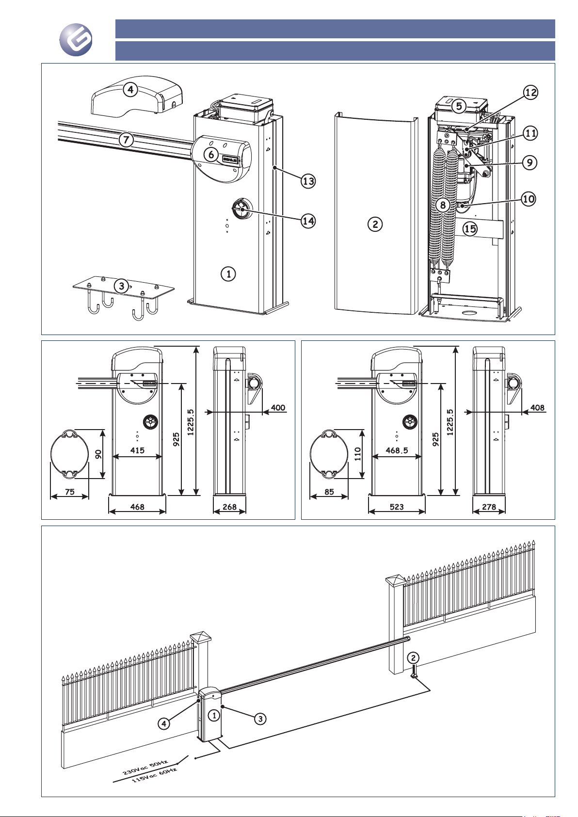
RAINBOW 524 C- RAINBOW 724 C
Immagini - Images - Images - Imágenes - Bilder - Afbeeldingen
Pag. 1
Fig. 1
Fig. 2 Fig. 3
Fig. 4
Page 20

RAINBOW 524 C - RAINBOW 724 C
Immagini - Images - Images - Imágenes - Bilder - Afbeeldingen
Pag. 2
Fig. 5 Fig. 6
Fig. 7 Fig. 8
Fig. 9
Fig. 10
Fig. 11
Page 21

RAINBOW 524 C- RAINBOW 724 C
Immagini - Images - Images - Imágenes - Bilder - Afbeeldingen
Pag. 3
Fig. 18 Fig. 19
Fig. 16 Fig. 17
Fig. 14 Fig. 15
Fig. 12 Fig. 13
Page 22

RAINBOW 524 C - RAINBOW 724 C
Immagini - Images - Images - Imágenes - Bilder - Afbeeldingen
Pag. 4
Fig. 20 Fig. 21
Fig. 22 Fig. 23
Fig. 24
Fig. 25 Fig. 26
Page 23

RAINBOW 524 C
RAINBOW 724 C
IstRuzIONI peR l’usO - INstRuCtIONs fOR use
INstRuCtIONs pOuR l’usAGeR - INstRuCCIONes pARA el usO
GeBRAuChsANleItuNG - GIds vOOR de GeBRuIkeR
Page 24

RAINBOW 524 C - RAINBOW 724 C
ITALIANO
Istruzioni per l’uso
Pagina 2
Prima di utilizzare il prodotto leggere attentamente le istruzio-
ni.
Conservare le presenti istruzioni per riferimenti futuri.
Vi ringraziamo per aver scelto un nostro prodotto. GENIUS è certa
che da esso otterrete tutte le prestazioni necessarie al Vostro impiego. Tutti i nostri prodotti sono frutto di una pluriennale esperienza
nel campo degli automatismi, rafforzata dal fatto di essere parte
del gruppo leader mondiale del settore.
Le automazioni della famiglia RAINBOW sono barrire elettromeccaniche progettate e realizzate per il controllo di accessi veicolari.
Durante la fase di progettazione è stata prestata particolare
attenzione alle più svariate esigenze d’installazione, è nato così
un prodotto attento all’ergonomina dell’installatore, la centrale è
posizionata nella parte superiore dell’automazione e può essere
ruotata, ed alla facilità d’installazione, sul cofano sono presenti
le predisposizione per l’alloggiamento delle fotocellule e del
selettore a chiave. Inoltre sia sul cofano che sulle sbarre vi è la
possibilità di installare dei cordoni luminosi, sostituendo il classico
lampeggiante.
Grazie alle varie tipologie di aste disponibili possono essere utilizzate
nei più svariati tipi di accessi, da un minimo di 3 metri sino ad un
massimo di 7 metri, nel caso di applicazioni singole.
Queste automazioni sono caratterizzate da una struttura in acciaio
con verniciatura a polvere che racchiude un motoriduttore elettromeccanico irreversibile.
Un comodo dispositivo di sblocco, protetto con chiave personalizzata, permette di movimentare manualmente l’asta in caso di
mancanza di alimentazione.
Grazie all’utilizzo di motori a 24V ed all’encoder, fornito di serie,
tutte le automazioni della famiglia RAINBOW offrono elevate
garanzie di sicurezza. Inoltre, se correttamente installate, possono
permettere di realizzare delle installazioni conformi alle vigenti
norme di sicurezza.
NORME GENERALI DI SICUREZZA
L’automazione RAINBOW, se correttamente installata ed utilizzata, garantisce un elevato grado si sicurezza. Alcune semplici
norme di comportamento possono inoltre evitare inconvenienti
accidentali:
Non transitare con l’asta in movimento. Prima di transitare attendere la completa apertura della sbarra.
Non sostare assolutamente sotto l’asta.
Tenere fuori dalla portata dei bambini i radiocomandi o qualsiasi
altro datore d’impulso per evitare che l’automazione possa essere
messa in funzione accidentalmente.
Non permettere ai bambini di giocare con l’automazione.
Non contrastare volontariamente il movimento dell’asta.
Evitare che rami o arbusti possano interferire con il movimento
dell’asta.
Mantenere efficienti e ben visibili i sistemi di segnalazione visiva.
Non tentare di movimentare manualmente l’asta se non dopo
averla sbloccata.
In caso di malfunzionamento togliere tensione, sbloccare l’asta
per consentire l’accesso ed attendere l’intervento di personale
qualificato.
Una volta predisposto il funzionamento manuale, prima di ripristinare il normale funzionamento, assicurarsi che l’impianto non
sia alimentato.
Non eseguire alcuna modifica ai componenti facenti parte
dell’automazione.
Far verificare, con cadenza semestrale, il corretto funzionamento
dell’automazione.
Astenersi da qualsiasi tentativo di riparazione o d’intervento e
rivolgersi solo ed esclusivamente a personale qualificato GENIUS
o ai centri di assistenza GENIUS.
Verificare che il tecnico installatore compili il registro di manutenzione allegato
FUNZIONAMENTO MANUALE
Nel caso si renda necessario movimentare manualmente l’asta
a causa di disservizio dell’automazione o mancanza della rete
elettrica agire come di seguito:
Togliere tensione all’impianto agendo sull’interruttore differen-
ziale a monte dell’impianto.
Inserire la chiave nel dispositivo di sblocco e ruotarla in senso
orario sino al suo arresto, come indicato in fig. 1 rif. a.
Ruotare il dispositivo di sblocco in senso orario sino al suo arresto,
•
•
•
•
•
•
•
•
•
•
•
•
•
•
•
•
fig. 1 rif. b.
Muovere manualmente l’asta, fig. 1 rif. c.
Fig. 1
RIPRISTINO DEL FUNZIONAMENTO NORMALE
Per evitare che un impulso involontario possa mettere in
funzione l’automazione, prima di ripristinare il normale funzionamento assicurarsi che l’impianto non sia alimentato
agendo sull’interruttore differenziale.
Ruotare il dispositivo di sblocco in senso antiorario sino al suo
arresto, Fig. 2 rif. a.
Ruotare la chiave in senso antiorario sino al suo arresto ed estrarla,
fig. 2 rif b.
Muovere manualmente l’asta sino al suo arresto, fig. 2 rif. c.
Ripristinare tensione all’impianto.
Fig. 2
MANUTENZIONE
Al fine di assicurare nel tempo un corretto funzionamento ed un
costante livello di sicurezza eseguire, con cadenza semestrale, un
controllo generale dell’impianto prestando particolare attenzione
ai dispositivi di sicurezza. Nel fascicolo “Istruzioni per l’uso” è stato
predisposto un modulo per la registrazione degli interventi.
Tutte le operazioni di manutenzione devono essere eseguite
da personale qualificato GENIUS o da centri d’assistenza
GENIUS.
RIPARAZIONI
L’utente utilizzatore deve astenersi da qualsiasi tentativo di riparazione o d’intervento e deve rivolgersi solo ed esclusivamente a
personale qualificato GENIUS o centri d’assistenza GENIUS.
•
•
•
•
•
Page 25
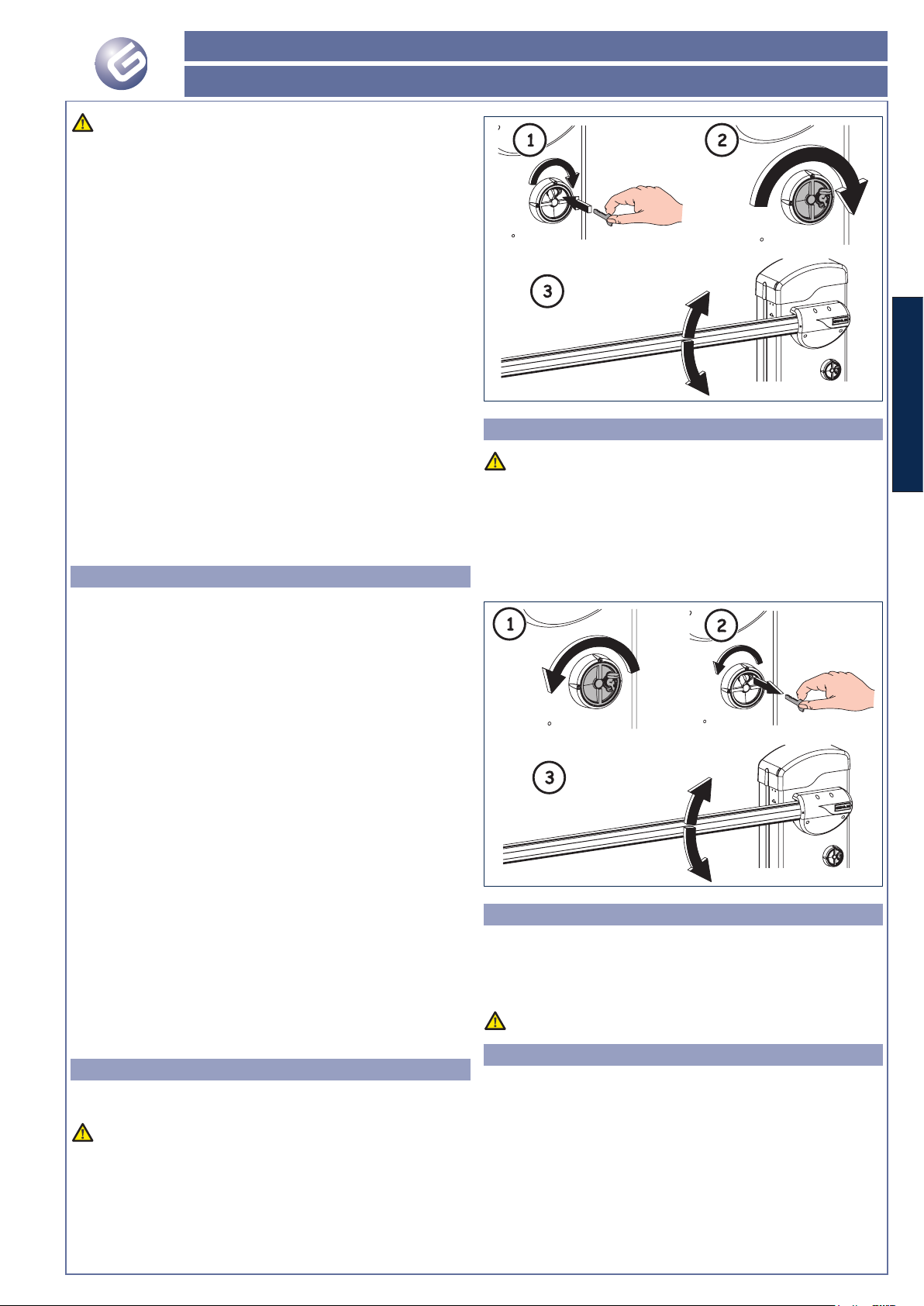
RAINBOW 524 C- RAINBOW 724 C
ENGLISH
Instructions for use
Page 3
Carefully read the instructions before using the product.
Store these instructions for future reference.
Thank you for choosing our product. GENIUS is sure you will get the
performances you expect to satisfy your requirements.
All our products are the result of a many years’ experience in the
field of the automated systems, strengthened by being part of a
world leading group in this sector.
The automated systems of the RAINBOW family are electromechanical barriers which have been designed and realised to
control vehicle accesses.
During design particular attention has been paid to the many
installation requirements. The result has been a product attentive
to installer ergonomy, the control unit is located on the upper
part of the automated system and can be rotated. Attention has
also been paid to the ease of installation: suitable facilities for the
photocells and the key-selector are present on the housing. Both
on the housing and on the rods you can install luminous strips,
replacing thus the traditional flashing lamp.
Thanks to the various types of rods available, these can be used in
very different types of accesses, from a minimum of 3 meters to a
maximum of 7 meters in case of single applications.
These automated systems consist of a steel structure with
powder paint enclosing the non-reversing electro-mechanical
gearmotor.
A handy release device, protected by customised key, enables you
to move the rod by hand in the event of a power cut.
Thanks to the use of 24V motors and of the encoder (standard
supplied), all automated systems of the RAINBOW family are able to
guarantee very high safety levels. If correctly installed, they realise
installations in compliance with current safety standards.
GENERAL SAFETY REGULATIONS
If correctly installed and used, the RAINBOW automated system
guarantees a high level of safety. Certain simple rules of behaviour
can also avoid accidental hitches:
Do not transit when the rod is moving. Transit is only allowed when
the beam is completely open.
Do not in any way stand under the rod.
Keep radio controls or any other pulse generators out of reach of
children, to prevent the automated system from being activated
involuntarily.
Do not allow children to play with the automated system.
Do not willingly impede the movement of the rod.
Prevent any branches or shrubs from interfering with the
movement of the rod.
Keep the signalling systems clearly visible and operating
efficiently.
Do not attempt to manually move the rod unless you have
released it.
In the event of malfunctions, cut power, release the rod to permit
access and wait for qualified personnel to do the necessary
work.
Once the system has been set in manual mode, before restoring
normal operation check that the system is not powered.
Do not make any modifications to the components of the
automated system.
Have the efficiency of the automated system checked every
six months.
Do not attempt any kind of repair or direct action whatsoever;
these operations must only be carried out by GENIUS qualified
personnel or by GENIUS service centres.
Make sure that the installing technician fills out the enclosed
maintenance register
MANUAL OPERATION
If a manual operation of the rod is necessary due to a fault of the
automated system or to a power cut, operate as follows:
Cut power to the system using the differential switch upstream
of the system.
Insert the key into the release device and turn it clockwise until it
stops, as shown in fig. 1 ref. a.
Turn the release device clockwise until it stops, fig. 1 ref. b.
Move the rod by hand, fig. 1 ref. c.
•
•
•
•
•
•
•
•
•
•
•
•
•
•
•
•
•
Fig. 1
RESTORING NORMAL OPERATION
To prevent an involuntary pulse from activating the automated
system, make sure the system is not powered up using
the differential switch, before restoring normal operation
mode.
Turn the release device counter-clockwise until it stops, Fig. 2
ref. a.
Turn the key counter-clockwise until it stops and then remove it,counter-clockwise until it stops and then remove it,clockwise until it stops and then remove it,
fig. 2 ref b.
Move the rod by hand until it stops, fig. 2 ref. c.
Power up the system.
Fig. 2
MAINTENANCE
To ensure a correct operation and a constant safety level over time
perform, every six months, a general check of the system paying
special attention to the safety devices. The booklet “Instructions
for use” contains a form for the registration of the maintenance
operations.
Every maintenance job must be performed by GENIUS qualified
personnel or by GENIUS service centres.
REPAIRS
The user must not attempt any repair or job and must only and
exclusively contact qualified GENIUS personnel or GENIUS service
centres.
•
•
•
•
Page 26

RAINBOW 524 C - RAINBOW 724 C
FRANÇAIS
Instructions pour l’usager
Page 4
Lire attentivement les instructions avant d’utiliser le produit.
Conserver ces instructions pour toute référence future.
Nous vous remercions d’avoir choisi un de nos produits. GENIUS est
certaine qu’il vous permettra d’obtenir toutes les performances
nécessaires pour votre usage.
Tous nos produits sont le fruit d’une longue expérience dans le
domaine des automatismes, renforcée par le fait que la société
appartient au groupe leader mondial du secteur.
Les automatismes de la famille RAINBOW sont des barrières
électromécaniques conçues et réalisées pour le contrôle des
accès de véhicules.
Durant la phase de conception, on a tenu compte des exigences
d’installation les plus disparates ; c’est ainsi qu’est né un produit
attentif à l’ergonomie de l’installateur (la centrale est positionnée
dans la partie supérieure de l’automatisme et on peut la faire
pivoter) ainsi qu’à la facilité d’installation (le capot est disposé pour
le logement des photocellules et du sélecteur à clé). En outre, on
peut installer sur le capot et sur les lisses des cordons lumineux à la
place de la lampe clignotante classique.
On peut utiliser les différents types de lisses disponibles sur de
nombreux types d’accès, d’un minimum de 3 mètres à un maximum
de 7 mètres, en cas d’applications individuelles.
Ces automatismes sont caractérisés par une structure en acier
peinte à la poudre, contenant un motoréducteur électromécanique
irréversible.
Un dispositif pratique de déverrouillage, protégé par une clé
personnalisée, permet d’actionner manuellement la lisse en cas
de coupure de courant.
Grâce aux moteurs 24V et à l’encodeur, fourni en série, tous
les automatismes de la famille RAINBOW offrent d’importantes
garanties de sécurité. S’ils sont correctement installés, ils permettent
de rèaliser des installations conformes aux règles de sécurité en
vigueur.
PRESCRIPTIONS GÉNÉRALES DE SÉCURITÉ
Si l’automatisme RAINBOW est correctement installé et utilisé, il
garantit un haut niveau de sécurité. Par ailleurs, quelques règles
simples de comportement peuvent éviter bien des accidents:
Ne pas transiter sous la lisse en mouvement. Avant de transiter,
attendre l’ouverture complète de la lisse.
Ne jamais stationner sous la lisse.
Éloigner de la portée des enfants les radiocommandes ou tout
autre dispositif générateur d’impulsion, pour éviter l’actionnement
involontaire de l’automatisme.
Interdire aux enfants de jouer avec l’automatisme.
Ne pas contraster volontairement le mouvement de la lisse.
Éviter que des branches ou des arbustes n’entravent le
mouvement de la lisse.
Faire en sorte que les systèmes de signalisation visuelle soient
toujours efficients et bien visibles.
N’act i onner manu e lleme n t la liss e qu’a p rès l ’ av o i r
déverrouillée.
En cas de dysfonctionnement, mettre hors tension, déverrouiller
la lisse pour permettre l’accès et attendre l’intervention du
personnel qualifié.
Lorsque le fonctionnement manuel a été disposé, mettre
l’installation hors tension avant de rétablir le fonctionnement
normal.
N’effectuer aucune modification sur les composants qui font
partie de l’automatisme.
Faire vérifier, au moins tous les six mois, le fonctionnement de
l’automatisme.
Éviter toute tentative de réparation ou d’intervention et s’adresser
uniquement au personnel qualifié GENIUS ou aux centres
d’assistance GENIUS.
Vérifier que l’installateur remplisse bien le registre d’entretien
annexé
FONCTIONNEMENT MANUEL
S’il est nécessaire d’actionner manuellement la lisse suite à un
dysfonctionnement de l’automatisme ou à une coupure de
courant, procéder comme suit :
Mettre l’installation hors tension en agissant sur le disjoncteur
différentiel en amont de l’installation.
Introduire la clé dans le dispositif de déverrouillage et la tourner
en sens horaire jusqu’à son arrêt, d’après la Fig. 1 réf. a.
Tourner le dispositif de déverrouillage en sens horaire jusqu’à son
•
•
•
•
•
•
•
•
•
•
•
•
•
•
•
•
arrêt, fig. 1 réf. b
Actionner manuellement la lisse, Fig. 1 réf. c.
Fig. 1
RÉTABLISSEMENT DU FONCTIONNEMENT NORMAL
Pour éviter qu’u ne impul sion involonta ire n’a ctionn e
l’automatisme, avant de rétablir son fonctionnement normal,
mettre l’installation hors tension en agissant sur le disjoncteur
différentiel.
Tourner le dispositif de déverrouillage en sens inverse horaire
jusqu’à son arrêt, fig. 2 réf. a.
Tourner la clé en sens inverse horaire jusqu’à l’arrêt et l’extraire,
fig. 2 réf. b.
Actionner manuellement la lisse jusqu’à l’arrêt, Fig. 2 réf. c.
Remettre l’installation sous tension.
Fig. 2
ENTRETIEN
Afin d’assurer dans le temps un fonctionnement correct et un
niveau de sécurité constant, exécuter, tous les semestres, un
contrôle général de l’installation, en faisant particulièrement
attention aux dispositifs de sécurité. Dans le livret « Instructions
pour l’Utilisateur », on a disposé un formulaire d’enregistrement
des interventions.
Toutes les opérations d’entretien doivent être effectuées par
du personnel qualifié GENIUS ou par les centres d’assistance
GENIUS.
RÉPARATIONS
L’utilisateur doit s’abstenir de toute tentative de réparation ou
d’intervention et doit s’adresser uniquement et exclusivement à du
personnel qualifié GENIUS ou aux centres d’assistance GENIUS.
•
•
•
•
•
Page 27

RAINBOW 524 C- RAINBOW 724 C
ESPAÑOL
Instrucciones para el uso
Página 5
Antes de utilizar el pro ducto lea detenidamente la s
instrucciones.
Conserve las presentes instrucciones para futuras consultas.
Les agradecemos que hayan elegido un producto GENIUS. GENIUS
tiene la certeza de que nuestro producto le brindará todas las
prestaciones que necesita.
Todos nuestros productos son fruto de una amplia experiencia en el
campo de los automatismos, experiencia que se ha visto reforzada
al formar parte del grupo líder mundial del sector.
Los automatismos de la fa mi l i a RAINBOW son barre r a s
electromecánicas diseñadas y realizadas para el control de
accesos de vehículos.
Durante la fase de diseño se ha prestado una especial atención
a las exigencias de instalación, a fin de obtener un producto
atento tanto a la ergonomía de instalación -la central está situada
en la parte superior del automatismo y puede girarse- como a
la facilidad de instalación -el cárter ya está preparado para el
alojamiento de las fotocélulas y del selector de llave-. Además,
tanto en el cárter como en las barras se pueden instalar unos
cordones luminosos en sustitución del clásico destellador.
Gracias a los distintos tipos de barras disponibles se pueden utilizar
en los más variados tipos de accesos, de un mínimo de 3 metros a
un máximo de 7 metros en caso de aplicaciones simples.
Estos automatismos se caracterizan por su estructura de acero con
pintura al polvo que contiene un motorreductor electromecánico
irreversible.
Un cómodo dispositivo de desbloqueo, protegido con llave
personalizada, permite mover manualmente la barra en caso de
falta de alimentación eléctrica.
Gracias al uso de motores de 24V y al encoder, suministrado de
serie, todos los automatismos de la familia RAINBOW ofrecen
elevadas garantías de seguridad. Además, si se instalan
correctamente, garantizan una instalación conforme con las
normas de seguridad.
NORMAS GENERALES DE SEGURIDAD
El automatismo RAINBOW, si se instala y utiliza correctamente,
garantiza un elevado grado de seguridad. Algunas simples
normas de comportamiento pueden evitar inconvenientes o
accidentes:
No transite con la barra en movimiento. Antes de transitar, espere
a que la barra se haya abierto completamente.
Por ningún motivo se detenga debajo de la barra.
Mantenga fuera del alcance de los niños radiomandos o cualquier
otro generador de impulsos para evitar que el automatismo
pueda ponerse en funcionamiento involuntariamente.
No permita que los niños jueguen con el automatismo.
No obstaculice voluntariamente el movimiento de la barra.
Evite que ramas o arbustos interfieran con el movimiento de la
barra.
Mantenga en buen estado y bien visibles los sistemas de
señalización visiva.
No i n tente mover manu a lment e la b arra s i no e stá
desbloqueada.
En caso de mal funcionamiento, quite la tensión, desbloquee la
barra para permitir el acceso y espere a que personal técnico
cualificado intervenga para solucionar el problema.
Una vez preparado el funcionamiento manual, quite la
alimentación eléctrica al equipo antes de reanudar el
funcionamiento normal.
No efectúe ninguna modificación en los componentes que
formen parte del automatismo.
Haga verificar, con periodicidad semestral, que el automatismo
funcione correctamente.
El usuario debe abstenerse de intentar reparar o de intervenir
directamente, y debe dirigirse exclusivamente a personal
cualificado GENIUS o a centros de asistencia GENIUS.
Compruebe que el técnico instalador cumplimente el registro
de mantenimiento adjunto
FUNCIONAMIENTO MANUAL
Si fuera necesario mover manualmente la barra en caso de
avería o de falta de alimentación eléctrica proceda del siguiente
modo:
Quite la tensión al equipo por medio del interruptor diferencial
situado línea arriba del equipo.
Introduzca la llave en el dispositivo de desbloqueo y gírela en
•
•
•
•
•
•
•
•
•
•
•
•
•
•
•
sentido horario hasta el tope, como se indica en la fig. 1 ref. a.
Gire el dispositivo de desbloqueo en sentido horario hasta su
tope, fig. 1 ref. b.
Mueva manualmente la barra, fig. 1 ref. c.
Fig. 1
RESTABLECIMIENTO DEL FUNCIONAMIENTO
NORMAL
Para evitar que un impulso involuntario pueda accionar el
automatismo, antes de restablecer el funcionamiento
normal asegúrese, por medio del interruptor diferencial, de
que el equipo no esté alimentado.
Gire el dispositivo de desbloqueo en sentido antihorario hasta
su tope, fig. 2 ref. a.
Gire la llave en sentido antihorario hasta su tope y quítela, fig.
2 ref. b.
Mueva manualmente la barra hasta su tope, fig. 2 ref. c.
Restablezca la tensión al equipo.
Fig. 2
MANTENIMIENTO
Para asegurar un correcto funcionamiento a lo largo del tiempo
y un constante nivel de seguridad es conveniente realizar, con
periodicidad semestral, un control general del equipo y prestar
especial atención a los dispositivos de seguridad. En el fascículo
“Instrucciones de uso” se ha preparado un módulo para anotar
las intervenciones.
Todas las operaciones de mantenimiento deben ser realizadas
por personal cualificado GENIUS o por centros de asistencia
GENIUS.
REPARACIONES
El usuario debe abstenerse de intentar reparar o de intervenir
directamente, y debe dirigirse exclusivamente a personal
cualificado GENIUS o a centros de asistencia GENIUS.
•
•
•
•
•
•
Page 28

RAINBOW 524 C - RAINBOW 724 C
DEUTSCH
Gebrauchsanleitung
Page 6
Vor der Verwendung des Produkts ist die Betriebsanleitung
aufmerksam zu lesen.
Di e s e A n w e is un ge n f ü r d i e zu k ü n ftige Kons u l t a ti o n
aufbewahren.
Wir danken Ihnen für den Kauf unseres Produkts. GENIUS ist sicher,
dass dieses Produkt Ihnen alle für Ihren Einsatz erforderlichen
Leistungen zur Verfügung stellt.
Unsere Produkte sind das Ergebnis unserer mehrjährigen Erfahrung
im Bereich Automationssysteme, die dadurch verstärkt wird, dass
wir zum weltweit führenden Konzern in dieser Branche gehören.
Bei den Automationen der Produktfamilie RAINBOW handelt es sich
um elektromechanische Schranken für die Zufahrtskontrolle.
Bei der Konstruktion wurden die verschiedenen Montagebedürfnisse
besonders berücksichtigt. Das Ergebnis ist daher ein Produkt, bei
dem Wert auf die Körperhaltung des Monteurs gelegt wird.
Das Steuergerät befindet sich im oberen Teil der Automation
und kann gedreht werden. Zur einfacheren Montage sind am
Gehäuse Aufnahmen für die Fotozellen und den Schlüsselschalter
ausgebildet. Außerdem können sowohl am Gehäuse als auch
an den Balken Lichterketten anstelle der klassischen Blinkleuchte
montiert werden.
Dank der verschiedenen verfügbaren Stangentypen können die
Schranken für die verschiedensten Zugangssysteme mit einer Breite
von mindestens 3 m und maximal 7 m (bei Einzelanwendungen)
verwendet werden.
Diese Automationen zeichnen sich durch eine pulverbeschichtete
Stahlkonstruktion aus, die ein irreversibles elektromechanisches
Getriebe umfasst.
Ein praktisches manuelles Entriegelungssystem mit ID-Schlüssel
ermöglicht die Bewegung der Stange bei Stromausfall.
Dank der Verwendung von 24-V-Motoren und Encoder (im
Standardlieferumfang enthalten) bieten alle Automationen
der Produktfamilie RAINBOW hohe Sicherheitsgarantien. Bei
sachgemäßem Einbau sind Installationen gemäß den geltenden
Sicherheitsvorschriften möglich.
ALLGEMEINE SICHERHEITSVORSCHRIFTEN
Be i korrek ter Installation und sachgem äßer Anwendung
gewährleistet die Automation RAINBOW ein hohes Sicherheitsniveau.
Einige einfache Verhaltensregeln können außerdem ungewollte
Störungen vermeiden:
Während sich die Stange bewegt, nicht durchfahren/durchgehen.
Vor der Durchfahrt/dem Durchgang die vollständige Öffnung des
Balkens abwarten.
Personen dürfen sich auf keinen Fall unter der Stange aufhalten.
Funksteuerungen oder andere Impulsgeber sind außerhalb der
Reichweite von Kindern aufzubewahren, um zu vermeiden, dass
die Automation ungewollt betätigt wird.
Kinder dürfen nicht mit der Automation spielen.
Die Bewegung der Stange darf nicht absichtlich behindert
werden.
Vermeiden, dass Zweige oder Büsche die Bewegung der Stange
beeinträchtigen.
Darauf achten, dass die Leuchtsignalsysteme stets funktionstüchtig
und gut sichtbar sind.
Die Stange darf nur dann mit der Hand betätigt werden, wenn
sie entriegelt wurde.
Bei Betriebsstörungen die Spannungszufuhr unterbrechen,
die Stange entriegeln, um den Zugang zu ermöglichen und
technische Fachkräfte benachrichtigen.
Wenn der Handbetrieb eingestellt ist, muss vor der Wiederherstellung
des Normalbetriebs die Stromzufuhr zur Anlage unterbrochen
werden.
Keine Änderungen an den Bauteilen des Automationssystems
vornehmen.
Alle sechs Monate den einwandfreien Betrieb der Automation
prüfen lassen.
Der Benutzer darf direkt keine Versuche für Reparaturen oder
Arbeiten vornehmen und hat sich ausschließlich an qualifiziertes
GENIUS-Fachpersonal oder an GENIUS-Kundendienstzentren zu
wenden.
Sicherstellen, dass der Monteur das beiliegende Wartungsregister
ausfüllt
MANUELLER BETRIEB
Sollte es aufgrund von Stromausfall oder Betriebsstörungen der
Automation erforderlich sein, die Stange manuell zu bewegen, sind
•
•
•
•
•
•
•
•
•
•
•
•
•
•
folgende Schritte auszuführen:
Mi t hi l f e d e s d e r A n l a g e v o r g e s c h a l t e t e n
Fehlerstromschutzschalters die Stromzufuhr zur Anlage
unterbrechen.
Den Schlüssel in die Entriegelungsvorrichtung einsetzen und bis
zum Anschlag im Uhrzeigersinn drehen, siehe Angaben in Abb.
1, Bez. a.
Die Entriegelungsvorrichtung im Uhrzeigersinn bis zum Anschlag
drehen, siehe Abb. 1, Bez. b.
Die Stange manuell bewegen, siehe Abb. 1, Bez c.
Fig. 1
WIEDERHERSTELLUNG DES NORMALBETRIEBS
Um zu vermeiden, dass ein unbeabsichtigter Impuls die Automation
in Betrieb setzt, vor der Wiederherstellung des Normalbetriebs
mithilfe des Fehlerstromschutzschalters sicherstellen, dass die
Stromzufuhr zur Anlage unterbrochen ist.
Die Entriegelungsvorrichtung gegen den Uhrzeigersinn bis zum
Anschlag drehen, siehe Abb. 2, Bez. a.
Den Schlüssel bis zum Anschlag gegen den Uhrzeigersinn drehen
und abziehen, siehe Abb. 2 Bez. b.
Die Stange von Hand bis zum Anschlag bewegen, siehe Abb.
2, Bez. c.
Die Anlage wieder mit Strom versorgen.
Fig. 2
WARTUNG
Zur Gewährleistung eines dauerhaft reibungslosen Betriebs und
eines konstanten Sicherheitsniveaus sollte im Abstand von jeweils
6 Monaten eine allgemeine Kontrolle der Anlage vorgenommen
werden, wobei besonders auf die Sicherheitseinrichtungen zu
achten ist. Im Heft „Betriebsanleitung“ ist ein Vordruck für die
Aufzeichnung der Wartungsarbeiten enthalten.
Alle Wartungsarbeiten müssen von GENIUS-Fachpersonal oder
GENIUS-Kundendienstzentren ausgeführt werden.
REPARATUREN
Der Benutzer darf direkt keine Versuche für Reparaturen oder
Arbeiten vornehmen und hat sich ausschließlich an GENIUSFachpersonal oder an GENIUS-Kundendienstzentren zu wenden.
•
•
•
•
•
•
•
Page 29

RAINBOW 524 C- RAINBOW 724 C
NEDERLANDS
Gids voor de gebruiker
Page 7
Lees alvorens het product te gebruiken aandachtig de
gebruiksaanwijzing door.
Bewaa r deze gebrui k s a a n w i j z i n g voor toekomstige
raadpleging.
Wij danken u dat u een product van ons heeft gekozen. GENIUS
weet zeker dat het alle prestaties zal verrichten die u nodig
heeft.
Al onze producten zijn het resultaat van vele jaren ervaring op het
gebied van automatische systemen, te meer daar wij marktleider
zijn in heel de wereld.
De au t o m a t i s c h e systemen van de serie RAINBOW zijn
elektromechanische slagbomen die zijn ontworpen en vervaardigd
voor toegangscontrole van voertuigen.
Tijdens de ontwerpfase is met name aandacht besteed aan
de meest uiteenlopende installatievereisten; zo is een product
ontstaan met oog voor de ergonomie van de installateur - de
besturingseenheid zit bovenin het automatisch systeem en kan
worden gedraaid - en het installatiegemak - de behuizing is
vooruitgerust om fotocellen en de sleutelschakelaar te kunnen
plaatsen. Daarnaast kunnen zowel op de behuizing als op de
boom lichtslangen worden geïnstalleerd, ter vervanging van de
traditionele waarschuwingslamp.
Dankzij de verschillende types armen die verkrijgbaar zijn, kunnen
ze voor de meest uiteenlopende soorten toegangen worden
gebruikt, van minimaal 3 meter tot maximaal 7 meter, als er één
slagboom wordt gebruikt.
De z e autom a tische sy stemen worden gekenme rkt door
een gepoederlakte stalen structuur die een onomkeerbare
elektromechanische motorreductor bevat.
Een handige ontgrendeling, beschermd met een eigen sleutel,
maakt het mogelijk de arm met te hand te bewegen voor het
geval de stroom uitvalt.
Doordat er standaard motoren van 24V en een encoder worden
gebruikt, bieden alle automatische systemen van de serie RAINBOW
een hoge mate van veiligheid. Bovendien kunnen met deze
systemen, als ze correct worden geïnstalleerd, installaties conform
de geldende veiligheidsvoorschriften worden vervaardigd.
ALGEMENE VEILIGHEIDSVOORSCHRIFTEN
Het automatisch systeem RAINBOW garandeert, als het op correcte
wijze is geïnstalleerd en gebruikt, een hoge mate van veiligheid.
Daarnaast kunnen een aantal simpele gedragsregels accidentele
ongemakken voorkomen:
Ga niet onder de arm door als hij in beweging is. Wacht tot de
arm helemaal open is alvorens er onderdoor te gaan.
Blijf nooit onder de arm staan.
Houd de radio-afstandsbediening en alle andere impulsgevers
buiten het bereik van kinderen, om te voorkomen dat het
automatisch systeem per ongeluk in werking wordt gezet.
Sta niet toe dat kinderen met het automatisch systeem spelen.
Houd niet opzettelijk de beweging van de arm tegen.
Zorg dat takken of struiken de beweging van de arm niet kunnen
hinderen.
Zorg dat de visuele signalen altijd goed werken en goed zichtbaar
zijn.
Probeer de arm niet met de hand te bewegen als hij niet eerst
ontgrendeld is.
In geval van storing moet de spanning worden uitgeschakeld en
de arm worden ontgrendeld om toegang mogelijk te maken, en
wacht dan op de assistentie van een gekwalificeerd technicus.
Als de handbediende werking is ingesteld, moet alvorens de
normale werking te herstellen worden gecontroleerd of de
elektrische voeding naar de installatie is uitgeschakeld.
Voer geen wijzigingen uit op onderdelen die deel uitmaken van
het automatisch systeem.
Laat ieder half jaar controleren of het automatisch systeem goed
werkt.
Doe zelf geen pogingen tot reparaties of andere ingrepen, en
wend u uitsluitend tot gekwalificeerd en erkend GENIUS-personeel
of een erkend GENIUS servicecentrum.
Controleer of de installerende technicus het bijgevoegde
onderhoudsregister invult
HANDBEDIENDE WERKING
Als de arm met de hand moet worden bewogen vanwege
een storing van het automatisch systeem of omdat de stroom is
uitgevallen, handel dan als volgt:
•
•
•
•
•
•
•
•
•
•
•
•
•
•
Schakel de spanning naar de installatie uit door op de
differentieelschakelaar stroomopwaarts van de installatie
te drukken.
Steek de sleutel in de ontgrendeling en draai hem met de wijzers
van de klok mee tot hij niet verder kan, zoals aangegeven in fig. 1 ref. a.
Draai de ontgrendeling met de wijzers van de klok mee tot zij niet
verder kan, fig. 1 ref. b.
Beweeg de arm met de hand, fig. 1 ref. c.
Fig. 1
HERSTEL NORMALE WERKING
Om te voorkomen dat het automatisch systeem tijdens de
manoeuvre per ongeluk door een impuls in werking wordt
gezet, moet alvorens de normale werking te hervatten de
voeding naar installatie wordt uitgeschakeld door op de
differentieelschakelaar te drukken.
Draai de ontgrendeling tegen de wijzers van de klok in tot zij niet
verder kan, Fig. 2 ref. a.
Draai de sleutel tegen de wijzers van de klok in tot hij niet verder
kan, en trek hem eruit (fig. 2 ref. b).
Beweeg de arm met de hand tot hij niet verder kan, fig. 2 ref. c.
Schakel de spanning naar installatie weer in.
Fig. 2
ONDERHOUD
Om een goede werking op de lange termijn en een constant
veiligheidsniveau te garanderen, moet ieder half jaar een algemene
controle op de installatie worden uitgevoerd, waarbij met name
de veiligheidsvoorzieningen goed moeten worden nagekeken.
Het boekje ‘Gebruiksaanwijzing’ bevat een voorgedrukt formulier
om ingrepen te registeren.
Alle onderhoudswerkzaamheden moeten door gekwalificeerd
en erkend personeel van GENIUS of een erkend GENIUSservicecentrum worden uitgevoerd.
REPARATIES
De gebruiker mag zelf geen pogingen ondernemen tot reparaties
of andere ingrepen, en dient zich uitsluitend te wenden tot
gekwalificeerd en geautoriseerd GENIUS-personeel of een erkend
GENIUS-servicecentrum.
•
•
•
•
•
•
•
Page 30

REGISTRO DI MANUTENZIONE / MAINTENANCE REGISTER / REGISTRE D’ENTTRETIEN / REGI-
STRO DE MANTENIMIENTO / WARTUNGSPROGRAMM / ONDERHOUDREGISTER
Dati impianto / System data / données de l’installation / Datos equipo / Daten der Anlage / Gegevens
installatie
Installatore / Installer / Installateur / Installador / Monteur / installateur
Cliente / Customer / Client / Cliente / Kunde / Klant
Tipo impianto / Type of system / Type d’installation / Tipo de equipo /
Art der Anlage / Type installatie
Matricola / Serial No. / N° de série / N° de serie / Seriennummer / Seriennummer
Data installazione / Installation date / Date d’installation / Fecha de
installatión / Installationsdatum / datum installatie
Attivazione / Start-up / Activation / Activación / Inbetriebnahme /
Activering
Configurazione impianto / System configuration / Confijguration de l’installation / Configuración del equi-
po / Konfiguration der Anlage / Configuratie installatie
COMPONENTE / PART / COMPOSANT / COMPONENTE
/ BAUTEIL / ONDEREEL
MODELLO / MODEL / MODÈLE / MODE-
LO / MEDELL / MODEL
MATRICOLA / SERIAL NUMBER / N° DE
SERIE / N° DE SERIE / SERIENNUMMER /
SERIENUMMER
Operatore / Operator / Opérateur / Operador / Antrieb
/ Aandrijving
Dispositivo di sicurezza 1 / Safety device 1 / dispositif
de sécurité 1 / Dispositivo de seguridad 1 / Scherheltsvorrichtung 1 / Velligheldsvoorziening 1
Dispositivo di sicurezza 2 / Safety device 2 / dispositif
de sécurité 2 / Dispositivo de seguridad 2 / Scherheltsvorrichtung 1 / Velligheldsvoorziening 2
Coppia di fotocellule 1 / Pair of photocells 1 / Paire de
photocellules 1 / Par de fotocélulas 1 / Fotozellenpaar
1 / Paar fotocellen 1
Coppia di fotocellule 2 / Pair of photocells 2 / Paire de
photocellules 2 / Par de fotocélulas 2 / Fotozellenpaar
2 / Paar fotocellen 2
Dispositivo di comando 1 / Control device 1 / Dispositif
de commande 1 / Dispositivi de mando 1 / Schaltvorrichtung 1 / Bedieningsvoorziening 1
Dispositivo di comando 2 / Control device 2 / Dispositif
de commande 2 / Dispositivi de mando 2 / Schaltvorrichtung 2 / Bedieningsvoorziening 2
Radiocomando / Radio control / Radiocommande /
Radiomando / Funksteuerung / Afstandsbediening
Lampeggiante / Flashing lamp / Lampe clignotante /
Destellador / Blinkleuchte / Signaallamp
Indicazione dei rischi residui e dell’uso improprio prevedibile / Indication of residual risks and of foreseeable improper use / Indi-
cation des risques résiduels et de l’usage impropre prévisible / Indicación de los riesgos residuos y del uso impropio previsible /
Angabe der Restrisiken und der voraussehbaren unsachgemäßen Anwendung / Aanduiding van de restrisico’s en van voorzienbaar
oneigenlijk gebruik
Registro di manutenzione - Maintenance register - Registre d’enttretien
Registro de mantenimeinto - Wartungsprogramm - Onderhoudregister
Page 31

Registro di manutenzione - Maintenance register - Registre d’enttretien
Registro de mantenimeinto - Wartungsprogramm - Onderhoudregister
Nr
Data / Date
/ Date /
Fecha /
Datum /
Datum
Descrizione intervento / Job description / Description de
l’intervention / Descripción de la intervención / Beschrei-
bung der Arbeiten / Beschrijving ingreep
Firme / Signatures / Signatures / Firma / Unterschrift /
Handtekeningen
1
Tecnico / Technicia
Technicien / Técnico
Techniker / Technicus
Cliente / Customer
Client / Cliente
Kunde / Klant
2
Tecnico / Technicia
Technicien / Técnico
Techniker / Technicus
Cliente / Customer
Client / Cliente
Kunde / Klant
3
Tecnico / Technicia
Technicien / Técnico
Techniker / Technicus
Cliente / Customer
Client / Cliente
Kunde / Klant
4
Tecnico / Technicia
Technicien / Técnico
Techniker / Technicus
Cliente / Customer
Client / Cliente
Kunde / Klant
5
Tecnico / Technicia
Technicien / Técnico
Techniker / Technicus
Cliente / Customer
Client / Cliente
Kunde / Klant
6
Tecnico / Technicia
Technicien / Técnico
Techniker / Technicus
Cliente / Customer
Client / Cliente
Kunde / Klant
7
Tecnico / Technicia
Technicien / Técnico
Techniker / Technicus
Cliente / Customer
Client / Cliente
Kunde / Klant
8
Tecnico / Technicia
Technicien / Técnico
Techniker / Technicus
Cliente / Customer
Client / Cliente
Kunde / Klant
9
Tecnico / Technicia
Technicien / Técnico
Techniker / Technicus
Cliente / Customer
Client / Cliente
Kunde / Klant
10
Tecnico / Technicia
Technicien / Técnico
Techniker / Technicus
Cliente / Customer
Client / Cliente
Kunde / Klant
Page 32

RAINBOW 524 C - RAINBOW 724 C
Note - Notes - Note - Notas - Anmerkung - Opmerkingen
Page 10
Page 33

RAINBOW 524 C- RAINBOW 724 C
Note - Notes - Note - Notas - Anmerkung - Opmerkingen
Page 11
Page 34

Le descrizioni e le illustrazioni del presente manuale non sono impegnative. GENIUS si riserva il diritto, lasciando inalterate le caratteristiche essenziali dell’apparecchiatura, di apportare in qualunque momento e senza impegnarsi ad aggiornare la presente pubblicazione, le modifiche che essa ritiene convenienti per miglioramenti tecnici o per qualsiasi altra esigenza di carattere costruttivo
o commerciale.
The descriptions and illustrations contained in the present manual are not binding. GENIUS reserves the right, whils leaving the main
features of the equipments unaltered, to undertake any modifications to holds necessary for either technical or commercial reasons,
at any time and without revising the present publication.
Les descriptions et les illustrations du présent manuel sont fournies à titre indicatif. GENIUS se réserve le droit d’apporter à tout moment
les modifications qu’elle jugera utiles sur ce produit tout en conservant les caractéristiques essentielles, sans devoir pour autant mettre
à jour cette publication .
Las descripciones y las ilustraciones de este manual no comportan compromiso alguno. GENIUS se reserva el derecho, dejando
inmutadas las características esenciales de los aparatos, de aportar, en cualquier momento y sin comprometerse a poner al día la
presente publicación, todas las modificaciones que considere oportunas para el perfeccionamiento técnico o para cualquier otro
tipo de exigencia de carácter constructivo o comercial.
Die Beschreibungen und Abbildungen in vorliegendem Handbuch sind unverbindlich. GENIUS behält sich das Recht vor, ohne die
wesentlichen Eigenschaften dieses Gerätes zu verändern und ohne Verbindlichkeiten in Bezung auf die Neufassung der vorliegenden
Anleitungen, technisch bzw, konstruktiv / kommerziell bedingte Verbesserungen vorzunehmen.
De beschrijvingen in deze handleiding zijn niet bindend. GENIUS behoudt zich het recht voor op elk willekeurig moment de veranderingen aan te brengen die het bedrijf nuttig acht met het oog op technische verbeteringen of alle mogelijke andere productie- of
commerciële eisen, waarbij de fundamentele eigenschappen van het apparaat gehandhaafd blijven, zonder zich daardoor te
verplichten deze publicatie bij te werken.
Timbro rivenditore: / Distributor’s stamp: / Timbre de l’agent: / Sello del revendedor: / Fachhändlerstempel: / Stempel dealer:
00058I0835 Rev.0
Via Padre Elzi, 32
24050 - Grassobbio
BERGAMO-ITALY
tel. 0039.035.4242511
fax. 0039.035.4242600
info@geniusg.com
www.geniusg.com
Page 35

RAINBOW 524 C- RAINBOW 724 C
Immagini - Images - Images - Imágenes - Bilder - Afbeeldingen
Pag. 5
Fig. 27
Fig. 28
Fig. 29
Page 36
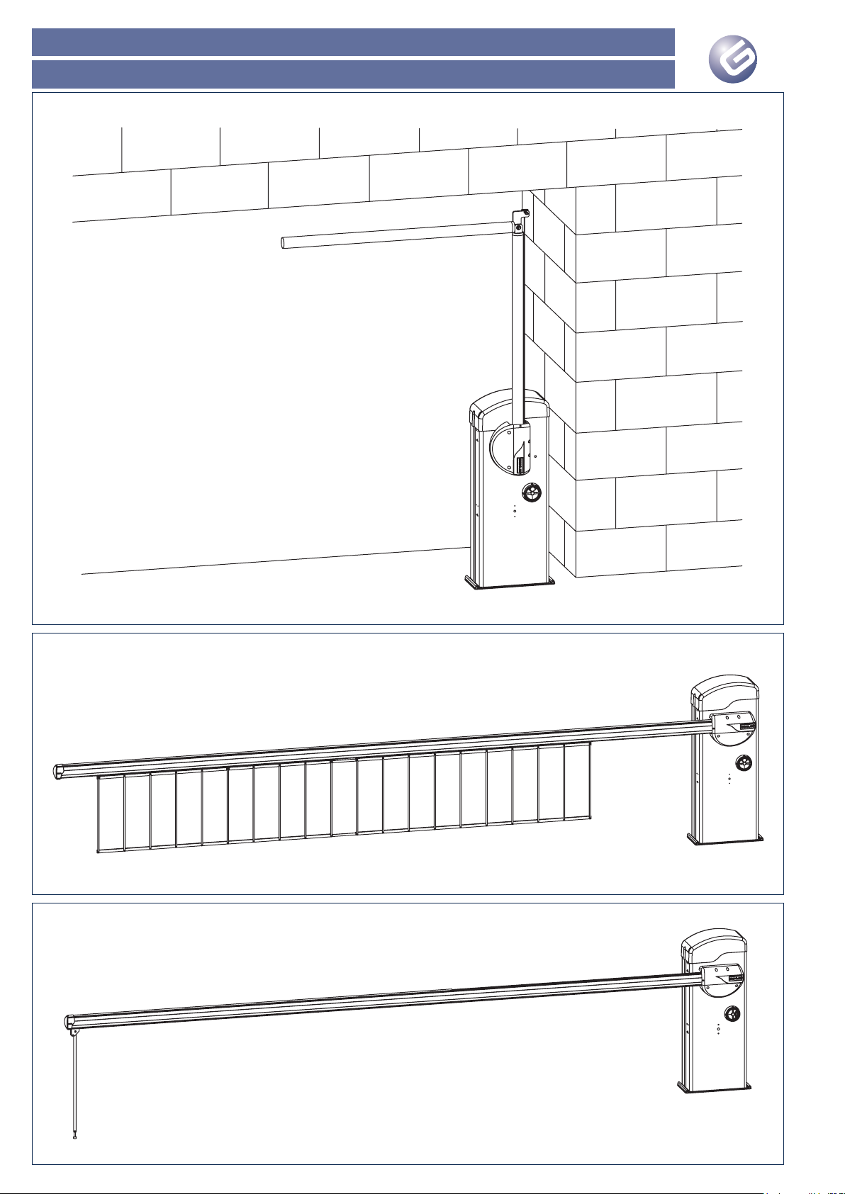
RAINBOW 524 C - RAINBOW 724 C
Immagini - Images - Images - Imágenes - Bilder - Afbeeldingen
Pag. 6
Fig. 30
Fig. 31
Fig. 32
Page 37

RAINBOW 524 C- RAINBOW 724 C
Immagini - Images - Images - Imágenes - Bilder - Afbeeldingen
Pag. 7
Fig. 33
Fig. 34
Page 38

RAINBOW 524 C - RAINBOW 724 C
Immagini - Images - Images - Imágenes - Bilder - Afbeeldingen
Pag. 8
Page 39

RAINBOW 524 C- RAINBOW 724 C
ESPAÑOL
Guía para el instalador
Página 17
Les agradecemos que hayan elegido un producto GENIUS.
GENIUS tiene la certeza de que nuestro producto le brindará todas
las prestaciones que necesita. Todos nuestros productos son fruto
de una amplia experiencia en el campo de los automatismos,
experiencia que se ha visto reforzada al formar parte del grupo
líder mundial del sector.
En el centro del manual se ha incluido un opúsculo separable
con todas las imágenes para la instalación.
Los automatismos de la fa mi l i a RAINBOW son barre r a s
electromecánicas diseñadas y realizadas para el control de
accesos de vehículos.
La central está situada en la parte superior del automatismo
y puede girarse para facilitar las operaciones de cableado y
configuración. En el cárter están presentes las predisposiciones
para el alojamiento de las fotocélulas (Orion) y del selector de
llave (Quick). Además, tanto en el cárter como en las barras se
pueden instalar unos cordones luminosos en sustitución del clásico
destellador.
Gracias a los distintos tipos de barras disponibles se pueden utilizar
en los más variados tipos de accesos, de un mínimo de 3 metros
a un máximo de 7 metros.
Un cómodo dispositivo de desbloqueo, protegido con llave
personalizada, permite mover manualmente la barra en caso de
falta de alimentación eléctrica.
Gracias al uso de motores de 24V y al encoder, suministrado de
serie, todos los automatismos de la familia RAINBOW ofrecen
elevadas garantías de seguridad.
NOTAS IMPORTANTES PARA EL INSTALADOR
Lea completamente el presente manual antes de empezar la
instalación.
Conserve el manual para futuras consultas.
El correcto funcionamiento y las características técnicas
declaradas sólo se obtienen respetando las indicaciones
presentes en este manual y con los accesorios y dispositivos de
seguridad GENIUS.
Si falta un dispositivo de embrague mecánico es necesario, a fin
de garantizar la seguridad del automatismo, utilizar una central de
mando con un dispositivo de embrague electrónico regulable.
El automatismo ha sido diseñado y fabricado para controlar el
acceso de vehículos. Evítese cualquier otro uso.
El operador no puede ser utilizado para mover salidas de
seguridad o cancelas instaladas en recorridos de emergencia
(vías de escape).
No transite con la barra en movimiento.
Todo aquello que no esté expresamente especificado en este
manual habrá de considerarse no permitido.
1. DESCRIPCIÓN
Con referencia a la figura 1:
Pos. Descripción
a
Montante
b
Portezuela
c
Placa de cimentación (vendida por separado)
d
Cárter
e
Contenedor central de mando
f
Cárter empalme barra
g
Barra (vendida por separado en función de las
exigencias de instalación)
h
Muelle de equilibrado (vendido por separado, número
y tipo en función del tipo de barra y de los accesorios
aplicados)
i
Motorreductor
j
Encoder
k
Final de carrera de cierre / apertura
l
Final de carrera de seguridad
m
Borde rojo (cobertura para cordón luminoso opcional)
n
Dispositivo de desbloqueo
o
Vano para baterías tampón (no suministradas)
•
•
•
•
•
•
•
•
1.1 CARACTERÍSTICAS TÉCNICAS
Modelo RAINBOW 524 C 724 C
Tensión de alimentación 230Vac 50Hz / 115Vac 60Hz
Tensión de alimentación motor
(Vdc)
24
Potencia máxima en arranque (W) 280 480
Potencia nominal motor (W) 160 220
Par máx. a 24Vdc (Nm) 140 370
Par nominal de funcionamiento
(Nm)
75 140
Tiempo nominal apertura / cierre
(seg)
a
da 4 a 8 da 7 a 11
Longitud máxima barra (m)
b
5 7
Tipo y frecuencia de utilización a
20°C
Semi-intensiva
Ciclos máximos diarios (ciclos) 1000 500
Te mp e r at u r a a m bi e n te de
funcionamiento (°C)
-20 +55
Nivel sonoro (dBA) <70
Grado de protección IP 54
Peso operador (Kg) 66 72
Dimensiones Véase fig. 2 Véase fig. 3 3
a Tiempo en función del tipo de deceleración programado.
b Longitud referida a la luz de paso, longitud barra +400mm
aprox
1.1.1. Vida del producto
En las siguientes tablas se indica la vida del producto, expresada
en número de ciclos, en función del tipo de barra elegida y de los
accesorios aplicados a la misma:
RAINBOW 524 C
Barra y accesorio Vida (N° ciclos)
3 metros 1.500.000
4 metros 1.300.000
5 metros 1.100.000
3 metros con pié terminal 1.300.000
4 metros con pié terminal 1.100.000
5 metros con pié terminal 800.000
3 metros con 2 metros de faldilla 1.300.000
4 metros con 3 metros de faldilla 1.100.000
5 metros con 4 metros de faldilla 800.000
RAINBOW 724 C
Barra y accesorio Vida (N° ciclos)
4 metros 1.300.000
5 metros 1.100.000
6 metros 850.000
7 metros 500.000
4 metros con pié terminal 1.100.000
5 metros con pié terminal 850.000
6.5 metros con pié terminal 500.000
4 metros con 2 metros de faldilla 1.100.000
5 metros con 3.5 metros de faldilla 850.000
6.5 metros con 5 metros de faldilla 500.000
La vida del producto ha sido calculada a una temperatura de
20°C con operadores instalados correctamente según las
especificaciones indicadas en las instrucciones.
Page 40
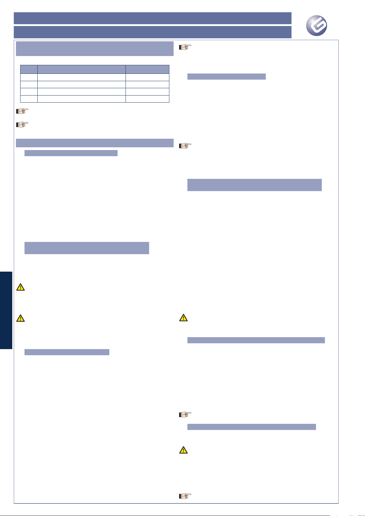
RAINBOW 524 C - RAINBOW 724 C
ESPAÑOL
Guía para el instalador
Página 18
2. PREDISPOSICIONES ELÉCTRICAS
(Equipo estándar)
Con referencia a la figura 4:
Pos. Descripción Sección cables
a
Operador (alimentación eléctrica) 3x1.5 mm
2
b
Fotocélula TX 2x0.5 mm
2
c
Fotocélula RX 4x0.5 mm
2
d
Selector de llave 2x0.5 mm
2
Para tender los cables eléctricos, utilice tubos rígidos y/o
flexibles adecuados
No dejar que los cables de conexión de los accesorios a
baja tensión se toquen con los de la alimentación. Para
evitar posibles interferencias utilice vainas separadas.
3. INSTALACIÓN DEL AUTOMATISMO
3.1. COMPROBACIONES PREVIAS
Para garantizar la seguridad y para un correcto funcionamiento
del automatismo, compruebe que se verifiquen los siguientes
requisitos:
La barra, durante su movimiento, no debe encontrar ningún
obstáculo o cables eléctricos aéreos.
Las características del terreno deben garantizar una suficiente
estabilidad de la base de cimentación.
En la zona de excavación de la base de cimentación no deben
haber tuberías o cables eléctricos.
Si el cuerpo de la barrera se encuentra expuesto al paso
de vehículos, deben preverse, si fuera posible, adecuadas
protecciones contra golpes accidentales.
Compruebe la existencia de una eficiente toma de tierra para
la conexión del montante.
3.2. COLOCACIÓN EN OBRA DE LA PLACA DE
CIMENTACIÓN
Ensamble la placa de cimentación tal y como se indica en la
figura 5.
Realice una base de cimentación tal y como se indica en la
figura 6.
Las dimensiones de la base han de ser adecuadas al tipo de
instalación y al tipo de terreno.
Coloque en obra la placa de cimentación como se indica en
la figura 6, y prevea una o varias vainas para el paso de los
cables eléctricos.
La parte abombada de la placa de cimentación ha de
estar orientada hacia el interior del paso que se ha de
automatizar.
Compruebe la perfecta horizontalidad de la placa con un
nivel.
Espere a que fragüe el cemento.
3.3. INSTALACIÓN MECÁNICA
Retire las 4 tuercas superiores de la placa de cimentación.
Destornille los dos tornillos de fijación del cárter superior, véase
Fig.7, ref. a.
Introduzca la llave de desbloqueo en la cerradura del cárter,
Fig. 8, y gírela en sentido horario hasta el tope.
Manteniendo la llave en esta posición, retire el cárter superior,
Fig. 8.
Retire la portezuela como se indica en la fig. 9.
Coloque el montante sobre los cuatro tirantes roscados como
se indica en la fig. 10 y apriete las cuatro tuercas de fijación.
Prepare el automatismo para el funcionamiento manual, véase
párrafo 7.
Coloque la barra porta-muelle, Fig. 11 ref. a, en posición
horizontal.
Fije el plato porta-muelle como se indica en la figura 12, en
función del tipo de cierre:
si la barra desciende a la izquierda del montante, instalación
derecha, el plato debe fijarse en el perno b de la figura 11.
si la barra desciende a la derecha del montante, instalación
izquierda, el plato debe fijarse en el perno c de la figura 11.
Gire el plato porta-muelle en la posición indicada en la fig. 13,
en función del tipo de instalación, Der. o Izq.
En la parte delantera del automatismo coloque el plato portabarra y manténgalo en posición horizontal, Fig. 14.
•
•
•
•
•
1.
2.
3.
4.
5.
1.
2.
3.
4.
5.
6.
7.
8.
9.
•
•
10.
11.
Para el modelo RAINBOW 724 C preste atención a la
orientación de los orificios marcados en la Fig. 14, ref. a,
los orificios deben estar en la parte superior del plato.
Fije el plato porta-barra con el correspondiente tornillo y
arandela, Fig.15.
3.4. MONTAJE DE LA BARRA
Para montar la barra debe tenerse presente que:
El borde de goma, con la barra en posición cerrada, debe estar
dirigido hacia el terreno.
El orificio presente en la barra debe estar acoplado al perno que
sale del plato de arrastre.
Proceda como se indica en la fig. 16.
Coloque la barra en el perno central con el borde de goma
orientado hacia abajo.
Coloque el bolsillo de fijación, fig. 16, ref. a, y fije con los tornillos
suministrados en dotación.
Preste atención a la orientación de los orificios marcados,
fig. 16, ref. b, con los correspondientes orificios en la placa
porta-barra.
Ensamble el cárter como se indica en la figura 17, en función del
tipo de automatismo y de instalación, izquierda o derecha.
Fije el cárter como se indica en la fig. 18.
3.5. INSTALACIÓN Y REGULACIÓN DEL MUELLE DE
EQUILIBRADO
El automatismo necesita, para su correcto funcionamiento, un
o dos muelles de equilibrado que deben pedirse en función del
modelo del automatismo, al tipo de barra y a los accesorios
elegidos.
Para montar y regular el muelle proceda del siguiente modo:
Coloque la barra en posición vertical y prepare el automatismo
para el funcionamiento normal, véase el párrafo 8, asegurándose
de que la barra no pueda moverse manualmente.
Coloque el muelle o los muelles en el plato porta-muelle como
se indica en la fig. 19.
En el otro extremo del muelle coloque el otro plato porta-muelle
y el correspondiente tirante, fig. 20 ref. a y b, y fije el grupo en
el correspondiente orificio situado en el montante. Coloque la
tuerca de fijación, fig. 20 ref. c.
Atornille la tuerca, fig. 20 ref. c, hasta recuperar completamente
los juegos del muelle.
Prepare el automatismo para el funcionamiento manual por
medio del sistema de desbloqueo, véase el párrafo 7.
Por medio de la tuerca inferior, Fig. 20 ref. c, empiece a tensar
el muelle.
El muelle está tensado correctamente cuando, al colocar la
barra a 45° , la misma permanece quieta.
7. Una vez terminada la regulación del muelle bloquee la posición
del tirante apretando la contratuerca fig. 20 ref. d.
3.6. REGULACIÓN DE LOS BLOQUEOS MECÁNICOS
En la parte superior del montante están presentes dos bloqueos
mecánicos, Fig. 21 ref. a y b.
Para regular la posición de los bloqueos proceda del siguiente
modo:
Coloque manualmente la barra en posición de cierre.
Afloje las tuercas de bloqueo, fig. 21 ref. c.
Manipule la cabeza del tornillo hasta colocar la barra en
posición horizontal.
Apriete la tuerca de fijación.
Coloque la barra en posición vertical de modo análogo en el
otro bloqueo mecánico.
Se aconseja engrasar periódicamente ambos topes mecá-
nicos.
3.7. REGULACIÓN DE LOS FINALES DE CARRERA
En el automatismo están presentes dos finales de carrera para
identificar la posición de la barra, abierta o cerrada, Fig. 22.
El automatismo se entrega con los finales de car rera
preparados para una instalación izquierda de la barra.
Para regular la posición de las levas proceda del siguiente
modo:
Coloque manualmente la barra en posición de cierre.
Gire la leva, fig. 22 ref. a, hasta que se advierta la intervención
del final de carrera.
Haga avanzar ligeramente la leva.
El final de carrera ha de intervenir antes del bloqueo
12.
•
•
1.
2.
3.
4.
1.
2.
3.
4.
5.
6.
1.
2.
3.
4.
5.
1.
2.
3.
Page 41
RAINBOW 524 C- RAINBOW 724 C
ESPAÑOL
Guía para el instalador
Página 19
mecánico.
Bloquee la posición de la leva apretando el correspondiente
tornillo.
Coloque la barra en posición de apertura.
Gire la leva, fig. 22 ref. b, hasta que se advierta la intervención
del final de carrera.
Haga avanzar ligeramente la leva.
El final de carrera ha de intervenir antes del bloqueo
mecánico.
Bloquee la posición de la leva apretando el correspondiente
tornillo.
En caso de instalaciones derechas hay que invertir los cables
de los finales de carrera conectados en la central, véanse
las instrucciones del equipo electrónico.
Bloquee de nuevo el automatismo como se describe en el
párrafo 8.
4. INSTALACIÓN DE LOS ACCESORIOS (Opcional)
En el montante del automatismo se han preparado una serie de
orificios para facilitar las operaciones de fijación de los posibles
accesorios, tales como fotocélulas (Orion) y selector de llave
(Quick).
En la figura 23 se muestran todos los accesorios que se pueden
aplicar al cárter del automatismo.
Asimismo, tanto a los lados del montante como en toda la longitud
de la barra se pueden instalar unos dispositivos de señalización
luminosa.
Para la fijación de los accesorios siga las indicaciones de las
correspondientes instrucciones.
5. CONEXIONES ELÉCTRICAS
La red de alimentación del equipo debe estar dotada de un
interruptor omnipolar con una distancia de apertura de los
contactos igual o superior a 3 mm. Es aconsejable utilizar
un interruptor magnetotérmico de 6 A con interrupción
omnipolar.
Compruebe que antes de la instalación haya un interruptor
diferencial con umbral de 0,03 A.
Una vez terminado el montaje y la regulación de la parte mecánica
del automatismo se puede proceder a conectar la red de
alimentación y de todos los accesorios instalados.
Para la conexión del cable de alimentación abra el orificio precortado situado en la caja central, fig. 24 ref. a, y monte el sujeta-
cables M16x1.5 suministrado en dotación.
En el interior del montante se ha preparado un canal para
pasar los cables.
El cable de alimentación debe entrar en central a través
de su sujeta-cables específico.
Para la conexión en central de la línea de alimentación y
de los accesorios instalados consulte las instrucciones de la
central de mando.
La central de mando ha sido colocada sobre un soporte orientable,
fig. 25. El mismo permite facilitar las operaciones de cableado y
programación de la central.
6. PUESTA EN FUNCIONAMIENTO
Coloque de nuevo la portezuela como se indica en la fig. 26 y
alimente el sistema.
Compruebe el estado de los diodos de señalización en la
central.
Realice el procedimiento de programación de la central en
función de sus exigencias.
Realice una prueba de funcionamiento de todos los accesorios
conectados, prestando especial atención a los dispositivos de
seguridad.
Ci er re e l co nt en ed or d e la c en t r al y c ol óq ue la
horizontalmente.
Coloque de nuevo el cárter superior como se indica en la fig.
27.
Explique detenidamente al usuario final el correcto funcionamiento
del automatismo.
Muéstrele las operaciones de bloqueo y desbloqueo del
automatismo.
Entregue el fascículo “Instrucciones de uso” situado en las páginas
centrales, que puede separase, y cumplimente el registro de
mantenimiento adjunto.
4.
5.
6.
7.
8.
9.
•
•
•
•
•
•
•
•
•
7. FUNCIONAMIENTO MANUAL
Si fuera necesario mover manualmente la barra en caso de avería y
de falta de alimentación eléctrica proceda del siguiente modo:
Quite la tensión al equipo por medio del interruptor diferencial
situado línea arriba del equipo.
Introduzca la llave en el dispositivo de desbloqueo y gírela en
sentido horario hasta el tope, como se indica en la fig. 28 ref.
a.
Gire el dispositivo de desbloqueo en sentido horario hasta su
tope, fig. 28 ref. b.
Mueva manualmente la barra, fig. 28 ref. c.
8. RESTABLECIMIENTO DEL FUNCIONAMIENTO
NORMAL
Para evitar que un impulso involuntario pueda accionar el
automatismo, antes de restablecer el funcionamiento
normal asegúrese, por medio del interruptor diferencial, de
que el equipo no esté alimentado.
Gire el dispositivo de desbloqueo en sentido antihorario hasta
su tope, fig. 29 ref. a.
Gire la llave en sentido antihorario hasta su tope y quítela, fig.antihorario hasta su tope y quítela, fig. hasta su tope y quítela, fig.
29 ref. b.
Mueva manualmente la barra hasta su tope, fig. 29 ref. c.
Restablezca la tensión al equipo
9. MANTENIMIENTO
Para asegurar un correcto funcionamiento a lo largo del tiempo
y un constante nivel de seguridad es conveniente realizar, con
periodicidad semestral, un control general del equipo y prestar
especial atención a los dispositivos de seguridad. En el fascículo
“Instrucciones de uso” se ha preparado un módulo para anotar
las intervenciones.
Todas las operaciones de mantenimiento o de inspección
del operador deben realizarse después de haber quitado
la tensión al equipo y con la barra en posición vertical.
Para el correcto funcionamiento de la barrera es aconsejable
sustituir periódicamente el muelle o los muelles de equilibrado. En
la siguiente tabla se indica la vida del muelle en función del tipo
de automatismo y del muelle utilizado:
Tipo de muelle RAINBOW 524 C RAINBOW 724 C
Muelle Strong 500.000 ciclos 200.000 ciclos
Muelle Soft Soft 500.000 ciclos 350.000 ciclos
Para retirar en condiciones de seguridad el muelle o los muelles
de equilibrado proceda del siguiente modo:
Quite la tensión al equipo.
Prepare el operador para el funcionamiento manual, coloque
la barra en posición vertical y bloquee de nuevo el operador
asegurándose de que no se pueda mover manualmente.
Retire el cárter superior y la portezuela.
Ahora ya se pueden retirar los muelles de equilibrado.
Si debe retirarse la barra para realizar operaciones de mantenimiento
proceda del siguiente modo:
Retire los muelles de equilibrado siguiendo las operaciones
arriba descritas.
Prepare el operador para el funcionamiento manual y coloque
la barra en posición horizontal.
Ahora ya se puede retirar la barra.
La barra sólo puede retirarse después de haber retirado los
muelles de equilibrado.
10. REPARACIONES
El usuario debe abstenerse de intentar reparar o de intervenir
directamente, y debe dirigirse exclusivamente a personal
cualificado GENIUS o a centros de asistencia GENIUS.
11. ACCESORIOS
11.1. KIT ARTICULACIÓN
El kit articulación, fig. 30, tiene la función de articular la barra rígida
y permitir así que pueda instalarse en lugares cubiertos.
El uso del kit articulación comporta una adaptación del
muelle de equilibrado.
•
•
•
•
•
•
•
1.
2.
3.
4.
1.
2.
3.
Page 42

RAINBOW 524 C - RAINBOW 724 C
ESPAÑOL
Guía para el instalador
Página 20
11.2. KIT FALDILLA
El kit faldilla, fig. 31, aumenta la visibilidad de la barra. El kit está
disponible con faldillas de 2 metros de longitud.
La instalación del kit faldilla comporta una adaptación del
muelle de equilibrado.
11.3. PIÉ TERMINAL
El pié terminal, fig. 32, permite apoyar la barra en cierre y evitar así
posibles flexiones del perfil hacia abajo.
El uso del pié terminal comporta una adaptación del muelle
de equilibrado.
11.4. HORQUILLA DE SOPORTE
El soporte de horquilla, fig. 33, tiene dos funciones:
evita que la barra en posición de cierre se doble o se rompa
debido a esfuerzos externos.
permite apoyar la barra en posición de cierre y evitar así posibles
flexiones.
El uso de la horquilla de soporte no requiere ninguna
adaptación del muelle de equilibrado.
11.5. SOPORTE FOTOCÉLULA
El soporte fotocélula, fig. 34, permite colocar un par de fotocélulas
en eje con la barra.
La segunda fotocélula debe colocarse utilizando una
columna.
11.6. CORDÓN LUMINOSO PARA MONTANTE
El cordón luminoso para el montante permite aumentar la
visibilidad del automatismo, por lo que no es necesario el uso del
destellador.
Su funcionamiento está definido por la central de mando.
11.7. CORDÓN LUMINOSO PARA BARRA
El cordón luminoso para barra se coloca en la parte superior de la
barra para aumentar su visibilidad. El funcionamiento del cordón
está definido por la central.
El uso del cordón luminoso en la barra comporta una
adaptación del muelle de equilibrado.
11.8. KIT BATERÍAS
En el montante se ha previsto un contenedor para alojar baterías
tampón, que no se suministran en dotación. Para el modelo
RAINBOW 524 C se pueden utilizar baterías de 24V 7Ah, mientras
que para el modelo RAINBOW 724 C se pueden utilizar baterías
de 24V 12Ah.
•
•
Page 43

RAINBOW 524 C- RAINBOW 724 C
DEUTSCH
Leitfaden für den Installateur
Page 21
CE-KONFORMITÄTSERKLÄRUNG
Hersteller: GENIUS S.p.A.
Adresse: Via Padre Elzi, 32 - 24050 - Grassobbio- Bergamo – ITALIEN
Erklärt, dass: Der Antrieb RAINBOW 524 C - RAINBOW 724 C
hergestellt wurde, um in eine Maschine eingebaut oder mit anderen Maschinen zu einer Maschine zusammengebaut zu werden,
gemäß der Richtlinien 2006/42/EG;
den wesentlichen Sicherheitsanforderungen der folgenden EWG-Richtlinien entspricht:
2006/95/EG Niederspannungsrichtlinie.
2004/108/EG Richtlinie zur elektromagnetischen Verträglichkeit.
und erklärt außerdem, dass die Inbetriebnahme solange untersagt ist, bis die Maschine, in welche diese Maschine eingebaut wird oder
von der sie ein Bestandteil ist, bestimmt wurde und deren Übereinstimmung mit den Voraussetzungen der Richtlinie 2006/42/EWG und
nachträgliche Änderungen.
Grassobbio, Der 01. Februar 2010
Geschäftsführer
D. Gianantoni
•
•
•
•
Hinweise zu den Anleitungen
Vor der Installation des Produkts sind die Installationsanweisungen vollständig zu lesen.
Mit dem Symbol sind wichtige Anmerkungen für die Sicherheit der Personen und den störungsfreien Betrieb der Automation gekenn-
zeichnet.
Mit dem Symbol wird auf Anmerkungen zu den Eigenschaften oder dem Betrieb des Produkts verwiesen.
INHALT
WICHTIGE HINWEISE FÜR DEN MONTEUR Seite.22
1. BESCHREIBUNG Seite.22
1.1 TECHNISCHE DATEN Seite.22
2. ELEKTRISCHE EINRICHTUNGEN (Standardanlage) Seite.23
3. MONTAGE DER AUTOMATION Seite.23
3.1. VORABPRÜFUNGEN Seite.23
3.2. EINMAUERN DER GRÜNDUNGSPLATTE Seite.23
3.3. MECHANISCHE INSTALLATION Seite.23
3.4. MONTAGE DER STANGE Seite.23
3.5. MONTAGE UND EINSTELLUNG DER AUSGLEICHSFEDER Seite.23
3.6. EINSTELLUNG DER MECHANISCHENENDANSCHLÄGE Seite.23
3.7. EINSTELLUNG DER ENDSCHALTER Seite.23
4. MONTAGE DES ZUBEHÖRS (Extra) Seite.24
5. ELEKTRISCHE ANSCHLÜSSE Seite.24
6. INBETRIEBNAHME Seite.24
7. MANUELLER BETRIEB Seite.24
8. WIEDERHERSTELLUNG DES NORMALBETRIEBS Seite.24
9. WARTUNG Seite.24
10. REPARATUREN Seite.24
11. ZUBEHÖR Seite.24
11.1. GELENK-BAUSATZ Seite.24
11.2. HECKEN-SATZ Seite.25
11.3. ABSCHLUSSFUSS Seite.25
11.4. STÜTZGABEL Seite.25
11.5. FOTOZELLENHALTERUNG Seite.25
11.6. LICHTERKETTE FÜR PFOSTEN Seite.25
11.7. LICHTERKETTE FÜR STANGE Seite.25
11.8. BATTERIESÄTZE Seite.25
Page 44

RAINBOW 524 C - RAINBOW 724 C
DEUTSCH
Leitfaden für den Installateur
Page 22
Wir danken Ihnen für den Kauf unseres Produkts. GENIUS ist sicher,
dass dieses Produkt Ihnen alle für Ihren Einsatz erforderlichen
Leistungen zur Verfügung stellt. Unsere Produkte sind das Ergebnis
unserer mehrjährigen Erfahrung im Bereich Automationssysteme,
die dadurch verstärkt wird, dass wir zum weltweit führenden Konzern
in dieser Branche gehören.
In der Mitte dieses Handbuchs finden Sie ein Heft, das Sie
herausnehmen können und das alle Bilder für die Montage
enthält.
Bei den Automationen der Produktfamilie RAINBOW handelt es sich
um elektromechanische Schranken für die Zufahrtskontrolle.
Das Steuergerät befindet sich im oberen Teil der Automation und
kann gedreht werden, um Verdrahtungen und Einstellungen zu
erleichtern. Das Gehäuse ist so ausgebildet, dass die Fotozellen
(Orion) und der Schlüsselschalter (Quick) darauf angebracht
werden können. Außerdem können sowohl am Gehäuse als auch
an den Balken Lichterketten anstelle der klassischen Blinkleuchte
montiert werden.
Dank der verschiedenen verfügbaren Stangentypen können die
Schranken für die verschiedensten Zugangssysteme mit einer Breite
von mindestens 3 m und maximal 7 m verwendet werden.
Ein praktisches manuelles Entriegelungssystem mit ID-Schlüssel
ermöglicht die Bewegung der Stange bei Stromausfall.
Dank der Verwendung von 24-V-Motoren und Encoder (im
Standardlieferumfang enthalten) bieten alle Automationen der
Produktfamilie RAINBOW hohe Sicherheitsgarantien.
WICHTIGE HINWEISE FÜR DEN MONTEUR
Vor Beginn der Montage des Antriebs dieses Handbuch vollständig
lesen.
Das Handbuch für die zukünftige Konsultation aufbewahren.
Der einwandfreie Betrieb und die erklärten Eigenschaften werden
nur erzielt, wenn die Angaben dieses Handbuchs eingehalten
und Zubehör sowie Sicherheitseinrichtungen der Marke GENIUS
verwendet werden.
Wenn keine mechanische Kupplung für den Quetschschutz
vorhanden ist, muss ein Steuergerät mit einer verstellbaren
elektronischen Kupplung verwendet werden, um ein angemessenes
Sicherheitsniveau der Automation zu gewährleisten.
Die Automation wurde für die Zufahrtskontrolle entwickelt und
hergestellt. Alle anderen Anwendungen sind zu vermeiden.
Der Antrieb darf nicht für Notausgänge oder Tore an Fluchtwegen
verwendet werden.
Wäh r e n d sich die Stange bewegt, nicht durchfahren/
durchgehen.
Alle nicht ausdrücklich in diesem Handbuch erwähnten
Maßnahmen sind unzulässig.
1. BESCHREIBUNG
mit Bezug auf Abb. 1:
Pos. Beschreibung
a
Pfosten
b
Klappe
c
Gründungsplatte (muss separat bestellt werden)
d
Schutzabdeckung
e
Gehäuse für Steuergerät
f
Schutzabdeckung Stangenanschluss
g
Stange (muss je nach Montagebedürfnissen separat
bestellt werden)
h
Ausgleichsfeder (muss separat bestellt werden, Anzahl
und Typ je nach Stange und Zubehör)
i
Getriebe
j
Encoder
k
Endschalter beim Schließen/Öffnen
l
Sicherheitsendschalter
m
Rote Randabdeckung (optionale Abdeckung für Lichterkette)
n
Entriegelungsvorrichtung
o
Aufnahme für Pufferbatterien (nicht mitgeliefert)
•
•
•
•
•
•
•
•
1.1 TECHNISCHE DATEN
Modell RAINBOW 524 C 724 C
Anschlussspannung 230Vac 50Hz / 115Vac 60Hz
Anschlussspannung Motor (Vdc) 24
Maximaler Stromverbrauch beim
Anlaufen (W)
280 480
Nennleistung des Motors (W) 160 220
Max. Drehmoment bei 24 Vdc
(Nm)
140 370
Nennmoment bei Betrieb (Nm) 75 140
Nennzeit Öffnen/Schließen (Sek)
a
von 4 bis 8 von 7 bis 11 7 bis 11bis 11 11
Max. Stangenlänge (m)
b
5 7
Verwendung und Einsatzhäufigkeit
bei 20 °C
halbintensive Nutzung
Max. Zyklen pro Tag (Zyklen) 1000 500
Temperatur am Aufstellungsort (°C) -20 +55
Lärm (dBA) <70
Schutzart IP 54
Gewicht des Antriebs (Kg) 66 72
Abmessungen siehe Abb. 2 siehe Abb. 2
a Zeit je nach eingestellter Verlangsamung.
b Länge bezogen auf die lichte Weite für die Durchfahrt,
Stangenlänge + ca. 400 mm
1.1.1. lebensdauer des produkts
In den nachfolgenden Tabellen ist die Lebensdauer des Produkts in
Zyklen je nach ausgewählter Stange und angebrachtem Zubehör
aufgeführt:
RAINBOW 524 C
Stange und Zubehör Lebensdauer (Zyklen)
3 Meter 1.500.000
4 Meter 1.300.000
5 Meter 1.100.000
3 Meter mit Abschlussfuß 1.300.000
4 Meter mit Abschlussfuß 1.100.000
5 Meter mit Abschlussfuß 800.000
3 Meter mit Hecken-Satz (2 m) 1.300.000
4 Meter mit Hecken-Satz (3 m)Meter mit Hecken-Satz (3 m) 1.100.000
5 Meter mit Hecken-Satz (4 m)Meter mit Hecken-Satz (4 m) 800.000
RAINBOW 724 C
Stange und Zubehör Lebensdauer (Zyklen)
4 Meter 1.300.000
5 Meter 1.100.000
6 Meter 850.000
7 Meter 500.000
4 Meter mit Abschlussfuß 1.100.000
5 Meter mit Abschlussfuß 850.000
6.5 Meter mit Abschlussfuß 500.000
4 Meter mit Hecken-Satz (2 m)Meter mit Hecken-Satz (2 m) 1.100.000
5 Meter mit Hecken-Satz (3.5 m)Meter mit Hecken-Satz (3.5 m) 850.000
6.5 Meter mit Hecken-Satz (5 m)Meter mit Hecken-Satz (5 m) 500.000
Das Leben des Produktes wurde mit einer Temperatur von 20°C
auf einwandfrei installierten Antrieben in Übereinstimmung
mit den auf den Anleitungen beschriebenen Spezifikationen
berechnet.
Page 45

RAINBOW 524 C- RAINBOW 724 C
DEUTSCH
Leitfaden für den Installateur
Page 23
2. ELEKTRISCHE EINRICHTUNGEN
(Standardanlage)
mit Bezug auf Abb. 4:
Pos. Beschreibung Kabelquerschnitt
a
Antrieb (Stromversorgung) 3x1.5 mm
2
b
Fotozelle (Sender) 2x0.5 mm
2
c
Fotozelle (Empfänger) 4x0.5 mm
2
d
Schlüsselschalter 2x0.5 mm
2
Für die Verlegung der Kabel entsprechende Rohre und/oder
Schläuche verwenden
Die Anschlusskabel der Zubehörteile mit Niederspannung
stets von den Versorgungskabeln trennen. Um elektrische
Störungen zu vermeiden, getrennte Ummantelungen
verwenden.
3. MONTAGE DER AUTOMATION
3.1. VORABPRÜFUNGEN
Für die Sicherheit und den ordnungsgemäßen Betrieb der
Automation sind folgende Voraussetzungen zu prüfen:
Bei der Bewegung darf der Balken keinesfalls auf Hindernisse oder
über Kopf geführte Kabel treffen.
Die Beschaffenheit des Bodens muss eine entsprechende Haftung
des Fundamentsockels gewährleisten.
Im Bereich des Aushubs des Fundamentsockels dürfen keine
Rohrleitungen oder Stromkabel verlaufen.
Wenn der Körper der Schranke im Bereich der Fahrzeugdurchfahrt
positioniert ist, soweit möglich entsprechende Schutzvorrichtung
gegen unbeabsichtigte Stöße einrichten.
Sicherstellen, dass ein funktionstüchtiger Erdungsanschluss für die
Verbindung des Pfostens vorhanden ist.
3.2. EINMAUERN DER GRÜNDUNGSPLATTE
Die Gründungsplatte gemä ß den Angaben in Abb. 5
zusammenbauen.
Einen Fundamentsockel gemäß den Angaben in Abb. 6
herstellen.
Die Abmessungen des Fundamentsockels müssen sich für die
jeweilige Montage und den Bodentyp eignen.
Die Fundamentplatte gemäß den Angaben in Abb. 6 einmauern
und dabei eine oder mehrere Kabelführungen für den
Durchgang der Stromkabel verlegen.
Der gewölbte Teil der Gründungsplatte muss nach innen des
zu automatisierenden Durchfahrtsbereichs zeigen.
Mit einer Wasserwaage sicherstellen, dass die Platte perfekt
eben ist.
Abwarten, bis der Zement abbindet.
3.3. MECHANISCHE INSTALLATION
Die vier oberen Muttern von der Gründungsplatte abnehmen.
Die beiden Befestigungsschrauben der oberen Abdeckung
lösen (siehe Abb. 7, Bez. a).
Den Entriegelungsschlüssel in das Schloss der Abdeckung
einsetzen (Abb. 8) und bis zum Anschlag im Uhrzeigersinn
drehen.
Den Schlüssel in dieser Position beibehalten und die obere
Abdeckung entfernen (Abb. 8).
Die Klappe gemäß den Angaben in Abb. 9 entfernen.
Den Pfosten auf den vier Zugelementen mit Gewinde
positionieren (siehe Abb. 10) und die vier Befestigungsschrauben
festziehen.
Die Automation für den manuellen Betrieb einrichten (siehe
Abschnitt 7).
Die Federhalterstange (Abb . 11, Bez. a) waagerecht
positionieren.
Die Federhalterplatte gemäß den Angaben in Abb. 12 je nach
Schließtyp befestigen:
Wenn sich die Stange links des Pfostens senkt (Rechtsmontage),
muss die Platte am Bolzen b (Abb. 11) fixiert werden.
Wenn sich die Stange rechts des Pfostens senkt (Linksmontage),
muss die Platte am Bolzen c (Abb. 11) fixiert werden.
Die Federha lterplatte je nach Montage (Rechts- oder
Linksmontage) an die in Abb. 13 angegebene Position
drehen.
Die Stangenhalterplatte im vorderen Teil der Automation
positionieren und waagerecht beibehalten (Abb. 14).
•
•
•
•
•
1.
2.
3.
4.
5.
1.
2.
3.
4.
5.
6.
7.
8.
9.
•
•
10.
11.
Beim Modell RAINBOW 724 C auf die Ausrichtung der in
Abb. 14, Bez. a, dargestellten Bohrungen achten. Diese
Bohrungen müssen sich im oberen Teil der Platte befinden.
Die Stangenhalterplatte mit der entsprechenden Schraube und
Unterlegscheibe fixieren (Abb. 15).
3.4. MONTAGE DER STANGE
Für die Befestigung der Stange ist Folgendes zu beachten:
Wenn die Stange nach unten gestellt (geschlossen) ist, muss die
Gummikante nach unten zum Boden zeigen.
Die Bohrung auf der Stange muss mit dem Bolzen verbunden
werden, der aus der Mitnahmeplatte heraustritt.
Die Arbeiten gemäß den Angaben in Abb. 16 fortsetzen.
Die Stange am mittleren Bolzen positionieren, wobei die
Gummikante nach unten zeigen muss.
Die Befestigungsaufnahme (Abb. 16, Bez. a) positionieren und
mit den mitgelieferten Schrauben fixieren.
Die Ausrichtung der markierten Bohrungen (Abb. 16,
Bez. b) zu den entsprechenden Öffnungen auf der
Stangenhalterplatte beachten.
Die Schutzabdeckung gemäß den Angaben in Abb. 17 je nach
Automations- und Montagetyp (Links- oder Rechtsmontage)
zusammenbauen.
Die Schutzabdeckung entsprechend den Angaben in Abb. 18
befestigen.
3.5. MONTAGE UND EINSTELLUNG DER
AUSGLEICHSFEDER
Für den einwandfreien Betrieb der Automation sind eine oder zwei
Ausgleichsfedern erforderlich, die je nach Automationsmodell,
Stange und eventuellem Zubehör separat bestellt werden
müssen.
Für Montage und Einstellung der Feder sind folgende Anweisungen
zu beachten:
Den Balken (vertikal) hochstellen, die Automation für den
Normalbetrieb einrichten (siehe Abschnitt 8) und sicherstellen,
dass die Stange nicht manuell bewegt werden kann.
Die Feder bzw. die Federn gemäß den Angaben in Abb. 19 in
der Federhalterplatte positionieren.
Am anderen Ende der Feder die andere Federhalterplatte
mit dem entsprechenden Zugelement positionieren (Abb. 20,
Bez. a und b) und alles in der entsprechenden Bohrung am
Pfosten befestigen. Die Befestigungsmutter (Abb. 20, Bez. c)
einsetzen.
Die Mutter (Abb. 20, Bez. c) einschrauben, bis das Spiel der
Feder vollkommen ausgeglichen ist.
Die Automation mithilfe des Entriegelungssystems für den
manuellen Betrieb einrichten (siehe Abschnitt 7).
Die Feder mithilfe der unteren Mutter (Abb. 20, Bez. c)
spannen.
Die Feder ist korrekt gespannt, wenn die Stange auf 45° gestellt
fest bleibt.
7. Nach der Einstellung der Feder die Position des Zugelements
mithilfe der Kontermutter (Abb. 20, Bez. d) feststellen.
3.6. EINSTELLUNG DER MECHANISCHEN
ENDANSCHLÄGE
Am oberen Teil des Pfostens befinden sich zwei mechanische
Endanschläge (Abb. 21, Bez. a und b).
Für die Einstellung der Endanschläge sind die folgenden Schritte
auszuführen:
Die Stange von Hand nach unten bewegen (Schließstellung).
Die Befestigungsmuttern (Abb. 21, Bez. c) lockern.
Die Stange mithilfe des Schraubenkopfs waagerecht stellen.
Die Befestigungsmutter festziehen.
Die Stange vertikal hochstellen und die vorherigen Schritte für
den anderen mechanischen Endanschlag wiederholen.
Es wird empfohlen, beide mechanische Endanschläge re-
gelmäßig zu schmieren.
3.7. EINSTELLUNG DER ENDSCHALTER
An der Automation befinden sich zwei Endschalter (Abb. 22) zur
Erkennung der Stangenposition (offen oder geschlossen).
Bei der Lieferung der Automation sind die Endschalter für die
Linksmontage des Balkens ausgelegt.
Für die Einstellung der Nockenposition sind die folgenden Schritte
auszuführen:
Die Stange von Hand nach unten bewegen (Schließstellung).
12.
•
•
1.
2.
3.
4.
1.
2.
3.
4.
5.
6.
1.
2.
3.
4.
5.
1.
Page 46

RAINBOW 524 C - RAINBOW 724 C
DEUTSCH
Leitfaden für den Installateur
Page 24
Den Nocken (Abb. 22, Bez. a) so lange drehen, bis der
Endschalter anspricht.
Den Nocken etwas nach vorne schieben.
Der Endschalter muss vor dem mechanischen Endanschlag
ansprechen.
Die Position des Nockens mithilfe der entsprechenden Schraube
feststellen.
Die Stange hochstellen (Öffnungsstellung).
Den Nocken (Abb. 22, Bez. b) so lange drehen, bis der
Endschalter anspricht.
Den Nocken etwas nach vorne schieben.
Der Endschalter muss vor dem mechanischen Endanschlag
ansprechen.
Die Position des Nockens mithilfe der entsprechenden Schraube
feststellen.
Bei Rechtsmontage sind die Drähte der im Steuergerät
angeschlossenen Endschalter zu vertauschen (siehe
Anweisungen für das elektronische Steuergerät).
Die Automation gemäß der Beschreibung in Abschnitt 8 wieder
verriegeln.
4. MONTAGE DES ZUBEHÖRS (Extra)
Am Pfosten der Automation befindet sich eine Reihe von Bohrungen,
um das Befestigen eventuellen Zubehörs, wie Fotozellen (Orion) und
Schlüsselschalter (Quick), zu erleichtern.
In der Abb. 23 sind alle Zubehörteile dargestellt, die am Gehäuse
der Automation angebracht werden können.
Zudem können sowohl seitlich am Pfosten als auch auf der
ganzen Länge des Balkens Leuchtsignalvorrichtungen angebracht
werden.
Für die Befestigung der einzelnen Zubehörteile sind die jeweiligen
Anweisungen zu befolgen.
5. ELEKTRISCHE ANSCHLÜSSE
Das Versorgungsnetz der Automation ist mit einem allpoligen
Schalter mit Öffnungsabstand der Kontakte mindestens
3 mm auszurüsten. Empfohlen wird der Einsatz eines
Sicherungsautomaten zu 6A mit allpoliger Unterbrechung.
Sicherstellen, dass vor der Anlage ein Fehlerstrom-Schutzschalter
mit Auslöseschwelle 0,03A eingebaut ist.
Nach der Montage und der Einstellung der Mechanik der
Automation können die Netzstromversorgung und alle eingebauten
Zubehörteile angeschlossen werden.
Für den Anschluss des Stromkabels die vorperforierte Bohrung am
Gehäuse des Steuergeräts durchbrechen (Abb. 24, Bez. a) und die
mitgelieferte Kabelverschraubung M16x1,5 montieren.
Im Pfosten ist ein Führungskanal für den Kabeldurchzug
ausgebildet.
Da s St r o mka b el m us s üb e r d i e e n ts prec he n de
Kabelverschrau bung in das Steuerg erät eingeführt
werden.
Für den Anschlus s de r Versorgungsl eitung und des
eingebauten Zubehörs im Steuergerät wird auf die
Anweisungen des Steuergeräts verwiesen.
Das Steuergerät ist an einer verstellbaren Halterung montiert, siehe
Abb. 25. Dadurch werden Verdrahtung und Programmierung des
Geräts erleichtert.
6. INBETRIEBNAHME
Die Klappe gemäß den Angaben in Abb. 26 wieder montieren
und das System mit Strom versorgen.
Den Zustand der Anzeige-LED am Steuergerät überprüfen.
Das Steuergerät je nach den individuellen Bedürfnissen
programmieren.
Eine Funktionsprüfung aller angeschlossenen Zubehörteile
durchführen und dabei besonders auf die Prüfung der
Sicherheitseinrichtungen achten.
Das Gehäuse des Steuergeräts verschließen und waagerecht
positionieren.
Die obere Schutzabdeckung entsprechend den Angaben in Abb.
27 wieder positionieren.
Dem Endanwender den bestimmungsgemäßen Gebrauch und
die Betriebsweise der Automation erläutern.
Die Arbeitsgänge zum Entriegeln und Verriegeln der Automation
erläutern.
Das Heft „Betriebsanleitung“ (in der Mitte des Handbuchs,
2.
3.
4.
5.
6.
7.
8.
9.
•
•
•
•
•
•
•
•
•
herausnehmbar) übergeben und das beiliegende Wartungsregister
ausfüllen.
7. MANUELLER BETRIEB
Sollte es aufgrund von Stromausfall oder Betriebsstörungen der
Automation erforderlich sein, die Stange manuell zu bewegen, sind
folgende Schritte auszuführen:
Mi t hi l f e d e s d e r A n l a g e v o r g e s c h a l t e t e n
Fehlerstromschutzschalters die Stromzufuhr zur Anlage
unterbrechen.
Den Schlüssel in die Entriegelungsvorrichtung einsetzen und bis
zum Anschlag im Uhrzeigersinn drehen, siehe Angaben in Abb.
28, Bez.. a.
Die Entriegelungsvorrichtung im Uhrzeigersinn bis zum Anschlag
drehen, siehe Abb. 28, Bez. b.
Die Stange manuell bewegen, siehe Abb. 28, Bez. c.
8. WIEDERHERSTELLUNG DES NORMALBETRIEBS
Um zu vermeiden, dass ein unbeabsichtigter Impuls die
Automation in Betrieb setzt, vor der Wiederherstellung des
Normalbetriebs mithilfe des Fehlerstromschutzschalters
sicherstellen, dass die Stromzufuhr zur Anlage unterbrochen
ist.
Die Entriegelungsvorrichtung gegen den Uhrzeigersinn bis zum
Anschlag drehen, siehe Abb. 29, Bez. a.
Den Schlüssel bis zum Anschlag gegenden Uhrzeigersinn drehengegen den Uhrzeigersinn drehen drehen
und abziehen, siehe Abb. 29 Bez. b.
Die Stange von Hand bis zum Anschlag bewegen, siehe Abb.
29, Bez. c.
Die Anlage wieder mit Strom versorgen.
9. WARTUNG
Zur Gewährleistung eines dauerhaft reibungslosen Betriebs und
eines konstanten Sicherheitsniveaus sollte im Abstand von jeweils
6 Monaten eine allgemeine Kontrolle der Anlage vorgenommen
werden, wobei besonders auf die Sicherheitseinrichtungen zu
achten ist. Im Heft „Betriebsanleitung“ ist ein Vordruck für die
Aufzeichnung der Wartungsarbeiten enthalten.
Vor Wartungsarbeiten oder Inspektionen am Antrieb die
Stromversorgung zur Anlage unterbrechen und die Stange
vertikal hochstellen.
Für den einwandfreie n Betrieb der Schranke soll te/n die
Ausgleichsfeder/n regelmäßig ausgewechselt werden. In der
nachfolgenden Tabelle ist die Standzeit der Feder je nach
Automation und verwendeter Feder aufgeführt:
Feder RAINBOW 524 C RAINBOW 724 C
Feder, Ausführung Strong
500.000 Zyklen 200.000 Zyklen
Feder, Ausführung Soft 500.000 Zyklen 350.000 Zyklen
Um die Ausgleichsfeder/n vollkommen sicher zu entfernen, die
unten beschriebenen Anweisungen befolgen:
Die Stromversorgung zur Anlage unterbrechen.
Den Antrieb für den manuellen Betrieb einrichten, die Stange
vertikal hochstellen, den Antrieb verriegeln und sicherstellen,
dass dieser nicht von Hand bewegt werden kann.
Die obere Abdeckung und die Klappe abnehmen.
Nun kann die Ausgleichsfeder entfernt werden.
Wenn die Stange für Wartungsarbeiten abmontiert werden muss,
sind die nachstehenden Anweisungen zu befolgen:
Die Ausgleichsfeder/n gemäß der vorherigen Beschreibung
entfernen.
Den Antrieb für den manuellen Betrieb einrichten und die Stange
waagerecht positionieren.
Nun kann die Stange entfernt werden.
Die Stange kann nur abgenommen werden, nachdem zuvor
die Ausgleichsfeder/n entfernt wurden.
10. REPARATUREN
Der Benutzer darf direkt keine Versuche für Reparaturen oder
Arbeiten vornehmen und hat sich ausschließlich an GENIUSFachpersonal oder an GENIUS-Kundendienstzentren zu wenden.
11. ZUBEHÖR
11.1. GELENK-BAUSATZ
Der Gelenk-Bausatz (Abb. 30) wurde entwickelt, um die steife
Stange mit einem Gelenk auszustatten, und ermöglicht deren
•
•
•
•
•
•
•
1.
2.
3.
4.
1.
2.
3.
Page 47

RAINBOW 524 C- RAINBOW 724 C
DEUTSCH
Leitfaden für den Installateur
Page 25
Montage an überdachten Orten.
Bei Ver w endung d e s Gelen k - Bausa t z es muss d ie
Ausgleichsfeder angepasst werden.
11.2. HECKEN-SATZ
Der Hecken-Satz (Abb. 31) erhöht die Sichtbarkeit des Balkens. Der
Bausatz ist mit einer Länge von 2 m lieferbar.
Bei der Montage des Hecken-Satzes muss die Ausgleichsfeder
angepasst werden.
11.3. ABSCHLUSSFUSS
Mithilfe des Abschlussfußes (Abb. 32) kann die Stange beim
Schließen aufgelegt werden. Dies vermeidet Durchbiegungen des
Profils nach unten.
Bei Verwendung des Abschlussfußes muss die Ausgleichsfeder
angepasst werden.
11.4. STÜTZGABEL
Die Stützgabel (Abb. 33) hat zwei Funktionen:
Sie vermeidet, dass die Stange in der Schließposition gebogen
oder aufgrund externer Beanspruchungen durchtrennt wird.
Sie ermöglicht das Auflegen der Stange in der Schließposition und
vermeidet eventuelle Durchbiegungen.
Bei Verwendung der Stützgabel muss die Ausgleichsfeder
nicht angepasst werden.
11.5. FOTOZELLENHALTERUNG
Dank der Fotozellenhalterung (Abb. 34) kann ein Fotozellenpaar
axial zur Stange positioniert werden.
Die zweite Fotozelle muss mithilfe einer Stütze positioniert
werden.
11.6. LICHTERKETTE FÜR PFOSTEN
Mit der Lichterkette für Pfosten ist die Automation sichtbarer, und
es muss keine Blinkleuchte verwendet werden.
Die Funktionsweise wird über das Steuergerät festgelegt.
11.7. LICHTERKETTE FÜR STANGE
Die Lichterkette für Stange wird im oberen Teil der Stange
positioniert, damit diese besser zu sehen ist. Die Funktionsweise der
Lichterkette wird über das Steuergerät festgelegt.
Bei Verwendung der Lichterkette muss die Ausgleichsfeder
angepasst werden.
11.8. BATTERIESÄTZE
Im Pfosten ist eine Aufnahme für eventuelle Pufferbatterien (nicht
im Lieferumfang enthalten) ausgebildet. Für das Modell RAINBOW
524 C können Batterien zu 24 V, 7 Ah verwendet werden, für das
Modell RAINBOW 724 C dagegen Batterien zu 24 V, 12 Ah.
•
•
Page 48

RAINBOW 524 C - RAINBOW 724 C
NEDERLANDS
Gids voor de installateur
Page 26
CE VERKLARING VAN OVEREENSTEMMING
Fabrikant: GENIUS S.p.A.
Adres: Via Padre Elzi, 32 - 24050 - Grassobbio- Bergamo - ITALIE
Verklaart dat: De aandrijving mod. RAINBOW 524 C - RAINBOW 724 C
is gebouwd voor opname in een machine of voor assemblage met andere machines, met het doel een machine te vormen in de
zin van de Richtlijn 2006/42/EG;
in overeenstemming is met de fundamentele veiligheidseisen van de volgende EEG-richtlijnen:
2006/95/EG Laagspanningsrichtijn.
2004/108/EG richtlijn Elektromagnetische Compatibiliteit.
En verklaart daarnaast dat het niet is toegestaan het apparaat in bedrijf te stellen tot de machine waarin het wordt ingebouwd of
waar het een onderdeel van zal worden, is geïdentificeerd, en conform de vereisten van Richtlijn 2006/42/EEG en daaropvolgende
wijzigingen.
Grassobbio, De 01 februari 2010
De Algemeen Directeur
D. Gianantoni
•
•
•
•
•
Opmerkingen voor het lezen van de instructies
Lees deze installatiehandleiding aandachtig door alvorens te beginnen met de installatie van het product.
Het symbool is een aanduiding voor belangrijke opmerkingen voor de veiligheid van personen en om het automatische systeem in goede staat te
houden.
Het symbool vestigt de aandacht op opmerkingen over de eigenschappen of de werking van het product.
INHOUDSOPGAVE
BELANGRIJKE OPMERKINGEN VOOR DE INSTALLATEUR pag.27
1. BESCHRIJVING pag.27
1.1 TECHNISCHE EIGENSCHAPPEN pag.27
2. ELEKTRICITEITSAANSLUITINGEN (Standaardinstallatie) pag.28
3. INSTALLATIE VAN HET AUTOMATISCH SYSTEEM pag.28
3.1. CONTROLES VOORAF pag.28
3.2. INMETSELEN VAN DE FUNDERINGSPLAAT pag.28
3.3. MECHANISCHE INSTALLATIE pag.28
3.4. MONTAGE VAN DE ARM pag.28
3.5. INSTALLEREN EN AFSTELLEN VAN DE BALANSVEER pag.28
3.6. AFSTELLEN VAN DE MECHANISCHE AANSLAGEN pag.28
3.7. AFSTELLEN VAN DE EINDSCHAKELAARS pag.28
4. INSTALLATIE VAN DE ACCESSOIRES (optional) pag.29
5. ELEKTRICITEITSAANSLUITINGEN pag.29
6. INBEDRIJFSTELLING pag.29
7. HANDBEDIENDE WERKING pag.29
8. HERSTEL NORMALE WERKING pag.29
9. ONDERHOUD pag.29
10. REPARATIES pag.29
11. ACCESSOIRES pag.29
11.1. KNIKARM-KIT pag.29
11.2. HEK-KIT pag.29
11.3. STEUNARM pag.30
11.4. VANGARM pag.30
11.5. STEUN FOTOCEL pag.30
11.6. LICHTSLANG VOOR STAANDER pag.30
11.7. LICHTSLANG VOOR ARM pag.30
11.8. BATTERIJEN-KIT pag.30
Page 49
RAINBOW 524 C- RAINBOW 724 C
NEDERLANDS
Gids voor de installateur
Page 27
Wij danken u dat u een product van ons heeft gekozen. GENIUS
weet zeker dat het alle prestaties zal verrichten die u nodig heeft.
Al onze producten zijn het resultaat van vele jaren ervaring op het
gebied van automatische systemen, te meer daar wij marktleider
zijn in heel de wereld.
Het centrale deel van de handleiding vormt een boekje dat
u eruit kunt halen, met alle afbeeldingen voor de installatie.
De au t o m a t i s c h e systemen van de serie RAINBOW zijn
elektromechanische slagbomen die speciaal zijn ontworpen en
vervaardigd voor toegangscontrole van voertuigen.
De besturingseenheid zit bovenin het automatisch systeem, en
kan worden gedraaid om het systeem eenvoudiger aan te sluiten
en in te stellen. De behuizing is reeds voorzien van ruimten voor
de fotocellen (Orion) en de sleutelschakelaar (Quick). Daarnaast
kunnen zowel op de behuizing als op de boom lichtslangen worden
geïnstalleerd, ter vervanging van de traditionele waarschuwingslamp.
Aangezien er verschillende types armen verkrijgbaar zijn, kunnen
ze worden gebruikt voor de meest uiteenlopende toegangen, van
minimaal 3 meter tot maximaal 7 meter.
Een handige ontgrendeling, beschermd met een eigen sleutel,
maakt het mogelijk de arm met te hand te bewegen voor het
geval de stroom uitvalt.
Doordat er standaard motoren van 24V en een encoder worden
gebruikt, bieden alle automatische systemen van de serie RAINBOW
een hoge mate van veiligheid.
BELANGRIJKE OPMERKINGEN VOOR DE
INSTALLATEUR
Lees alvorens de aandrijving te installeren deze hele handleiding
aandachtig door.
Bewaar de handleiding voor raadpleging in de toekomst.
Een correcte werking en de verklaarde technische eigenschappen
in deze gebruiksaanwijzing zijn uitsluitend mogelijk als de
aanwijzingen in deze handleiding in acht worden genomen,
en accessoires en veiligheidsinrichtingen van GENIUS worden
gebruikt.
Aangezien een mechanische koppeling ontbreekt, moet, om
de veiligheid van het automatisch systeem te garanderen, een
besturingseenheid met een regelbare elektronische koppeling
worden gebruikt.
Het automatisch systeem is ontworpen en vervaardigd om
de toegang van voertuigen te regelen. Vermijd ieder ander
gebruik.
De aandrijving kan niet worden gebruikt om nooduitgangen of
poorten in vluchtroutes te bewegen.
Ga niet onder de arm door als hij in beweging is.
Alles wat niet uitdrukkelijk in deze handleiding is vermeld, is niet
toegestaan.
1. BESCHRIJVING
Zie figuur 1:
Pos. Beschrijving
a
Staander
b
Deurtje
c
Funderingsplaat (los verkocht)
d
Bedekkingskap
e
Houder besturingseenheid
f
Bedekkingskap armbevestiging
g
Arm (los verkocht, afhankelijk van de
installatievereisten)
h
Balansveer (los verkocht, aantal en type afhankelijk van
het type arm en de aangebrachte accessoires)
i
Motorreductor
j
Encoder
k
Eindschakelaar openen / sluiten
l
Veiligheidseindschakelaar
m
Rode rand (bedekking voor lichtslang, optional)
n
Ontgrendeling
o
Ruimte voor bufferbatterijen (niet bijgeleverd)
•
•
•
•
•
•
•
•
1.1 TECHNISCHE EIGENSCHAPPEN
Model RAINBOW 524 C 724 C
Voedingsspanning 230Vac 50Hz / 115Vac 60Hz
Voedingsspanning motor (Vdc) 24
Maximaal vermogen bij aanloop
(W)
280 480
Nominaal vermogen motor (W) 160 220
Max. koppel bij 24Vdc (Nm) 140 370
Nominaal werkkoppel (Nm) 75 140
Nominale duur openen / sluiten
(sec)
a
4 tot 8 7 tot 11tot 11 11
Maximale lengte arm (m)
b
5 7
Soort en frequentie gebruik bij
20°C
Semi-intensief
Max. aantal cycli per dag (cycli) 1000 500
Werkingstemperatuur (°C) -20 +55
Geluidsniveau (dBA) <70
Beschermingsgraad IP 54
Gewicht aandrijving (Kg) 66 72
Afmetingen Zie figuur 2 Zie figuur 3
a Duur afhankelijk van het soort ingestelde vertraging.
b Lengte betreft de doorgang, circa lengte arm + 400 mm
1.1.1. leVensduur Van het product
In de onderstaande tabellen is de levensduur van het product
aangegeven, uitgedrukt in aantal cycli, afhankelijk van het type
arm dat gekozen is en de daarop aangebrachte accessoires:
RAINBOW 524 C
Arm en accessoire Levensduur (N° cycli)
3 meter 1.500.000
4 meter 1.300.000
5 meter 1.100.000
3 meter met steunarm 1.300.000
4 meter met steunarm 1.100.000
5 meter met steunarm 800.000
3 meter met 2 meter hek2 meter hekhek 1.300.000
4 meter met 3 meter hekmeter met 3 meter hek 1.100.000
5 meter met 4 meter hekmeter met 4 meter hek 800.000
RAINBOW 724 C
Arm en accessoire Levensduur (N° cycli)
4 meter 1.300.000
5 meter 1.100.000
6 meter 850.000
7 meter 500.000
4 meter met steunarm 1.100.000
5 meter met steunarm 850.000
6.5 meter met steunarm 500.000
4 meter met 2 meter hekmeter met 2 meter hek 1.100.000
5 meter met 3.5 meter hekmeter met 3.5 meter hek 850.000
6.5 meter met 5 meter hekmeter met 5 meter hek 500.000
De levensduur van het product is berekend op correct geïn-
stalleerde aandrijvingen bij een temperatuur van 20°C, zoals
aangegeven in de gebruiksaanwijzing.
Page 50
RAINBOW 524 C - RAINBOW 724 C
NEDERLANDS
Gids voor de installateur
Page 28
2. ELEKTRICITEITSAANSLUITINGEN
(Standaardinstallatie)
Zie figuur 4:
Pos. Beschrijving
Doorsnede
kabels
a
Aandrijving (elektrische voeding) 3x1.5 mm
2
b
Fotocel TX 2x0.5 mm
2
c
Fotocel RX RX 4x0.5 mm
2
d
Sleutelschakelaar 2x0.5 mm
2
Gebruik geschikte harde en/of flexibele buizen bij het
aanleggen van de kabels
Houd de laagspanningskabels voor de aansluiting van de
accessoires altijd gescheiden van die van de voedingskabels.
Gebruik gescheiden beschermingsmantels om eventuele
interferentie te vermijden.
3. INSTALLATIE VAN HET AUTOMATISCH SYSTEEM
3.1. CONTROLES VOORAF
Voor de veiligheid en een correcte werking van het automatisch
systeem moet worden gecontroleerd of aan de volgende vereisten
is voldaan:
De boom mag tijdens zijn beweging absoluut niet tegen obstakels
of hangende kabels komen.
De eigenschappen van het terrein moeten garanderen dat de
funderingssokkel goed stabiel ligt.
In het gebied waarin de sokkel gegraven wordt mogen geen
leidingen of elektriciteitkabels aanwezig zijn.
Als de behuizing van de slagboom blootstaat aan passerende
voertuigen, moet, waar mogelijk, voor een goede stootbescherming
worden gezorgd.
Controleer of een goede aardingsinstallatie aanwezig is voor de
aansluiting van de staander.
3.2. INMETSELEN VAN DE FUNDERINGSPLAAT
Assembleer de funderingsplaat zoals aangegeven in figuur 5.
Maak een plint zoals aangegeven in figuur 6.
De afmetingen moeten geschikt zijn voor het type installatie
en het soort terrein.
Metsel de funderingsplaat vast zoals aangegeven in figuur 6, en
leg daarbij een of meerdere buizen voor de elektriciteitskabels
aan.
Het bolle deel van de funderingsplaat moet naar de binnenkant
van de te automatiseren doorgang gericht zijn.
Controleer met een waterpas of de plaat perfect horizontaal
is.
Wacht tot het cement gehard is.
3.3. MECHANISCHE INSTALLATIE
Verwijder de vier bovenste moeren van de funderingsplaat.
Verwijder de twee bevestigingsschroeven van de bovenste
kap, zie Fig.7, ref. a.
Steek de ontgrendelingssleutel in het slot van de kap, Fig. 8, en
draai hem met de wijzers van de klok mee tot hij niet verder
kan.
Verwijder de bovenste kap terwijl de sleutel in deze positie wordt
gehouden, Fig. 8.
Assembleer het deurtje zoals aangegeven in fig. 9.
Plaats de staander op de vier trekschroeven zoals aangegeven
in fig. 10, en draai de vier bevestigingsmoeren vast.
Zet het automatisch systeem op handbediende werking, zie
paragraaf 7.
Zet de veerhouderarm, Fig. 11 ref. a, horizontaal.
Bevestig de veerhouderplaat zoals aangegeven in figuur 12,
afhankelijk van hoe de arm dichtgaat:
als de arm links van de staander omlaag gaat, installatie rechts,
moet de plaat op pen b in figuur 11 worden bevestigd.
als de arm rechts van de staander omlaag gaat, installatie links,
moet de plaat op pen c in figuur 11 worden bevestigd.
Draai de veerhouderplaat in de positie aangegeven in fig. 13,
afhankelijk van het type installatie, rechts of links.
Plaats de armhouderplaat in de achterkant van het automatisch
systeem terwijl hij horizontaal wordt gehouden, Fig. 14.
Let bij het model RAINBOW 724 C op waar de in Fig. 14 rif.
a aangegeven gaten zitten, ze moeten aan de onderkant
van de plaat zitten.
•
•
•
•
•
1.
2.
3.
4.
5.
1.
2.
3.
4.
5.
6.
7.
8.
9.
•
•
10.
11.
Bevestig de armhouderplaat met de speciale schroef en ring,
Fig. 15.
3.4. MONTAGE VAN DE ARM
Bij de montage van de arm moet er rekening mee worden
gehouden dat:
De rubberen rand, met de arm in gesloten stand, naar de grond
gericht moet zijn.
De pen die uit de sleepplaat steekt in het gat in de arm moet
zitten.
Handel vervolgens zoals aangegeven in fig. 16.
Plaats de arm op de centrale pen met de rubberen rand naar
onderen gericht.
Zet de armbevestiging, fig. 16 ref. a, op zijn plaats en zet hem
vast met de bijgeleverde schroeven.
Let op waar de aangegeven gaten, fig. 16 rif. b, zitten ten
opzichte van de gaten op de armhouderplaat.
Zet de bedekkingskap in elkaar zoals aangegeven in figuur 17,
afhankelijk van het type automatisch systeem en type installatie,
rechts of links.
Bevestig de bedekkingskap zoals aangegeven in Fig. 18.
3.5. INSTALLEREN EN AFSTELLEN VAN DE BALANSVEER
Voor een correcte werking heeft het automatisch systeem een of
twee balansveren nodig, die los moeten worden besteld afhankelijk
van het model automatisch systeem, het type arm en de eventuele
gekozen accessoires.
Volg de volgende aanwijzingen om de veer te monteren en af
te stellen:
Zet de boom verticaal en stel het automatisch systeem in op
normale werking, zie paragraaf 8, en controleer of de arm niet
met de hand kan worden bewogen.
Plaats de veer of veren in de veerhouderplaat zoals aangegeven
in fig. 19.
Plaats aan het andere uiteinde van de veer de andere
veerhouderplaat en de bijbehorende trekschroef, fig. 20 ref.
a en b, en bevestig alles in het daarvoor bedoelde gat in de
staander. Zet de bevestigingsmoer op zijn plaats, fig. 20 ref. c.
Draai de moer aan, fig. 20 ref. c, tot de veer geen speling
meer heeft.
Stel het automatisch systeem in op handbediende werking door
middel van de ontgrendeling, zoals aangegeven in paragraaf
7.
Door aan de onderste moer te draaien, Fig. 20 ref. c, wordt de
veer onder spanning gezet.
De veer is correct gespannen als de arm bij een hoek van 45°
stil blijft staan.
7. Zet, wanneer de veer is afgesteld, de trekschroef vast door de
contramoer vast te draaien fig. 20 ref. d.
3.6. AFSTELLEN VAN DE MECHANISCHE AANSLAGEN
In het onderste deel van de staander zitten twee mechanische
aanslagen Fig. 21 ref. a en b.
Handel als volgt om de positie van de aanslagen af te stellen:
Zet de arm met de hand in de gesloten stand.
Draai de bevestigingsmoeren los, fig. 21 ref c.
Draai aan de schroefkop tot de arm horizontaal staat.
Draai de bevestigingsmoer vast.
Zet de arm verticaal en doe hetzel fde bij de andere
mechanische aanslag.
Wij raden aan de mechanische aanslagen regelmatig te
smeren.
3.7. AFSTELLEN VAN DE EINDSCHAKELAARS
Het automatisch systeem heeft twee eindschakelaars om de stand
van de arm, open of gesloten, te bepalen, Fig. 22.
Het a utoma t isch sys t eem word t ge l everd met de
eindschakelaars vooraf ingesteld op een installatie met de
slagboom links.
Handel als volgt om de nokken af te stellen:
Zet de arm met de hand in de gesloten stand.
Draai de nok, fig. 22 ref. a, tot de eindschakelaar ingrijpt.
Laat de nok iets verder gaan.
De eindschakelaar moet ingrijpen voor de mechanische
eindaanslag wordt bereikt.
Blokkeer de stand van de nok door de bijbehorende schroef
vast te draaien.
Zet de arm helemaal open.
12.
•
•
1.
2.
3.
4.
1.
2.
3.
4.
5.
6.
1.
2.
3.
4.
5.
1.
2.
3.
4.
5.
Page 51

RAINBOW 524 C- RAINBOW 724 C
NEDERLANDS
Gids voor de installateur
Page 29
Draai de nok, fig. 22 ref. b, tot u merkt dat de eindschakelaar
ingrijpt.
Laat de nok iets verder gaan.
De eindschakelaar moet ingrijpen voor de mechanische
eindaanslag wordt bereikt.
Blokkeer de stand van de nok door de bijbehorende schroef
vast te draaien.
Als de slagboom rechts wordt geïnstalleerd, moeten de draden
van de eindschakelaar die op de besturingseenheid zijn
aangesloten worden omgedraaid, zie gebruiksaanwijzing
elektronische apparatuur.
Zet het automatisch systeem weer vast zoals beschreven in
paragraaf 8.
4. INSTALLATIE VAN DE ACCESSOIRES (optional)
In de staander van het automatisch systeem zijn een aantal
gaten aangebracht om eventuele accessoires als fotocellen
(Orion) en een sleutelschakelaar (Quick) eenvoudiger te kunnen
bevestigen.
In figuur 23 zijn alle accessoires weergegeven die op de behuizing
van het automatisch systeem kunnen worden aangebracht.
Daarnaast kan er zowel aan de zijkanten van de staander als over
de hele lengte van de boom verlichting worden geïnstalleerd.
Om de afzonderlijke accessoires te bevestigen moeten aanwijzingen
in de bijbehorende gebruiksaanwijzing worden opgevolgd.
5. ELEKTRICITEITSAANSLUITINGEN
Breng een alpolige schakelaar met een afstand tussen de
contacten van minstens 3 mm aan op het voedingsnet
van het automatische systeem. Het is raadzaam een
magnetothermische schakelaar van 6A met alpolige
onderbreking te gebruiken.
Controleer of er bovenstrooms van de installatie een
differentieelschakelaar aanwezig is met een inschakellimiet
van 0,03 A.
Na het mechanische deel van het automatisch systeem te hebben
gemonteerd en afgesteld, kunnen de elektriciteitsvoorziening en
alle geïnstalleerde accessoires worden aangesloten.
Om de elektriciteitskabel aan te sluiten moet het voorgedrukte gat
op de centrale aansluitdoos, fig. 24 ref. a, worden geopend, en
de bijgeleverde kabelklem M16x1.5 worden gemonteerd.
Binnenin de staander bevindt zich een kabelleiding.
De elektriciteitskabel moet door het speciaal daarvoor
bedoelde gat in de besturingseenheid worden gehaald.
Raadpleeg de gebruiksaanwijzing van de besturingseenheid
om de elektriciteitskabel en de geïnstalleerde accessoires
aan te sluiten.
De besturingseenheid is op een regelbare steun geplaatst, fig. 25.
Hierdoor is het eenvoudiger de besturingseenheid te bekabelen
en te programmeren.
6. INBEDRIJFSTELLING
Zet het deurtje weer zoals aangegeven in fig. 26 en schakel de
voeding naar het systeem in.
Control e er de statu s van d e sig n a lerin g s leds o p de
besturingseenheid.
Programmeer de besturingseenheid naar uw wensen.
Controleer vervolgens of alle aangesloten accessoires goed
werken, en kijk daarbij men name de veiligheidsinrichtingen na.
Sluit de houder van de besturi ngseenheid en zet hem
horizontaal.
Zet de bovenste bedekkingskap er weer op zoals aangegeven
in fig. 27.
Instrueer de eindgebruiker over de correcte werking van het
automatisch systeem.
Toon hoe het automatisch systeem moet worden ontgrendeld
en vergrendeld.
Geef het boekje ‘Gebruiksaanwijzing’, dat midden uit de
handleiding kan worden losgehaald, en vul het bijgevoegde
onderhoudsregister in.
7. HANDBEDIENDE WERKING
Als de arm met de hand moet worden bewogen vanwege
een storing van het automatisch systeem of omdat de stroom is
uitgevallen, handel dan als volgt:
Schakel de spanning naar de installatie uit door op de
6.
7.
8.
9.
•
•
•
•
•
•
•
•
•
differentieelschakelaar stroomopwaarts van de installatie
te drukken.
Steek de sleutel in de ontgrendeling en draai hem met de wijzers
van de klok mee tot hij niet verder kan, zoals aangegeven in fig.klok mee tot hij niet verder kan, zoals aangegeven in fig. hij niet verder kan, zoals aangegeven in fig.
28 ref. a.
Draai de ontgrendeling met de wijzers van de klok mee tot zij niet
verder kan, fig. 28 ref., fig. 28 ref.b.
Beweeg de arm met de hand, fig. 28 ref. c c.
8. HERSTEL NORMALE WERKING
Om te voorkomen dat het automatisch systeem tijdens de
manoeuvre per ongeluk door een impuls in werking wordt
gezet, moet alvorens de normale werking te hervatten de
voeding naar installatie wordt uitgeschakeld door op de
differentieelschakelaar te drukken.
Draai de ontgrendeling tegen de wijzers van de klok in tot zij niet
verder kan, Fig. 2 ref. a.
Draai de sleutel tegen de wijzers van de klok in tot hij niet verder
kan, en trek hem eruit (fig. 2 ref. b).
Beweeg de arm met de hand tot hij niet verder kan, fig. 2 ref. c.
Schakel de spanning naar installatie weer in.
9. ONDERHOUD
Om een goede werking op de lange termijn en een constant
veiligheidsniveau te garanderen, moet ieder half jaar een
algemene controle op de installatie worden uitgevoerd, waarbij
met name de veiligheidsvoorzieningen moeten worden nagekeken.
Het boekje ‘Gebruiksaanwijzing’ bevat een voorgedrukt formulier
om ingrepen te registeren.
Alle onderhoudswerkzaamheden en inspecties op de
aandrijving moeten worden uitgevoerd na de spanning
naar de installatie te hebben uitgeschakeld, en met de arm
verticaal.
Voor een correcte werking van de slagboom wordt aangeraden de
balansveer of -veren regelmatig te vervangen. In de onderstaande
tabel is de levensduur van de veer aangegeven afhankelijk van het
type automatisch systeem en het type veer dat is gebruikt:
Type veer RAINBOW 524 C RAINBOW 724 C
Veer Strong 500.000 cycli 200.000 cycli
Veer Soft Soft 500.000 cycli 350.000 cycli
Om de balansveer of -veren in alle veiligheid te verwijderen moet
de onderstaande procedure worden gevolgd:
Schakel de spanning naar de installatie uit.
Stel de aandrijving in op handbediende werking, zet de arm
verticaal, vergrendel de aandrijving weer en controleer of hij
niet met de hand kan worden bewogen.
Verwijder de bovenste kap en het deurtje.
De balansveren kunnen nu worden verwijderd.
Als de arm moet worden verwijderd om onderhoud uit te voeren,
moet de volgende procedure worden gevolgd:
Verwijder de balansveren zoals hierboven beschreven.
Stel de aandrijving in op handbediende werking, en zet de arm
horizontaal.
De arm kan nu worden verwijderd.
De arm kan pas worden verwijderd na de balansveren te
hebben weggehaald.
10. REPARATIES
LDe gebruiker mag zelf geen pogingen ondernemen tot reparaties
of andere ingrepen, en dient zich uitsluitend te wenden tot
gekwalificeerd en erkend GENIUS-personeel of een erkend GENIUSservicecentrum.
11. ACCESSOIRES
11.1. KNIKARM-KIT
De knikarm-kit, fig. 30, is gecreëerd om de rechte arm te kunnen
scharnieren, zodat hij ook op overdekte plaatsen kan worden
geïnstalleerd.
Als de knikarm-kit wordt gebruikt, moet de balansveer
worden bijgesteld.
11.2. HEK-KIT
De hek-kit, fig. 31, maakt de slagboom beter zichtbaar. De kit is
verkrijgbaar in een lengte tot 2 meter.
Als de hek-kit wordt geïnstalleerd, moet de balansveer
worden bijgesteld.
•
•
•
•
•
•
•
1.
2.
3.
4.
1.
2.
3.
Page 52

RAINBOW 524 C - RAINBOW 724 C
NEDERLANDS
Gids voor de installateur
Page 30
11.3. STEUNARM
In gesloten stand kan de arm op de steunarm aan het uiteinde
rusten, fig. 32, zodat wordt voorkomen dat het profiel eventueel
naar beneden buigt.
Als de beweegbare steunarm wordt gebruikt, moet de
balansveer worden bijgesteld.
11.4. VANGARM
De vangarm, fig. 33, heeft twee functies:
hij voorkomt dat de arm in gesloten toestand buigt of breekt als
gevolg van externe krachten.
de arm kan er in gesloten toestand op rusten zodat wordt
voorkomen dat hij eventueel gaat buigen.
Als de vangarm wordt gebruikt, hoeft de balansveer niet te
worden bijgesteld.
11.5. STEUN FOTOCEL
Met de steun voor de fotocel, fig. 34, kan een paar fotocellen in
lijn met de arm worden geplaatst.
Om de tweede fotocel te plaatsen moet een zuiltje worden
gebruikt.
11.6. LICHTSLANG VOOR STAANDER
De lichtslang voor de staander maakt het automatisch systeem
beter zichtbaar en het gebruik van de waarschuwingslamp
overbodig.
De werking ervan wordt geregeld door de besturingseenheid.
11.7. LICHTSLANG VOOR ARM
De lichtslang voor de arm wordt aan de bovenkant van de arm
geplaatst om hem beter zichtbaar te maken. De werking van de
lichtslang wordt geregeld door de besturingseenheid.
Als de lichtslang op de arm wordt aangebracht, moet de
balansveer worden bijgesteld.
11.8. BATTERIJEN-KIT
De staander heeft een plateau waarop eventuele bufferbatterijen
worden geplaatst, die niet zijn bijgeleverd. Voor het model
RAINBOW 524 C kunnen batterijen van 24V 7Ah worden gebruikt,
terwijl voor het model RAINBOW 724 C batterijen van 24V 12Ah
kunnen worden gebruikt.
•
•
Page 53

RAINBOW 524 C- RAINBOW 724 C
Note - Notes - Note - Notas - Anmerkung - Opmerkingen
Page 31
Page 54

RAINBOW 524 C - RAINBOW 724 C
Note - Notes - Note - Notas - Anmerkung - Opmerkingen
Page 32
Page 55

GENIUS declina cualquier responsabilidad derivada de un uso impropio o diverso
del previsto.
No instalen el aparato en atmósfera explosiva: la presencia de gas o humos inflamables constituye un grave peligro para la seguridad.
Los elementos constructivos mecánicos deben estar de acuerdo con lo establecido
en las Normas EN 12604 y EN 12605.
Para los países no pertenecientes a la CEE, además de las referencias normativas
nacionales, para obtener un nivel de seguridad adecuado, deben seguirse las
Normas arriba indicadas.
GENIUS no es responsable del incumplimiento de las buenas técnicas de fabricación
de los cierres que se han de motorizar, así como de las deformaciones que pudieran
intervenir en la utilización.
La instalación debe ser realizada de conformidad con las Normas EN 12453 y EN
12445. El nivel de seguridad de la automación debe ser C+D.
Quiten la alimentación eléctrica y desconecten las baterías antes de efectuar
cualquier intervención en la instalación.
Coloquen en la red de alimentación de la automación un interruptor omnipolar con
distancia de apertura de los contactos igual o superior a 3 mm. Se aconseja usar un
magnetotérmico de 6A con interrupción omnipolar.
Comprueben que la instalación disponga línea arriba de un interruptor diferencial
con umbral de 0,03 A.
Verifiquen que la instalación de tierra esté correctamente realizada y conecten las
partes metálicas del cierre.
La automación dispone de un dispositivo de seguridad antiaplastamiento constituido
por un control de par. No obstante, es necesario comprobar el umbral de intervención
según lo previsto en las Normas indicadas en el punto 10.
Los dispositivos de seguridad (norma EN 12978) permiten proteger posibles áreas
de peligro de Riesgos mecánicos de movimiento, como por ej. aplastamiento,
arrastre, corte.
Para cada equipo se aconseja usar por lo menos una señalización luminosa así
como un cartel de señalización adecuadamente fijado a la estructura del bastidor,
además de los dispositivos indicados en el “16”.
GENIUS declina toda responsabilidad relativa a la seguridad y al buen funcionamiento de la automación si se utilizan componentes de la instalación que no sean
de producción GENIUS.
Para el mantenimiento utilicen exclusivamente piezas originales GENIUS
No efectúen ninguna modificación en los componentes que forman parte del
sistema de automación.
El instalador debe proporcionar todas las informaciones relativas al funcionamiento
del sistema en caso de emergencia y entregar al usuario del equipo el manual de
advertencias que se adjunta al producto.
No permitan que niños o personas se detengan en proximidad del producto durante
su funcionamiento.
La aplicación no puede ser utilizada por niños, personas con reducida capacidad
física, mental, sensorial o personas sin experiencia o la necesaria formación.
Mantengan lejos del alcance los niños los telemandos o cualquier otro emisor de
impulso, para evitar que la automación pueda ser accionada involuntariamente.
Sólo puede transitarse entre las hojas si la cancela está completamente abierta.
El usuario debe abstenerse de intentar reparar o de intervenir directamente, y debe
dirigirse exclusivamente a personal cualificado GENIUS o a centros de asistencia
GENIUS.
Todo lo que no esté previsto expresamente en las presentes instrucciones debe
entenderse como no permitido
DEUTSCH
HINWEISE FÜR DEN INSTALLATIONSTECHNIKER
ALLGEMEINE SICHERHEITSVORSCHRIFTEN
ACHTUNG! Um die Sicherheit von Personen zu gewährleisten, sollte die Anleitung auf-
merksam befolgt werden. Eine falsche Installation oder ein fehlerhafter Betrieb
des Produktes können zu schwerwiegenden Personenschäden führen.
Bevor mit der Installation des Produktes begonnen wird, sollten die Anleitungen
aufmerksam gelesen werden.
Das Verpackungsmaterial (Kunststoff, Styropor, usw.) sollte nicht in Reichweite von
Kindern aufbewahrt werden, da es eine potentielle Gefahrenquelle darstellt.
Die Anleitung sollte aufbewahrt werden, um auch in Zukunft Bezug auf sie nehmen
zu können.
Dieses Produkt wurde ausschließlich für den in diesen Unterlagen angegebenen Gebrauch entwickelt und hergestellt. Jeder andere Gebrauch, der nicht ausdrücklich
angegeben ist, könnte die Unversehrtheit des Produktes beeinträchtigen und/oder
eine Gefahrenquelle darstellen.
Die Firma GENIUS lehnt jede Haftung für Schäden, die durch unsachgemäßen oder
nicht bestimmungsgemäßen Gebrauch der Automatik verursacht werden, ab.
Das Gerät sollte nicht in explosionsgefährdeten Umgebungen installiert werden: das
Vorhandensein von entflammbaren Gasen oder Rauch stellt ein schwerwiegendes
Sicherheitsrisiko dar.
Die mechanischen Bauelemente müssen den Anforderungen der Normen EN 12604
und EN 12605 entsprechen.
Für Länder, die nicht der Europäischen Union angehören, sind für die Gewährleistung
eines entsprechenden Sicherheitsniveaus neben den nationalen gesetzlichen Bezugsvorschriften die oben aufgeführten Normen zu beachten.
Die Firma GENIUS übernimmt keine Haftung im Falle von nicht fachgerechten Ausführungen bei der Herstellung der anzutreibenden Schließvorrichtungen sowie bei
Deformationen, die eventuell beim Betrieb entstehen.
Die Installation muß unter Beachtung der Normen EN 12453 und EN 12445 erfolgen.
Die Sicherheitsstufe der Automatik sollte C+D sein.
Vor der Ausführung jeglicher Eingriffe auf der Anlage sind die elektrische Versorgung
und die Batterie abzunehmen.
Auf dem Versorgungsnetz der Automatik ist ein omnipolarer Schalter mit Öffnungsabstand der Kontakte von über oder gleich 3 mm einzubauen. Darüber hinaus
wird der Einsatz eines Magnetschutzschalters mit 6A mit omnipolarer Abschaltung
empfohlen.
Es sollte überprüft werden, ob vor der Anlage ein Differentialschalter mit einer Auslöseschwelle von 0,03 A zwischengeschaltet ist.
Es sollte überprüft werden, ob die Erdungsanlage fachgerecht augeführt wurde. Die
Metallteile der Schließung sollten an diese Anlage angeschlossen werden.
Die Automation verfügt über eine eingebaute Sicherheitsvorrichtung für den Quetschschutz, die aus einer Drehmomentkontrolle besteht. Es ist in jedem Falle erforderlich,
deren Eingriffsschwelle gemäß der Vorgaben der unter Punkt 10 angegebenen
Vorschriften zu überprüfen.
Die Sicherheitsvorrichtungen (Norm EN 12978) ermöglichen den Schutz eventueller
Gefahrenbereiche vor mechanischen Bewegungsrisiken, wie zum Beispiel Quetschungen, Mitschleifen oder Schnittverletzungen.
Für jede Anlage wird der Einsatz von mindestens einem Leuchtsignal empfohlen
sowie eines Hinweisschildes, das über eine entsprechende Befestigung mit dem
Aufbau des Tors verbunden wird. Darüber hinaus sind die unter Punkt “16” erwähnten
Vorrichtungen einzusetzen.
5.
6.
7.
8.
9.
10.
11.
12.
13.
14.
15.
16.
17.
18.
19.
20.
21.
22.
23.
24.
25.
26.
27.
1.
2.
3.
4.
5.
6.
7.
8.
9.
10.
11.
12.
13.
14.
15.
16.
17.
Die Firma GENIUS lehnt jede Haftung hinsichtlich der Sicherheit und des störungsfreien
Betriebs der Automatik ab, soweit Komponenten auf der Anlage eingesetzt werden,
die nicht im Hause GENIUS hergestellt urden.
Bei der Instandhaltung sollten ausschließlich Originalteile der Firma GENIUS verwendet
werden.
Auf den Komponenten, die Teil des Automationssystems sind, sollten keine Veränderungen vorgenommen werden.
Der Installateur sollte alle Informationen hinsichtlich des manuellen Betriebs des
Systems in Notfällen liefern und dem Betreiber der Anlage das Anleitungsbuch, das
dem Produkt beigelegt ist, übergeben.
Weder Kinder noch Erwachsene sollten sich während des Betriebs in der unmittelbaren
Nähe der Automation aufhalten.
Die Anwendung darf nicht von Kindern, von Personen mit verminderter körperlicher,
geistiger, sensorieller Fähigkeit oder Personen ohne Erfahrungen oder der erforderlichen
Ausbildung verwendet werden.
Die Funksteuerungen und alle anderen Impulsgeber sollten außerhalb der Reichweite
von Kindern aufbewahrt werden, um ein versehentliches Aktivieren der Automation
zu vermeiden.
Der Durchgang oder die Durchfahrt zwischen den Flügeln darf lediglich bei vollständig
geöffnetem Tor erfolgen.
Der Benutzer darf direkt keine Versuche für Reparaturen oder Arbeiten vornehmen
und hat sich ausschließlich an qualifiziertes Fachpersonal GENIUS oder an Kundendienstzentren GENIUS zu wenden.
Alle Vorgehensweisen, die nicht ausdrücklich in der vorliegenden Anleitung vorge-
sehen sind, sind nicht zulässig
NEDERLANDS
WAARSCHUWINGEN VOOR DE INSTALLATEUR
ALGEMENE VEILIGHEIDSVOORSCHRIFTEN
LET OP! Het is belangrijk voor de veiligheid dat deze hele instructie zorgvuldig wordt
opgevolgd. Een onjuiste installatie of foutief gebruik van het product kunnen
ernstig persoonlijk letsel veroorzaken.
Lees de instructies aandachtig door alvorens te beginnen met de installatie van
het product.
De verpakkingsmaterialen (plastic, polystyreen, enz.) mogen niet binnen het bereik
van kinderen worden gelaten, want zij vormen een mogelijke bron van gevaar.
Bewaar de instructies voor raadpleging in de toekomst.
Dit product is uitsluitend ontworpen en gebouwd voor het doel dat in deze documentatie wordt aangegeven. Elk ander gebruik, dat niet uitdrukkelijk wordt vermeld, zou
het product kunnen beschadigen en/of een bron van gevaar kunnen vormen.
GENIUS aanvaardt geen enkele aansprakelijkheid voor schade die ontstaat uit
oneigenlijk gebruik of ander gebruik dan waarvoor het automatische systeem is
bedoeld.
Installeer het apparaat niet in een explosiegevaarlijke omgeving: de aanwezigheid
van ontvlambare gassen of dampen vormt een ernstig gevaar voor de veiligheid.
De mechanische bouwelementen moeten in overeenstemming zijn met de bepalingen van de normen EN 12604 en EN 12605.
Voor niet-EEG landen moeten, om een goed veiligheidsniveau te bereiken, behalve de
nationale voorschriften ook de bovenstaande normen in acht worden genomen.
GENIUS is niet aansprakelijk als de regels der goede techniek niet in acht genomen
zijn bij de bouw van het sluitwerk dat gemotoriseerd moet worden, noch voor vervormingen die zouden kunnen ontstaan bij het gebruik.
De installatie dient te geschieden in overeenstemming met de normen EN 12453 en
EN 12445. Het veiligheidsniveau van het automatische systeem moet C+D zijn.
Alvorens ingrepen te gaan verrichten op de installatie moet de elektrische voeding
worden weggenomen en moeten de batterijen worden afgekoppeld.
Zorg op het voedingsnet van het automatische systeem voor een meerpolige
schakelaar met een opening tussen de contacten van 3 mm of meer. Het wordt
geadviseerd een magnetothermische schakelaar van 6A te gebruiken met meerpolige onderbreking.
Controleer of er bovenstrooms van de installatie een differentieelschakelaar is geplaatst met een limiet van 0,03 A.
Controleer of de aardingsinstallatie vakkundig is aangelegd en sluit er de metalen
delen van het sluitsysteem op aan.
Het automatische systeem beschikt over een intrinsieke beveiliging tegen inklemming, bestaande uit een controle van het koppel. De inschakellimiet hiervan dient
echter te worden gecontroleerd volgens de bepalingen van de normen die worden
vermeld onder punt 10.
De veiligheidsvoorzieningen (norm EN 12978) maken het mogelijk eventuele gevaarlijke gebieden te beschermen tegen Mechanische gevaren door beweging, zoals
bijvoorbeeld inklemming, meesleuren of amputatie.
Het wordt voor elke installatie geadviseerd minstens één lichtsignaal te gebruiken
alsook een waarschuwingsbord dat goed op de constructie van het hang- en sluitwerk dient te worden bevestigd, afgezien nog van de voorzieningen die genoemd
zijn onder punt “16”.
GENIUS aanvaardt geen enkele aansprakelijkheid voor wat betreft de veiligheid en de
goede werking van het automatische systeem, als er in de installatie gebruik gemaakt
wordt van componenten die niet door GENIUS zijn geproduceerd.
Gebruik voor het onderhoud uitsluitend originele GENIUS-onderdelen.
Verricht geen wijzigingen op componenten die deel uitmaken van het automatische
systeem.
De installateur dient alle informatie te verstrekken over de handbediening van het
systeem in noodgevallen, en moet de gebruiker van de installatie het bij het product
geleverde boekje met aanwijzingen overhandigen.
De toepassing mag niet worden gebruikt door kinderen, personen met lichamelijke,
geestelijke en sensoriele beperkingen, of door personen zonder ervaring of de benodigde training.
Sta het niet toe dat kinderen of volwassenen zich ophouden in de buurt van het
product terwijl dit in werking is.
Houd radio-afstandsbedieningen of alle andere impulsgevers buiten het bereik van
kinderen, om te voorkomen dat het automatische systeem onopzettelijk kan worden
aangedreven.
Ga alleen tussen de vleugels door als het hek helemaal geopend is.
De gebruiker mag zelf geen pogingen ondernemen tot reparaties of andere directe
ingrepen, en dient zich uitsluitend te wenden tot gekwalificeerd en geautoriseerd
GENIUS-personeel of een erkend GENIUS-servicecentrum.
Alles wat niet uitdrukkelijk in deze instructies wordt aangegeven, is niet toegestaan
18.
19.
20.
21.
22.
23.
24.
25.
26.
27.
1.
2.
3.
4.
5.
6.
7.
8.
9.
10.
11.
12.
13.
14.
15.
16.
17.
18.
19.
20.
21.
22.
23.
24.
25.
26.
27.
Page 56

Le descrizioni e le illustrazioni del presente manuale non sono impegnative. GENIUS si riserva il diritto, lasciando inalterate le caratteristiche essenziali dell’apparecchiatura, di apportare in qualunque momento e senza impegnarsi ad aggiornare la presente pubblicazione, le modifiche che essa ritiene convenienti per miglioramenti tecnici o per qualsiasi altra esigenza di carattere costruttivo
o commerciale.
The descriptions and illustrations contained in the present manual are not binding. GENIUS reserves the right, whils leaving the main
features of the equipments unaltered, to undertake any modifications to holds necessary for either technical or commercial reasons,
at any time and without revising the present publication.
Les descriptions et les illustrations du présent manuel sont fournies à titre indicatif. GENIUS se réserve le droit d’apporter à tout moment les modifications qu’elle jugera utiles sur ce produit tout en conservant les caractéristiques essentielles, sans devoir pour autant
mettre à jour cette publication .
Las descripciones y las ilustraciones de este manual no comportan compromiso alguno. GENIUS se reserva el derecho, dejando
inmutadas las características esenciales de los aparatos, de aportar, en cualquier momento y sin comprometerse a poner al día la
presente publicación, todas las modificaciones que considere oportunas para el perfeccionamiento técnico o para cualquier otro
tipo de exigencia de carácter constructivo o comercial.
Die Beschreibungen und Abbildungen in vorliegendem Handbuch sind unverbindlich. GENIUS behält sich das Recht vor, ohne die
wesentlichen Eigenschaften dieses Gerätes zu verändern und ohne Verbindlichkeiten in Bezung auf die Neufassung der vorliegenden
Anleitungen, technisch bzw, konstruktiv / kommerziell bedingte Verbesserungen vorzunehmen.
De beschrijvingen in deze handleiding zijn niet bindend. GENIUS behoudt zich het recht voor op elk willekeurig moment de veranderingen aan te brengen die het bedrijf nuttig acht met het oog op technische verbeteringen of alle mogelijke andere productie- of
commerciële eisen, waarbij de fundamentele eigenschappen van het apparaat gehandhaafd blijven, zonder zich daardoor te
verplichten deze publicatie bij te werken.
Timbro rivenditore: / Distributor’s stamp: / Timbre de l’agent: / Sello del revendedor: / Fachhändlerstempel: / Stempel dealer:
Via Padre Elzi, 32
24050 - Grassobbio
BERGAMO-ITALY
tel. 0039.035.4242511
fax. 0039.035.4242600
info@geniusg.com
www.geniusg.com
00058I0835 Rev.0
 Loading...