

Page 1
MISTRAL
MISTRAL
Page 2

AVVERTENZE PER L’INSTALLATORE
1) ATTENZIONE! È importante per la sicurezza delle persone seguire attentamente tutta
l’istruzione. Una errata installazione o un errato uso del prodotto può portare a gravi
danni alle persone.
2) Leggere attentamente le istruzioni prima di iniziare l’installazione del prodotto.
3) I materiali dell’imballaggio (plastica, polistirolo, ecc.) non devono essere lasciati alla
portata dei bambini in quanto potenziali fonti di pericolo.
4) Conservare le istruzioni per riferimenti futuri.
5) Questo prodotto è stato progettato e costruito esclusivamente per l’utilizzo indicato in
questa documentazione. Qualsiasi altro utilizzo non espressamente indicato potrebbe
pregiudicare l’integrità del prodotto e/o rappresentare fonte di pericolo.
6) GENIUS declina qualsiasi responsabilità derivata dall’uso improprio o diverso da quello
per cui l’automatismo è destinato.
7) Non installare l’apparecchio in atmosfera esplosiva: la presenza di gas o fumi infiammabili costituisce un grave pericolo per la sicurezza.
8) Gli elementi costruttivi meccanici devono essere in accordo con quanto stabilito dalle
Norme EN 12604 e EN 12605.
Per i Paesi extra-CEE, oltre ai riferimenti normativi nazionali, per ottenere un livello di
sicurezza adeguato, devono essere seguite le Norme sopra riportate.
9) GENIUS non è responsabile dell’inosservanza della Buona Tecnica nella costruzione
delle chiusure da motorizzare, nonché delle deformazioni che dovessero intervenire
nell’utilizzo.
10) L’installazione deve essere effettuata nell’osservanza delle Norme EN 12453 e EN 12445.
Il livello di sicurezza dell’automazione deve essere C+D.
11) Prima di effettuare qualsiasi intervento sull’impianto, togliere l’alimentazione elettrica e scollegare le batterie.
12) Prevedere sulla rete di alimentazione dell’automazione un interruttore onnipolare con
distanza d’apertura dei contatti uguale o superiore a 3 mm. È consigliabile l’uso di un
magnetotermico da 6A con interruzione onnipolare.
13) Verificare che a monte dell’impianto vi sia un interruttore differenziale con soglia da
0,03 A.
14) Verificare che l’impianto di terra sia realizzato a regola d’arte e collegarvi le parti
metalliche della chiusura.
15) L’automazione dispone di una sicurezza intrinseca antischiacciamento costituita da
un controllo di coppia. E' comunque necessario verificarne la sogli di intervento
secondo quanto previsto dalle Norme indicate al punto 10.
16) I dispositivi di sicurezza (norma EN 12978) permettono di proteggere eventuali aree di
pericolo da Rischi meccanici di movimento, come ad Es. schiacciamento,
convogliamento, cesoiamento.
17) Per ogni impianto è consigliato l’utilizzo di almeno una segnalazione luminosa nonché
di un cartello di segnalazione fissato adeguatamente sulla struttura dell’infisso, oltre ai
dispositivi citati al punto “16”.
18) GENIUS declina ogni responsabilità ai fini della sicurezza e del buon funzionamento
dell’automazione, in caso vengano utilizzati componenti dell’impianto non di produzione GENIUS.
19) Per la manutenzione utilizzare esclusivamente parti originali GENIUS.
20) Non eseguire alcuna modifica sui componenti facenti parte del sistema d’automazione.
21) L’installatore deve fornire tutte le informazioni relative al funzionamento manuale del
sistema in caso di emergenza e consegnare all’Utente utilizzatore dell’impianto il
libretto d’avvertenze allegato al prodotto.
22) Non permettere ai bambini o persone di sostare nelle vicinanze del prodotto durante il
funzionamento.
23) Tenere fuori dalla portata dei bambini radiocomandi o qualsiasi altro datore di impulso,
per evitare che l’automazione possa essere azionata involontariamente.
24) Il transito tra le ante deve avvenire solo a cancello completamente aperto.
25) L’Utente utilizzatore deve astenersi da qualsiasi tentativo di riparazione o d’intervento
diretto e rivolgersi solo a personale qualificato.
26) Tutto quello che non è previsto espressamente in queste istruzioni non è permesso
OBBLIGHI GENERALI PER LA SICUREZZA
IMPORTANT NOTICE FOR THE INSTALLER
1) ATTENTION! To ensure the safety of people, it is important that you read all the following
instructions. Incorrect installation or incorrect use of the product could cause serious
harm to people.
2) Carefully read the instructions before beginning to install the product.
3) Do not leave packing materials (plastic, polystyrene, etc.) within reach of children
as such materials are potential sources of danger.
4) Store these instructions for future reference.
5) This product was designed and built strictly for the use indicated in this documentation.
Any other use, not expressly indicated here, could compromise the good condition/
operation of the product and/or be a source of danger.
6) GENIUS declines all liability caused by improper use or use other than that for which the
automated system was intended.
7) Do not install the equipment in an explosive atmosphere: the presence of inflammable
gas or fumes is a serious danger to safety.
8) The mechanical parts must conform to the provisions of Standards EN 12604 and EN
12605.
For non-EU countries, to obtain an adequate level of safety, the Standards mentioned
above must be observed, in addition to national legal regulations.
9) GENIUS is not responsible for failure to observe Good Technique in the construction of
the closing elements to be motorised, or for any deformation that may occur during
use.
10) The installation must conform to Standards EN 12453 and EN 12445. The safety level of the
automated system must be C+D.
11) Before attempting any job on the system, cut out electrical power and disconnect the
batteries.
GENERAL SAFETY REGULATIONS
12) The mains power supply of the automated system must be fitted with an all-pole
switch with contact opening distance of 3mm or greater. Use of a 6A thermal breaker
with all-pole circuit break is recommended.
13) Make sure that a differential switch with threshold of 0.03 A is fitted upstream of the
system.
14) Make sure that the earthing system is perfectly constructed, and connect metal parts
of the means of the closure to it.
15) The automated system is supplied with an intrinsic anti-crushing safety device
consisting of a torque control. Nevertheless, its tripping threshold must be checked as
specified in the Standards indicated at point 10.
16) The safety devices (EN 12978 standard) protect any danger areas against mechanical
movement Risks, such as crushing, dragging, and shearing.
17) Use of at least one indicator-light is recommended for every system, as well as a
warning sign adequately secured to the frame structure, in addition to the devices
mentioned at point “16”.
18) GENIUS declines all liability as concerns safety and efficient operation of the automated
system, if system components not produced by GENIUS are used.
19) For maintenance, strictly use original parts by GENIUS.
20) Do not in any way modify the components of the automated system.
21) The installer shall supply all information concerning manual operation of the system
in case of an emergency, and shall hand over to the user the warnings handbook
supplied with the product.
22) Do not allow children or adults to stay near the product while it is operating.
23) Keep remote controls or other pulse generators away from children, to prevent the
automated system from being activated involuntarily.
24) Transit through the leaves is allowed only when the gate is fully open.
25) The user must not attempt any kind of repair or direct action whatever and contact
qualified personnel only.
26) Anything not expressly specified in these instructions is not permitted.
CONSIGNES POUR L'INSTALLATEUR
1) ATTENTION! Il est important, pour la sécurité des personnes, de suivre à la lettre toutes
les instructions. Une installation erronée ou un usage erroné du produit peut entraîner
de graves conséquences pour les personnes.
2) Lire attentivement les instructions avant d'installer le produit.
3) Les matériaux d'emballage (matière plastique, polystyrène, etc.) ne doivent pas être
laissés à la portée des enfants car ils constituent des sources potentielles de danger.
4) Conserver les instructions pour les références futures.
5) Ce produit a été conçu et construit exclusivement pour l'usage indiqué dans cette
documentation. Toute autre utilisation non expressément indiquée pourrait
compromettre l'intégrité du produit et/ou représenter une source de danger.
6) GENIUS décline toute responsabilité qui dériverait d'usage impropre ou différent de
celui auquel l'automatisme est destiné.
7) Ne pas installer l'appareil dans une atmosphère explosive: la présence de gaz ou de
fumées inflammables constitue un grave danger pour la sécurité.
8) Les composants mécaniques doivent répondre aux prescriptions des Normes EN 12604
et EN 12605.
Pour les Pays extra-CEE, l'obtention d'un niveau de sécurité approprié exige non
seulement le respect des normes nationales, mais également le respect des Normes
susmentionnées.
9) GENIUS n'est pas responsable du non-respect de la Bonne Technique dans la construction
des fermetures à motoriser, ni des déformations qui pourraient intervenir lors de
l'utilisation.
10) L'installation doit être effectuée conformément aux Normes EN 12453 et EN 12445. Le
niveau de sécurité de l'automatisme doit être C+D.
11) Couper l'alimentation électrique et déconnecter la batterie avant toute intervention
sur l'installation.
12) Prévoir, sur le secteur d'alimentation de l'automatisme, un interrupteur omnipolaire
avec une distance d'ouverture des contacts égale ou supérieure à 3 mm. On
recommande d'utiliser un magnétothermique de 6A avec interruption omnipolaire.
13) Vérifier qu'il y ait, en amont de l'installation, un interrupteur différentiel avec un seuil
de 0,03 A.
14) Vérifier que la mise à terre est réalisée selon les règles de l'art et y connecter les pièces
métalliques de la fermeture.
15) L'automatisme dispose d'une sécurité intrinsèque anti-écrasement, formée d'un
contrôle du couple. Il est toutefois nécessaire d'en vérifier le seuil d'intervention
suivant les prescriptions des Normes indiquées au point 10.
16) Les dispositifs de sécurité (norme EN 12978) permettent de protéger des zones
éventuellement dangereuses contre les Risques mécaniques du mouvement, comme
l'écrasement, l'acheminement, le cisaillement.
17) On recommande que toute installation soit doté au moins d'une signalisation
lumineuse, d'un panneau de signalisation fixé, de manière appropriée, sur la structure
de la fermeture, ainsi que des dispositifs cités au point “16”.
18) GENIUS décline toute responsabilité quant à la sécurité et au bon fonctionnement de
l'automatisme si les composants utilisés dans l'installation n'appartiennent pas à la
production GENIUS.
19) Utiliser exclusivement, pour l'entretien, des pièces GENIUS originales.
20) Ne jamais modifier les composants faisant partie du système d'automatisme.
21) L'installateur doit fournir toutes les informations relatives au fonctionnement manuel
du système en cas d'urgence et remettre à l'Usager qui utilise l'installation les
"Instructions pour l'Usager" fournies avec le produit.
22) Interdire aux enfants ou aux tiers de stationner près du produit durant le
fonctionnement.
23) Eloigner de la portée des enfants les radiocommandes ou tout autre générateur
d'impulsions, pour éviter tout actionnement involontaire de l'automatisme.
24) Le transit entre les vantaux ne doit avoir lieu que lorsque le portail est complètement
ouvert.
25) L'Usager qui utilise l'installation doit éviter toute tentative de réparation ou d'intervention
directe et s'adresser uniquement à un personnel qualifié.
RÈGLES DE SÉCURITÉ
Page 3

INDICE
Dichiarazione di conformità pag.1
Descrizione pag.2
Installazione pag.3
Caratteristiche tecniche pag.3
Prova dell’automazione pag.8
Funzionamento manuale pag.8
Manutenzione pag.9
Riparazione pag.9
Accessori disponibili pag.9
Applicazioni particolari pag.9
ITALIANO
DICHIARAZIONE CE DI CONFORMITÀ PER MACCHINE
(DIRETTIVA 98/37/CE)
Fabbricante: GENIUS S.p.a.
Indirizzo: Via Padre Elzi, 32 - 24050 - Grassobbio BERGAMO - ITALIA
Dichiara che: L'operatore mod. MISTRAL
• è costruito per essere incorporato in una macchina o per essere assemblato con altri macchinari per costituire una macchina ai
sensi della Direttiva 98/37/CE;
• è conforme ai requisiti essenziali di sicurezza delle seguenti altre direttive CEE:
73/23/CEE e successiva modifica 93/68/CEE.
89/336/CEE e successiva modifica 92/31/CEE e 93/68/CEE
inoltre dichiara che non è consentito mettere in servizio il macchinario fino a che la macchina in cui sarà incorporato o di cui
diverrà componente sia stata identificata e ne sia stata dichiarata la conformità alle condizioni della Direttiva 98/37/CE.
Grassobbio, 01-06-2005
L’amministratore delegato
D.Gianantoni
1
Page 4
AUTOMAZIONE MISTRAL
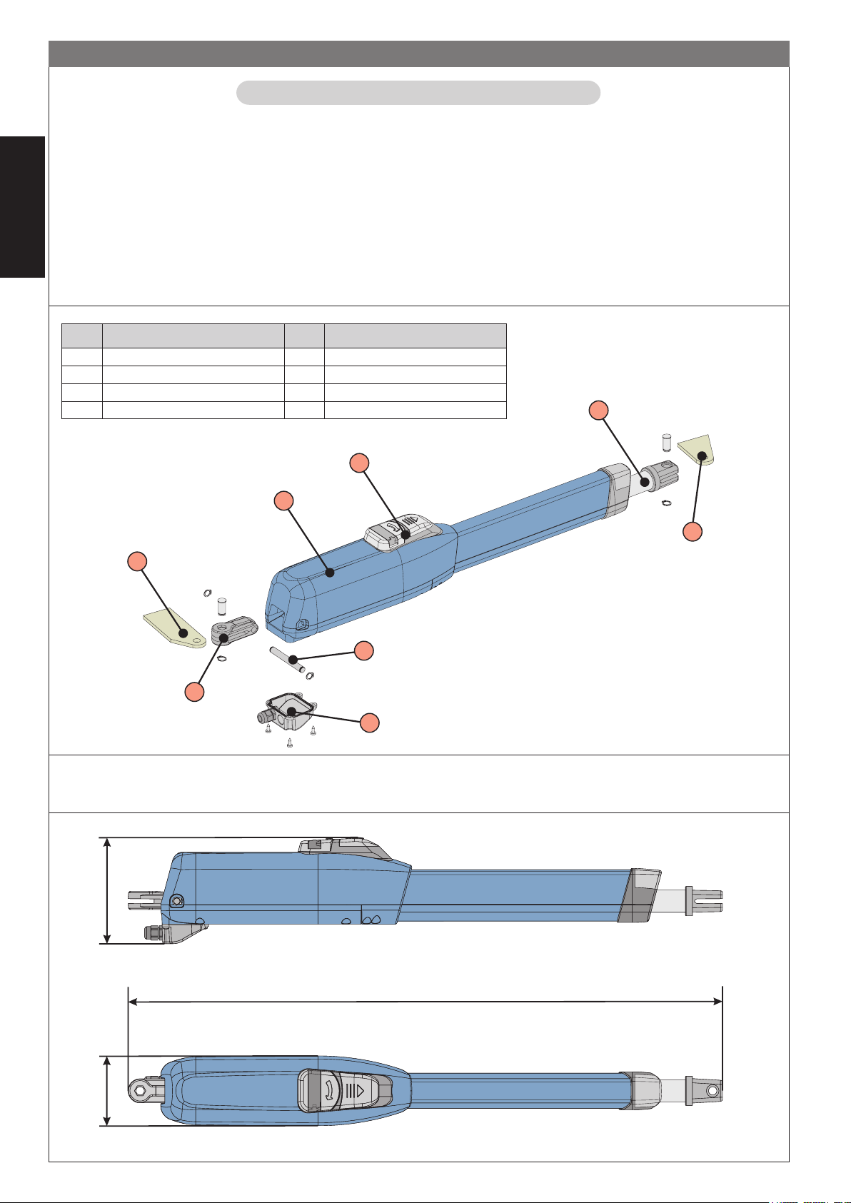
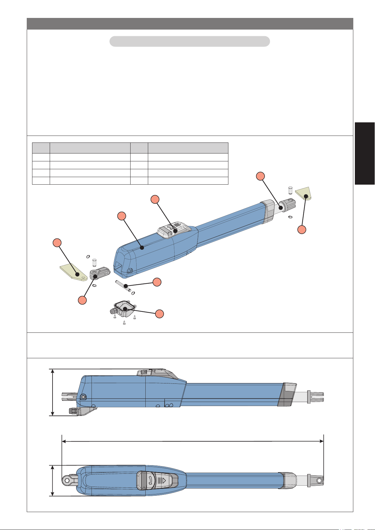
2. DESCRIZIONE
L’automazione MISTRAL per cancelli a battente è un operatore elettromeccanico irreversibile che trasmette il movimento all’anta
tramite un sistema a vite senza fine.
L’operatore, disponibile in più versioni, copre tutte le esigenze di installazione. Le versioni “LS” dispongono di finecorsa in apertura e
chiusura.
Il sistema irreversibile garantisce il blocco meccanico dell’anta quando il motore non è in funzione. Un comodo e sicuro sistema di
sblocco con chiave personalizzata permette la movimentazione manuale dell’anta in caso di disservizio o di mancanza di
alimentazione.
ATTENZIONE:
• Il corretto funzionamento e le caratteristiche dichiarate si ottengono solo con accessori e dispositivi di sicurezza GENIUS.
ITALIANO
• La mancanza di un dispositivo di frizione meccanica richiede, per garantire la necessaria sicurezza antischiacciamento,
l’impiego di una centrale di comando con frizione elettronica regolabile.
• L’automazione MISTRAL è stata progettata e costruita per controllare l’accesso veicolare, evitare qualsiasi altro utilizzo.
.soP enoizircseD .soP enoizircseD
1erottudirotoM5eroiretsopaffatS
2occolbsidovitisopsiD6eroiretsopoccattA
3oletS7eroiretsopoccattaonreP
4eroiretnaaffatS8areittesromoihcrepoC
2
3
5
2.1. Dimensioni
155
1
4
7
6
8
Fig. 1
100
840 (MISTRAL 300)
935 (MISTRAL 400)
Fig. 2
2
Page 5
4
3. CARATTERISTICHE TECNICHE
EHCINCETEHCITSIRETTARAC 003
003
SL
004
004
SL
423
423
SL
424
424
SL
423
enoizatnemilA~V032cdV42~V511
)W(aznetoP00307003
)A(etnerroC3.13 5.2
)C°(enoizetorpomreT041- 041
dnoC8-52
)Fµ(erotasne
)Nad(atnipS003082003
)mm(asroC003004003004003004
)ces/mc(oletsaticsuàticoleV 6,158.1
)m(.xamatnA3
C°02aozzilituidazneuqerfeopiT
)1(
3S
3S
%03
%53
C°02aivitacidniaroilciC03~52~57
)2(
4
3S
3S
%03
%53
)1(
3
)2(
4
%001
3S
%03
~03~52~
)C°(etneibmaarutarepmeT 55+02-
)gK(erotarepooseP8.788.78 8.78
)mm(erotarepoazzehgnuL 2.gifidev
inoisnemiD 2.gifidev
)mm(erotarepo
enoizetorpidodarG 45PI
(1)
Con ante oltre 2.5 m è obbligatorio installare l’elettroserratura al fine di garantire il blocco dell’anta
(2)
Con ante oltre 3 m è obbligatorio installare l’elettroserratura al fine di garantire il blocco dell’anta
3.1. Versioni
OLLEDOM ENOISREV
003LARTSIM~V032elibisreverrierottudirotoM
SL003LARTSIM arusuihc/arutrepaniasrocenifnoce~V032elib
004LARTSIM~V032elibisreverrierottudirotoM
SL004LARTSIM arusuihc/arutrepaniasroceni
423LARTSIMcdV42elibisreverrierottudirotoM
SL423LARTSIM arusuihc/arut
424LARTSIMcdV42elibisreverrierottudirotoM
M arusuihc/arutrepaniasrocenifnocecdV42elibisreverrierottudirotoM
SL424LARTSI
-V511-003LARTSIM~V511elibisreverrierot
-V511-SL003LARTSIM arusuihc/arutrepaniasrocenifnoce~V511elibisreverrierottudirotoM
RTSIM~V511elibisreverrierottudirotoM
-V511-004LA
-V511-SL004LARTSIM arusuihc/arutrepaniasrocenifnoce~V511elibisrever
tudirotoM
isreverrierottudirotoM
fnoce~V032elibisreverrierottudirotoM
repaniasrocenifnocecdV42elibisreverrierottudirotoM
rierottudirotoM
SL423
-V511-
-V511-
-V511-
424
SL424
-V511-
ITALIANO
)1(
3
3S
%53
)2(
4
3S
%03
3S
%53
Nel caso di operatori omologati CSA-UL, al fine di mantenere l’omologazione, è necessario utilizzare la centralina
455 MPS UL 115
4. INSTALLAZIONE
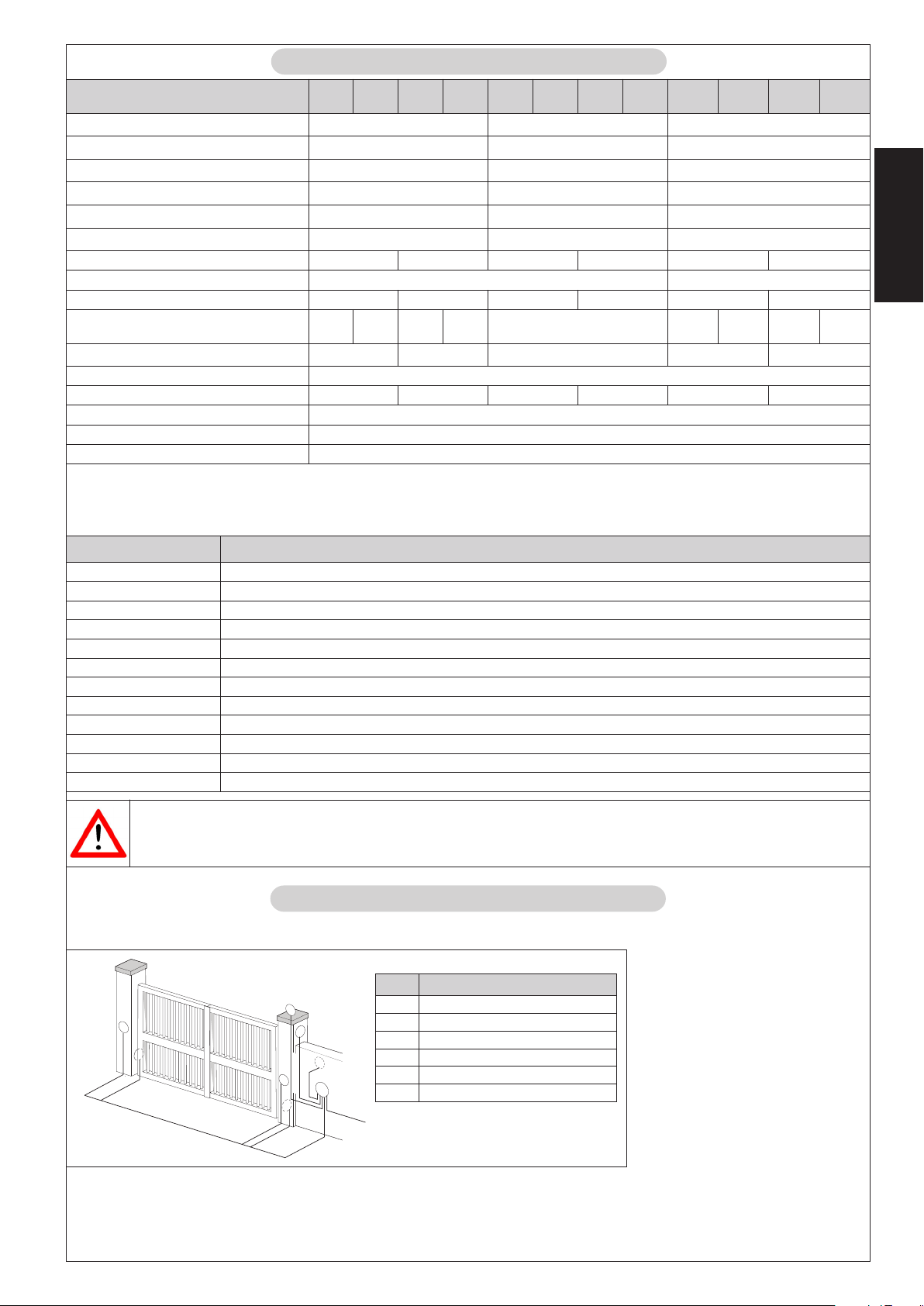
4.1. Predisposizioni elettriche (impianto standard)
.soP enoizircseD
6
1
Tx
2
2
m
2
m
m
,5
1
m
x
,5
0
x
2
4x1,5 mm
2
m
m
,5
1
2
x
2
1
x
R
2
2
2
m
3x0,5 m
5
2
4
m
m
m
m
,5
,5
0
0
x
3
3
x
2
3x
1,5 m
230 V~
1irotarepO
2elullecotoF
3acinorttelearutaihccerappA
4evaihcaetnasluP
5etneveciR
6erotaiggepmaL
2
m
3
Note:
• Per la messa in opera dei cavi elettrici utilizzare adeguati tubi rigidi e/
o flessibili
• Per evitare qualsiasi interferenza si
consiglia di separare sempre i cavi
di collegamento degli accessori a
bassa tensione e di comando da
quelli di alimentazione a 230/115 V~
utilizzando guaine separate.
Fig. 3
Page 6
4.2. Verifiche preliminari
Per un corretto funzionamento dell’automazione la struttura del cancello esistente, o da realizzare, deve presentare i seguenti
requisiti:
• gli elementi costruttivi meccanici devono essere in accordo con quanto stabilito dalle Norme EN 12604 e EN 12605.
• lunghezza dell’anta conforme con le caratteristiche del operatore .
• struttura delle ante robusta e rigida, idonea per l’automazione
• movimento regolare ed uniforme delle ante, privo di attriti ed impuntamento lungo tutta l’apertura
• cerniere adeguatamente robuste ed in buono stato
• presenza delle battute meccaniche di finecorsa sia in apertura che in chiusura
• presenza di un’efficiente presa di terra per il collegamento elettrico dell’operatore
Si raccomanda di effettuare gli eventuali interventi fabbrili prima di installare l’automazione.
Lo stato della struttura del cancello influenza direttamente l’affidabilità e la sicurezza dell’automazione.
ITALIANO
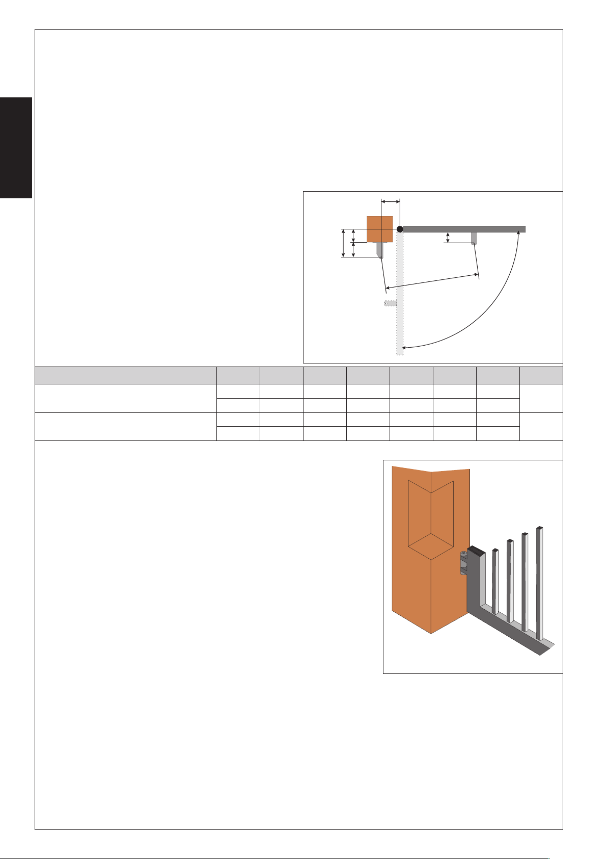
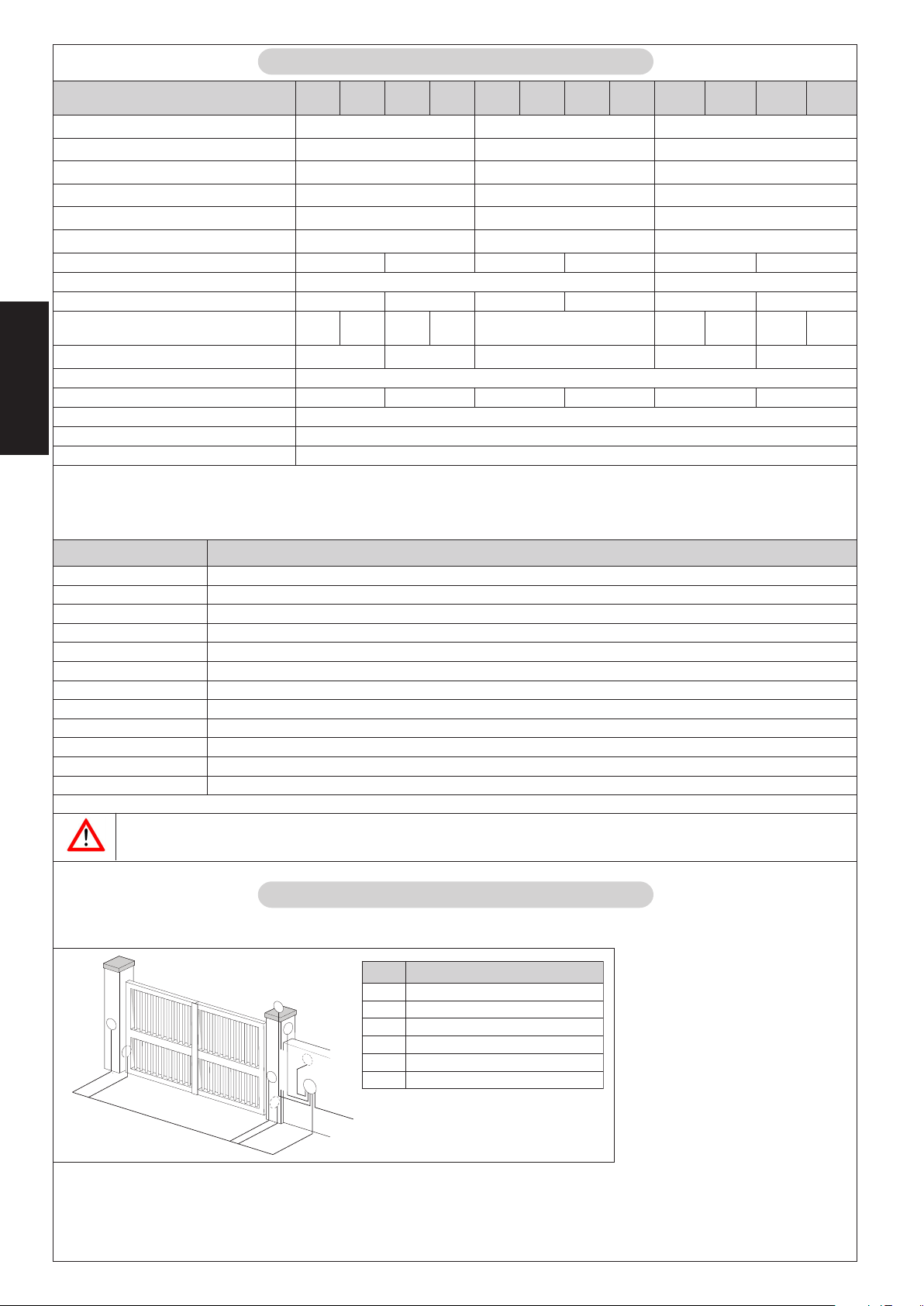
4.3. Quote di installazione
Determinare la posizione di montaggio dell’operatore facendo
riferimento alla Fig.4.
Verificare attentamente che la distanza tra l’anta aperta ed
eventuali ostacoli (pareti, recinzioni etc.) sia superiore all’ingombro dell’operatore.
(1)
corsa utile dell’operatore
olledoM
-V511-003/423/003LARTSIM
-V511-004/424/004LARTSIM
(2)
quota massima
α
°0954154109258060111
°01102153159206060111
°09591591093521070921
°01107
A B C
1071093011060921
(3)
quota minima
4.3.1. Regole generali per la determinazione delle quote di installazione
• per ottenere aperture dell’anta a 90° : A+B=C
• per ottenere aperture dell’anta superiori a 90° : A+B<C
• quote A e B più basse determinano velocità periferiche dell’anta più elevate
• limitare la differenza tra la quota A e la quota B entro 4 cm: differenze superiori
causano variazioni elevate della velocità durante in moto di apertura e chiusura
del cancello.
• mantenere una quota Z in modo tale che l’operatore non urti contro il pilastro.
• con le versioni LS i finecorsa intervengono per i primi ed ultimi 30 mm. È quindi
necessario utilizzare delle quote A e B tali da sfruttare tutta la corsa dell’operatore.
Corse minori potrebbero limitare od azzerare il campo di regolazione dei finecorsa.
D
A
Z
B
E
L
a
Fig. 4
)1(
)2(
D
)3(
Z
L E
)3(
54
54
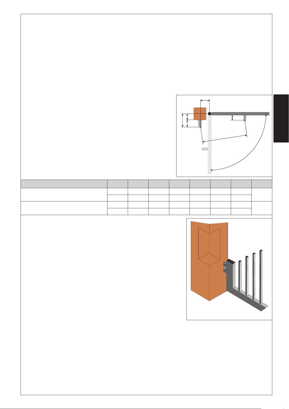
Nel caso in cui le dimensioni del pilastro o la posizione della cerniera non permettano
l’installazione dell’operatore, per mantenere la quota A determinata sarà necessario eseguire una nicchia sul pilastro come indicato in Fig.5. Le dimensioni della nicchia
devono essere tali da consentire un’agevole installazione, rotazione dell’operatore
ed azionamento del dispositivo di sblocco.
4
Fig. 5
Page 7
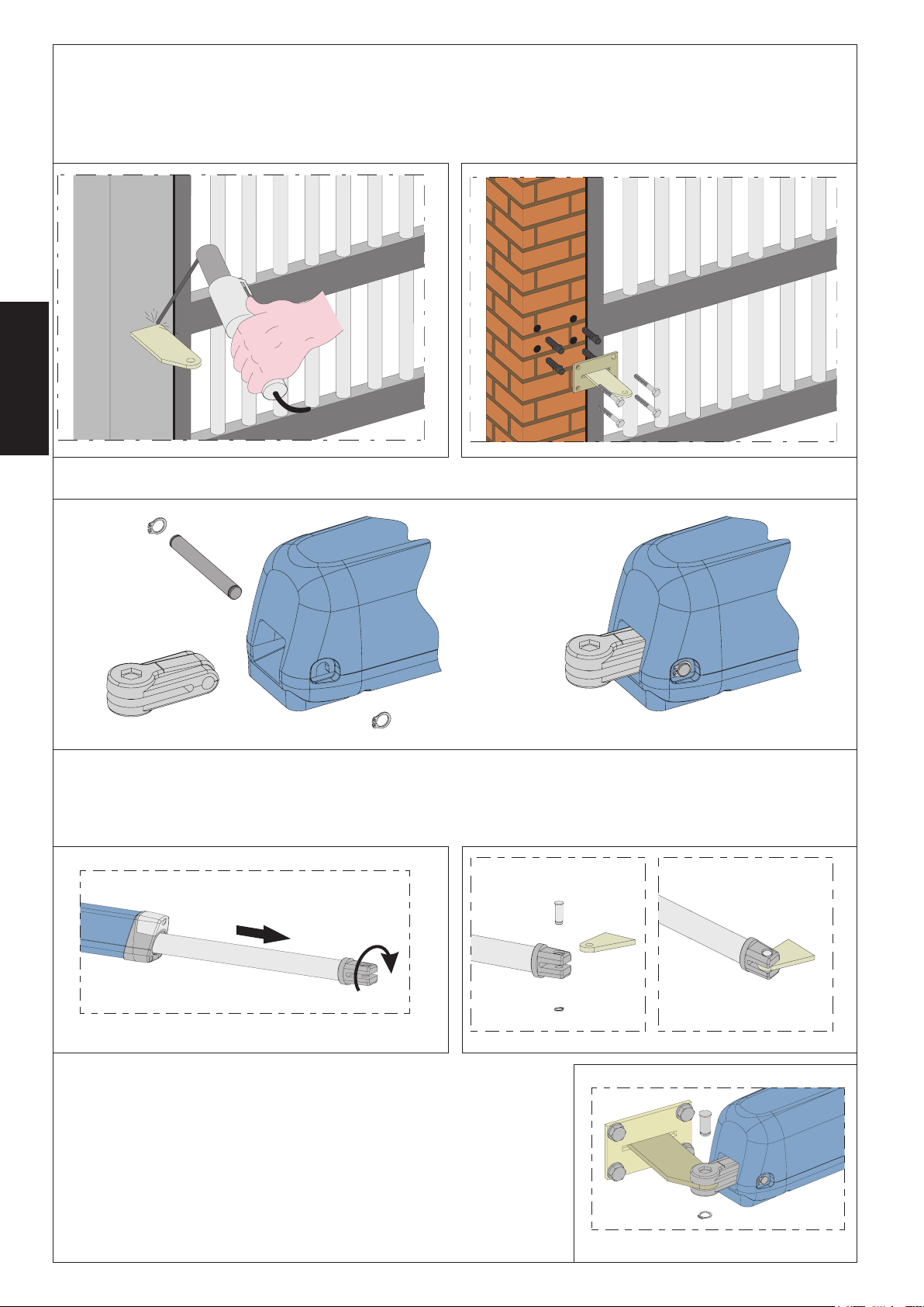
4.4. Installazione degli operatori
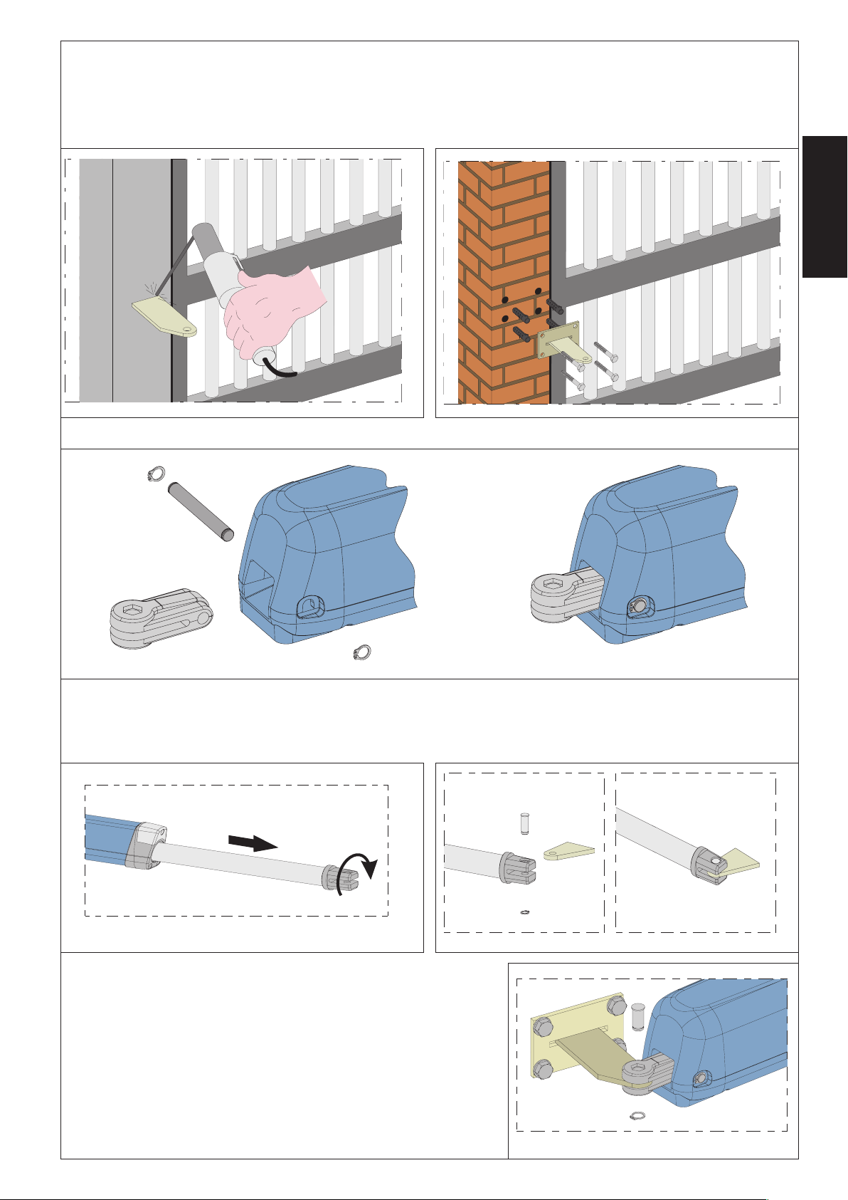
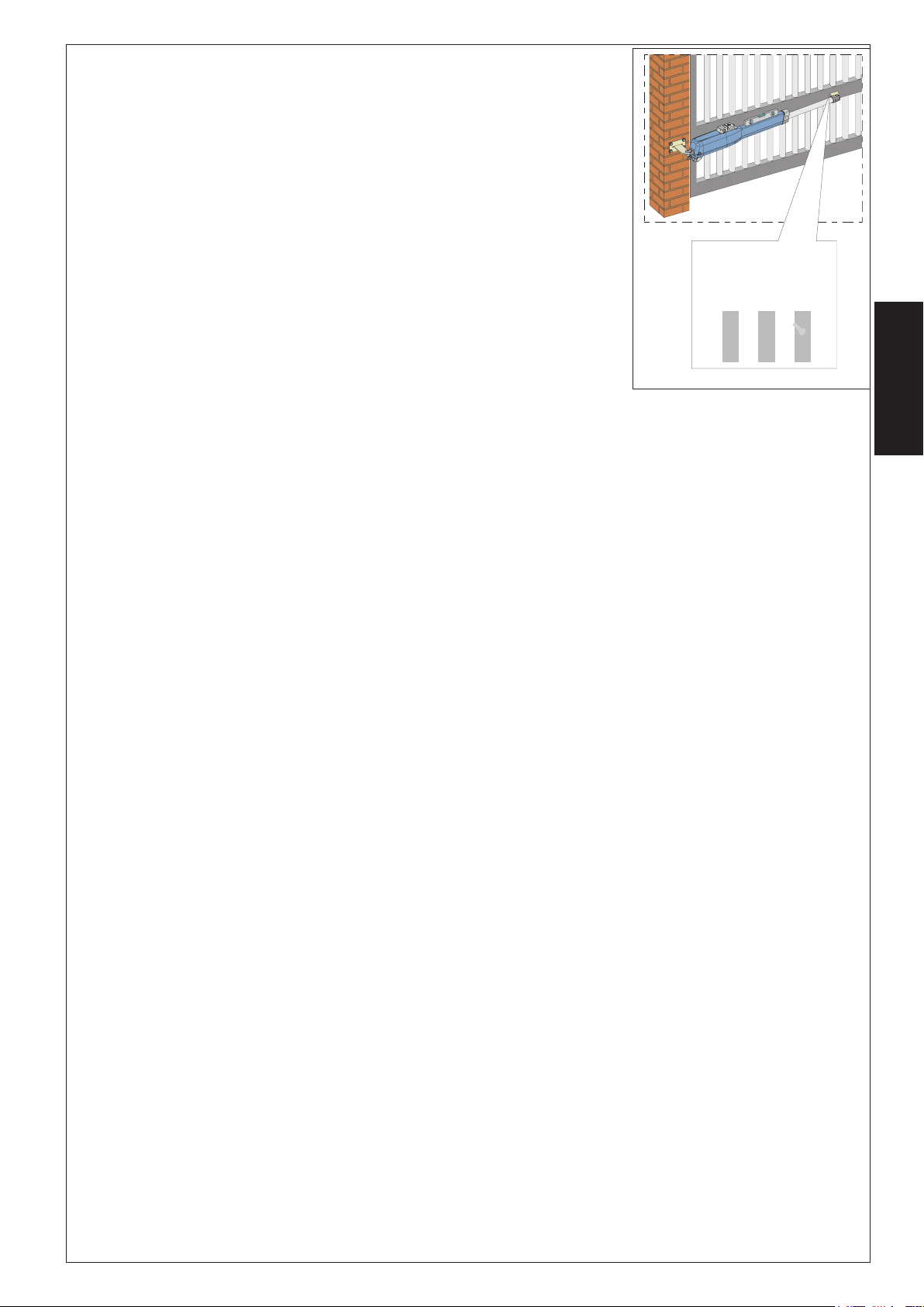
1) Fissare la staffa posteriore nella posizione determinata precedentemente. Nel caso di pilastro in ferro saldare accuratamente la
staffa direttamente sul pilastro (Fig.6). Nel caso di pilastro in muratura, utilizzare l’apposita piastra (optional) per il fissaggio ad
avvitare (Fig.7) utilizzando adeguati sistemi di fissaggio. Saldare quindi accuratamente la staffa alla piastra.
Durante le operazioni di fissaggio verificare con una livella la perfetta orizzontalità della staffa.
ITALIANO
Fig. 6
2) Assemblare l’attacco posteriore all’operatore come indicato in Fig.8.
3) Predisporre l’operatore per il funzionamento manuale (vedi par.6 )
4) Estrarre completamene lo stelo fino a battuta, fig.9 rif.1.
5) Ribloccare l’operatore (vedi par.6.1 )
6) Ruotare di mezzo / un giro lo stelo in senso orario, Fig.9 rif.2
7) Assemblare la staffa anteriore come indicato in Fig.10.
Fig. 7
Fig. 8
1
2
Fig. 9
8) Fissare l’operatore alla staffa posteriore tramite i perni in dotazione come
indicato in Fig.11.
5
Fig. 10
Fig. 11
Page 8
9) Chiudere l’anta e, mantenendo l’operatore perfettamente orizzontale, individuare il punto di
fissaggio della staffa anteriore (Fig.12).
10) Fissare provvisoriamente la staffa anteriore tramite due punti di saldatura (Fig.12).
Nota bene: nel caso la struttura del cancello non
permetta un solido fissaggio della staffa è
necessario intervenire sulla struttura del cancello
creando una solida base d’appoggio.
11) Sbloccare l’operatore (vedi par. 6) e verificare
manualmente che il cancello sia libero di aprirsi
completamente fermandosi sugli arresti meccanici di finecorsa e che il movimento dell’anta sia
ITALIANO
regolare e privo di attriti.
12) Eseguire gli interventi correttivi necessari e ripetere dal punto 8.
13) Svincolare momentaneamente l’operatore
dalla staffa anteriore e saldare definitivamente
la staffa.
Fig. 12
Nel caso la struttura dell’anta non permetta di
saldare la staffa è possibile utilizzare l’apposita staffa ad avvitare (optional), utilizzando adeguati sistemi di fissaggio (Fig.13).
Agire quindi come riportato per la staffa a saldare
Nota bene: è consigliato ingrassare tutti i perni di fissaggio degli attacchi.
4.5. Cablaggio dell’operatore
Fig. 13
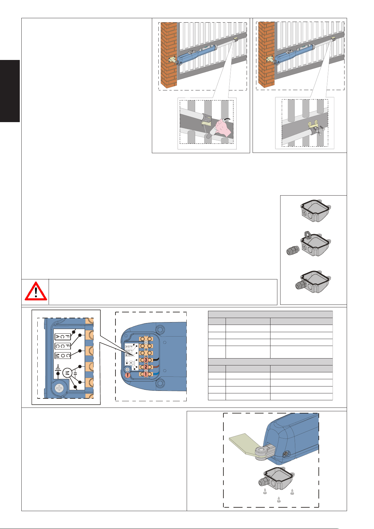
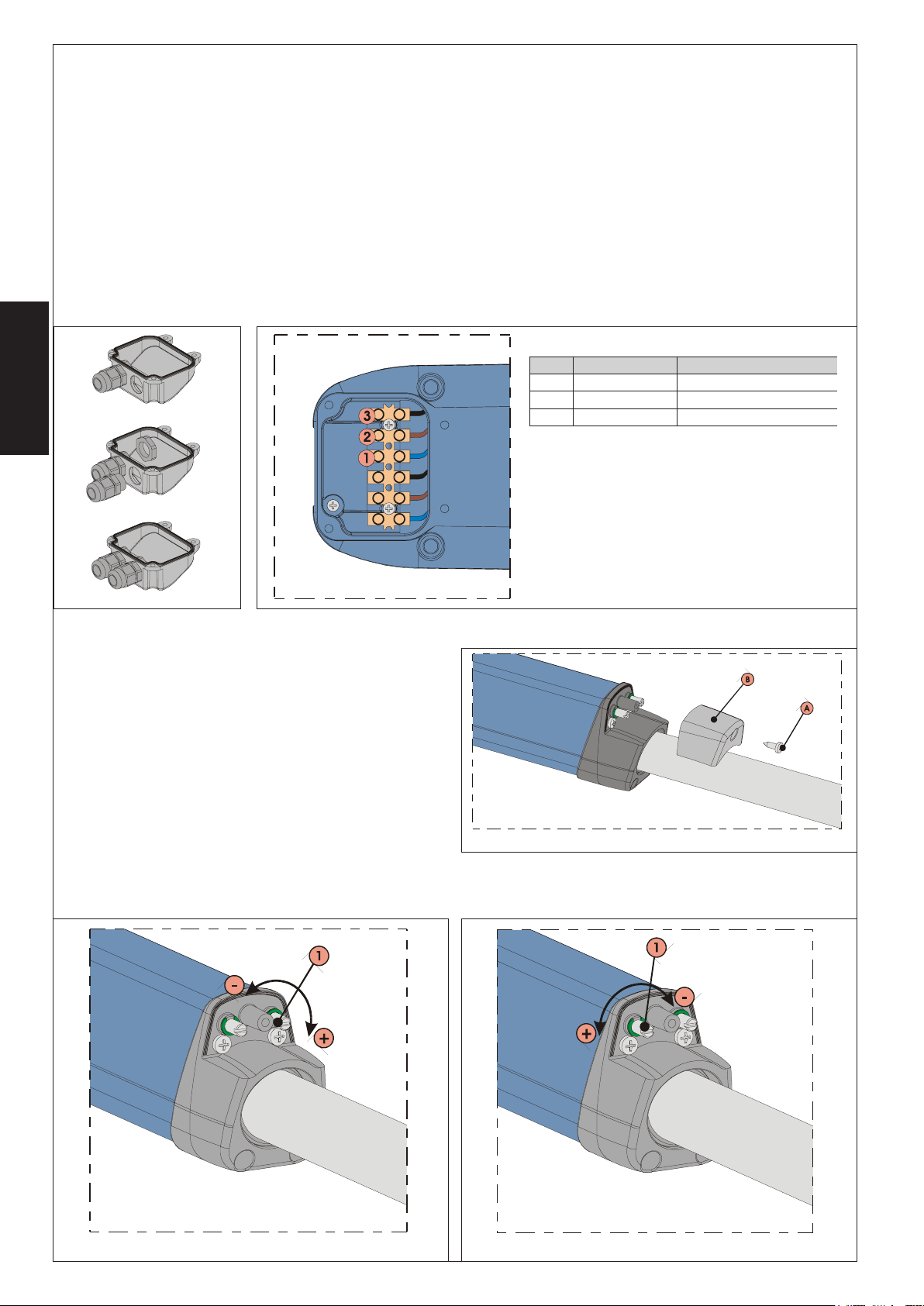
Nella parte inferiore dell’operatore è stata alloggiata una morsettiera per il collegamento del motore,
degli eventuali finecorsa e per la messa a terra dell’operatore.
ATTENZIONE: Per il collegamento del motore deve essere utilizzato il cavo in dotazione per il tratto
mobile o in alternativa un cavo per posa mobile da esterno.
Per il cablaggio del motore agire come segue:
1) Liberare uno dei due fori prefatturati sul coperchietto in dotazione, Fig.14, nel caso di operatori con
finecorsa devono essere liberati entrambi i fori.
2) Montare il pressacavo in dotazione.
3) Eseguire i collegamenti del motore e della massa a terra facendo riferimento alla Fig.15 ed alla
tabella.
Per gli operatori omologati CSA-UL è obbligatorio, al fine di mantenere l’omologazione,
posizionare il condensatore fissato in modo stabile all’interno di un contenitore
omologato CSA-UL.
.SOP EROLOC ENOIZIRCSED
1 )ocnaiB(ulBenumoC
2 )ossoR(enorraM1esaF
3 )oreN(oreN2esaF
T
.SOP EROLOC ENOIZIRCSED
1 ulB1esaF
2 otazzilitunoN/
3 enorraM2esaF
T otazzilitunoN/
edreV/ollaiG
)edreV(
4) Chiudere il coperchio con le quattro viti in dotazione, Fig.17.
Fig. 14
)~V511(~V032LARTSIM
arretaasseM
cdV42LARTSIM
Fig. 15
Fig. 16
6
Page 9
4.6. Finecorsa
I modelli “LS” dispongono di finecorsa sia in apertura che in chiusura, richiedono quindi l’utilizzo di una apparecchiatura elettronica in grado di gestire questi ingressi.
Nota bene: I finecorsa intervengono per i primi ed ultimi 30 mm della corsa. È quindi necessario che l’operatore, durante la fase
di apertura, utilizzi tutta la corsa a disposizione. Corse minori possono limitare od annullare completamente il campo di regolazione
dei finecorsa.
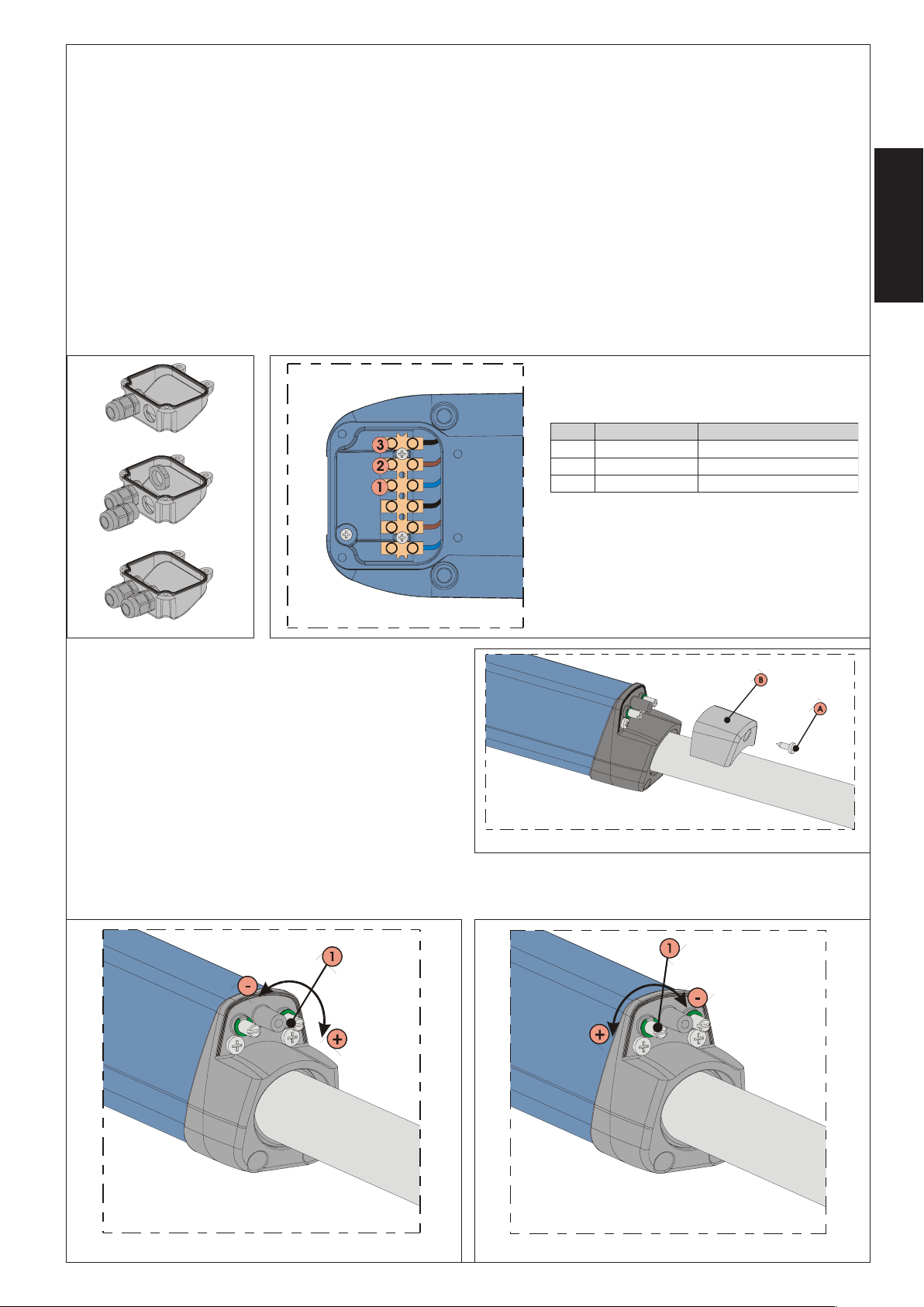
4.6.1. Cablaggio dei finecorsa
Il cablaggio dei finecorsa viene realizzato nella stessa morsettiera dove è stato eseguito il cablaggio del motore. Per eseguire il
cablaggio dei finecorsa procedere come segue:
1) Aprire anche il secondo foro prefatturato sul coperchietto, Fig.17.
2) Montare il passacavo in dotazione, Fig.17.
3) Infilare il cavo e collegarlo ai morsetti rispettando i colori specificati nella tabella di Fig.18.
4) Chiudere il coperchio con le quattro viti in dotazione.
Note bene:
• Per il collegamento dei finecorsa utilizzare cavo per posa mobile da esterno con conduttori di sezione 0.5 mm2.
• Durante il cablaggio fare attenzione ai colori dei fili come specificato nella tabella in Fig.18.
.SOP EROLOC ENOIZIRCSED
1 ulBenumoC
2 enorraM)CCF(arusuihcidasroceniF
3 oreN)ACF(arutrepaidasroceniF
ITALIANO
Fig. 17
4.6.2. Regolazione dei finecorsa
Per eseguire la regolazione dei finecorsa procedere come segue:
1) Svitare la vite di fissaggio superiore, Fig.19 rif.A, e sfilare il coperchietto, Fig.19 rif.B.
2) Per regolare il finecorsa di chiusura FCC agire sulla vite di
regolazione, Fig.20 rif.1, ruotandola in senso orario per aumentare la corsa dello stelo e, viceversa, in senso antiorario per
ridurla.
3) Per regolare il finecorsa di apertura FCA agire sulla vite di regolazione, Fig.21 rif.1, ruotandola in senso antiorario per aumentare la corsa dello stelo e, viceversa, in senso orario per ridurla.
4) Eseguire un paio di cicli di prova per verificare il corretto posizionamento del finecorsa. Qualora fosse necessario regolare
nuovamente i finecorsa ripetendo dal punto 2.
5) Riposizionare coperchietto, Fig.19 rif.B, e serrare nuovamente la vite di fissaggio, Fig.19 rif.A.
Fig. 18
Fig. 19
Fig. 20
Fig. 21
7
Page 10
4.7. Messa in funzione
ATTENZIONE: Prima di effettuare qualsiasi intervento sull’impianto o sull’operatore, togliere l’alimentazione elettrica.
Seguire scrupolosamente i punti 10, 11, 12, 13 e 14 degli OBBLIGHI GENERALI PER LA SICUREZZA.
Seguendo le indicazioni di Fig.3, predisporre le canalizzazioni ed effettuare i collegamenti elettrici dell’apparecchiatura elettronica
e degli accessori prescielti.
Separare sempre i cavi di alimentazione da quelli di comando e di sicurezza (pulsante, ricevente, fotocellule, etc.). Per evitare di
portare in centrale disturbi elettrici utilizzare guaine separate.
1) Alimentare il sistema e verificare lo stato dei leds come dalla tabella riportata nelle istruzioni dell’apparecchiatura elettronica.
2) Programmare l’apparecchiatura elettronica secondo le proprie esigenze come da relative istruzioni.
5. PROVA DELL’AUTOMAZIONE
• Procedere alla verifica funzionale ed accurata dell’automazione e di tutti gli accessori ad essa collegati, prestando particolare
attenzione ai dispositivi di sicurezza.
ITALIANO
• Consegnare all’utilizzatore finale il fascicolo “Guida per l’Utente” ed il foglio di Manutenzione.
• Illustrare ed istruire correttamente l’utilizzatore sul corretto funzionamento ed utilizzo dell’automazione.
• Segnalare all’utilizzatore le zone di potenziale pericolo dell’automazione.
6. FUNZIONAMENTO MANUALE
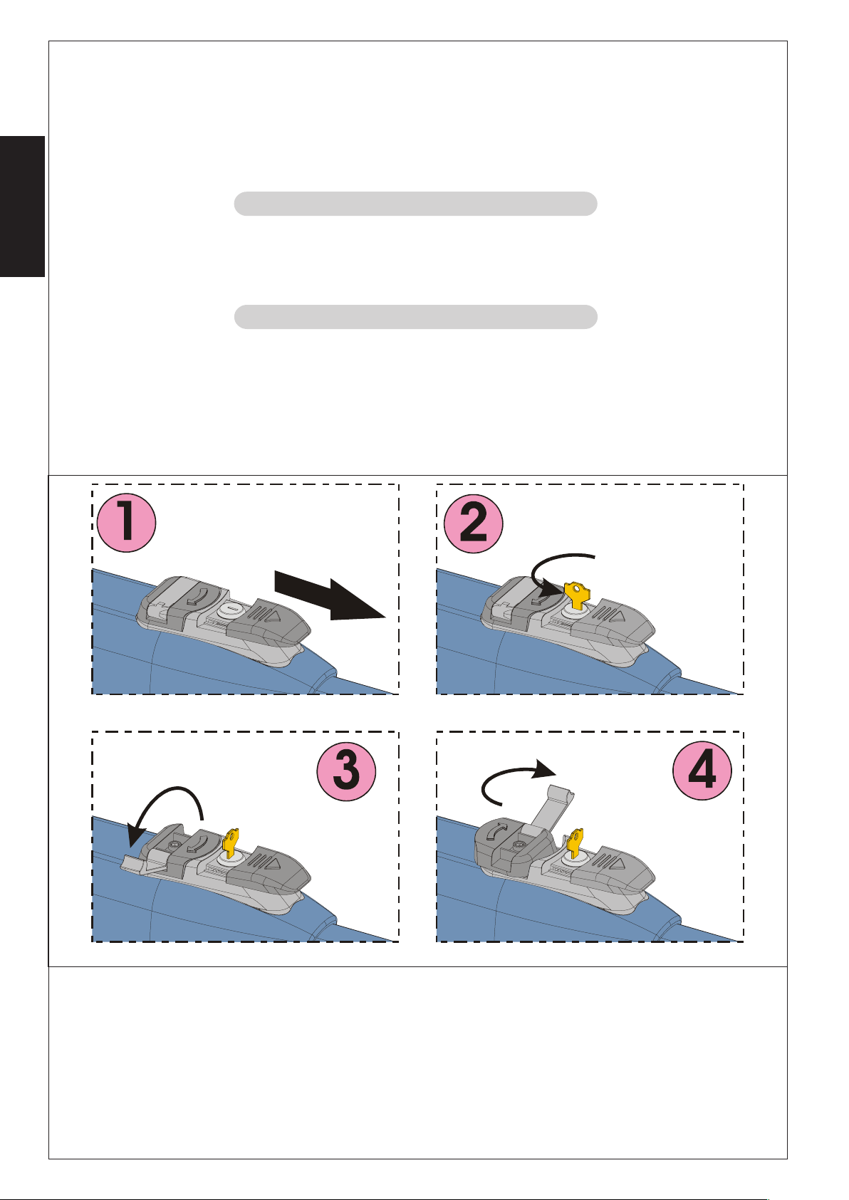
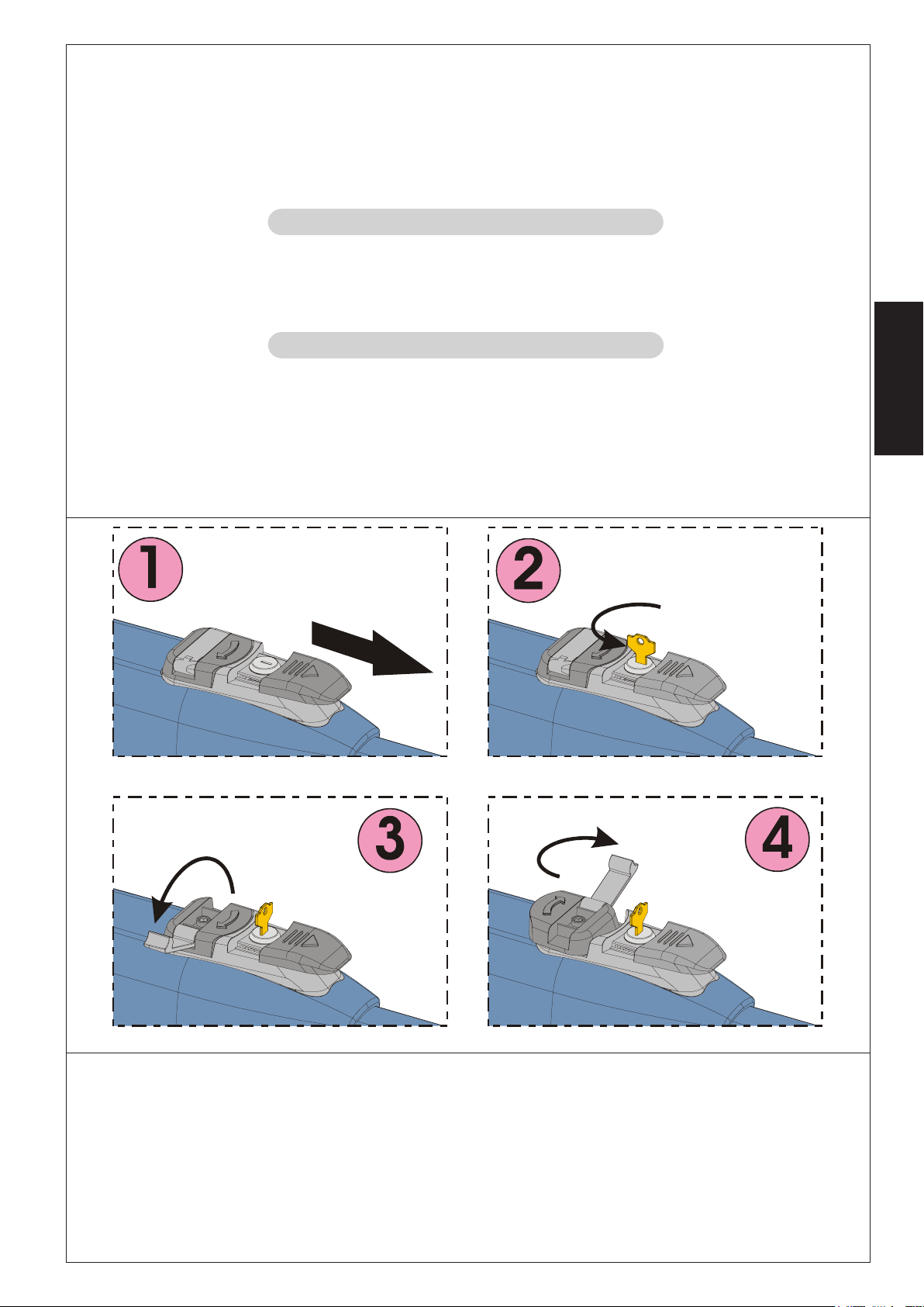
Nel caso si renda necessario movimentare manualmente l’automazione, per mancanza di alimentazione o disservizio dell’operatore, agire come di seguito:
1) Togliere l’alimentazione elettrica agendo sull’interruttore differenziale (anche in caso di mancanza di alimentazione).
2) Far scorrere il cappuccio protettivo, Fig.22/1.
3) Inserire la chiave e ruotarla di 90°, Fig.22/2.
4) Sollevare la leva di manovra, Fig.22/3.
5) Per sbloccare l’operatore ruotare di 180° la leva di manovra nella direzione della freccia presente sul sistema di sblocco, Fig.22/
4.
6) Effettuare manualmente la manovra di apertura o di chiusura dell’anta.
Fig. 22
Nota bene: Per mantenere l’operatore in funzionamento manuale è assolutamente necessario lasciare il dispositivo di sblocco
nella posizione attuale e l’impianto disalimentato.
6.1. Ripristino del funzionamento normale
Per ripristinare le condizioni di funzionamento normale agire come di seguito:
1) Ruotare il sistema di sblocco di 180° nella direzione opposta a quella indicata dalla freccia.
2) Ruotare di 90° la chiave di sblocco ed estrarla.
3) Richiudere la leva di comando ed il coperchietto di protezione.
4) Alimentare l’impianto ed eseguire alcune manovre per verificare il corretto ripristino di tutte le funzioni dell’automazione.
8
Page 11

7. MANUTENZIONE
Al fine d’assicurare nel tempo un corretto funzionamento ed un costante livello di sicurezza è opportuno eseguire, con cadenza
semestrale, un controllo generale dell’impianto. Nel fascicolo “Guida per l’Utente” è stato predisposto un modulo per la registrazione degli interventi.
8. RIPARAZIONE
Per eventuali riparazioni rivolgersi ai Centri Riparazione autorizzati.
9. ACCESSORI DISPONIBILI
Per gli accessori disponibili fare riferimento al catalogo.
10. APPLICAZIONI PARTICOLARI
Non sono previste applicazioni diverse da quella descritta
ITALIANO
9
Page 12

CONTENTS
Declaration of conformity pag.10
Description pag.11
Installation pag.12
Technical specifications pag.12
Testing the automated system pag.17
Manual operation pag.17
Maintenance pag.18
Repairs pag.18
ENGLISH
Available accessories pag.18
Special applications pag.18
CE DECLARATION OF CONFORMITY FOR MACHINES
(DIRECTIVE 98/37/CE)
Manufacturer: GENIUS S.p.a.
Address: Via Padre Elzi, 32 - 24050 - Grassobbio BERGAMO - ITALY
Declares that: MISTRAL mod. operator
• is built to be integrated into a machine or to be assembled with other machinery to create a machine under the provisions of
Directive 98/37/CE;
• conforms to the essential safety requirements of the following EEC directives:
73/23 EEC and subsequent amendment 93/68/EEC.
89/336 EEC and subsequent amendment 92/31/EEC and 93/68/EEC
and also declares that the machinery must not be put into service until the machine in which it will be integrated or of which it will
become a component has been identified and declared as conforming to the provisions of Directive 98/37/CE.
Grassobbio, 01-06-2005
The Managing Director
D.Gianantoni
10
Page 13
AUTOMATED SYSTEM MISTRAL
2. DESCRIPTION
The MISTRAL automated system for swing gates is an electro-mechanical non-reversing operator that transmits motion to the leaf via
a worm screw system.
The operator is available in many versions covering therefore every installation requirement. The “LS” versions are equipped with
opening and closing limit switches.
The non-reversing system ensures the leaf is mechanically locked when the motor is not operating. A convenient and safe release
system with customised key makes it possible to manually move the leaf in the event of a malfunction or of a power failure.
ATTENTION:
• The correct operation and the declared specifications only apply if GENIUS accessories and safety devices are used.
• As no mechanical clutch device is fitted, a control unit with adjustable electronic clutch is required to ensure the necessary anti-
crushing safety.
• The MISTRAL automated system was designed and built for controlling vehicle access. Avoid any other use whatever.
.soP noitpircseD .soP noitpircseD
1rotomraeG5tekcarbraeR
2ecivedesaeleR6gnittifraeR
3doR7nipgnittifraeR
4tekcarbtnorF8revocdraoblanimreT
2
3
ENGLISH
5
2.1. Dimensions
1
4
7
6
8
Fig. 1
155
100
840 (MISTRAL 300)
935 (MISTRAL 400)
Fig. 2
11
Page 14
4
3. TECHNICAL SPECIFICATIONS
SNOITACIFICEPSLACINHCET 003
003
SL
004
004
SL
423
423
SL
ylppusrewoP~V032cdV42~V511
)W(rewoP00307003
)A(tnerruC3.13 5.2
)C°(noitcetorplamrehT041- 041
)Fµ(roticapaC8-52
)
Nad(tsurhT003082003
)mm(levarT003004003004003004
)ces/mc(deepsnoisnetxedoR 6,158.1
)m(.xamfaeL3
C°02taycneuqerfesudnaepyT
)1(
3S
3S
%03
%53
C°02taruoh/elcycetamixorppA03~52~57
)2(
4
3S
3S
%03
%53
)1(
3
%001
~03~52~
)C°(erutarepmettneibmagnitarepO 55+02-
)gK(thgiewrotarepO8.788.78 8.78
ENGLISH
)mm(htgnelrotarepO 2.gifees
nemidrotarepO 2.gifees
)mm(snois
ssalcnoitcetorP 44PI
(1)
With leaves exceeding 2.5 m the fitting of an electric lock is required to ensure the leaf locking
(2)
With leaves exceeding 3 m the fitting of an electric lock is required to ensure the leaf locking
3.1. Versions
424
424
SL
)2(
4
423
-V511-
3
3S
%03
SL423
424
-V511-
)1(
3S
%53
-V511-
4
3S
%03
SL424
-V511-
)2(
3S
%53
LEDOM NOISREV
003LARTSIMrotomraeggnisrever-non~V032
SL003LARTSIM sehctiwstimilgnisolc/gninepohtiwrotomraeggnisr
ever-non~V032
004LARTSIMrotomraeggnisrever-non~V032
SL004LARTSIM sehctiwstimilgnisolc/gninepohtiwrotomrae
423LARTSIMrotomraeggnisrever-noncdV42
SL423LARTSIM sehctiwstimilgnisolc/gninepohtiwro
424LARTSIMrotomraeggnisrever-noncdV42
SL424LARTSIM sehctiwstimilgnisolc/gninepo
-V511-003LARTSIMrotomraeggnisrever-non~V511
-V511-SL003LARTSIM sehctiwsti
-V511-004LARTSIMrotomraeggnisrever-non~V511
4LARTSIM sehctiwstimilgnisolc/gninepohtiwrotomraeggnisrever-non~V511
-V511-SL00
For CSA-UL approved operators, control unit 455 MPS UL 115 must be used in order to maintain the approval.
4.1. Electrical set-up (standard system)
6
1
2
x1,5 mm
2x0,5 mm
x
T
2
2
1
x
4
5
2
m
m
,5
1
2
2
x
4
m
2
m
m
m
,5
1
,5
0
0
x
3
3
x
2
Rx
2
2
m
2
m
,5
m
m
,5
0
x
3
ggnisrever-non~V032
tomraeggnisrever-noncdV42
htiwrotomraeggnisrever-noncdV42
milgnisolc/gninepohtiwrotomraeggnisrever-non~V511
4. INSTALLATION
.soP noitpircseD
1srotarepO
2sllecotohP
3draoblortnoC
4nottubhsupyeK
5revieceR
6pmalgnihsalF
3
x
1
,5
m
2
m
2
3
0
V
~
Notes:
• Use suitable tubes and/or hoses to
lay electric cables
• To avoid any kind of interference
always separate low-voltage
accessories and control cables
from 230/115 V~ power supply
cables using separate sheaths.
Fig. 3
12
Page 15
A
Z
D
B
L
a
E
4.2. Preliminary checks
To ensure a correct operation of the automated system, make sure the following requirements are observed as for the gate structure
(existing or to be created):
• the mechanical parts must conform to the provisions of Standards EN 12604 and EN 12605.
• leaf length in compliance with the operator specifications.
• sturdy and stiff structure of the leaves, suitable for automation
• regular and uniform movement of the leaves, without any friction and dragging during their entire opening
• stiff hinges in good conditions
• presence of both opening and closing mechanical limit stops
• presence of an efficient earthing for electrical connection of the operator
Perform any necessary metalwork job before installing the automated system.
The condition of the gate structure directly affects the reliability and safety of the automated system.
4.3. Installation dimensions
Determine the fitting position of the operator with reference to Fig.4.
Check with care if the distance between the open leaf and any obstacles
(walls, fences etc.) is higher than the operator dimensions
ENGLISH
(1)
operator useful travel
ledoM
-V511-003/423/003LARTSIM
-V511-004/424/004LARTSIM
(2)
max. dimension
α
°0954154109258060111
°01102153159206060111
°09591591093521070921
°01107
A B C
1071093011060921
(3)
min. dimension
4.3.1. General rules to determine the installation dimensions
• to obtain 90° leaf openings : A+B=C
• to obtain leaf openings exceeding 90° : A+B<C
• Smaller A and B dimensions determine higher peripheral speed of the leaf.
• Limit the difference between A and B dimension within 4 cm: higher differences
cause great speed variations during the gate opening and closing movement.
• Keep a Z dimension in such a way that the operator does not strike the pillar.
• in the LS versions the limit switches are triggered for the first and the last 30 mm.
Therefore use such A and B dimensions in order to use the whole operator travel.
Shorter travels could limit or cancel the limit switch adjustment range.
If the pillar dimensions or the hinge position do not allow the installation of the operator,
a niche on the pillar, as shown in Fig. 5, should be created in order to maintain the A
dimension as determined. The niche should be dimensioned in such a way to enable
easy installation, operator rotation and operation of the release device.
Fig. 4
)1(
)2(
D
)3(
Z
L E
)3(
54
54
Fig. 5
13
Page 16
4.4. Installing the operators
1) Fix the rear bracket in the position determined before. In the event of iron pillar carefully weld the bracket directly on the pillar
(Fig.6). In the event of masonry pillar, use the suitable plate (optional) for the fixing to screw (Fig.7) by making use of suitable
fastening systems. Then carefully weld the bracket to the plate.
During the fastening operations, check if the bracket is perfectly horizontal by means of a level.
ENGLISH
Fig. 6
2) Assemble the rear fitting to the operator as shown in Fig.8.
Fig. 7
3) Set the operator for manual operation (see paragraph 6 )
4) Completely extend the rod till it reaches the limit stop, fig.9 ref.1.
5) Lock the operator again (see paragraph 6.1 )
6) Turn the rod clockwise half a revolution / a revolution, Fig.9 ref.2
7) Assemble the front bracket as shown in Fig.10.
1
2
Fig. 9
8) Fix the operator to the rear bracket by means of the supplied pins as shown in
Fig.11.
Fig. 8
Fig. 10
14
Fig. 11
Page 17
ENGLISH
15
Page 18
4.6. Limit switches
“LS” models are equipped with opening and closing limit switches. Therefore they require the use of a control board able to control
these inputs.
Note: Limit switches are triggered for the first and the last 30 mm of the travel. Therefore the operator should use the whole available
travel during the opening phase. Shorter travels can limit or completely cancel the limit switch adjustment range.
4.6.1. Wiring the limit switches
Limit switches are wired in the same terminal board where the motor wiring has been carried out. Wire the limit switches as follows:
1) Open the second pre-drilled hole in the cover, Fig.17.
2) Fit the supplied cable gland, Fig.17
3) Insert the cable and connect it to the terminals observing the colours specified in the table of Fig.18.
4) Close the cover with the four supplied screws.
Note:
• For limit switches connection use the cable for the external movable laying with wires having a cross section of 0.5 mm2.
• During the wiring operations, observe the wire colours as specified in the table of Fig.18.
.SOP RUOLOC NOITPIRCSED
1 eulBelbacnommoC
2 nworB)CCF(hctiwstimilgnisolC
ENGLISH
3 kcalB)ACF(hctiwstimilgninepO
Fig. 17
4.6.2. Adjusting limit switches
Limit switches adjustment is carried out as follows:
1) Unscrew the upper fastening screw, Fig.19 ref.A, and remove
the cap, Fig.19 ref.B.
2) To adjust the closing limit switch FCC turn the adjusting screw
clockwise, Fig.20 ref.1, to increase the rod stroke and counterclockwise to reduce it.
3) To adjust the opening limit switch FCA turn the adjusting screw
counter-clockwise, Fig.21 ref.1, to increase the rod stroke and
clockwise to reduce it.
4) Perform a pair of test cycles to check the correct position of
the limit switch. If the limit switches adjustment needs to be
carried out again, repeat the operation starting from point 2.
5) Riposition the cap, Fig.19 ref.B, and tighten the fastening screw
again, Fig.19 ref.A.
Fig. 18
Fig. 19
Fig. 20
Fig. 21
16
Page 19
4.7. Start-up
ATTENTION: Cut power before any job on the system or on the operator.
Carefully observe points 10, 11, 12, 13 and 14 of the SAFETY GENERAL RULES.
With reference to the indications in Fig.3, set the ducts and carry out the electrical connections of the control board and of the
chosen accessories.
Always separate power cables from control and safety cables (push button, receiver, photocells, etc.). To avoid any electrical noise
whatever in the unit, use separate sheaths.
1) Power up the system and check the LED condition as shown in the table of the control board instructions.
2) Program the control board according to the needs by following the given instructions.
5. TESTING THE AUTOMATED SYSTEM
• Carefully check operating efficiency of the automated system and of all accessories connected to it, paying special attention
to the safety devices.
• Hand the “User’s Guide” to the final user together with the Maintenance sheet.
• Explain correct operation and use of the automated system to the user.
• Indicate the potentially dangerous areas of the automated system to the user.
6. MANUAL OPERATION
If the automated system needs to be moved manually due to a power lack or to an operator malfunction, proceed as follows:
1) Cut power by means of the safety circuit breaker (even in the event of a power lack).
2) Slide the protective cap, Fig.22/1.
3) Insert the key and turn it 90°, Fig.22/2.
4) Lift the control lever, Fig.22/3.
5) To release the operator turn 180° the control lever to the direction indicated by the arrow on the release system, Fig.22/4.
6) Open and close the leaf manually.
ENGLISH
Fig. 22
Note: To hold the operator in manual operation the release device should be left in its current positions and the system should be
without power.
6.1. Restoring normal operation
To restore normal operating conditions, proceed as follows:
1) Turn the release system 180° in the opposite direction of the arrow.
2) Turn 90° the release key and remove it.
3) Close the control lever and the protection cover.
4) Power up the system and perform some movements in order to check the correct restoring of every function of the automated
system.
17
Page 20

7. MAINTENANCE
To ensure trouble-free operation and a constant safety level, an overall check of the system should be carried out every 6 months.
A form for recording operations has been included in the “User’s Guide” booklet.
8. REPAIRS
For any repairs, contact the authorised Repair Centres.
9. AVAILABLE ACCESSORIES
Refer to catalogue for available accessories.
10. SPECIAL APPLICATIONS
There is no special application other than the described use
ENGLISH
18
Page 21

INDEX
Déclaration de conformité pag.19
Description pag.20
Caractéristiques techniques pag.21
Installation pag.21
Essai de l’automatisme pag.26
Fonctionnement manuel pag.26
Entretien pag.27
Réparation pag.27
Accessoires disponibles pag.27
Applications particulières pag.27
DÉCLARATION CE DE CONFORMITÉ POUR MACHINES
(DIRECTIVE 98/37/CE)
Fabricant: GENIUS S.p.a.
Adresse: Via Padre Elzi, 32 - 24050 - Grassobbio BERGAMO - ITALIE
Déclare que: L’opérateur mod. MISTRAL
• est construit pour être incorporé dans une machine ou pour être assemblé à d’autres appareillages, afin de constituer une
machine conforme aux termes de la Directive 98/37/CE;
• est conforme aux conditions essentielles requises par les directives CEE suivantes:
73/23/CEE et modification 93/68/CEE successive.
89/336/CEE et modification 92/31/CEE et 93/68/CEE successive.
FRANÇAIS
et déclare, en outre, qu’il est interdit de mettre en service l’appareillage jusqu’à ce que la machine dans laquelle il sera incorporé
ou dont il deviendra un composant ait été identifiée et jusqu’à ce que la conformité aux conditions de la Directive 98/37/CE en
ait été déclarée.
Grassobbio, le 01-06-2005
L’administrateur Délégué
D.Gianantoni
19
Page 22

AUTOMATISME MISTRAL
2. DESCRIPTION
L’automatisme MISTRAL pour portails battants est un opérateur électromécanique irréversible qui transmet le mouvement au
vantail par l’intermédiaire d’un système à vis sans fin.
L’opérateur, disponible en plusieurs versions, répond à toutes les exigences d’installation. Les versions “LS” disposent d’un fin de
course en ouverture et fermeture.
Le système irréversible garantit le verrouillage mécanique du vantail quand le moteur n’est pas en fonction. Un système pratique et
sûr de déblocage à clé personnalisée permet l’actionnement manuel du vantail en cas de dysfonctionnement ou de coupure de
courant.
ATTENTION:
• Le fonctionnement correct et les caractéristiques déclarées n’est possible qu’avec les accessoires et les dispositifs de sécurité
GENIUS.
• L’absence d’un dispositif d’embrayage mécanique exige, pour garantir la sécurité anti-écrasement, une centrale de commande
à embrayage électronique réglable.
• L’automatisme MISTRAL a été conçu et construit pour contrôler l’accès de véhicules; éviter toute autre utilisation.
.soP noitpircseD .soP noitpircseD
1ruetcudérotoM5erueirétsopettaP
2egacolbédedfitisopsiD6erueirétsopehcatta'dettaP
3egiT7
4erueirétnaettaP8reinrobelcrevuoC
pexA
erueirétsop
2
ehcatta'detta
3
FRANÇAIS
2.1. Dimensions
1
4
5
7
6
8
Fig. 1
155
100
840 (MISTRAL 300)
935 (MISTRAL 400)
Fig. 2
20
Page 23

4
3. CARACTÉRISTIQUES TECHNIQUES
SEUQINHCETSEUQITSIRÉTCARAC 003
003
SL
noitatnemilA~V032cdV42~V511
)W(ecnassiuP00307003
)A(tnaruoC3.13 5.2
)C°(euqimrehtnoitcetorP041- 041
asnednoC8-52
)Fµ(ruet
)Nad(eéssuoP003082003
)mm(esruoC003004003004003004
)s/mc(egiteitrosedessetiV 6,158.1
)m(.xamliatnaV3
C°02ànoitasilitu'decneuqérfteepyT
cyC03~52~57~03~52~
C°02àsfitacidnierueh/sel
)1(
3S
3S
%03
3S
%53
)C°(noitasilitu'derutarépmeT 55+02-
)gK(ruetaréposdioP8.788.78 8.78
)mm(ruetaréporueugnoL 2.gifriov
)mm(ruetaréposnoisnemiD 2.gifriov
noitcetorpedérgeD 44PI
(1)
Pour les vantaux supérieurs à 2.5 m, installer obligatoirement une électroserrure pour garantir le verrouillage du vantail
(2)
Pour les vantaux supérieurs à 3 m, installer obligatoirement une électroserrure pour garantir le verrouillage du vantail
004
004
SL
)2(
4
3S
%03
%53
423
423
SL
)1(
3
%001
424
424
SL
)2(
4
423
-V511-
3
3S
%03
SL423
-V511-
)1(
3S
3S
%53
424
-V511-
4
SL424
-V511-
)2(
3S
%03
%53
3.1. Versions
ELÈDOM NOISREV
003LARTSIM~V032elbisrevérriruetcudérotoM
SL003LARTSIM erutemref/erutrevuoneesruocedsnifcevate~V03
2elbisrevérriruetcudérotoM
004LARTSIM~V032elbisrevérriruetcudérotoM
SL004LARTSIM erutemref/erutrevuoneesr
423LARTSIMccV42elbisrevérriruetcudérotoM
SL423LARTSIM erutem
424LARTSIMccV42elbisrevérriruetcudérotoM
SL424LARTSIM erutemref/erutrevuoneesruocedsnifcevaeccV42elbisrevérriruetcudérotoM
~V511-003LARTSIM~V511e
~V511-SL003LARTSIM erutemref/erutrevuoneesruocedsnifcevate~V511elbisrevérrirue
tcudérotoM
lbisrevérriruetcudérotoM
~V511-004LARTSIM~V511elbisrevérriruetcudérotoM
~V511-SL004LARTSIM erutemref/erutrevuoneesruoce
En cas d’opérateurs homologués CSA-UL, utiliser la centrale 455 MPS UL 115 afin de maintenir l’homologation.
4. INSTALLATION
4.1. Prédispositions électriques (installation standard)
.soP noitpircseD
1sruetarépO
6
1
Tx
2
2
m
2
m
m
,5
1
m
x
,5
0
x
2
4x1,5 m
5
2
m
,5 m
1
2
2
x
m
2
m
,5
1
0
x
3
Rx
2
2
m
2
3x0,5 mm
4
m
m
0,5
3
x
2
3x1,5 m
230 V~
2selullecotohP
3euqinortceléeriomrA
4élcàriossuop-notuoB
5ruetpecéR
6tnatongilC
2
m
FRANÇAIS
uocedsnifcevae~V032elbisrevérriruetcudérotoM
ref/erutrevuoneesruocedsnifcevaeccV42elbisrevérriruetcudérotoM
dsnifcevae~V511elbisrevérriruetcudérotoM
Remarques:
• Utiliser des tubes rigides et/ou flexibles
pour la pose des câbles électriques.
• Pour éviter toute interférence, on
recommande de toujours séparer les
câbles de connexion des
accessoires à basse tension et de
commande des câbles
d’alimentation à 230/115 V ~ en
utilisant des gaines séparées.
Fig. 3
21
Page 24

4.2. Vérifications préliminaires
Pour un fonctionnement correct de l’automatisme, la structure du portail existant, ou à réaliser, doit réunir les conditions suivantes:
• les composants mécaniques doivent répondre aux prescriptions des Normes EN 12604 et EN 12605.
• longueur du vantail conforme aux caractéristiques de l’opérateur.
• structure des vantaux solide et rigide, adaptée à l’automatisme.
• mouvement régulier et uniforme des vantaux, sans frottements ni blocage pendant toute l’ouverture
• charnières suffisamment robustes et en bon état
• présence des butées mécaniques de fin de course en ouverture et en fermeture
• existence d’une prise de terre pour la connexion électrique de l’opérateur
On recommande d’effectuer les interventions de forge avant d’installer l’automatisme.
L’état de la structure du portail influence directement la fiabilité et la sécurité de l’automatisme.
4.3. Cotes d’installation
Déterminer la position de montage de l’opérateur en se reportant
à la Fig.4.
Vérifier attentivement que la distance entre le vantail ouvert et
les obstacles éventuels (murs, clôtures etc.) est supérieure à
l’encombrement de l’opérateur
FRANÇAIS
elèdoM
V511-003/423/003LARTSIM
V511-004/424/004LARTSIM
(1)
course utile de l’opérateur
4.3.1. Règles générales pour la détermination des cotes d’installation
α
°0954154109258060111
°01102153159206060111
°09591591093521070921
°01107107
(2)
cote maximum
D
A
Z
A B C
1093011060921
(3)
cote minimum
B
E
L
a
Fig. 4
)1(
)2(
D
)3(
Z
L E
)3(
54
54
• Pour obtenir des ouvertures du vantail à 90° : A+B=C
• Pour obtenir des ouvertures du vantail supérieures à 90° : A+B<C
• Des cotes A et B inférieures déterminent des vitesses périphériques du vantail plus
élevées.
• Limiter la différence entre la cote A et la cote B à 4 cm maximum: des différences
supérieures provoquent de grandes variations de la vitesse durant le mouvement
d’ouverture et fermeture du portail.
• Maintenir une cote Z pour que l’opérateur ne heurte pas le pilier.
• Avec les versions LS, les fins de course interviennent sur 30 mm au début et à la fin.
Il est donc nécessaire d’utiliser les cotes A et B pour exploiter toute la course de
l’opérateur. Des courses inférieures pourraient limiter ou mettre à zéro le champ
de réglage des fins de course.
Si les dimensions du pilier ou la position de la charnière ne permettent pas l’installation
de l’opérateur, pour maintenir la cote A donnée, il sera nécessaire de réaliser une
niche sur le pilier d’après la Fig.5. Les dimensions de la niche doivent permettre une
installation facile, la rotation de l’opérateur et l’actionnement du dispositif de
déblocage.
Fig. 5
22
Page 25

4.4. Installation des opérateurs
1) Fixer la patte postérieure dans la position déterminée précédemment. Si le pilier est en fer, souder minutieusement la patte
directement sur le pilier (Fig.6). Si le pilier est en maçonnerie, utiliser la plaque spécifique (en option) pour la fixation à visser (Fig.7)
en utilisant des systèmes de fixation adéquats. Souder ensuite minutieusement la patte sur la plaque.
Durant les opérations de fixation, vérifier avec un niveau à bulle que la patte est parfaitement horizontale.
Fig. 6
2) Assembler la patte d’attache postérieure à l’opérateur d’après la Fig.8.
3) Prédisposer l’opérateur pour le fonctionnement manuel (voir par.6 )
4) Extraire complètement la tige jusqu’à la butée, fig.9 réf.1.
5) Bloquer de nouveau l’opérateur (voir par.6.1 )
6) Tourner d’un demi-tour / un tour complet la tige en sens horaire, Fig.9 réf.2
7) Assembler la patte antérieure d’après la Fig.10.
Fig. 7
FRANÇAIS
Fig. 8
1
2
Fig. 9
8) Fixer l’opérateur à la patte postérieure avec les axes fournis d’après la Fig.11.
23
Fig. 10
Fig. 11
Page 26

9) Fermer le vantail et, en maintenant l’opérateur
parfaitement horizontal, déterminer le point de
fixation de la patte antérieure (Fig.12).
10) Fixer provisoirement la patte antérieure avec
deux points de soudure (Fig.12).
Nota bene: si la structure du portail ne permet pas
une fixation solide de la patte, intervenir sur la
structure du portail en réalisant une base d’appui
solide.
11) Débloquer l’opérateur (voir par. 6) et vérifier
manuellement que le portail est libre de s’ouvrir
complètement en s’arrêtant sur les arrêts
mécaniques de fin de course et que le mouvement
du vantail est régulier et sans frottements.
12) Effectuer les interventions correctives nécessaires
et recommencer à partir du point 8.
13) Désassembler momentanément l’opérateur de
la patte antérieure et souder définitivement la
patte.
Fig. 12 Fig. 13
Si la structure du vantail ne permet pas de souder la
patte, on peut utiliser la patte spécifique à visser (option), en utilisant les systèmes de fixation adéquats (Fig.13). Ensuite, agir en
suivant les indications concernant la patte à souder.
Nota bene: on recommande de graisser tous les axes de fixation des pattes d’attache.
4.5. Câblage de l’opérateur
Dans la partie inférieure de l’opérateur se trouve un bornier; pcua la connexion du moteur, des fins de
course éventuels et pour la mise à la terre de l’opérateur (Fig.14 réf.A).
ATTENTION: Pour le raccordement du moteur, utiliser le câble fourni pour la partie mobile ou un câble pour
la pose mobile à l’extérieur.
FRANÇAIS
Pour le câblage du moteur, agir comme suit:
1) Libérer un des deux trous pré-cassés sur le couvercle fourni, Fig.14; dans le cas des opérateurs doté de fins
de course, libérer les deux trous.
2) Monter le serre-câble fourni.
3) Réaliser les connexions du moteur et de la mise à la terre en se reportant à la Fig.15 et au tableau.
Pour les opérateurs homologués CSA-UL il est obligatoire, afin de maintenir
l’homologation, de positionner le condensateur fixé de façon stable à l’intérieur d’un
boîtier homologué CSA-UL.
.SOP RUELUOC NOITPIRCSED
1 )cnalB(uelBnummoC
2 )eguoR(norraM1esahP
3 )rioN(rioN2esahP
T )treV(treV/enuaJerretalàesiM
.SOP RUELUOC NOITPIRCSED
1 uelB1esahP
2 ésilitunoN/
3 norraM2esahP
T ésilitunoN/
)~V511(~V032LARTSIM
cdV42LARTSIM
4) Fermer le couvercle avec les quatre vis fournies, voir Fig.17.
Fig. 15
Fig. 16
24
Page 27

4.6. Fins de corse
Les modèles “LS” disposent de fins de course en ouverture et en fermeture; il exigent donc une armoire électronique en mesure de
gérer ces entrées.
Nota bene: les fins de course interviennent sur 30 mm au début et à la fin de la course. Il est donc nécessaire que l’opérateur,
durant la phase d’ouverture, utilise toute la course à disposition. Des courses inférieures peuvent limiter ou annuler complètement
le champ de réglage des fins de course.
4.6.1. Câblage des fins de course
Le câblage des fins de course est réalisé dans le bornier de câblage du moteur. Pour réaliser le câblage des fins de course, procéder
comme suit:
1) Ouvrir également le deuxième trou pré-cassé du couvercle, Fig.17.
2) Monter le serre-câble fourni, Fig.17
3) Enfiler le câble et le connecter aux bornes en respectant les couleurs spécifiées dans le tableau Fig.18.
4) Fermer le couvercle avec les quatre vis fournies.
Note bene:
• Pour la connexion des fins de course, utiliser un câble pour la pose mobile pour l’extérieur avec des conducteurs d’une section
de 0,5 mm2.
• Durant le câblage, faire attention aux couleurs des fils comme on le spécifie dans le tableau Fig 18.
.SOP RUELUOC NOITPIRCSED
1 uelBnummoC
2 norraM
3 rioN
)CCF(
)ACF(
erutemrefedesruocedniF
erutrevuo'desruocedniF
Fig. 17
4.6.2. Réglage des fins de course
Pour régler les fins de course, procéder comme suit:
1) Dévisser la vis de fixation supérieure, Fig.19 réf.A, et extraire le
couvercle, Fig.19 réf.B.
2) Pour régler le fin de course de fermeture FCC agir sur la vis de
réglage, Fig.20 réf.1, en la tournant en sens horaire pour
augmenter la course de la tige et, vice versa, en sens inverse
horaire pour la réduire.
3) Pour régler le fin de course d’ouverture FCA agir sur la vis de
réglage, Fig.21 réf.1, en la tournant en sens inverse horaire pour
augmenter la course de la tige et, vice versa, en sens horaire
pour la réduire.
4) Réaliser deux cycles d’essai pour vérifier le positionnement
correct du fin de course. Si nécessaire, régler de nouveau les
fins de course en recommençant à partir du point 2.
5) Repositionner le couvercle, Fig.19 réf.B, et serrer de nouveau la vis de fixation, Fig.19 réf.A.
FRANÇAIS
Fig. 18
Fig. 19
Fig. 20
Fig. 21
25
Page 28
4.7. Mise en fonction
ATTENTION: Couper le courant avant toute intervention sur l’installation ou sur l’opérateur.
Suivre scrupuleusement les points 10, 11, 12, 13 et 14 des OBLIGATIONS GENERALES DE SECURITE.
En suivant les indications de la Fig.3, prédisposer les canalisations et réaliser les connexions électriques de l’armoire électronique et
des accessoires choisis.
Toujours séparer les câbles d’alimentation des câbles de commande et de sécurité (bouton-poussoir, récepteur, photocellules,
etc.). Pour éviter les perturbations électriques dans la centrale, utiliser des gaines séparées.
1) Alimenter le système et vérifier l’état des LEDs d’après le tableau figurant dans les instructions de l’armoire électronique.
2) Programmer l’armoire électronique suivant les exigences propres d’après les instructions.
5. ESSAI DE L’AUTOMATISME
• Procéder à la vérification fonctionnelle et minutieuse de l’automatisme et de tous les accessoires connectés, en faisant
particulièrement attention aux dispositifs de sécurité.
• Remettre à l’utilisateur final le livret “Instructions pour l’Utilisateur” ainsi que la fiche d’Entretien.
• Illustrer et instruire correctement l’utilisateur sur le fonctionnement et l’utilisation de l’automatisme.
• Signaler à l’utilisateur les zones de danger potentiel de l’automatisme.
6. FONCTIONNEMENT MANUEL
Si nécessaire, actionner manuellement l’automatisme; en cas de coupure de courant ou de dysfonctionnement de l’opérateur,
agir comme suit:
1) Couper le courant en agissant sur l’interrupteur différentiel (même si le courant est déjà coupé).
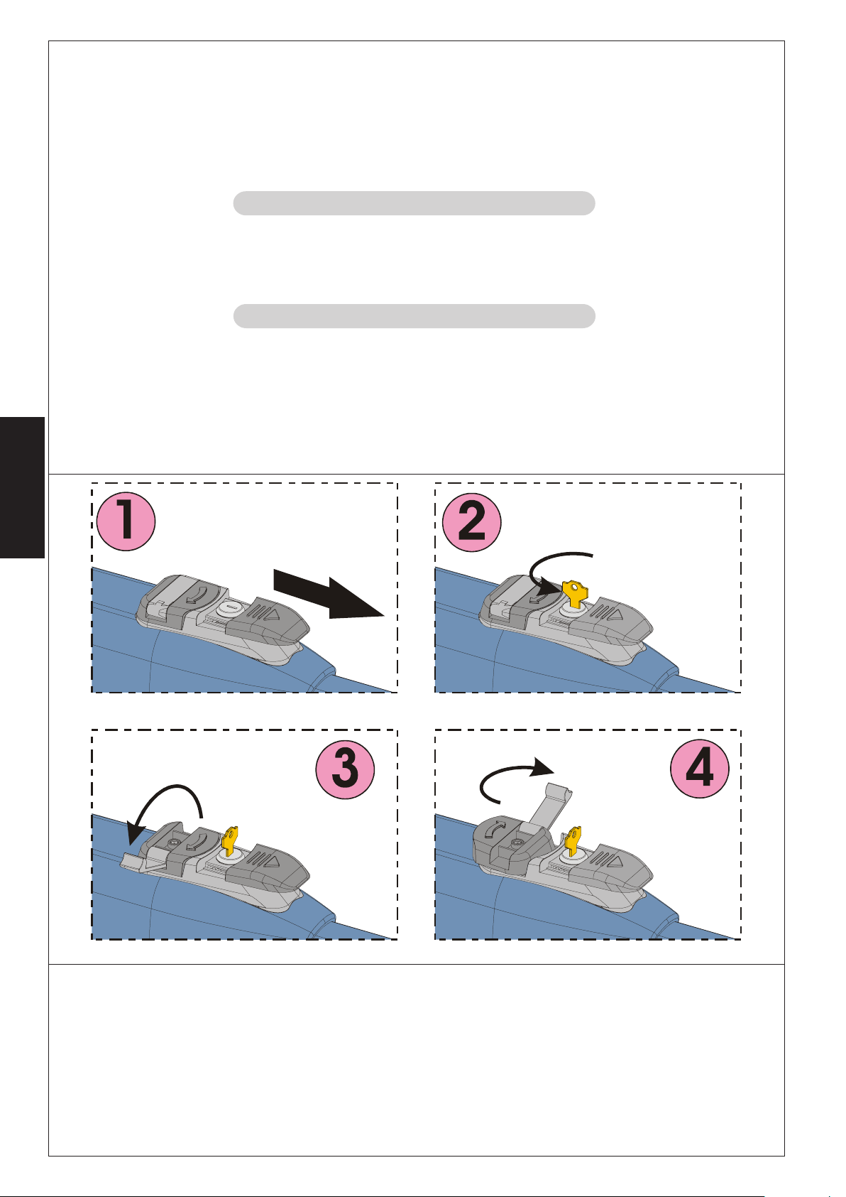
2) Faire coulisser le capuchon de protection, Fig.22/1.
3) Introduire la clé et la tourner de 90°, Fig.22/2.
4) Soulever le levier de manœuvre, Fig.22/3.
5) Pour débloquer l’opérateur tourner de 180° le levier de manœuvre dans la direction de la flèche présente sur le système de
déblocage, Fig.22/4.
6) Effectuer manuellement la manœuvre d’ouverture ou de fermeture du vantail.
FRANÇAIS
Fig. 22
Nota bene: pour maintenir l’opérateur en fonctionnement manuel, il est absolument nécessaire de laisser le dispositif de déblocage
dans la position actuelle et l’installation hors tension.
6.1. Rétablissement du fonctionnement normal
Pour rétablir les conditions de fonctionnement normal, agir comme suit:
1) Tourner le système de déblocage de 180° dans la direction opposée à la flèche.
2) Tourner de 90° la clé de déblocage et l’extraire.
3) Refermer le levier de commande et le couvercle de protection.
4) Alimenter l’installation et effectuer quelques manœuvres pour vérifier le rétablissement de toutes les fonctions de l’automatisme.
26
Page 29

7. ENTRETIEN
Pour assurer dans le temps un fonctionnement correct et un niveau de sécurité constant, effectuer tous les six mois un contrôle
général de l’installation. Dans le livret “Instructions pour l’Utilisateur” se trouve un formulaire pour l’enregistrement des interventions.
8. RÉPARATION
Pour toute réparation éventuelle, s’adresser aux Centres de Réparation agréés.
9. ACCESSOIRES DISPONIBLES
Pour les accessoires disponibles, se reporter au catalogue.
10. APPLICATIONS PARTICULIÈRES
On n’a prévu aucune application différente de celle qui est décrite.
FRANÇAIS
27
Page 30

ÍNDICE
Declaración de conformidad pag.28
Descripción pag.29
Características técnicas pag.30
Instalación pag.30
Prueba de la automación pag.35
Funcionamiento manual pag.35
Mantenimiento pag.36
Reparación pag.36
Accesorios disponibles pag.36
Aplicaciones especiales pag.36
ESPAÑOL
DECLARACIÓN CE DE CONFORMIDAD PARA MÁQUINAS
(DIRECTIVA 98/37/CE)
Fabricante: GENIUS S.p.a.
Dirección: Via Padre Elzi, 32 - 24050 - Grassobbio BERGAMO - ITALIA
Declara que: El operador mod. MISTRAL
• ha sido fabricado para ser incorporado en una máquina o para ser ensamblado con otras maquinarias para constituir una
máquina de conformidad con la Directiva 98/37/CE;
• cumple con los requisitos esenciales de seguridad de las siguientes directivas CEE:
73/23/CEE y sucesiva modificación 93/68/CEE.
89/336/CEE y sucesiva modificación 92/31/CEE y 93/68/CEE
asimismo declara que no está permitido poner en funcionamiento la maquinaria hasta que la máquina en la que deberá
incorporarse o de la cual será un componente haya sido identificada y se haya declarado su conformidad con las condiciones
de la Directiva 98/37/CE.
Grassobbio, 01-06-2005
El Administrador Delegado
D.Gianantoni
28
Page 31

MISTRAL
MISTRAL
Guida per l'utente - User’s guide - Instructions pour l'usager - Guía para el usuario -
Führer für den Benutzer - Gids voor de gebruiker
ITALIANO
Leggere attentamente le istruzioni prima di utilizzare il prodotto e conservarle
per eventuali necessità future
NORME GENERALI DI SICUREZZA
L'automazione MISTRAL, se correttamente installata ed utilizzata, garantisce un
elevato grado di sicurezza.
Alcune semplici norme di comportamento possono evitare inoltre inconvenienti accidentali:
• Non transitare tra le ante quando queste sono in movimento. Prima di transitare
tra le ante, attendere l'apertura completa.
• Non sostare assolutamente tra le ante.
• Non sostare e non permettere a bambini,persone o cose di sostare nelle vici-
nanze dell’automazione.
• Tenere fuori dalla portata dei bambini, radiocomandi o qualsiasi altro datore
d’impulso per evitare che l'automazione possa essere azionata involontariamente.
• Non permettere ai bambini di giocare con l’automazione.
• Non contrastare volontariamente il movimento delle ante.
• Evitare che rami o arbusti possano interferire col movimento delle ante
• Mantenere efficienti e ben visibili i sistemi di segnalazione luminosa.
• Non tentare di azionare manualmente le ante se non dopo averle sbloccate.
• In caso di malfunzionamento, sbloccare le ante per consentire l’accesso ed
attendere l’intervento tecnico di personale qualificato.
• Non eseguire alcuna modifica sui componenti facenti parte il sistema d’auto-
mazione.
• Astenersi da qualsiasi tentativo di riparazione o d’intervento diretto e rivolger-
si solo a personale qualificato.
• Far verificare almeno semestralmente l’efficienza dell’automazione, dei di-
spositivi di sicurezza e del collegamento di terra da personale qualificato.
DESCRIZIONE
L’automazione MISTRAL per cancelli a battente è un operatore elettromeccanico irreversibile che trasmette il movimento all’anta tramite un sistema a vite
senza fine.
L’operatore, disponibile in più versioni, copre tutte le esigenze di installazione. Le
versioni “LS” dispongono di finecorsa in apertura e chiusura.
Il sistema irreversibile garantisce il blocco meccanico dell’anta quando il motore non è in funzione. Un comodo e sicuro sistema di sblocco con chiave personalizzata permette la movimentazione manuale dell’anta in caso di disservizio o di
mancanza di alimentazione.
Fig. 1
Stabilire con il Tecnico installatore la logica di funzionamento che si desidera
impostare per il proprio cancello.
Le ante normalmente si trovano in posizione di chiusura.
Quando la centralina elettronica riceve un comando di apertura tramite il radiocomando o qualsiasi altro datore di impulso, aziona l’apparato elettromeccanico ottenendo la rotazione delle ante, fino alla posizione di apertura che
consente l’accesso.
Per il dettagliato comportamento dell'automazione nelle diverse logiche di funzionamento, fare riferimento al Tecnico installatore.
Nelle automazioni sono presenti dispositivi di sicurezza (fotocellule) che impediscono il movimento delle ante quando un ostacolo si trova nella zona da loro
protetta.
La segnalazione luminosa indica il movimento in atto delle ante.
ATTENZIONE:
• Il corretto funzionamento e le caratteristiche dichiarate si ottengono solo
con accessori e dispositivi di sicurezza GENIUS.
• La mancanza di un dispositivo di frizione meccanica richiede, per garantire
la necessaria sicurezza antischiacciamento, l’impiego di una centrale di
comando con frizione elettronica regolabile.
• L’automazione MISTRAL è stata progettata e costruita per controllare
l’accesso veicolare, evitare qualsiasi altro utilizzo.
FUNZIONAMENTO MANUALE
Nel caso si renda necessario movimentare manualmente l’automazione, per
mancanza di alimentazione o disservizio dell’operatore, agire come di seguito:
1) Togliere l’alimentazione elettrica agendo sull’interruttore differenziale (anche in caso di mancanza di alimentazione).
2) Far scorrere il cappuccio protettivo, Fig.1/1.
3) Inserire la chiave e ruotarla di 90°, Fig.1/2.
4) Sollevare la leva di manovra, Fig.1/3.
5) Per sbloccare l’operatore ruotare di 180° la leva di manovra nella direzione
della freccia presente sul sistema di sblocco, Fig.1/4.
6) Effettuare manualmente la manovra di apertura o di chiusura dell’anta.
Nota bene: Per mantenere l’operatore in funzionamento manuale è
assolutamente necessario lasciare il dispositivo di sblocco nella posizione
attuale e l’impianto disalimentato.
RIPRISTINO DEL FUNZIONAMENTO NORMALE
Per ripristinare le condizioni di funzionamento normale agire come di seguito:
1) Ruotare il sistema di sblocco di 180° nella direzione opposta a quella indicata
dalla freccia.
2) Ruotare di 90° la chiave di sblocco ed estrarla.
3) Richiudere la leva di comando ed il coperchietto di protezione.
1
Page 32

4) Alimentare l’impianto ed eseguire alcune manovre per verificare il corretto
ripristino di tutte le funzioni dell’automazione.
Note: To hold the operator in manual operation the release device should
be left in its current positions and the system should be without power.
Al fine d’assicurare nel tempo un corretto funzionamento ed un costante livello
di sicurezza è opportuno eseguire, con cadenza semestrale, un controllo generale dell’impianto. Nel fascicolo “Guida per l’Utente” è stato predisposto un
modulo per la registrazione degli interventi.
RIPARAZIONE
MANUTENZIONE
Per eventuali riparazioni rivolgersi ai Centri Riparazione autorizzati.
ENGLISH
Read the instructions carefully before using the product and keep them for
future use
GENERAL SAFETY REGULATIONS
If correctly installed and used, MISTRAL automated system ensures a high degree
of safety.
Some simple rules concerning behaviour can prevent accidental trouble:
• Do not pass through the leaves while they are moving. Wait for the leaves to
open fully before passing through.
• Do not, on any account, stand between the leaves.
• Do not stand near the automated system or allow children, persons or things to
stand or lie near there.
• Keep radiocontrols or other pulse generators away from children to prevent
the automated system from being activated involuntary.
• Do not allow children to play with the automated system.
• Do not willingly obstruct leaf movement.
• Prevent any branches or shrubs from interfering with leaf movement
• Keep indicator-lights efficient and easy to see.
• Do not attempt to activate the leaves by hand unless you have released them.
• In the event of a malfunction, release the leaves to allow access and wait for
qualified technical personnel to do the necessary work.
• Do not in any way modify the components of the automated system.
• Do not attempt any kind of repair or direct action whatever and contact
qualified personnel only for the purpose.
• At least every six months: arrange a check by qualified personnel of the
automated system, safety devices and earthing efficiency.
DESCRIPTION
MISTRAL automated system for swing gates is an electro-mechanical non-
reversing operator that transmits motion to the leaf via a worm screw system.
The operator is available in many versions covering therefore every installation
requirement. The “LS” versions are equipped with opening and closing limit
switches.
The non-reversing system ensures the leaf is mechanically locked when the motor
is not operating. A convenient and safe release system with customised key makes
it possible to manually move the leaf in the event of a malfunction or of a power
failure.
Determine with the installation technician the function logic you wish to set for
your gate.
The leaves are usually in closing position.
When the control unit receives an opening command by radiocontrol or from
another pulse generator, it activates the electro-mechanical equipment for the
rotation of the leaves until the opening position enabling the access is reached.
For details on automated system behaviour in different function logics, consult
the installation technician.
Automates systems include safety devices (photocells) that prevent the
movement of the leaves when there is an obstacle in the area they protect.
The light signalling indicates that the leaves are currently moving.
ATTENTION:
• The correct operation and the declared specifications only apply if GENIUS
accessories and safety devices are used.
• As no mechanical clutch is fitted, a control unit with adjustable electronic
clutch is required to ensure the necessary anti-crushing safety.
• MISTRAL automated system was designed and built for controlling vehicle
access. Avoid any other use.
If the automated system needs to be moved manually due to a power lack or to
an operator malfunction, proceed as follows:
1) Cut power by means of the safety circuit breaker (even in the event of a
power lack).
2) Slide the protective cap, Fig.1/1.
3) Insert the key and turn it 90°, Fig.1/2.
4) Lift the control lever, Fig.27/3.
5) To release the operator turn 180° the control lever to the direction indicated
by the arrow on the release system, Fig.1/4.
6) Open and close the leaf manually.
MANUAL OPERATION
RESTORING NORMAL OPERATION
To restore normal operating conditions, proceed as follows:
1) Turn the release system 180° in the opposite direction of the arrow.
2) Turn 90° the release key and remove it.
3) Close the control lever and the protection cover.
4) Power up the system and perform some movements in order to check the
correct restoring of every function of the automated system.
MAINTENANCE
To censure trouble-free operation and a constant safety level, an overall check
of the system should be carried out every 6 months. A form for recording operations
has been included in the “User’s Guide” booklet.
REPAIRS
For any repairs, contact the authorised Repair Centres.
FRANÇAIS
Lire attentivement les instructions avant d’utiliser le produit et le conserver
pour toute nécessité future.
NORMES GENERALES DE SECURITE
S’il est correctement installé et utilisé, l’automatisme MISTRAL garantit un haut
niveau de sécurité.
Par ailleurs, quelques règles simples de comportement peuvent éviter des
problèmes accidentels:
• Ne pas transiter entre les vantaux lorsqu’ils sont en mouvement. Avant de transiter
entre les vantaux, attendre l’ouverture complète.
• Ne jamais stationner entre les vantaux.
• Ne pas stationner et interdire aux enfants et aux tiers de stationner près de
l’automatisme; ne pas y interposer d’objets.
• Eloigner de la portée des enfants les radiocommandes ou tout autre générateur
d’impulsions, pour éviter que l’automatisme ne puisse être actionné
involontairement.
• Interdire aux enfants de jouer avec l’automatisme.
• Ne pas contraster volontairement le mouvement des vantaux.
• Eviter que des branches ou des arbustes n’entravent le mouvement des vantaux.
• Faire en sorte que les systèmes de signalisation lumineuse soient toujours
efficients et bien visibles.
• N’actionner manuellement les vantaux qu’après les avoir débloqués.
• En cas de dysfonctionnement débloquer les vantaux pour permettre l’accès
et attendre l’intervention technique du personnel qualifié.
• N’effectuer aucune modification sur les composants qui font partie du système
d’automation.
• Eviter toute tentative de réparation ou d’intervention directes et s’adresser au
personnel qualifié.
• Faire vérifier, tous les six mois au moins, la fiabilité de l’automatisme, des dispositifs
de sécurité et de mise à la terre par un personnel qualifié.
DESCRIPTION
L’automatisme MISTRAL pour portails battants est un opérateur électromécanique
irréversible qui transmet le mouvement au vantail par l’intermédiaire d’un système
à vis sans fin.
L’opérateur, disponible en plusieurs versions, répond à toutes les exigences
d’installation. Les versions “LS” disposent d’un fin de course en ouverture et
fermeture.
Le système irréversible garantit le verrouillage mécanique du vantail quand le
moteur n’est pas en fonction. Un système pratique et sûr de déblocage à clé
personnalisée permet l’actionnement manuel du vantail en cas de
dysfonctionnement ou de coupure de courant.
Déterminer avec l’Installateur la logique de fonctionnement qu’on souhaite
sélectionner pour le portail.
Les vantaux se trouvent normalement en position de fermeture.
Quand la centrale électronique reçoit une commande d’ouverture par
l’intermédiaire de la radiocommande ou par tout autre générateur d’impulsions,
actionne l’appareil électromécanique en obtenant la rotation des vantaux,
jusqu’à la position d’ouverture qui permet l’accès.
Consulter l’Installateur pour le comportement détaillé de l’automatisme dans les
différentes logiques de fonctionnement.
Les automatismes sont dotés de systèmes de sécurité (photocellules) qui
empêchent le mouvement des vantaux quand un obstacle se trouve dans la
zone qu’ils protègent.
La signalisation lumineuse indique que les vantaux sont en mouvement.
ATTENTION:
• Le fonctionnement correct et les caractéristiques déclarées ne sont
possibles qu’avec les accessoires et les dispositifs de sécurité GENIUS.
• L’absence d’un dispositif d’embrayage mécanique exige, pour garantir la
sécurité anti-écrasement, une centrale de commande à embrayage
électronique réglable.
• L’automatisme MISTRAL a été conçu et construit pour contrôler l’accès
des véhicules; éviter toute autre utilisation.
2
Page 33

ALLEGATO 1 : PIANO MANUTENZIONE PROGRAMMATA - ENCLOSURE 1 : PROGRAMMED MAINTENANCE SCHEDULE
ANNEXE 1 : PLAN D’ENTRETIEN PROGRAMMÉ - ANEXO 1 : PLAN DE MANTENIMIENTO PROGRAMADO
ANLAGE 1 : PLAN DER PROGRAMMIERTEN WARTUNGSARBEITEN - BIJLAGE 1 – SCHEMA GEPROGRAMMEERD ONDERHOUD
ILARTSEMESILLORTNOC
SKCEHCYLHTNOM-XIS
SLEIRTSEMESSELORTNOC
SELARTSEMESSELORTNOC
NEGNUFÜRPEHCILRHÄJBLAH
SELORTNOCESKJILRAAJFLAH
aicaciffedeotnemagelloC
elaiznereffiderotturretni'lled
foycneiciffednanoitcennoC
rekaerbtiucricytefas
edé
ticaciffetenoixennoC
leitneréffidruetpurretni'l
laicnerefid
oitknuFdnussulhcsnA
tiekgithcütsn
sretlahcslaitnereffiDsed
ednavgnikrewnegnidnibreV
raalekahcsleeitnereffid
ufotterrocearutaraT
otnemanoizn
acinortteleenoizirfalled
fonoitarepotcerrocdnagnitteS
hctulccinortcele
teegannolatE
tnemennoitcnof
egayarbme'ledtcerroc
euqinortcelé
otneimanoicnufotcerrocyodaraT
ocinórtceleeugarbmeled
thcütsnoitknuFdnugnulletsniE
gnulppuKnehcsinortkelered
navgnikrewetcerrocnegnilletsfA
keleed
gnileppokehcsinort
azzerucisidivitisopsid
fonoitarepodnasnoitcennoC
secivedytefas
mennoitcnoftesnoixennoC
étirucésedsfitisopsid
edotneimanoicnufysenoixenoC
dadirugesedsovitisopsidsol
githcütsnoitknuFdnuessülhcsnA
negnuthcirrovstiehrehciSred
ednavgnikrewnenegnitiulsnaA
giliev
negnineizroovsdieh
alledaicaciffedeotnemagelloC
arretidaserp
tekcos
tenoixennoC
esirpaledéticaciffe
erreted
arreit
tiekgithcütsnoitknuFdnussulhcsnA
gnudrEred
rewnegnitiulsnaA
ednavgnik
gnidraa
idovitisopsidledotnemanoiznuF
elaunamoccolbs
esaelerlaunamfonoitarepO
ecived
edfit
isopsidudtnemennoitcnoF
leunamegacolbéd
edovitisopsidledotneimanoicnuF
launamoeuqolbsed
ithcütsnoitknuF
nelleunamredtiekg
gnuthcirrovebagierF
edneidebdnahtehnavgnikreW
meetsyslednergtno
°1
°2
____/___/___
°3
____/___/___
°4
____/___/___
°5
____/___/___
°6
____/___/___
°7
____/___/___
°8
____/___/___
°9
____/___/___
____/___/___
rotpurretniledaicacifeynóixenoC
tiekgi
iedotnemanoiznufeitnemagelloC
sedtne
tiek
htraefoycneiciffednanoitcennoC
edamotaledaicacifeynóixenoC
°01
____/___/___
Page 34

ILARTSEMESILLORTNOC
SKCEHCYLHTNOM-XIS
°1
°2
°3
°4
°5
°6
°7
°8
°9
°01
SLEIRTSEMESSELORTNOC
SELARTSEMESSELORTNOC
NEGNUFÜRPEHCILRHÄJBLAH
SELORTNOCESKJILRAAJFLAH
____/___/___
____/___/___
____/___/___
____/___/___
____/___/___
____/___/___
____/___/___
____/___/___
____/___/___
____/___/___
ilautneveilgedotnemanoiznuF
asrocenif
)ynafi(sehctiwstimilfonoitarepO
esruocedsnifsedtnemennoitcnoF
sleut
nevé
selautnevesoledotneimanoicnuF
arerracedselanif
nelleutneveredtiekgithcütsnoitknuF
retlahcsdnE
eleutne
veednavgnikreW
sraalekahcsdnie
otnemanoiznufeotnemagelloC
irosseccailged
fonoitarepodnanoitcennoC
seirosse
cca
sedtnemennoitcnoftenoixennoC
seriossecca
soledotneimanoicnufynóixenoC
soirosecca
nussulhcsnA
tiekgithcütsnoitknuFd
sröhebuZsed
ednavgnikrewnegnitiulsnaA
seriossecca
erottudirotomledoiggassiF
omraeG
noitidnocgnixifrot
ruetcudérotomudnoitaxiF
rotcuderrotomlednóicajiF
sebeirteGsedgnugitsefeB
ednavgnigitseveB
vrotom
gnigartre
oiggassifidinrepiedinoizidnoC
snoitidnocsnipgninetsaF
noitaxifedsexasedsnoitidnoC
oicidnoC
edsonrepsoledsen
nóicajif
etfitssgnugitsefeBreddnatsuZ
ednaveitidnoC
nennepsgnigitseveb
sU
/eroiretsopoccatta'lledaru
eroiretna
gnittiftnorf/raerforaeW
ehcatta'dettapalederusU
erueirétna/erueirétsop
sagseD
/roiretsopemlapmeledet
roiretna
sessulhcsnAsedßielhcsreV
enrov/netnih
etsroov/etsrethcaednavegatjilS
gnigitseveb
dilareneginoizidnoC
ollecnacle
snoitidnoclarenegetaG
liatropudselarénégsnoitidnoC
aledselarenegsenoicidnoC
alecnac
sr
oTseddnatsuZreniemegllA
troopednaveitidnocenemeglA
Page 35

note - notes - note - notas - anmerkung - opmerkingen
Page 36

note - notes - note - notas - anmerkung - opmerkingen
Page 37

Si nécessaire, actionner manuellement l’automatisme; en cas de coupure de
courant ou de dysfonctionnement de l’opérateur, agir comme suit:
1) Couper le courant en agissant sur l’interrupteur différentiel (même si le courant
est déjà coupé).
2) Faire coulisser le capuchon de protection, Fig.1/1.
3) Introduire la clé et la tourner de 90°, Fig.1/2.
4) Soulever le levier de manœuvre, Fig.1/3.
5) Pour débloquer l’opérateur tourner de 180° le levier de manœuvre dans la
direction de la flèche présente sur le système de déblocage, Fig.1/4.
6) Effectuer manuellement la manœuvre d’ouverture ou de fermeture du vantail.
Nota bene: pour maintenir l’opérateur en fonctionnement manuel, il est
absolument nécessaire de laisser le dispositif de déblocage dans la position
actuelle et l’installation hors tension.
RÉTABLISSEMENT DU FONCTIONNEMENT NORMAL
FONCTIONNEMENT MANUEL
Pour rétablir les conditions de fonctionnement normal, agir comme suit:
1) Tourner le système de déblocage de 180° dans la direction opposée à la
flèche.
2) Tourner de 90° la clé de déblocage et l’extraire.
3) Refermer le levier de commande et le couvercle de protection.
4) Alimenter l’installation et effectuer quelques manœuvres pour vérifier le
rétablissement de toutes les fonctions de l’automatisme.
ENTRETIEN
Pour assurer dans le temps un fonctionnement correct et un niveau de sécurité
constant, effectuer tous les six mois un contrôle général de l’installation. Dans le
livret “Instructions pour l’Utilisateur” se trouve un formulaire pour l’enregistrement
des interventions.
RÉPARATION
Pour toute réparation éventuelle, s’adresser aux Centres de Réparation agréés.
ESPAÑOL
Lea detenidamente las instrucciones antes de utilizar el producto y
consérvelas para posibles usos futuros.
NORMAS GENERALES DE SEGURIDAD
La automación MISTRAL, si se instala y utiliza correctamente, garantiza un elevado
grado de seguridad.
Algunas simples normas de comportamiento pueden evitar inconvenientes o
accidentes:
• No transite entre las hojas cuando las mismas están en movimiento. Antes de
transitar entre las hojas espere su completa apertura.
• No se detenga absolutamente entre las hojas.
• No se detenga y no permita que niños, personas u objetos estén detenidos
cerca de la automación.
• Mantenga fuera del alcance de los niños mandos remotos o cualquier otro
generador de impulsos para evitar que la automación pueda accionarse
involuntariamente.
• No permita que los niños jueguen con la automación.
• No obstaculice voluntariamente el movimiento de las hojas.
• Evite que ramas o arbustos interfieran con el movimiento de las hojas.
• Mantenga en buen estado y bien visibles los sistemas de señalización luminosa.
• No intente accionar manualmente las hojas si no están desbloqueadas.
• En caso de mal funcionamiento, desbloquee las hojas para permitir el acceso
y espere a que personal técnico cualificado intervenga para solucionar el
problema.
• No efectúe ninguna modificación en los componentes que formen parte del
sistema de automación.
• Absténgase de intentar reparar o de intervenir directamente, diríjase
exclusivamente a personal cualificado.
• Haga verificar por lo menos semestralmente el funcionamiento de la
automación, de los dispositivos de seguridad y la conexión a tierra por personal cualificado.
DESCRIPCIÓN
La automación MISTRAL para cancelas de batientes es un operador
electromecánico irreversible que transmite el movimiento a la hoja por medio
de un sistema de tornillo sin fin.
El operador, disponible en varias versiones, cubre todas las exigencias de
instalación. Las versiones “LS” disponen de final de carrera en apertura y cierre.
El sistema irreversible garantiza el bloqueo mecánico de la hoja cuando el motor
no está en funcionamiento. Un cómodo y seguro sistema de desbloqueo con
llave personalizada permite maniobrar manualmente la hoja en caso de falta
de alimentación eléctrica o de avería.
Establezca con el Técnico instalador la lógica de funcionamiento que se desea
programar para la cancela.
Las hojas normalmente están en posición de cierre.
Cuando la centralita electrónica recibe un mando de apertura mediante el
radiomando o cualquier otro generador de impulso, acciona el aparato
electromecánico obteniendo así la rotación de las hojas, hasta la posición de
apertura que permite el acceso.
Para conocer en detalle el comportamiento de la automación en las diferentes
lógicas de funcionamiento, consulte al Técnico instalador.
Las automaciones están equipadas con dispositivos de seguridad (fotocélulas)
que impiden el movimiento de las hojas cuando un obstáculo se encuentra en la
zona protegida por dichos dispositivos.
La señalización luminosa indica el movimiento en acto de las hojas.
ATENCIÓN:
• El correcto funcionamiento y las características declaradas sólo se obtienen
con los accesorios y dispositivos de seguridad GENIUS.
• Si falta un dispositivo de embrague mecánico es necesario, a fin de
garantizar la seguridad antiaplastamiento, utilizar una central de mando
con embrague electrónico regulable.
• La automación MISTRAL ha sido proyectada y fabricada para controlar el
acceso de vehículos, evítese cualquier otra utilización.
FUNCIONAMIENTO MANUAL
Si fuera necesario mover la automación a mano, por ejemplo por un corte de
corriente o un fallo del operador, proceda del siguiente modo:
1) Quite la alimentación eléctrica por medio del interruptor diferencial
(también en caso de corte de corriente).
2) Deslice el capuchón de protección, Fig.1/1.
3) Introduzca la llave y gírela 90°, Fig.1/2.
4) Levante la palanca de maniobra, Fig.1/3.
5) Para desbloquear el operador, gire 180° la palanca de manivela en la
dirección indicada por la flecha presente en el sistema de desbloqueo, Fig.1/
4.
6) Efectúe la maniobra de apertura o cierre de la hoja.
Nota: Para mantener el operador en funcionamiento manual es
absolutamente necesario dejar el dispositivo de desbloqueo en la posición
actual y el equipo sin alimentación.
RESTABLECIMIENTO DEL FUNCIONAMIENTO NORMAL
Para restablecer las condiciones de funcionamiento normal proceda del
siguiente modo:
1) Gire el sistema de desbloqueo 180° en la dirección opuesta a la indicada por
la flecha.
2) Gire 90° la llave de desbloqueo y quítela.
3) Cierre de nuevo la palanca de mando y la tapa de protección.
4) Alimente el equipo y realice algunas maniobras para comprobar que todas
las funciones de la automación se han restablecido correctamente.
MANTENIMIENTO
Para asegurar un correcto funcionamiento a lo largo del tiempo y un constante
nivel de seguridad es conveniente realizar, con periodicidad semestral, un control
general del equipo. En el fascículo “Guía para el Usuario” se ha preparado un
módulo para anotar las intervenciones.
REPARACIÓN
Para eventuales reparaciones diríjase a los Centros de Reparación autorizados.
DEUTSCH
Die nachfolgenden Anleitungen sollten aufmerksam gelesen werden, bevor
das Produkt eingesetzt wird, und für eine eventuelle zukünftige Bezugnahme
aufbewahrt werden
ALLGEMEINE SICHERHEITSVORSCHRIFTEN
Die Automation MISTRAL gewährleistet bei korrekter Installation und
bestimmungsgemäßem Gebrauch ein hohes Sicherheitsniveau.
Einige einfache Verhaltensregeln können darüber hinaus zur Vermeidung von
Unfällen sinnvoll sein:
• Der Durchgang zwischen den Flügeln ist untersagt, solange diese sich in
Bewegung befinden. Vor dem Passieren der Flügel sollte die vollständige Öffnung
abgewartet werden.
• Der Aufenthalt zwischen den Flügeln ist strikt untersagt.
• Der Aufenthalt von Kindern oder Erwachsenen oder das Abstellen von
Gegenständen in der unmittelbaren Nähe der Automation sollten
unterbleiben. Dies gilt umso mehr während des Betriebs.
• Funksteuerungen oder andere Impulsgeber, mit denen die Automation
versehentlich gestartet werden könnte, sollten Kindern unzugänglich
aufbewahrt werden.
• Die Automation ist kein Spielzeug.
• Die Bewegung der Flügel sollte nicht absichtlich entgegen gewirkt werden.
• Das Vorhandensein von Ästen oder Büschen, die sich im Bewegungsradius der
Flügel befinden, sollte vermieden werden.
• Die Systeme der Leuchtanzeige sollten stets funktionsfähig und gut sichtbar
sein.
• Die Flügel sollten erst dann manuell bewegt werden, nachdem die Entriegelung
vorgenommen wurde.
• Im Falle von Betriebsstörungen sind die Flügel zu entriegeln, um die Zufahrt zu
ermöglichen und der technische Einsatz von qualifiziertem Fachpersonal
abzuwarten.
• Auf den Teilen, die zum Automationssystem gehören, dürfen keinerlei
Veränderungen ausgeführt werden.
• Reparaturen oder andere direkte Eingriffe sollten unterbleiben, bzw. lediglich
durch qualifiziertes Fachpersonal vorgenommen werden.
3
Page 38

• Mindestens einmal halbjährlich die Betriebsfähigkeit der Automation, der
Sicherheitsvorrichtungen und der Erdung durch qualifiziertes Fachpersonal
prüfen lassen.
BESCHREIBUNG
Die Automation MISTRAL für Flügeltore ist ein irreversibler elektromechanischer
Antrieb, der über ein Schneckensystem die Bewegung auf den Flügel überträgt.
Der Antrieb ist in mehreren Ausführungen für alle Einbaubedürfnisse erhältlich.
Die Ausführungen “LS” verfügen über Endschalter beim Öffnen und beim
Schließen.
Das irreversible System gewährleistet die mechanische Verriegelung des Flügels,
wenn der Motor nicht in Betrieb ist. Ein praktisches und sicheres Freigabesystem
mit individuellem Schlüssel ermöglicht die manuelle Bewegung des Flügels bei
Betriebsstörungen oder Stromausfall.
Mit dem Installateur ist die für das Tor gewünschte Betriebslogik zu bestimmen.
Die Flügel befinden sich normalerweise in Schließstellung.
Empfängt die elektronische Steuereinheit einen Öffnungsimpuls über die
Funksteuerung oder jede andere Impulsgeber, wird das elektromechanische
System für die Bewegung der Flügel eingeschaltet, bis die Öffnungsposition
erreicht ist, die den Zugang erlaubt.
Hinsichtlich des genauen Verhaltens der Automation in den verschiedenen
Betriebslogiken ist auf den Installateur Bezug zu nehmen.
Auf den Automationen befinden sich Sicherheitsvorrichtungen (Photozellen), die
die Bewegung der Flügel verhindern, soweit sicht ein Hindernis im von ihnen
überwachten Bereich befindet.
Die Leuchtsignale zeigen die jeweils ablaufende Bewegung der Flügel.
ACHTUNG:
• Der ordnungsgemäße Betrieb und die erklärten Daten werden nur mit
Zubehör und Sicherheitsvorrichtungen der Marke GENIUS erreicht.
• Das Fehlen einer mechanischen Kupplungsvorrichtung erfordert zur
Gewährleistung des erforderlichen Quetschschutzes den Einsatz eines
Steuergeräts mit einstellbarer elektronischen Kupplung.
• Die Automation MISTRAL wurde für die Zufahrtskontrolle von Fahrzeugen
entwickelt und hergestellt, andere Anwendungen sind zu vermeiden.
MANUELLER BETRIEB
Sollte die manuelle Bewegung der Automation erforderlich sein aufgrund von
Stromausfall oder Betriebsstörungen des Antriebs, sind die nachfolgenden Schritte
auszuführen:
1) Mit Hilfe des Differentialschalters (auch bei Stromausfall) die Stromversorgung
unterbrechen.
2) Die Schutzhaube – Abb. 27/1 – gleiten lassen.
3) Den Schlüssel einstecken und um 90° drehen, Abb.27/2.
4) Den Bedienhebel heben, Abb. 27/3
5) Zur Freigabe des Antriebs den Bedienhebel um 180° in Richtung des auf dem
Freigabesystem angegebenen Pfeils drehen, Abb. 27/4.
6) Den Vorgang zum Öffnen oder Schließen des Flügels manuell ausführen.
Anmerkung: Zur Beibehaltung des manuellen Betriebs des Antriebs muss die
Freigabevorrichtung unbedingt in ihrer aktuellen Position gelassen werden
und die Stromzufuhr zur Anlage muss weiterhin unterbrochen bleiben.
WIEDERHERSTELLUNG DES NORMALBETRIEBS
Zur Wiederherstellung der normalen Betriebsbedingungen sind die
nachfolgenden Schritte auszuführen:
1) Das Freigabesystem um 180° in die entgegen gesetzte Richtung des Pfeils
drehen.
2) Den Freigabeschlüssel um 90° drehen und herausziehen.
3) Den Bedienhebel und den Schutzdeckel verschließen.
4) Die Anlage mit Strom versorgen und einige Vorgänge ausführen, um die
korrekte Wiederherstellung aller Funktionen der Automation zu prüfen.
WARTUNG
Damit langfristig eine ordnungsgemäße Betriebsweise und ein konstantes
Sicherheitsniveau gewährleistet werden, ist im Abstand von 6 Monaten eine
allgemeine Kontrolle der Anlage vorzunehmen. Im Heft „Anweisungen für den
Benutzer” ist ein Formular für die Aufzeichnung der Arbeiten enthalten.
REPARATUR
Eventuelle Reparaturen sind von einem Vertrags-Center auszuführen.
• Blijf beslist niet stilstaan tussen de vleugels.
• Sta het niet toe dat kinderen, volwassenen of voorwerpen zich in de buurt van
het automatische systeem bevinden.
• Houd de radio-afstandsbediening en alle andere impulsgevers buiten het
bereik van kinderen, om te voorkomen dat het automatische systeem
onopzettelijk kan worden bediend.
• Sta het kinderen niet toe met het automatische systeem te spelen.
• Houd de beweging van de vleugels niet opzettelijk tegen.
• Voorkom dat takken of struiken de beweging van de vleugels kunnen hinderen.
• Houd de lichtsignaleringssystemen in goede staat van werking en goed
zichtbaar.
• Probeer de vleugels niet met de hand te bewegen als ze niet eerst ontgrendeld
zijn.
• Bij storingen moeten de vleugels worden ontgrendeld om binnen te kunnen en
moet een technische ingreep door gekwalificeerd personeel worden
afgewacht.
• Voer geen wijzigingen uit op componenten die deel uitmaken van het
automatische systeem.
• Doe geen pogingen tot reparatie of andere directe ingrepen, en wendt u
zich uitsluitend tot gekwalificeerd personeel.
• Laat de werking van het automatische systeem, de veiligheidsvoorzieningen
en de aarding minstens eenmaal per half jaar controleren door
gekwalificeerd personeel.
BESCHRIJVING
Het automatische systeem MISTRAL voor poorten met draaiende vleugels is een
onomkeerbare elektromechanische aandrijving die de beweging op de vleugel
overdraagt via een wormschroefsysteem.
De aandrijving is leverbaar in verschillende uitvoeringen, zodat aan alle
installatie-eisen kan worden voldaan. De uitvoeringen “LS” hebben
eindschakelaars bij opening en sluiting.
Het onomkeerbare systeem garandeert mechanische vergrendeling van de
vleugel wanneer de motor niet in werking is. Een praktisch, veilig
ontgrendelsysteem met individuele sleutel maakt handmatige verplaatsing van
de vleugel mogelijk als het systeem niet goed werkt of als de stroom is uitgevallen.
Bepaal samen met de installatiemonteur volgens welke bedrijfslogica u uw poort
wenst te installeren.
De vleugels bevinden zich gewoonlijk in gesloten positie.
Wanneer de elektronische unit een commando tot opening ontvangt via de
radio-afstandsbediening of een willekeurige andere impulsgever, drijft hij het
elektromechanische apparaat aan dat de vleugels in geopende positie draait,
waardoor toegang mogelijk wordt.
Voor bijzonderheden over het gedrag van het automatische systeem in de
verschillende bedrijfslogica’s, vraag de installatietechnicus.
Op de automatische systemen zijn veiligheidsvoorzieningen (fotocellen)
aanwezig die de beweging van de vleugels verhinderen wanneer er zich een
obstakel in het door hun beschermde gebied bevindt.
De lamp geeft aan dat de vleugels in beweging zijn.
LET OP:
• Het systeem kan alleen correct werken en heeft alleen de verklaarde
eigenschappen als er GENIUS accessoires en veiligheidsvoorzieningen
worden gebruikt.
• Aangezien er geen mechanische koppeling aanwezig is, dient er een
bedieningsunit met regelbare elektronische koppeling te worden gebruikt
om de nodige beveiliging tegen inklemming te garanderen.
• Het automatische systeem MISTRAL is ontworpen en gebouwd voor controle
op de toegang door voertuigen. Het mag niet voor andere doeleinden
worden gebruikt.
HANDBEDIENDE WERKING
In het geval dat het automatische systeem met de hand moet worden verplaatst,
doordat de stroom is uitgevallen of doordat de aandrijving niet goed werkt,
dient u als volgt te handelen:
1) Neem de elektrische voeding weg via de differentieelschakelaar (ook als
de stroom is uitgevallen).
2) Schuif het beschermdeksel weg, fig. 1/1.
3) Steek de sleutel erin en draai hem 90°, fig. 1/ 2.
4) Til de bedieningshendel op, fig. 1/ 3.
5) Om de aandrijving te ontgrendelen draait u de bedieningshendel 180° in de
richting van de pijl op het ontgrendelsysteem, fig. 1/ 4.
6)Voer de manoeuvre voor opening of sluiting van de vleugel met de hand uit.
Nota bene: om de aandrijving op handbediening te houden moet het
ontgrendelsysteem beslist in de actuele positie blijven, en mag de installatie
niet elektrisch worden gevoed.
NEDERLANDS
Lees deze instructies aandachtig door alvorens het product te gebruiken,
en bewaar hen voor eventueel gebruik in de toekomst
ALGEMENE VEILIGHEIDSVOORSCHRIFTEN
Als het automatische systeem MISTRAL correct geïnstalleerd en gebruikt wordt,
garandeert het een hoge veiligheidsgraad.
Verder kunnen door enkele eenvoudige gedragregels ongewenste storingen
worden voorkomen:
• Passeer niet tussen de vleugels wanneer deze in beweging zijn. Wacht tot de
vleugels helemaal geopend zijn, alvorens te passeren.
Ga als volgt te werk om de normale werking te hervatten:
1) Draai het ontgrendelsysteem 180° tegen de richting van de pijl in.
2) Draai de ontgrendelsleutel 90° om en haal hem weg.
3) Sluit de bedieningshendel en het beschermdeksel.
4) Geef de installatie voeding en voer een paar manoeuvres uit, om na te gaan
of alle functies van het automatische systeem correct zijn hersteld.
ONDERHOUD
HERSTEL VAN DE NORMALE WERKING
Om te verzekeren dat het apparaat goed blijft functioneren en voldoende veilig
is, is het wenselijk elke zes maanden een algemene controle van de installatie te
laten uitvoeren. In het boekje “Handleiding voor de gebruiker” is een formulier
te vinden waarop de ingrepen kunnen worden geregistreerd.
REPARATIE
Voor eventuele reparaties dient u contact op te nemen met erkende
reparatiecentra.
4
Page 39

AUTOMACIÓN MISTRAL
2. DESCRIPCIÓN
La automación MISTRAL para cancelas de batientes es un operador electromecánico irreversible que transmite el movimiento a
la hoja por medio de un sistema de tornillo sin fin.
El operador, disponible en varias versiones, cubre todas las exigencias de instalación. Las versiones “LS” disponen de final de carrera
en apertura y cierre.
El sistema irreversible garantiza el bloqueo mecánico de la hoja cuando el motor no está en funcionamiento. Un cómodo y seguro
sistema de desbloqueo con llave personalizada permite maniobrar manualmente la hoja en caso de falta de alimentación
eléctrica o de avería.
ATENCIÓN:
• El correcto funcionamiento y las características declaradas sólo se obtienen con los accesorios y dispositivos de seguridad
GENIUS.
• Si falta un dispositivo de embrague mecánico es necesario, a fin de garantizar la seguridad antiaplastamiento, utilizar una
central de mando con embrague electrónico regulable.
• La automación MISTRAL ha sido proyectada y fabricada para controlar el acceso de vehículos, evítese cualquier otra utilización.
.soP nóicpircseD .soP nóicpircseD
1rotcuderrotoM5roiretsopadirB
2oeuqolbsededovitisopsiD6roiretsopemlapmE
3ogatsáV7roiretsopemlapmeonre
4roiretnaadirB8senrobedatelgerapaT
P
3
2
5
2.1. Dimensiones
155
1
4
7
ESPAÑOL
6
8
Fig. 1
100
840 (MISTRAL 300)
935 (MISTRAL 400)
Fig. 2
29
Page 40
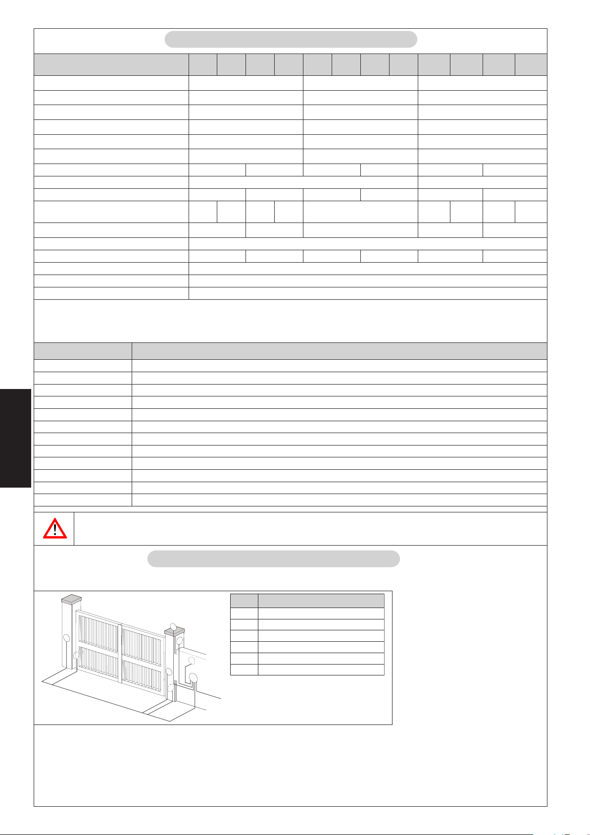
4
3. CARACTERÍSTICAS TÉCNICAS
SACINCÉTSACITSÍRETCARAC 003
003
SL
004
004
SL
423
423
SL
424
424
SL
423
-V511-
nóicatnemilA~V032cdV42~V511
)W(aicnetoP00307003
)A(etneirroC3.13 5.2
)C°(nóiccetorpomreT041- 041
dnoC8-52
)Fµ(rodasne
)Nad(ejupmE003082003
)mm(arerraC003004003004003004
)ges/mc(ogatsávadilasdadicoleV 6,158.1
)m(.xámajoH3
°02anóicazilituedaicneucerfyopiT
C
iC03~52~57~03~52~
C°02asovitacidniarohsolc
)1(
3S
3S
%03
%53
)2(
4
3S
3S
%03
%53
)1(
3
%001
)2(
4
)1(
3
3S
%03
)C°(etneibmaarutarepmeT 55+02-
)gK(rodarepooseP8.788.78 8.78
)mm(rodarepodutignoL 2.gifesaév
reposenoisnemiD 2.gifesaév
)mm(roda
nóiccetorpedodarG 44PI
(1)
Con hojas de más de 2.5 m es obligatorio instalar la electrocerradura para garantizar el bloqueo de la hoja
(2)
Con hojas de más de 3 m es obligatorio instalar la electrocerradura para garantizar el bloqueo de la hoja
3.1. Versiones
OLEDOM NÓISREV
003LARTSIM~V032elbisreverrirotcuderrotoM
SL003LARTSIM erreic/arutrepanearerracedlanifnocy~V032elb
004LARTSIM~V032elbisreverrirotcuderrotoM
SL004LARTSIM erreic/arutrepanearerracedla
423LARTSIMcdV42elbisreverrirotcuderrotoM
SL423LARTSIM erreic/arutre
424LARTSIMcdV42elbisreverrirotcuderrotoM
IM erreic/arutrepanearerracedlanifnocycdV42elbisreverrirotcuderrotoM
SL424LARTS
ESPAÑOL
04LARTSIM~V511elbisreverrirotcuderrotoM
~V511-003LARTSIM~V511elbisreverriro
tcuderrotoM
~V511-SL003LARTSIM erreic/arutrepanearerracedlanifnocy~V511elbisreverrirotcuderrotoM
~V511-0
~V511-SL004LARTSIM erreic/arutrepanearerracedlanifnocy~V511elbis
isreverrirotcuderrotoM
nifnocy~V032elbisreverrirotcuderrotoM
panearerracedlanifnocycdV42elbisreverrirotcuderrotoM
reverrirotcuderrotoM
SL423
424
-V511-
-V511-
4
3S
%53
3S
%03
SL424
-V511-
)2(
3S
%53
En el caso de operadores homologados CSA-UL, para mantener la homologación, es necesario utilizar la central 455
MPS UL 115.
4. INSTALACIÓN
4.1. Predisposiciones eléctricas (equipo estándar)
.soP nóicpircseD
1serodarepO
6
1
Tx
2
2
m
2
m
m
,5
1
m
x
,5
0
x
2
4x1,5 mm
2
m
m
,5
1
2
x
2
1
x
R
2
2
2
m
3x0,5 m
5
2
4
m
m
m
m
,5
,5
0
0
x
3
3
x
2
3
x1
,5
m
230 V~
2salulécotoF
3ocinórtceleopiuqE
4evalledrodasluP
5arotpeceR
6etnalletseD
2
m
Notas:
• Para tender los cables eléctricos,
utilice tubos rígidos y/o flexibles
adecuados.
• Para evitar cualquier interferencia
se aconseja separar siempre los
cables de conexión de los
accesorios a baja tensión y de
mando de los cables de
alimentación a 230/115 V~
utilizando vainas separadas.
Fig. 3
30
Page 41

4.2. Comprobaciones previas
Para que la automación funcione correctamente, la estructura de la cancela existente, o la que se tiene que realizar, tiene que
presentar las siguientes características:
• Los elementos constructivos mecánicos deben estar de acuerdo con lo establecido en las Normas EN 12604 y EN 12605.
• Longitud de la hoja conforme con las características del operador.
• Estructura de las hojas robusta y rígida, adecuada para la automación.
• Movimiento regular y uniforme de las hojas, sin rozamientos ni tropiezos durante toda la carrera de apertura.
• Buen estado y adecuada robustez de las bisagras.
• Presencia de los topes mecánicos de final de carrera tanto en apertura como en cierre
• Presencia de una eficiente toma de tierra para la conexión eléctrica del operador.
Se aconseja efectuar las posibles intervenciones de fábrica antes de instalar la automación.
El estado de la estructura de la cancela influye directamente en la fiabilidad y seguridad de la automación.
4.3. Cotas de instalación
Establezca la posición de montaje del operador tomando como
referencia la Fig.4.
Compruebe atentamente que la distancia entre la hoja abierta
y los posibles obstáculos (paredes, vallas, etc.) sea superior al
espacio ocupado por el operador.
D
A
Z
B
E
L
a
(1)
carrera útil del operador
oledoM
V511-003/423/003LARTSIM
V511-004/424/004LARTSIM
(2)
cota máxima
α
°0954154109258060111
°01102153159206060111
°09591591093521070921
°01107107
A B C
1093011060921
(3)
cota mínima
4.3.1. Reglas generales para establecer las cotas de instalación
• Para obtener aperturas de la hoja a 90° : A+B=C
• Para obtener aperturas de la hoja superiores a 90° : A+B<C
• cotas A y B más bajas determinan velocidades periféricas de la hoja más elevadas.
• limite la diferencia entre la cota A y la cota B a 4 cm: una diferencia superior
origina variaciones elevadas de la velocidad durante el movimiento de apertura
y cierre de la cancela.
• mantenga una cota Z de modo tal que el operador no choque contra el pilar.
• con las versiones LS los finales de carrera intervienen en los primeros y últimos 30
mm. Por consiguiente las cotas A y B deben ser tales que permitan aprovechar
toda la carrera del operador. Carreras menores podrían limitar o incluso anular
el campo de regulación de los finales de carrera.
Si las dimensiones del pilar o la posición de la bisagra no permiten instalar el operador,
para mantener la cota A establecida es necesario realizar un hueco en el pilar, tal
y como se indica en la Fig.5.5. El hueco ha de tener unas dimensiones tales que
permitan una fácil instalación, la rotación del operador y el accionamiento del
dispositivo de desbloqueo.
Fig. 4
)1(
)2(
D
)3(
Z
L E
)3(
54
54
ESPAÑOL
31
Fig. 5
Page 42

4.4. Instalación de los operadores
1) Fije la brida posterior en la posición establecida con anterioridad. En caso de que el pilar fuera de hierro, suelde atentamente
la brida directamente en el pilar (Fig.6). Si el pilar es de obra, utilice la correspondiente placa (opcional) para la fijación
mediante atornillado (Fig.7) utilizando adecuados sistemas de fijación. Seguidamente suelde la brida a la placa.
Durante las operaciones de fijación compruebe con un nivel de burbuja que la brida esté perfectamente horizontal.
Fig. 6
2) Ensamble el empalme posterior al operador como se indica en la Fig.8.
ESPAÑOL
3) Prepare el operador para el funcionamiento manual (véase párrafo 6)
4) Extraiga completamente el vástago hasta el tope, fig.9 ref.1.
5) Bloquee de nuevo el operador (véase párrafo 6.1 )
6) Gire media vuelta o una vuelta el vástago en sentido horario, Fig.9 ref.2
7) Ensamble la brida anterior como se indica en la Fig.10.
Fig. 7
Fig. 8
1
2
Fig. 9
8) Fije el operador a la brida posterior por medio de los pernos suministrados en
dotación, tal y como se indica en la Fig.11.
32
Fig. 10
Fig. 11
Page 43

9) Cierre la hoja y, manteniendo el operador
perfectamente horizontal, encuentre el punto
de fijación de la brida anterior (Fig.12).
10) Fije provisionalmente la brida anterior por me-
dio de dos puntos de soldadura (Fig.12).
Nota: si la estructura de la cancela no permite
una sólida fijación de la brida, hay que intervenir
en la estructura de la cancela creando una sólida
base de apoyo.
11) Desbloquee el operador (véase párrafo 6) y
compruebe manualmente que la cancela
pueda abrirse completamente, deteniéndose
en los bloqueos mecánicos de final de carrera,
y que el movimiento de la hoja sea regular y sin
rozamientos.
12) Realice las correcciones necesarias y repita las
operaciones desde el punto 8.
13) Libere momentáneamente el operador de la
brida anterior y suelde definitivamente la brida.
Si la estructura de la hoja no permite soldar la brida,
Fig. 12
se puede utilizar la brida con fijación por atornillado (opcional), utilizando adecuados sistemas de fijación (Fig.13). Seguidamente
realice las mismas operaciones indicadas para la brida por soldadura
Nota: se aconseja engrasar los pernos de fijación de los empalmes.
4.5. Cableado del operador
Fig. 13
En la parte inferior del operador está alojada una regleta de bornes para la conexión del motor, de los
posibles finales de carrera y para la puesta a tierra del operador.
ATENCIÓN: Para una correcta conexión del motor debe utilizarse el cable suministrado en dotación
para el tramo móvil del cable, o bien, en alternativa, el cable para la colocación móvil desde el
exterior.
Para el cableado del motor proceda del siguiente modo:
1) Libere uno de los dos orificios pretaladrados situados en la tapa suministrada en dotación, Fig.14. En
caso de operadores con final de carrera, deben liberarse ambos orificios.
2) Monte el sujetacable suministrado en dotación.
3) Realice las conexiones del motor y de la puesta a tierra tomando como referencia la Fig.15 y la tabla.
Para los operadores homologados CSA-UL es obligatorio, para mantener la
homologación, colocar el condensador fijado de modo estable dentro de un contenedor
homologado CSA-UL.
.SOP ROLOC NÓICPIRCSED
1 )ocnalB(luzAnúmoC
2 )ojoR(nórraM1esaF
3 )orgeN(orgeN2esaF
T
.SOP ROLOC NÓICPIRCSED
1 luzA1esaF
2 odazilituoN/
3 nórraM2esaF
T odazilituoN/
edreV/olliramA
)edreV(
Fig. 14
)~V511(~V032LARTSIM
arreitaatseuP
cdV42LARTSIM
Fig. 15
ESPAÑOL
4) Cierre la tapa con los cuatro tornillos suministrados en
dotación, Fig.16.
Fig. 16
33
Page 44
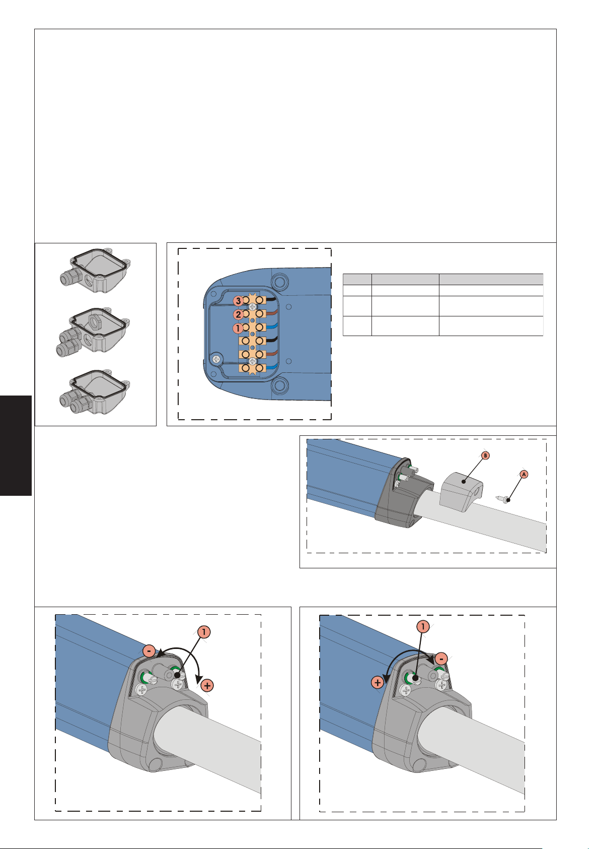
4.6. Final de carrera
Los modelos “LS” disponen de finales de carrera tanto en apertura como en cierre, por lo que requieren el uso de un equipo
electrónico capaz de gestionar estas entradas.
Nota: Los finales de carrera intervienen en los primeros y últimos 30 mm de la carrera. Por lo tanto es necesario que el operador,
durante la fase de apertura, utilice toda la carrera que tiene a disposición. Carreras menores podrían limitar o incluso anular
completamente el campo de regulación de los finales de carrera.
4.6.1. Cableado de los finales de carrera
El cableado de los finales de carrera se realiza en la misma regleta de bornes donde se ha realizado el cableado del motor. Para
realizar el cableado de los finales de carrera proceda del siguiente modo:
1) Abra el segundo orificio pretaladrado presente en la tapa, Fig.17.
2) Monte el sujeta-cables suministrado en dotación, Fig.17.
3) Introduzca el cable y conéctelo a los bornes respetando los colores indicados en la tabla de la Fig.18.
4) Cierre la tapa con los cuatro tornillos suministrados en dotación.
Nota:
• Para la conexión de los finales de carrera utilice un cable para colocación móvil para el exterior con conductores de sección
0.5 mm2.
• Durante el cableado preste atención a los colores de los hilos, respetando las indicaciones de la tabla en la Fig.18.
.SOP ROLOC NÓICPIRCSED
1 luzAnúmoC
2 nórraM
3 orgeN
)CCF(
)ACF(
erreicedarerracedlaniF
arutrepaedarerracedlaniF
Fig. 17
4.6.2. Regulación de los finales de carrera
Para regular los finales de carrera proceda del siguiente modo:
1) Destornille el tornillo de fijación superior, Fig.19 ref.A, y extraiga
la tapa, Fig.19 ref.B.
ESPAÑOL
2) Para regular el final de carrera de cierre FCC use el tornillo de
regulación, Fig.20 ref.1, girándolo en sentido horario para aumentar la carrera del vástago y viceversa, girándolo en sentido
antihorario para reducirla.
3) Para regular el final de carrera de apertura FCA use el tornillo
de regulación, Fig.21 ref.1, girándolo en sentido antihorario
para aumentar la carrera del vástago y viceversa, girándolo
en sentido horario para reducirla.
4) Realice un par de ciclos de prueba para comprobar que los
finales de carrera estén correctamente colocados. Si fuera
necesario regular de nuevo los finales de carrera, repita las operaciones a partir del punto 2.
5) Reponga de nuevo la tapa, Fig.19 ref.B, y apriete el tornillo de fijación, Fig.19 ref.A.
Fig. 18
Fig. 19
Fig. 20
Fig. 21
34
Page 45
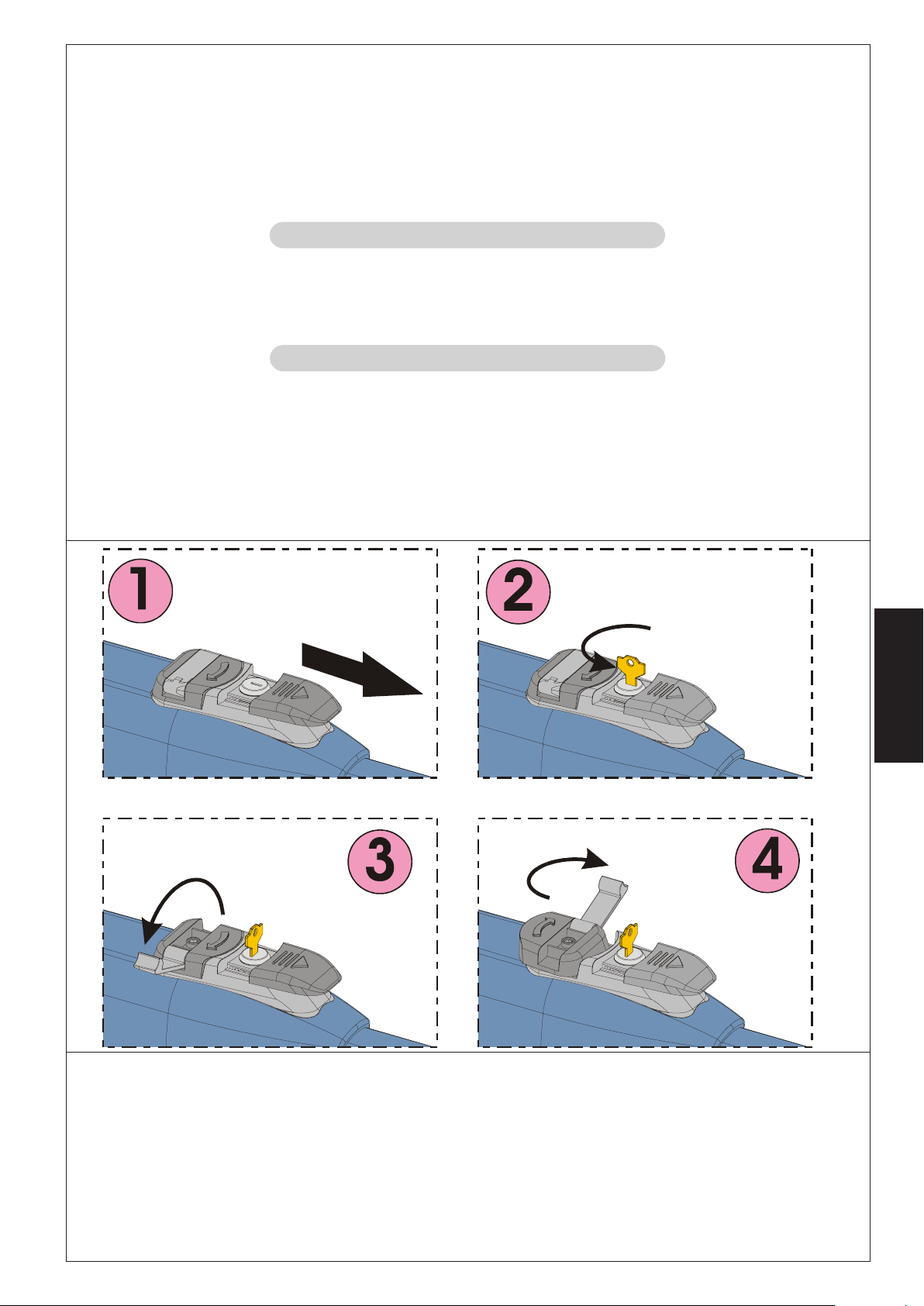
4.7. Puesta en funcionamiento
ATENCIÓN: Antes de efectuar cualquier intervención en el equipo o en el operador, quite la alimentación eléctrica.
Siga escrupulosamente los puntos 10, 11, 12, 13 y 14 de las OBLIGACIONES GENERALES PARA LA SEGURIDAD.
Siguiendo las indicaciones de la Fig.3, prepare los canales para los cables y realice las conexiones eléctricas del equipo electrónico
y de los accesorios elegidos.
Separe siempre los cables de alimentación de los cables de mando y de seguridad (pulsador, receptor, fotocélulas, etc.). Para
evitar interferencias eléctricas en la central utilice vainas separadas.
1) Alimente el sistema y compruebe el estado de los diodos, siguiendo los datos de la tabla presente en las instrucciones del
equipo electrónico.
2) Programe el equipo electrónico en función de sus exigencias y siguiendo las correspondientes instrucciones.
5. PRUEBA DE LA AUTOMACIÓN
• Compruebe que tanto la automación como todos los accesorios a la misma conectados funcionen correctamente, prestando
especial atención a los dispositivos de seguridad.
• Entregue al usuario final las instrucciones “Guía para el Usuario” y la hoja de Mantenimiento.
• Explique detenidamente al usuario el correcto funcionamiento y utilización de la automación.
• Indique al usuario las zonas de potencial peligro de la automación.
6. FUNCIONAMIENTO MANUAL
Si fuera necesario mover la automación a mano, por ejemplo por un corte de corriente o un fallo del operador, proceda del
siguiente modo:
1) Quite la alimentación eléctrica por medio del interruptor diferencial (también en caso de corte de corriente).
2) Deslice el capuchón de protección, Fig.22/1.
3) Introduzca la llave y gírela 90°, Fig.22/2.
4) Levante la palanca de maniobra, Fig.22/3 .
5) Para desbloquear el operador, gire 180° la palanca de manivela en la dirección indicada por la flecha presente en el sistema
de desbloqueo, Fig.22/4.
6) Efectúe la maniobra de apertura o cierre de la hoja.
Fig. 22
Nota: Para mantener el operador en funcionamiento manual es absolutamente necesario dejar el dispositivo de desbloqueo en
la posición actual y el equipo sin alimentación.
6.1. Restablecimiento del funcionamiento normal
Para restablecer las condiciones de funcionamiento normal proceda del siguiente modo:
1) Gire el sistema de desbloqueo 180° en la dirección opuesta a la indicada por la flecha.
2) Gire 90° la llave de desbloqueo y quítela.
3) Cierre de nuevo la palanca de mando y la tapa de protección.
4) Alimente el equipo y realice algunas maniobras para comprobar que todas las funciones de la automación se han restablecido
correctamente.
ESPAÑOL
35
Page 46

7. MANTENIMIENTO
Para asegurar un correcto funcionamiento a lo largo del tiempo y un constante nivel de seguridad es conveniente realizar, con
periodicidad semestral, un control general del equipo. En el fascículo “Guía para el Usuario” se ha preparado un módulo para
anotar las intervenciones.
8. REPARACIÓN
Para eventuales reparaciones diríjase a los Centros de Reparación autorizados.
9. ACCESORIOS DISPONIBLES
Para los accesorios disponibles consulte el catálogo.
10. APLICACIONES ESPECIALES
No están previstas aplicaciones distintas de la descrita
ESPAÑOL
36
Page 47

INHALTSVERZEICHNIS
Konformitätserklärung pag.37
Beschreibung pag.38
Technische Daten pag.39
Installation pag.39
Prüfung der Automation pag.44
Manuelle Betriebsweise pag.44
Wartung pag.45
Reparatur pag.45
Verfügbares Zubehör pag.45
Spezielle anwendungen pag.45
CE-KONFORMITÄTSERKLÄRUNG FÜR MASCHINEN
(RICHTLINIE 98/37/EG)
Hersteller: GENIUS S.p.a.
Adresse: Via Padre Elzi, 32 - 24050 - Grassobbio BERGAMO - ITALIEN
erklärt hiermit, dass: der Antrieb Modell MISTRAL
• zum Einbau in eine Maschine oder mit anderen Maschinen zum Bau einer Maschine im Sinne der Richtlinie 98/37/EG vorgesehen
ist.
• den wesentlichen Sicherheitsbestimmungen der anderen EWG-Richtlinien entspricht:
73/23/EWG und nachträgliche Änderung 93/68/EWG
89/336/EWG und nachträgliche Änderung 92/31/EWG sowie 93/68/EWG
und erklärt außerdem, dass die Inbetriebnahme solange untersagt ist, bis die Maschine, in welche diese Maschine eingebaut wird
oder von der sie ein Bestandteil ist, den Bestimmungen der Richtlinie 89/37/EG entspricht.
Grassobbio, 01-06-2005
Geschäftsführer
D.Gianantoni
DEUTSCH
37
Page 48

AUTOMATION MISTRAL
2. BESCHREIBUNG
Die Automation MISTRAL für Flügeltore ist ein irreversibler elektromechanischer Antrieb, der über ein Schneckensystem die Bewegung
auf den Flügel überträgt.
Der Antrieb ist in mehreren Ausführungen für alle Einbaubedürfnisse erhältlich. Die Ausführungen „LS” verfügen über Endschalter
beim Öffnen und beim Schließen.
Das irreversible System gewährleistet die mechanische Verriegelung des Flügels, wenn der Motor nicht in Betrieb ist. Ein praktisches
und sicheres Freigabesystem mit individuellem Schlüssel ermöglicht die manuelle Bewegung des Flügels bei Betriebsstörungen oder
Stromausfall.
ACHTUNG:
• Der ordnungsgemäße Betrieb und die erklärten Daten werden nur mit Zubehör und Sicherheitsvorrichtungen der Marke GENIUS
erreicht.
• Das Fehlen einer mechanischen Kupplungsvorrichtung erfordert zur Gewährleistung des erforderlichen Quetschschutzes den
Einsatz eines Steuergeräts mit einstellbarer elektronischer Kupplung.
• Die Automation MISTRAL wurde für die Zufahrtskontrolle von Fahrzeugen entwickelt und hergestellt, andere Anwendungen sind
zu vermeiden.
.soP gnubierhcseB .soP gnubierhcseB
1rotomebeirteG5legüBreretniH
2gnuthcirrovsgnulegeirtnE6ssulhcsnAreredroV
3tfahcS7ssulhcsnAreretnihtf
4legüBreredroV8etsielnemmelKgnukcedbA
itS
2
3
2.1. Abmessungen
DEUTSCH
155
1
4
5
7
6
8
Abb. 1
100
840 (MISTRAL 300)
935 (MISTRAL 400)
Abb. 2
38
Page 49

3. TECHNISCHE DATEN
NETADEHCSINHCET 003
003
SL
004
004
SL
423
423
SL
424
424
SL
423
-V511-
SL423
-V511-
gnugrosrevmortS~V032cdV42~V511
)W(gnutsieL00307003
)A(ekrätsmortS3.13 5.2
)C°(ztuhcsrutarepmeT041- 041
)Fµ(r
otasnednoK8-52
)Nad(buhcS003082003
)mm(buH003004003004003004
)ces/mc(
tfahcStiekgidniwhcsegsgnagsuA
F3
)m(.xamlegül
C°02iebtiekgifuähztasniEdnupyT
iR
iebednutSorpnelkyZebagnathc
C°02
)1(
3S
3S
%03
%53
4
3S
%03
03~52~57~03~52~
6,158.1
)2(
3S
%53
)1(
3
)2(
4
%001
)1(
3
3S
%03
3S
%53
)C°(trosgnulletsfuAmarutarepmeT 55+02-
)gk(sbeirtnAsedthciweG8.788.78 8.78
L 2.bbAeheiS
)mm(sbeirtnAsedegnä
)mm(sbeirtnAsednegnussembA 2.bbAeheiS
traztuhcS 44PI
(1)
Bei Torflügeln über 2.5 m muss das Elektroschloss eingebaut werden, um die Verriegelung des Flügels zu gewährleisten
(2)
Bei Torflügeln über 3 m muss das Elektroschloss eingebaut werden, um die Verriegelung des Flügels zu gewährleisten
424
-V511-
4
3S
%03
SL424
-V511-
)2(
3S
%53
3.1. Ausführungen
LLEDOM GNURHÜFSUA
003LARTSIM~V032rotomebeirteGrelbisreverrI
SL003LARTSIM neßeilhcS/nenffÖmiebnretlahcsdnEtim~V03
2rotomebeirteGrelbisreverrI
004LARTSIM~V032rotomebeirteGrelbisreverrI
SL004LARTSIM neßeilhcS/nenffÖmiebnr
423LARTSIMcdV42rotomebeirteGrelbisreverrI
SL423LARTSIM neßei
424LARTSIMcdV42rotomebeirteGrelbisreverrI
SL424LARTSIM neßeilhcS/nenffÖmiebnretlahcsdnEtimcdV42rotomebeirteGrelbisreverrI
V511-003LARTSIM~V511roto
V511-SL003LARTSIM neßeilhcS/nenffÖmiebnretlahcsdnEtim~V511rotomebeirteGrelbisrev
errI
mebeirteGrelbisreverrI
V511-004LARTSIM~V511rotomebeirteGrelbisreverrI
V511-SL004LARTSIM neßeilhcS/nenffÖmiebnretlahcsdnEtim
Bei Antrieben mit Zulassung nach CSA-UL muss zur Beibehaltung der Zulassung die Steuereinheit 455 MPS UL 115
4.1. Elektrische Einrichtungen (Standardanlage)
~V511rotomebeirteGrelbisreverrI
verwendet werden.
4. INSTALLATION
.soP gnubierhcseB
1ebeirtnA
2nellezotohP
3täreGsehcsinortkelE
4etsatlessülhcS
5regnäfpmE
6epmalknilB
etlahcsdnEtim~V032rotomebeirteGrelbisreverrI
lhcS/nenffÖmiebnretlahcsdnEtimcdV42rotomebeirteGrelbisreverrI
DEUTSCH
Anmerkungen:
• Für die Verlegung der Stromkabel sind
entsprechende Rohre und/oder
Schläuche zu verwenden.
• Um Störungen zu vermeiden, sollten
die Anschlusskabel des Zubehörs mit
Niederspannung und die Schaltkabel
stets von den Versorgungskabeln mit
230/115 V~ mit Hilfe separater Mäntel
getrennt werden.
39
Abb. 3
Page 50
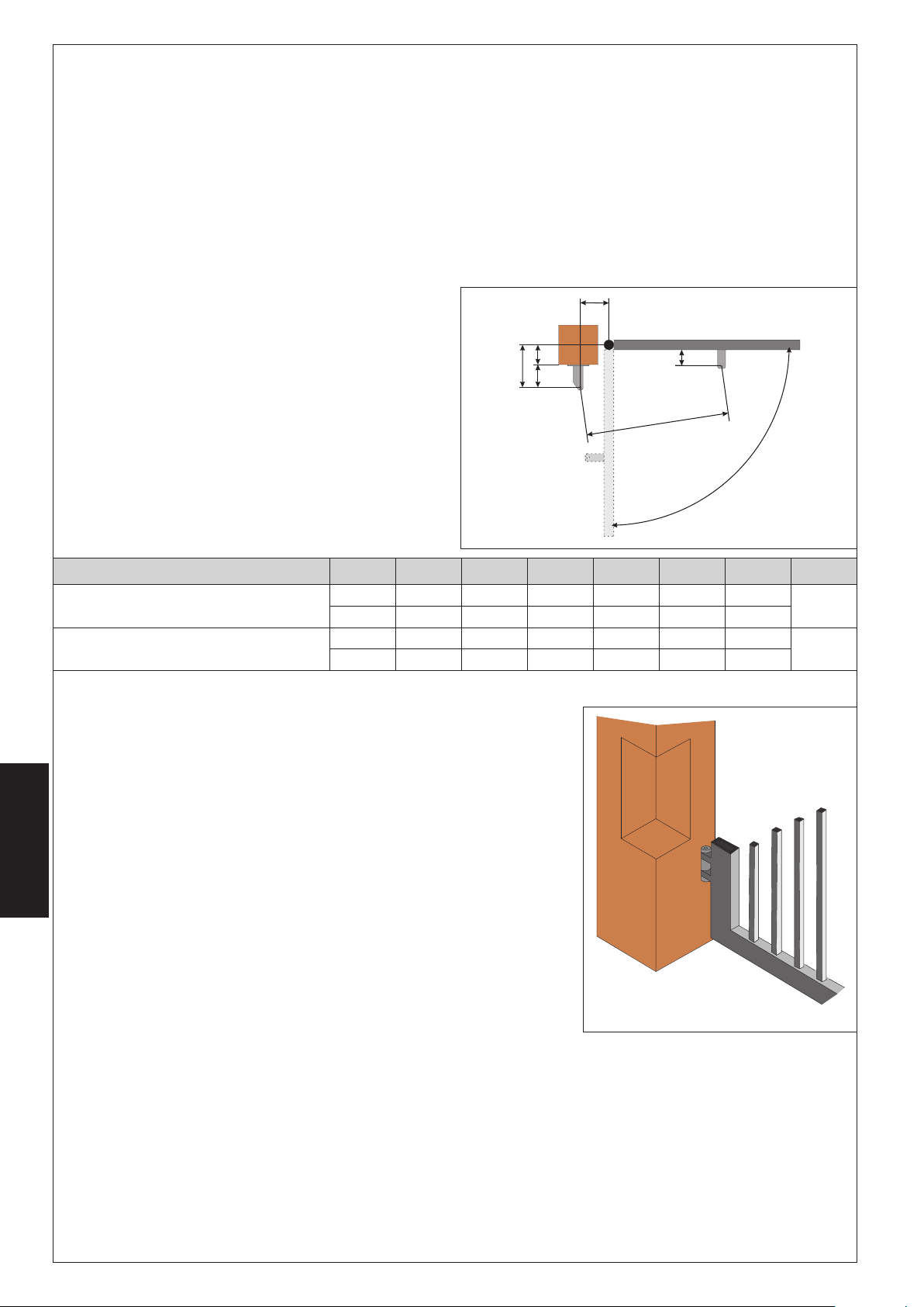
4.2. Vorabprüfungen
Für den ordnungsgemäßen Betrieb der Automation muss der Aufbau des bereits bestehenden oder zu realisierenden Tors folgende
Merkmale aufweisen:
• Die mechanischen Bauelemente müssen den Anforderungen der Normen EN 12604 und EN 12605 entsprechen.
• Länge des Flügels entsprechend den Eigenschaften des Antriebs.
• Struktur der Flügel robust und steif, geeignet für die Automation
• gleichmäßige und reibungslose Bewegung der Flügel, ohne Reibungen und Schleichen während der gesamten Öffnung
• entsprechend robuste Scharniere in gutem Zustand
• mechanische Endanschläge beim Öffnen und beim Schließen
• effizienter Erdungsanschluss für den elektrischen Anschluss des Antriebs
Eventuelle Schlosserarbeiten sollten vor der Installation der Automation ausgeführt werden.
Der Zustand der Struktur des Tors beeinflusst direkt die Zuverlässigkeit und die Sicherheit der Automation.
4.3. Einbaumaße
Die Montageposition des Antriebs bestimmen und hierzu Bezug
auf die Abbildung 4 nehmen.
Aufmerksam sicherstellen, dass der Abstand zwischen dem
offenen Flügel und eventuellen Hindernissen (Wände,
Umzäunungen usw.) über dem Platzbedarf des Antriebs liegt.
(1)
Nutzhub des Antriebs
lledoM
V511-003/423/003LARTSIM
V511-004/424/004LARTSIM
(2)
Höchstmaß
α
°0954154109258060111
°01102153159206060111
°09591591093521070921
°01107107
(3)
Mindestmaß
4.3.1. Allgemeine Regeln für die Bestimmung der Einbaumaße
• für Öffnungen des Flügels bei 90° : A+B=C
• für Öffnungen des Flügels über 90° : A+B<C
• Niedrigere Maße A und B bestimmen höhere Peripheriegeschwindigkeiten des
Flügels.
• Den Unterschied zwischen dem Maß A und dem Maß B auf höchstens 4 cm
begrenzen: Höhere Unterschiede verursachen hohe Änderungen der
Geschwindigkeit beim Öffnen und Schließen des Tors.
• Das Maß Z ist so beizubehalten, dass der Antrieb nicht gegen den Pfosten stößt.
• Bei den Ausführungen LS sprechen die Endschalter in den ersten und letzten 30
mm an. Daher müssen solche Maße A und B verwendet werden, dass der gesamte
DEUTSCH
Hub des Antriebs ausgenutzt wird. Geringere Hubwege könnten den
Einstellbereich der Endschalter einschränken oder aufheben.
A B C
1093011060921
B
D
A
Z
)1(
D
E
L
a
Abb. 4
)2(
)3(
Z
L E
)3(
54
54
Wenn die Abmessungen des Pfostens oder die Position des Scharniers die Installation
des Antriebs nicht ermöglichen, muss zur Beibehaltung des bestimmten Maßes A eine
Nische auf dem Pfosten laut Angaben in Abb. 5 ausgeführt werden. Die Abmessungen
der Nische müssen so beschaffen sein, dass eine problemlose Installation und Drehung
des Antriebs und die Betätigung der Freigabevorrichtung ermöglicht wird.
40
Abb. 5
Page 51

4.4. Installation der Antriebe
1) Den hinteren Bügel an der zuvor bestimmten Position befestigen. Bei einem Eisenpfosten den Bügel fest direkt an den Pfosten
anschweißen (Abb. 6). Bei einem Pfosten aus Mauerwerk, die entsprechende Platte (Extra) zur Befestigung verwenden und
anschrauben (Abb. 7), unter Verwendung entsprechender Befestigungssysteme. Dann den Bügel sorgsam am Pfosten
festschweißen.
Bei der Befestigung mit einer Wasserwaage die perfekte Nivellierung des Bügels prüfen.
Abb. 6 Abb. 7
2) Den hinteren Anschluss des Antriebs laut Angaben in Abb. 8 zusammenbauen.
3) Den Antrieb für den manuellen Betrieb einrichten (siehe Abschnitt 6 )
4) Den Schaft bis zum Anschlag ganz entfernen, Abb.9 Bez.1.
5) Den Antrieb verriegeln (siehe Abschnitt 6.1 )
6) Den Schaft eine halbe/ganze Runde im Uhrzeigersinn drehen, Abb. 9 Bez.2
7) Den vorderen Bügel laut Angaben in Abb. 10 zusammenbauen.
1
2
Abb. 9 Abb. 10
8) Den Antrieb am hinteren Bügel mit Hilfe der im Lieferumfang enthaltenen Stifte
befestigen, siehe Abb. 11.
Abb. 8
DEUTSCH
41
Abb. 11
Page 52

9) Den Flügel schließen und dabei den Antrieb perfekt
waagrecht halten und den Befestigungspunkt des
vorderen Bügels bestimmen (Abb. 12).
10) Den vorderen Bügel provisorisch mit Hilfe von zwei
Schweißpunkten befestigen (Abb. 12).
Anmerkung: Wenn der Aufbau des Tors eine solide
Befestigung des Bügels nicht ermöglicht, müssen
Arbeiten an der Struktur vorgenommen und eine
solide Auflagefläche geschaffen werden.
11) Den Antrieb entriegeln (siehe Abschnitt 6) und mit
der Hand sicherstellen, dass das Tor sich vollkommen
frei öffnen kann und an den mechanischen
Anschlägen zum Stillstand kommt und dass die
Bewegung des Flügels regelmäßig und reibungslos
erfolgt.
12) Die erforderlichen Korrekturarbeiten ausführen und
dann die Schritte ab Punkt 8 wiederholen.
13) Den Antrieb kurzzeitig aus dem vorderen Bügel
befreien und den Bügel endgültig festschweißen.
Abb. 12 Abb. 13
Falls die Struktur des Flügels das Anschweißen des Bügels
nicht erlaubt, kann der entsprechende anzuschraubende Bügel (Extra) mit geeigneten Befestigungssystemen (Abb. 13) verwendet
werden. Dann sind die Anweisungen für den anzuschweißenden Bügel zu befolgen.
Anmerkung: Alle Befestigungsstifte der Anschlüsse sollten eingefettet werden
4.5. Verkabelung des Antriebs
Am unteren Teil des Antriebs befindet sich eine Klemmenleiste für den Anschluss des Motors, der eventuellen
Endschalter und die Erdung des Antriebs.
ACHTUNG: Für den Anschluss des Motors muss das im Lieferumfang enthaltene Kabel für das bewegliche
Teilstück oder alternativ ein Kabel für die bewegliche Verlegung von außen verwendet werden.
Für die Verkabelung des Motors sind folgende Schritte auszuführen:
1) Eine der beiden vorperforierten Öffnungen auf dem mitgelieferten Deckel durchbrechen, Abb. 14. Bei
Antrieben mit Endschalter müssen beide Öffnungen durchbrochen werden.
2) Die im Lieferumfang enthaltene Kabelverschraubung montieren.
3) Die Anschlüsse des Motors und der Erdung unter Bezugnahme auf die Abb. 15 und die Tabelle ausführen.
Bei Antrieben mit Zulassung nach CSA-UL muss der Kondensator zur Beibehaltung der
Zulassung stabil in einem nach CSA-UL zugelassenen Gehäuse positioniert werden.
.SOP EBRAF GNUBIERHCSEB
1 )ßieW(ualBtkatnoklemmaS
2 )toR(nuarB1esahP
3 )zrawhcS(zrawhcS2esahP
T )nürG(nürG/bleGgnudrE
DEUTSCH
.SOP EBRAF GNUBIERHCSEB
1 ualB1esahP
2 tednewrevthciN/
3 nuarB2esahP
T tednewrevthciN/
Abb. 14
)~V511(~V032LARTSIM
cdV42LARTSIM
4) Den Deckel mit den vier mitgelieferten Schrauben verschließen,
Abb. 16.
Abb. 15
Abb. 16
42
Page 53

4.6. Endschalter
Die Modelle „LS” verfügen über Endschalter sowohl beim Öffnen als auch beim Schließen und erfordern somit den Einsatz eines
elektronischen Steuergeräts zur Steuerung dieser Eingänge.
Anmerkung: Die Endschalter lösen auf den ersten und letzten 30 mm des Hubs aus. Der Antrieb muss daher in der Öffnungsphase
den gesamten zur Verfügung stehenden Hubweg nutzen. Geringere Hubwege können den Einstellbereich der Endschalter
einschränken oder vollständig aufheben.
4.6.1. Verkabelung der Endschalter
Die Verkabelung der Endschalter wird auf derselben Klemmenleiste vorgenommen, auf der die Verkabelung des Motors ausgeführt
wurde. Für die Verkabelung der Endschalter sind die nachfolgenden Schritte auszuführen:
1) Auch die zweite vorperforierte Öffnung auf dem Deckel durchbrechen, Abb. 17.
2) Die mitgelieferte Kabelführung montieren, Abb. 17
3) Das Kabel einziehen und an die Klemmen anschließen, wobei die in der Tabelle Abb. 18 angegebenen Farben zu beachten
sind.
4) Den Deckel mit den vier mitgelieferten Schrauben verschließen.
Anmerkung:
• Für den Anschluss der Endschalter ein Kabel für mobile Verlegung von außen mit Leitern mit Querschnitt 0.5 mm2 verwenden.
• Bei der Verkabelung auf die Farben der Drähte laut Angaben in der Tabelle Abb. 18 achten.
.SOP EBRAF GNUBIERHCSEB
1 ualBtkatnoklemmaS
2 nuarB
3 zrawhcS
)CCF(
)ACF(
neßeilhcSmiebretlahcsdnE
nenffÖmiebretlahcsdnE
Abb. 17
4.6.2. Einstellung der Endschalter
Für die Einstellung der Endschalter sind die nachfolgenden Schritte
vorzunehmen:
1) Die obere Befestigungsschraube lösen, Abb.19 Bez.A, und den
Deckel entfernen, Abb.19 Bez.B.
2) Die Einstellung des Endschalters beim Schließen FCC erfolgt
durch die Einstellschraube, Abb.20 Bez.1: im Uhrzeigersinn
drehen, um den Hub des Schafts zu erhöhen, im
Gegenuhrzeigersinn, um den Hub zu verringern.
3) Die Einstellung des Enschalters beim Öffnen FCA erfolgt durch
die Einstellschraube, Abb.21 Bez.1: im Gegenuhrzeigersinn
drehen, um den Hub des Schafts zu erhöhen, im Uhrzeigersinn,
um den Hub zu verringern.
4) Ein paar Probezyklen ausführen, um die korrekte Positionierung
der Endschalter zu überprüfen. Solle die Notwendigkeit bestehen, die Endschalter erneut einzustellen, sind die Vorgänge ab
Punkt 2 zu wiederholen.
5) Den Deckel erneut positionieren, Abb.19 Bez.B, und die Befestigungsschraube festziehen, Abb.19 Bez.A.
Abb. 18
Abb. 19
DEUTSCH
Abb. 20
Abb. 21
43
Page 54

4.7. Inbetriebnahme
ACHTUNG: Vor Arbeiten an der Anlage oder dem Antrieb ist stets die Stromversorgung abzuschalten.
Die Punkte 10, 11, 12, 13 und 14 der ALLGEMEINEN SICHERHEITSVORSCHRIFTEN sind genauestens zu befolgen.
Unter Beachtung der Angaben aus Abb. 3 die Kabelkanäle einrichten und die elektrischen Anschlüsse des elektronischen
Steuergeräts und der ausgewählten Zubehörteile ausführen.
Die Versorgungskabel sind stets von den Schalt- und Sicherheitskabeln zu trennen (Taste, Empfänger, Lichtschranke usw.). Damit
keine elektrischen Störungen im Steuergerät entstehen, sind getrennte Mäntel zu verwenden.
1) Das System mit Strom versorgen und den Zustand der LED anhand der in den Anweisungen für das elektronische Steuergerät
enthaltenen Tabelle prüfen.
2) Das elektronische Gerät je nach den eigenen Bedürfnissen und den entsprechenden Anweisungen programmieren.
5. PRÜFUNG DER AUTOMATION
• Eine sorgfältige Funktionsprüfung der Automation und aller damit verbundenen Zubehörteile vornehmen, wobei besonders auf
die Sicherheitsvorrichtungen zu achten ist.
• Dem Endanwender das Heft „Anweisungen für den Benutzer” und das Wartungsmerkblatt übergeben.
• Den Benutzer korrekt über die ordnungsgemäße Betriebsweise und die Anwendung der Automation unterrichten.
• Dem Benutzer die potentiellen Gefahrenbereiche der Automation signalisieren.
6. MANUELLE BETRIEBSWEISE
Sollte die manuelle Bewegung der Automation erforderlich sein aufgrund von Stromausfall oder Betriebsstörungen des Antriebs, sind
die nachfolgenden Schritte auszuführen:
1) Mit Hilfe des Differentialschalters (auch bei Stromausfall) die Stromversorgung unterbrechen.
2) Die Schutzhaube – Abb. 22/1 – gleiten lassen.
3) Den Schlüssel einstecken und um 90° drehen, Abb.22/2.
4) Den Bedienhebel heben, Abb. 22/3
5) Zur Freigabe des Antriebs den Bedienhebel um 180° in Richtung des auf dem Freigabesystem angegebenen Pfeils drehen, Abb.
22/4.
6) Den Vorgang zum Öffnen oder Schließen des Flügels manuell ausführen.
DEUTSCH
Anmerkung: Zur Beibehaltung des manuellen Betriebs des Antriebs muss die Freigabevorrichtung unbedingt in ihrer aktuellen
Position gelassen werden und die Stromzufuhr zur Anlage muss weiterhin unterbrochen bleiben.
6.1. Wiederherstellung des Normalbetriebs
Zur Wiederherstellung der normalen Betriebsbedingungen sind die nachfolgenden Schritte auszuführen:
1) Das Freigabesystem um 180° in die entgegen gesetzte Richtung des Pfeils drehen.
2) Den Freigabeschlüssel um 90° drehen und herausziehen.
3) Den Bedienhebel und den Schutzdeckel verschließen.
4) Die Anlage mit Strom versorgen und einige Vorgänge ausführen, um die korrekte Wiederherstellung aller Funktionen der Automation
zu prüfen.
44
Abb. 22
Page 55

7. WARTUNG
Damit langfristig eine ordnungsgemäße Betriebsweise und ein konstantes Sicherheitsniveau gewährleistet werden, ist im Abstand
von 6 Monaten eine allgemeine Kontrolle der Anlage vorzunehmen. Im Heft „Anweisungen für den Benutzer” ist ein Formular für die
Aufzeichnung der Arbeiten enthalten.
8. REPARATUR
Eventuelle Reparaturen sind von einem Vertrags-Center auszuführen.
9. VERFÜGBARES ZUBEHÖR
Für das verfügbare Zubehör wird auf den Katalog verwiesen.
10. SPEZIELLE ANWENDUNGEN
Neben der beschriebenen sachgemäßen Anwendung sind keine weiteren Anwendungen vorgesehen.
45
DEUTSCH
Page 56

INHOUD
Verklaring van overeenstemming pag.46
Beschrijving pag.47
Technische eigenschappen pag.48
Installatie pag.48
Test van het automatische systeem pag.53
Werking met handbediening pag.53
Onderhoud pag.54
Reparatie pag.54
Leverbare accessoires pag.54
Bijzondere toepassingen pag.54
CE-VERKLARING VAN OVEREENSTEMMING VOOR MACHINES
(RICHTLIJN 98/37/EG)
Fabrikant: GENIUS S.p.a.
Adres: Via Padre Elzi, 32 - 24050 - Grassobbio BERGAMO - ITALIË
Verklaart dat:de aandrijving mod. MISTRAL
• gebouwd is voor opname in een machine of voor assemblage met andere machines, zodat er een machine gevormd wordt in
de zin van de Richtlijn 98/37/EG;
• in overeenstemming is met de fundamentele veiligheidseisen van de volgende andere EEG-richtlijnen:
73/23/EEG en latere wijziging 93/68/EEG.
89/336/EEG en latere wijziging 92/31/EEG en 93/68/EEG
en verklaart bovendien dat het niet toegestaan is de machine in bedrijf te stellen totdat de machine waarin hij zal worden
opgenomen of waarvan hij deel uit zal maken geïdentificeerd is, en in overeenstemming verklaard is met de Richtlijn 98/37/EG.
NEDERLANDS
Grassobbio, 01-06-2005
De algemeen directeur
D.Gianantoni
46
Page 57

AUTOMATISCH SYSTEEM MISTRAL
2. BESCHRIJVING
Het automatische systeem MISTRAL voor poorten met draaiende vleugels is een onomkeerbare elektromechanische aandrijving
die de beweging op de vleugel overdraagt via een wormschroefsysteem.
De aandrijving is leverbaar in verschillende uitvoeringen, zodat aan alle installatie-eisen kan worden voldaan. De uitvoeringen “LS”
hebben eindschakelaars bij opening en sluiting.
Het onomkeerbare systeem garandeert mechanische vergrendeling van de vleugel wanneer de motor niet in werking is. Een
praktisch, veilig ontgrendelsysteem met individuele sleutel maakt handmatige verplaatsing van de vleugel mogelijk als het systeem
niet goed werkt of als de stroom is uitgevallen.
LET OP:
• Het systeem kan alleen correct werken en heeft alleen de verklaarde eigenschappen als er GENIUS accessoires en
veiligheidsvoorzieningen worden gebruikt.
• Aangezien er geen mechanische koppeling aanwezig is, dient er een bedieningsunit met regelbare elektronische koppeling te
worden gebruikt om de nodige beveiliging tegen inklemming te garanderen.
• Het automatische systeem MISTRAL is ontworpen en gebouwd voor controle op de toegang door voertuigen. Het mag niet voor
andere doeleinden worden gebruikt.
.soP gnivjirhcseB .soP gnivjirhcseB
1gnigartrevrotoM5leguebetsrethcA
2emsinahcemlednergtnO6gnigitsevebetsrethcA
3leetS7gnigitsevebetsret
4leguebetsrooV8drobnemmelkleskeD
2
hcaneP
3
5
2.1. Afmetingen
155
1
4
7
6
8
Fig. 1
100
840 (MISTRAL 300)
NEDERLANDS
935 (MISTRAL 400)
Fig. 2
47
Page 58

3. TECHNISCHE EIGENSCHAPPEN
NEPPAHCSNEGIEEHCSINHCET 003
003
SL
gnideoV~V032cdV42~V511
)W(negomreV00307003
)A(moortS3.13 5.2
)C°(gnigilievebehcsimrehT041- 041
oC8-52
)Fµ(rotasnedn
)Nad(thcarkwuD003082003
)mm(galS003004003004003004
)ces/mc(leetsdiehlenssgnagtiU 6,158.1
)m(.xamleguelV3
C°02jibeitneuqerfskiurbegneepyT
latnaA
)gniredanebjib(ruurepilcyc
C°02jib
)1(
3S
3S
%03
3S
%53
03~52~57~03~52~
)C°(ruutarepmetsgnivegmO 55+02-
)gk(gnivjirdnaathciweG8.788.78 8.78
eL 2.gifeiz
)mm(gnivjirdnaaetgn
)mm(gnivjirdnaanegnitemfA 2.gifeiz
daargsgnimrehcseB 44PI
(1)
Bij vleugels van meer dan 2,5 m lengte is installatie van een elektroslot verplicht, om vergrendeling van de vleugel te waarborgen
(2)
Bij vleugels van meer dan 3 m lengte is installatie van een elektroslot verplicht, om vergrendeling van de vleugel te waarborgen
004
004
SL
)2(
4
3S
%03
%53
423
423
SL
)1(
3
%001
424
424
SL
)2(
4
423
-V511-
3
3S
%03
SL423
424
-V511-
)1(
3S
%53
-V511-
)2(
4
3S
%03
SL424
-V511-
3S
%53
3.1. Uitvoeringen
LEDOM GNIREOVTIU
003LARTSIM~V032gnigartrevrotomerabreekmonO
SL003LARTSIM gnitiuls/gnineporoovraalekahcsdnietemn
004LARTSIM~V032gnigartrevrotomerabreekmonO
SL004LARTSIM gnitiuls/gninep
423LARTSIMcdV42gnigartrevrotomerabreekmonO
SL42
3LARTSIM gnitiuls/gnineporoovraalekahcsdnietemnecdV42gnigartrevrotomerabreekmonO
424LARTSIMcdV42gnigartr
SL424LARTSIM gnitiuls/gnineporoovraalekahcsdnietemnecdV42gnigartrevrotomerabreekmon
O
evrotomerabreekmonO
~V511-003LARTSIM~V511gnigartrevrotomerabreekmonO
~V511-SL003LARTSIM gnitiuls/gnineporoovraalekahcsdniet
~V511-004LARTSIM~V511gnigartrevrotomerabreekmonO
~V511-SL004LARTSIM
Bij aandrijvingen met CSA-UL-keurmerk moet het besturingssysteem 455 MPS UL 115 worden gebruikt om de
homologatie te handhaven.
4. INSTALLATIE
4.1. Elektrische aansluitmogelijkheden (standaard installatie)
.soP gnivjirhcseB
1negnivjirdnaA
2nellecotoF
3ruutarappaehcsinortkelE
4raalekahcsletuelS
5regnavtnO
NEDERLANDS
6pmalsgniwuhcsraaW
e~V032gnigartrevrotomerabreekmonO
oroovraalekahcsdnietemne~V032gnigartrevrotomerabreekmonO
emne~V511gnigartrevrotomerabreekmonO
gnitiuls/gnineporoovraalekahcsdnietemne~V511gnigartrevrotomerabreekmonO
Opmerkingen:
• Voor het plaatsen van de
elektriciteitskabels moeten geschikte
starre en/of buigzame leidingen
worden gebruikt
• Om interferenties te voorkomen
wordt geadviseerd de
verbindingskabels van de
accessoires op laagspanning en de
bedieningskabels gescheiden te
houden van de voedingskabels 230/
115 V~ door gebruik te maken van
aparte buizen.
Fig. 3
48
Page 59

4.2. Voorbereidende controles
Voor een goede werking van het automatische systeem moet de constructie van de al bestaande of nog te realiseren poort aan
de volgende eisen voldoen:
• de mechanische bouwelementen moeten in overeenstemming zijn met de bepalingen van de normen EN 12604 en EN 12605.
• de lengte van de vleugel dient in overeenstemming te zijn met de eigenschappen van de aandrijving.
• de constructie van de vleugels dient stevig en stijf te zijn, geschikt voor het automatische systeem
• de beweging van de vleugels moet regelmatig en gelijkmatig zijn, zonder wrijvingen en verstroevingen langs de hele
openingsbeweging
• de scharnieren moeten voldoende stevig en in goede staat zijn
• er moeten mechanische eindaanslagen voor opening en sluiting zijn
• er dient een goede aarding aanwezig te zijn voor de elektrische aansluiting van de aandrijving
Het wordt aanbevolen eventuele smidswerkzaamheden uit te voeren voordat het automatische systeem geïnstalleerd wordt.
De staat van de constructie van de poort is direct van invloed op de betrouwbaarheid en de veiligheid van het automatische
systeem.
4.3. Installatiematen
Bepaal de montagepositie van de aandrijving aan de hand
van fig.4.
Controleer zorgvuldig of de afstand tussen de geopende vleugel
en eventuele obstakels (muren, omheiningen, enz.) groter is dan
de ruimte die de aandrijving nodig heeft.
ledoM
V511-004/424/004LARTSIM
(1)
nuttige slag van de aandrijving
α
V511-003/423/003LARTSIM
°0954154109258060111
°01102153159206060111
°09591591093521070921
°01107107
(2)
maximum afmeting
A B C
1093011060921
4.3.1. Algemene regels voor het bepalen van de installatiematen
• voor openingen van de vleugel onder 90°: A+B=C
• voor openingen van de vleugel van meer dan 90°: A+B<C
• kleinere maten A en B hebben hogere perifere snelheden van de vleugel tot
gevolg.
• het verschil tussen maat A en maat B mag niet groter zijn dan 4 cm: grotere
verschillen veroorzaken grote variaties in de snelheid tijdens de openende en
sluitende beweging van de poort.
• houd een maat Z aan, zodat de aandrijving niet tegen de pilaster stoot.
• bij de uitvoeringen LS worden de eindschakelaars ingeschakeld gedurende de
eerste en laatste 30 mm. Het is daarom noodzakelijk de maten A en B te gebruiken,
om de hele slag van de aandrijving te benutten. Kleinere slagen zouden het
regelveld van de eindschakelaars kunnen beperken of teniet kunnen doen.
D
A
Z
(3)
minimum afmeting
B
E
L
a
Fig. 4
)1(
)2(
D
)3(
Z
L E
)3(
54
54
Als de afmetingen van de pilaster of de positie van het scharnier het niet mogelijk
maken de aandrijving te installeren, moet er een nis in de pilaster worden gemaakt
om de maat A te kunnen respecteren, zoals aangegeven op fig. 5. De afmetingen
van de nis moeten zodanig zijn dat de aandrijving gemakkelijk kan worden
geïnstalleerd en kan draaien, en dat het ontgrendelmechanisme kan worden
bediend.
49
Fig. 5
NEDERLANDS
Page 60
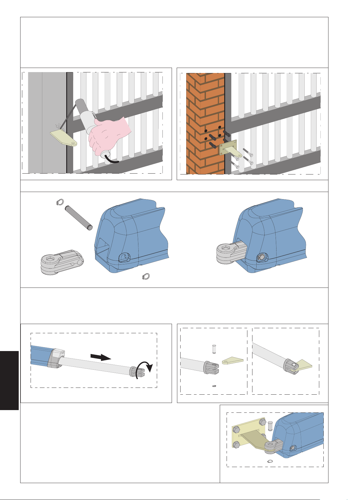
4.4. Installatie van de aandrijvingen
1) Bevestig de achterste beugel op de plaats die u eerder heeft bepaald. In het geval van ijzeren pilasters moet de beugel
nauwkeurig direct op de pilaster worden gelast (fig. 6). In het geval van een gemetselde pilaster moet de speciale plaat (optie)
voor bevestiging met schroeven (fig. 7) worden gebruikt. Maak gebruik van geschikte bevestigingssystemen. Las de beugel
vervolgens nauwkeurig aan de plaat.
Controleer tijdens het bevestigen met een waterpas of de beugel perfect horizontaal is.
Fig. 6
2) Assembleer de achterste bevestiging van de aandrijving zoals aangegeven op fig.8.
3) Stel de aandrijving in op handbediening (zie par. 6)
4) Haal de steel helemaal naar buiten, tot aan de aanslag , fig. 9 ref. 1.
5) Vergrendel de aandrijving weer (zie par. 6.1)
6) Draai de steel een halve/hele slag met de klok mee, fig. 9 ref. 2
7) Assembleer de voorste beugel zoals aangegeven op fig.10.
Fig. 7
Fig. 8
1
2
NEDERLANDS
8) Bevestig de aandrijving aan de achterste beugel met de bijgeleverde pennen,
zoals aangegeven op fig.11.
Fig. 9
50
Fig. 10
Fig. 11
Page 61

9) Sluit de vleugel en zoek het bevestigingspunt van
de voorste beugel op terwijl u de aandrijving
perfect horizontaal houdt (fig.12).
10) Bevestig de voorste beugel voorlopig met twee
laspunten (fig.12).
Nota bene: als de beugel niet stevig aan de
constructie van de poort kan worden vastgezet,
moet er een stevige ondergrond op de constructie
van de poort worden aangebracht.
11) Ontgrendel de aandrijving (zie par. 6) en
controleer met de hand of de poort helemaal en
ongehinderd open kan gaan en stopt tegen de
mechanische eindaanslagen, en of de beweging
van de vleugel regelmatig en zonder wrijvingen
verloopt.
12) Voer de nodige correcties uit en herhaal de
handelingen vanaf punt 8.
13) Maak de aandrijving tijdelijk los van de voorste
beugel en las de beugel definitief.
Als het vanwege de constructie van de vleugel niet
Fig. 12 Fig. 13
mogelijk is de beugel te lassen, kan de speciale, met schroeven bevestigde beugel (optie)
worden gebruikt. Gebruik hiervoor geschikte bevestigingssystemen (fig. 13). Ga vervolgens te werk zoals wordt beschreven voor
de beugel die wordt gelast.
Nota bene: het is raadzaam alle bevestigingspennen van de bevestigingen in te vetten.
4.5. Bedrading van de aandrijving
Aan de onderkant van de aandrijving zit een klemmenbord voor aansluiting van de motor, de eventuele
eindschakelaars en de aarding van de aandrijving.
LET OP: voor de verbinding van de motor moet de bijgeleverde kabel worden gebruikt voor het
verplaatsbare gedeelte of anders een verplaatsbare kabel voor buiten.
Doe het volgende voor de bekabeling van de motor:
1) Maak een van de twee voorgeperforeerde gaten in het bijgeleverde deksel open, fig. 14. Bij
aandrijvingen met eindschakelaars moeten beide gaten worden opengemaakt.
2) Monteer de bijgeleverde kabelklem.
3) Maak de verbindingen met de motor en de aarding, zie hiervoor fig. 15 en de tabel.
Voor aandrijvingen met het CSA-UL-keurmerk is het verplicht de condensator stabiel te
bevestigen in een houder met CSA-UL-keurmerk, om de homologatie te handhaven.
.SOP RUELK GNIVJIRHCSEB
1 )knalB(wualBekjileppahcsneemeG
2 )tooR(niurB1esaF
3 )trawZ(trawZ2esaF
T
.SOP RUELK GNIVJIRHCSEB
1 wualB1esaF
2 tkiurbegteiN/
3 niurB2esaF
T tkiurbegteiN/
neorG/leeG
)neorG(
Fig. 14
)~V511(~V032LARTSIM
gnidraA
cdV42LARTSIM
Fig. 15
4) Sluit het deksel met de vier bijgeleverde schroeven, fig.16.
NEDERLANDS
Fig. 16
51
Page 62

4.6. Eindschakelaars
De modellen “LS” hebben eindschakelaars voor zowel de opening als de sluiting. Hierbij is dus elektronische apparatuur nodig die
in staat is deze ingangen te besturen.
Nota bene: de eindschakelaars treden in werking gedurende de eerste en laatste 30 mm van de slag. De aandrijving moet daarom
tijdens de openingsfase de hele beschikbare slag gebruiken. Kleinere slagen kunnen het regelveld van de eindschakelaars
verkleinen of helemaal annuleren.
4.6.1. Bekabeling van de eindschakelaars
De bekabeling van de eindschakelaars wordt gerealiseerd op hetzelfde klemmenbord als waarop de motorbekabeling is uitgevoerd.
Ga als volgt te werk om de eindschakelaars te bekabelen:
1) Maak ook het tweede voorgeperforeerde gat in het deksel open, fig. 17.
2) Monteer de bijgeleverde kabelklem, fig. 17.
3) Steek de kabel erdoorheen en verbind hem met de klemmen volgens de kleuren die gespecificeerd zijn in de tabel van fig. 18.
4) Sluit het deksel met de vier bijgeleverde schroeven.
Nota bene:
• Gebruik voor de verbinding van de eindschakelaars een verplaatsbare kabel voor buiten, met aders met een doorsnede van 0,5
mm2.
• Let bij de bekabeling op de kleuren van de draden, zoals gespecificeerd in de tabel van fig.18.
.SOP RUELK GNIVJIRHCSEB
1 wualBekjileppahcsneemeG
2 niurB
3 trawZ
)CCF(
)ACF(
gninepo
gnitiulsroovraalekahcsdniE
roovraalekahcsdniE
Fig. 17
4.6.2. Regeling van de eindschakelaars
Ga als volgt te werk om de eindschakelaars te regelen:
1) Draai de bovenste bevestigingsschroef, fig. 19 ref. A, los en
haal het dekseltje weg, fig. 19 ref. B.
2) Om de eindschakelaar voor sluiting FCC te regelen, draai
aan de stelschroef, fig. 20 ref. 1: draai hem met de klok mee om
de slag van de steel te vergroten, of tegen de klok in om de
slag te verkleinen.
3) Om de eindschakelaar voor opening FCA te regelen, draai
aan de stelschroef, fig. 21 ref. 1: draai hem tegen de klok in om
de slag van de steel te vergroten, of met de klok mee om de
slag te verkleinen.
4) Voer een paar testcycli uit om na te gaan of de eindschakelaar
correct geplaatst is. Als de eindschakelaar opnieuw moet worden geregeld, herhaal de handelingen dan vanaf punt 2.
5) Plaats het dekseltje, fig. 19 ref. B, weer en span de bevestigingsschroef, fig. 19 ref. A, opnieuw.
NEDERLANDS
Fig. 18
Fig. 19
Fig. 21
Fig. 22
52
Page 63

4.7. Ingebruikstelling
LET OP: alvorens ingrepen op de installatie of op de aandrijving te verrichten moet de elektrische voeding worden afgekoppeld.
Volg de punten 10, 11, 12, 13 en 14 van de ALGEMENE VEILIGHEIDSVOORSCHRIFTEN nauwgezet op.
Bereid de kanalen voor volgens de aanwijzingen van fig. 3, en maak de elektrische aansluitingen van de elektronische apparatuur
en de gekozen accessoires.
Houd de voedingskabels gescheiden van de bedienings- en veiligheidskabels (sleutelschakelaar, ontvanger, fotocellen enz.).
Gebruik aparte buizen, om elektrische storingen in de besturingseenheid te vermijden.
1) Geef het systeem voeding en controleer de status van de leds aan de hand van de tabel in de instructies van de elektronische
apparatuur.
2) Programmeer de elektronische apparatuur volgens uw eisen, aan de hand van de bijbehorende instructies.
5. TEST VAN HET AUTOMATISCHE SYSTEEM
• Controleer zorgvuldig of het automatische systeem en alle accessoires die ermee verbonden zijn goed werken, en besteed
vooral aandacht aan de veiligheidsvoorzieningen.
• Overhandig het boekje “Handleiding voor de gebruiker” en het Onderhoudsblad aan de eindgebruiker.
• Leg de gebruiker de werking van het automatische systeem en de manier waarop het gebruikt moet worden, uit.
• Laat de gebruiker zien in welke gebieden van het automatische systeem mogelijk gevaar kan ontstaan.
6. HANDBEDIENDE WERKING
In het geval dat het automatische systeem met de hand moet worden verplaatst, doordat de stroom is uitgevallen of doordat de
aandrijving niet goed werkt, dient u als volgt te handelen:
1) Neem de elektrische voeding weg via de differentieelschakelaar (ook als de stroom is uitgevallen).
2) Schuif het beschermdeksel weg, fig. 22/ 1.
3) Steek de sleutel erin en draai hem 90°, fig. 22/ 2.
4) Til de bedieningshendel op, fig. 22/ 3.
5) Om de aandrijving te ontgrendelen draait u de bedieningshendel 180° in de richting van de pijl op het ontgrendelsysteem, fig.
22/ 4.
6) Voer de manoeuvre voor opening of sluiting van de vleugel met de hand uit.
Fig. 22
Nota bene: om de aandrijving op handbediening te houden moet het ontgrendelsysteem beslist in de actuele positie blijven, en
mag de installatie niet elektrisch worden gevoed.
6.1. Herstel van de normale werking
Ga als volgt te werk om de normale werking te hervatten:
1) Draai het ontgrendelsysteem 180° tegen de richting van de pijl in.
2) Draai de ontgrendelsleutel 90° om en haal hem weg.
3) Sluit de bedieningshendel en het beschermdeksel.
4) Geef de installatie voeding en voer een paar manoeuvres uit, om na te gaan of alle functies van het automatische systeem
correct zijn hersteld.
53
NEDERLANDS
Page 64

7. ONDERHOUD
Om te verzekeren dat het apparaat goed blijft functioneren en voldoende veilig is, is het wenselijk elke zes maanden een
algemene controle van de installatie te laten uitvoeren. In het boekje “Handleiding voor de gebruiker” is een formulier te vinden
waarop de ingrepen kunnen worden geregistreerd.
8. REPARATIE
Voor eventuele reparaties dient u contact op te nemen met erkende reparatiecentra.
9. LEVERBARE ACCESSOIRES
Zie de catalogus voor de leverbare accessoires.
10. BIJZONDERE TOEPASSINGEN
Er zijn geen andere toepassingen mogelijk dan die beschreven is.
NEDERLANDS
54
Page 65

note - notes - note - notas - anmerkung - opmerkingen
Page 66

note - notes - note - notas - anmerkung - opmerkingen
Page 67

ADVERTENCIAS PARA EL INSTALADOR
1) ¡ATENCION! Es sumamente importante para la seguridad de las personas seguir
atentamente las presentes instrucciones. Una instalación incorrecta o un uso impropio
del producto puede causar graves daños a las personas.
2) Lean detenidamente las instrucciones antes de instalar el producto.
3) Los materiales del embalaje (plástico, poliestireno, etc.) no deben dejarse al alcance
de los niños, ya que constituyen fuentes potenciales de peligro.
4) Guarden las instrucciones para futuras consultas.
5) Este producto ha sido proyectado y fabricado exclusivamente para la utilización
indicada en el presente manual. Cualquier uso diverso del previsto podría perjudicar el
funcionamiento del producto y/o representar fuente de peligro.
6) GENIUS declina cualquier responsabilidad derivada de un uso impropio o diverso del previsto.
7) No instalen el aparato en atmósfera explosiva: la presencia de gas o humos inflamables
constituye un grave peligro para la seguridad.
8) Los elementos constructivos mecánicos deben estar de acuerdo con lo establecido en
las Normas EN 12604 y EN 12605.
Para los países no pertenecientes a la CEE, además de las referencias normativas
nacionales, para obtener un nivel de seguridad adecuado, deben seguirse las Normas
arriba indicadas.
9) GENIUS no es responsable del incumplimiento de las buenas técnicas de fabricación de los
cierres que se han de motorizar, así como de las deformaciones que pudieran intervenir en la
utilización.
10) La instalación debe ser realizada de conformidad con las Normas EN 12453 y EN 12445.
El nivel de seguridad de la automación debe ser C+D.
11) Quiten la alimentación eléctrica y desconecten las baterías antes de efectuar cualquier
intervención en la instalación.
12) Coloquen en la red de alimentación de la automación un interruptor omnipolar con
distancia de apertura de los contactos igual o superior a 3 mm. Se aconseja usar un
magnetotérmico de 6A con interrupción omnipolar.
13) Comprueben que la instalación disponga línea arriba de un interruptor diferencial con
umbral de 0,03 A.
14) Verifiquen que la instalación de tierra esté correctamente realizada y conecten las
partes metálicas del cierre.
15) La automación dispone de un dispositivo de seguridad antiaplastamiento constituido
por un control de par. No obstante, es necesario comprobar el umbral de intervención
según lo previsto en las Normas indicadas en el punto 10.
16) Los dispositivos de seguridad (norma EN 12978) permiten proteger posibles áreas de
peligro de Riesgos mecánicos de movimiento, como por ej. aplastamiento, arrastre,
corte.
17) Para cada equipo se aconseja usar por lo menos una señalización luminosa así como
un cartel de señalización adecuadamente fijado a la estructura del bastidor, además
de los dispositivos indicados en el “16”.
18) GENIUS declina toda responsabilidad relativa a la seguridad y al buen funcionamiento de la
automación si se utilizan componentes de la instalación que no sean de producción GENIUS.
19) Para el mantenimiento utilicen exclusivamente piezas originales GENIUS
20) No efectúen ninguna modificación en los componentes que forman parte del sistema
de automación.
21) El instalador debe proporcionar todas las informaciones relativas al funcionamiento del
sistema en caso de emergencia y entregar al usuario del equipo el manual de
advertencias que se adjunta al producto.
22) No permitan que niños o personas se detengan en proximidad del producto durante su
funcionamiento.
23) Mantengan lejos del alcance los niños los telemandos o cualquier otro emisor de
impulso, para evitar que la automación pueda ser accionada involuntariamente.
24) Sólo puede transitarse entre las hojas si la cancela está completamente abierta.
25) El usuario no debe por ningún motivo intentar reparar o modificar el producto, debe
siempre dirigirse a personal cualificado.
26) Todo lo que no esté previsto expresamente en las presentes instrucciones debe
entenderse como no permitido
REGLAS GENERALES PARA LA SEGURIDAD
HINWEISE FÜR DEN INSTALLATIONSTECHNIKER
1) ACHTUNG! Um die Sicherheit von Personen zu gewährleisten, sollte die Anleitung
aufmerksam befolgt werden. Eine falsche Installation oder ein fehlerhafter Betrieb des
Produktes können zu schwerwiegenden Personenschäden führen.
2) Bevor mit der Installation des Produktes begonnen wird, sollten die Anleitungen
aufmerksam gelesen werden.
3) Das Verpackungsmaterial (Kunststoff, Styropor, usw.) sollte nicht in Reichweite von
Kindern aufbewahrt werden, da es eine potentielle Gefahrenquelle darstellt.
4) Die Anleitung sollte aufbewahrt werden, um auch in Zukunft Bezug auf sie nehmen zu können.
5) Dieses Produkt wurde ausschließlich für den in diesen Unterlagen angegebenen Gebrauch
entwickelt und hergestellt. Jeder andere Gebrauch, der nicht ausdrücklich angegeben ist,
könnte die Unversehrtheit des Produktes beeinträchtigen und/oder eine Gefahrenquelle
darstellen.
6) Die Firma GENIUS lehnt jede Haftung für Schäden, die durch unsachgemäßen oder
nicht bestimmungsgemäßen Gebrauch der Automatik verursacht werden, ab.
7) Das Gerät sollte nicht in explosionsgefährdeten Umgebungen installiert werden: das
Vorhandensein von entflammbaren Gasen oder Rauch stellt ein schwerwiegendes
Sicherheitsrisiko dar.
8) Die mechanischen Bauelemente müssen den Anforderungen der Normen EN 12604
und EN 12605 entsprechen.
Für Länder, die nicht der Europäischen Union angehören, sind für die Gewährleistung
eines entsprechenden Sicherheitsniveaus neben den nationalen gesetzlichen
Bezugsvorschriften die oben aufgeführten Normen zu beachten.
9) Die Firma GENIUS übernimmt keine Haftung im Falle von nicht fachgerechten
Ausführungen bei der Herstellung der anzutreibenden Schließvorrichtungen sowie bei
Deformationen, die eventuell beim Betrieb entstehen.
10) Die Installation muß unter Beachtung der Normen EN 12453 und EN 12445 erfolgen. Die
Sicherheitsstufe der Automatik sollte C+D sein.
11) Vor der Ausführung jeglicher Eingriffe auf der Anlage sind die elektrische Versorgung
und die Batterie abzunehmen.
12) Auf dem Versorgungsnetz der Automatik ist ein omnipolarer Schalter mit
Öffnungsabstand der Kontakte von über oder gleich 3 mm einzubauen. Darüber hinaus
wird der Einsatz eines Magnetschutzschalters mit 6A mit omnipolarer Abschaltung
empfohlen.
13) Es sollte überprüft werden, ob vor der Anlage ein Differentialschalter mit einer
ALLGEMEINE SICHERHEITSVORSCHRIFTEN
Auslöseschwelle von 0,03 A zwischengeschaltet ist.
14) Es sollte überprüft werden, ob die Erdungsanlage fachgerecht ausgeführt wurde. Die
Metallteile der Schließung sollten an diese Anlage angeschlossen werden.
15) Die Automation verfügt über eine eingebaute Sicherheitsvorrichtung für den Quetschschutz,
die aus einer Drehmomentkontrolle besteht. Es ist in jedem Falle erforderlich, deren
Eingriffsschwelle gemäß der Vorgaben der unter Punkt 10 angegebenen Vorschriften zu
überprüfen.
16) Die Sicherheitsvorrichtungen (Norm EN 12978) ermöglichen den Schutz eventueller
Gefahrenbereiche vor mechanischen Bewegungsrisiken, wie zum Beispiel
Quetschungen, Mitschleifen oder Schnittverletzungen.
17) Für jede Anlage wird der Einsatz von mindestens einem Leuchtsignal empfohlen sowie eines
Hinweisschildes, das über eine entsprechende Befestigung mit dem Aufbau des Tors verbunden
wird. Darüber hinaus sind die unter Punkt “16” erwähnten Vorrichtungen einzusetzen.
18) Die Firma GENIUS lehnt jede Haftung hinsichtlich der Sicherheit und des störungsfreien
Betriebs der Automatik ab, soweit Komponenten auf der Anlage eingesetzt werden,
die nicht im Hause GENIUS hergestellt wurden.
19) Bei der Instandhaltung sollten ausschließlich Originalteile der Firma GENIUS verwendet werden.
20) Auf den Komponenten, die Teil des Automationssystems sind, sollten keine
Veränderungen vorgenommen werden.
21) Der Installateur sollte alle Informationen hinsichtlich des manuellen Betriebs des
Systems in Notfällen liefern und dem Betreiber der Anlage das Anleitungsbuch, das
dem Produkt beigelegt ist, übergeben.
22) Weder Kinder noch Erwachsene sollten sich während des Betriebs in der unmittelbaren
Nähe der Automation aufhalten.
23) Die Funksteuerungen und alle anderen Impulsgeber sollten außerhalb der Reichweite von
Kindern aufbewahrt werden, um ein versehentliches Aktivieren der Automation zu vermeiden.
24) Der Durchgang oder die Durchfahrt zwischen den Flügeln darf lediglich bei vollständig
geöffnetem Tor erfolgen.
25) Der Betreiber sollte keinerlei Reparaturen oder direkte Eingriffe auf der Automation
ausführen, sondern sich hierfür ausschließlich an qualifiziertes Fachpersonal wenden.
26) Alle Vorgehensweisen, die nicht ausdrücklich in der vorliegenden Anleitung
vorgesehen sind, sind nicht zulässig
WAARSCHUWINGEN VOOR DE INSTALLATEUR
1) LET OP! Het is belangrijk voor de veiligheid dat deze hele instructie zorgvuldig wordt
opgevolgd. Een onjuiste installatie of foutief gebruik van het product kunnen ernstig
persoonlijk letsel veroorzaken.
2) Lees de instructies aandachtig door alvorens te beginnen met de installatie van het product.
3) De verpakkingsmaterialen (plastic, polystyreen, enz.) mogen niet binnen het bereik
van kinderen worden gelaten, want zij vormen een mogelijke bron van gevaar.
4) Bewaar de instructies voor raadpleging in de toekomst.
5) Dit product is uitsluitend ontworpen en gebouwd voor het doel dat in deze
documentatie wordt aangegeven. Elk ander gebruik, dat niet uitdrukkelijk wordt
vermeld, zou het product kunnen beschadigen en/of een bron van gevaar kunnen
vormen.
6) GENIUS aanvaardt geen enkele aansprakelijkheid voor schade die ontstaat uit
oneigenlijk gebruik of ander gebruik dan waarvoor het automatische systeem is
bedoeld.
7) Installeer het apparaat niet in een explosiegevaarlijke omgeving: de aanwezigheid
van ontvlambare gassen of dampen vormt een ernstig gevaar voor de veiligheid.
8) De mechanische bouwelementen moeten in overeenstemming zijn met de
bepalingen van de normen EN 12604 en EN 12605.
Voor niet-EEG landen moeten, om een goed veiligheidsniveau te bereiken, behalve
de nationale voorschriften ook de bovenstaande normen in acht worden genomen.
9) GENIUS is niet aansprakelijk als de regels der goede techniek niet in acht genomen zijn
bij de bouw van het sluitwerk dat gemotoriseerd moet worden, noch voor vervormingen
die zouden kunnen ontstaan bij het gebruik.
10) De installatie dient te geschieden in overeenstemming met de normen EN 12453 en EN 12445.
Het veiligheidsniveau van het automatische systeem moet C+D zijn.
11) Alvorens ingrepen te gaan verrichten op de installatie moet de elektrische voeding
worden weggenomen en moeten de batterijen worden afgekoppeld.
12) Zorg op het voedingsnet van het automatische systeem voor een meerpolige
schakelaar met een opening tussen de contacten van 3 mm of meer. Het wordt
geadviseerd een magnetothermische schakelaar van 6A te gebruiken met meerpolige
onderbreking.
13) Controleer of er bovenstrooms van de installatie een differentieelschakelaar is geplaatst
met een limiet van 0,03 A.
14) Controleer of de aardingsinstallatie vakkundig is aangelegd en sluit er de metalen
delen van het sluitsysteem op aan.
15) Het automatische systeem beschikt over een intrinsieke beveiliging tegen inklemming,
bestaande uit een controle van het koppel. De inschakellimiet hiervan dient echter te worden
gecontroleerd volgens de bepalingen van de normen die worden vermeld onder punt 10.
16) De veiligheidsvoorzieningen (norm EN 12978) maken het mogelijk eventuele gevaarlijke
gebieden te beschermen tegen Mechanische gevaren door beweging, zoals
bijvoorbeeld inklemming, meesleuren of amputatie.
17) Het wordt voor elke installatie geadviseerd minstens één lichtsignaal te gebruiken
alsook een waarschuwingsbord dat goed op de constructie van het hang- en sluitwerk
dient te worden bevestigd, afgezien nog van de voorzieningen die genoemd zijn
onder punt “16”.
18) GENIUS aanvaardt geen enkele aansprakelijkheid voor wat betreft de veiligheid en de
goede werking van het automatische systeem, als er in de installatie gebruik gemaakt
wordt van componenten die niet door GENIUS zijn geproduceerd.
19) Gebruik voor het onderhoud uitsluitend originele GENIUS-onderdelen.
20) Verricht geen wijzigingen op componenten die deel uitmaken van het automatische
systeem.
21) De installateur dient alle informatie te verstrekken over de handbediening van het
systeem in noodgevallen, en moet de gebruiker van de installatie het bij het product
geleverde boekje met aanwijzingen overhandigen.
22) Sta het niet toe dat kinderen of volwassenen zich ophouden in de buurt van het
product terwijl dit in werking is.
23) Houd radio-afstandsbedieningen of alle andere impulsgevers buiten het bereik van
kinderen, om te voorkomen dat het automatische systeem onopzettelijk kan worden
aangedreven.
24) Ga alleen tussen de vleugels door als het hek helemaal geopend is.
25) De gebruiker mag geen pogingen tot reparatie doen of directe ingrepen plegen, en
ALGEMENE VEILIGHEIDSVOORSCHRIFTEN
Page 68

Le descrizioni e le illustrazioni del presente manuale non sono impegnative. GENIUS si riserva il diritto, lasciando inalterate le caratteristiche essenziali dell’apparecchiatura,
di apportare in qualunque momento e senza impegnarsi ad aggiornare la presente pubblicazione, le modifiche che essa ritiene convenienti per miglioramenti tecnici o
per qualsiasi altra esigenza di carattere costruttivo o commerciale.
The descriptions and illustrations contained in the present manual are not binding. GENIUS reserves the right, whils leaving the main features of the equipments unaltered, to
undertake any modifications to holds necessary for either technical or commercial reasons, at any time and without revising the present publication.
Les descriptions et les illustrations du présent manuel sont fournies à titre indicatif. GENIUS se réserve le droit d’apporter à tout moment les modifications qu’elle jugera utiles
sur ce produit tout en conservant les caractéristiques essentielles, sans devoir pour autant mettre à jour cette publication .
Las descripciones y las ilustraciones de este manual no comportan compromiso alguno. GENIUS se reserva el derecho, dejando inmutadas las características esenciales
de los aparatos, de aportar, en cualquier momento y sin comprometerse a poner al día la presente publicación, todas las modificaciones que considere oportunas para
el perfeccionamiento técnico o para cualquier otro tipo de exigencia de carácter constructivo o comercial.
Die Beschreibungen und Abbildungen in vorliegendem Handbuch sind unverbindlich. GENIUS behält sich das Recht vor, ohne die wesentlichen Eigenschaften dieses Gerätes
zu verändern und ohne Verbindlichkeiten in Bezung auf die Neufassung der vorliegenden Anleitungen, technisch bzw, konstruktiv / kommerziell bedingte Verbesserungen
vorzunehmen.
De beschrijvingen in deze handleiding zijn niet bindend. GENIUS behoudt zich het recht voor op elk willekeurig moment de veranderingen aan te brengen die het bedrijf
nuttig acht met het oog op technische verbeteringen of alle mogelijke andere productie- of commerciële eisen, waarbij de fundamentele eigenschappen van het
apparaat gehandhaafd blijven, zonder zich daardoor te verplichten deze publicatie bij te werken.
Timbro rivenditore: / Distributor’s stamp: / Timbre de l’agent: /
Sello del revendedor: / Fachhändlerstempel: / Stempel dealer:
GENIUS S.p.a.
Via Padre Elzi, 32
24050 - Grassobbio
BERGAMO-ITALY
tel. 0039.035.4242511
fax. 0039.035.4242600
info@geniusg.com
www.geniusg.com
I0423 Rev.2
 Loading...