

Page 1
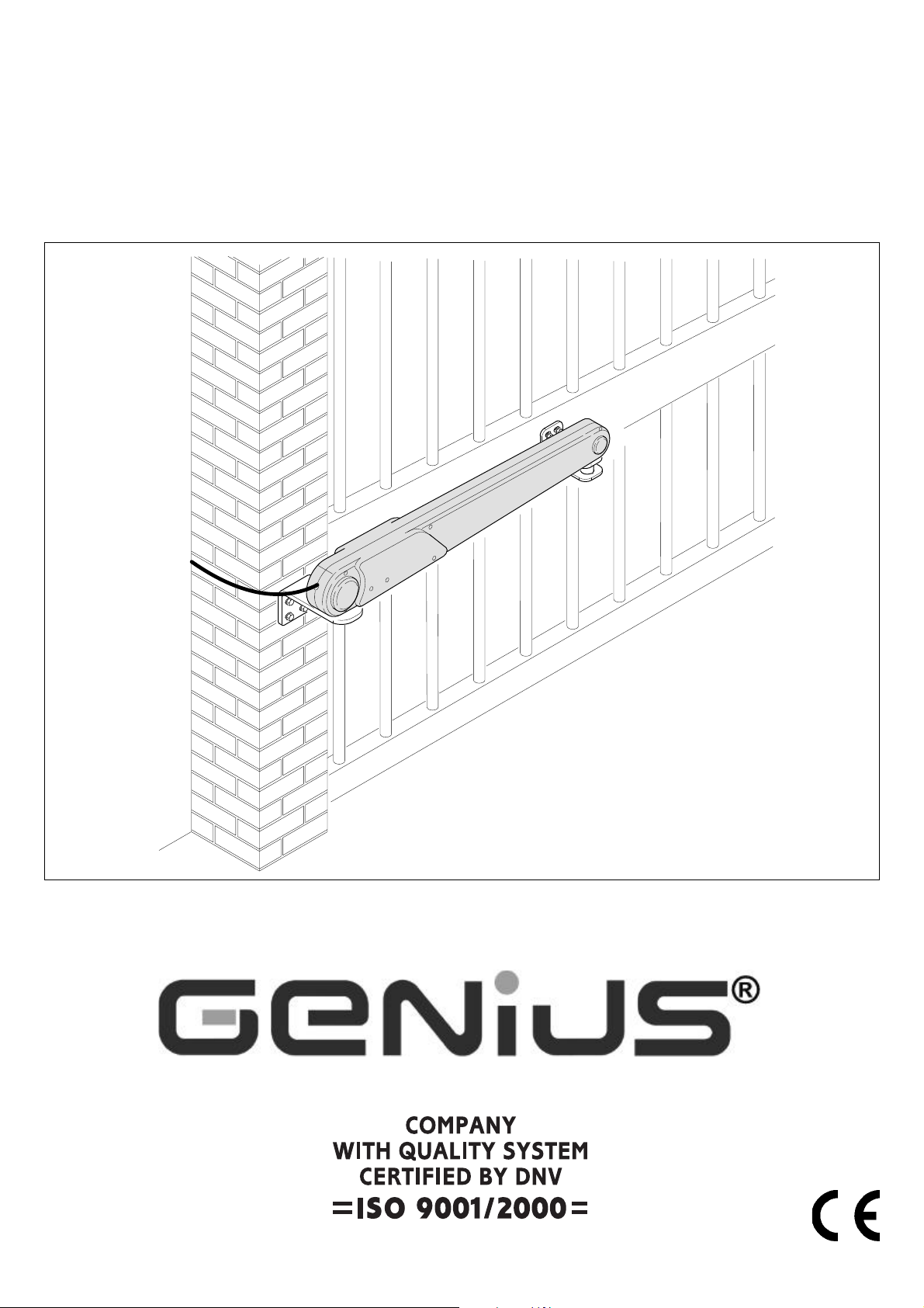
Action
Page 2

AVVERTENZE PER L’INSTALLATORE
1) ATTENZIONE! È importante per la sicurezza delle persone seguire attentamente tutta
l’istruzione. Una errata installazione o un errato uso del prodotto può portare a gravi danni
alle persone.
2)
Leggere attentamente le istruzioni prima di iniziare l’installazione del prodotto.
3) I materiali dell’imballaggio (plastica, polistirolo, ecc.) non devono essere lasciati alla
portata dei bambini in quanto potenziali fonti di pericolo.
4) Conservare le istruzioni per riferimenti futuri.
5) Questo prodotto è stato progettato e costruito esclusivamente per l’utilizzo indicato in
questa documentazione. Qualsiasi altro utilizzo non espressamente indicato potrebbe
pregiudicare l’integrità del prodotto e/o rappresentare fonte di pericolo.
6) GENIUS declina qualsiasi responsabilità derivata dall’uso improprio o diverso da quello per
cui l’automatismo è destinato.
7) Non installare l’apparecchio in atmosfera esplosiva: la presenza di gas o fumi infiammabili
costituisce un grave pericolo per la sicurezza.
8) Gli elementi costruttivi meccanici devono essere in accordo con quanto stabilito dalle
Norme EN 12604 e EN 12605.
Per i Paesi extra-CEE, oltre ai riferimenti normativi nazionali, per ottenere un livello di
sicurezza adeguato, devono essere seguite le Norme sopra riportate.
9) GENIUS non è responsabile dell’inosservanza della Buona Tecnica nella costruzione delle
chiusure da motorizzare, nonché delle deformazioni che dovessero intervenire nell’utilizzo.
10) L’installazione deve essere effettuata nell’osservanza delle Norme EN 12453 e EN 12445. Il
livello di sicurezza dell’automazione deve essere C+D.
11) Prima di effettuare qualsiasi intervento sull’impianto, togliere l’alimentazione elettrica e
scollegare le batterie.
12) Prevedere sulla rete di alimentazione dell’automazione un interruttore onnipolare con
distanza d’apertura dei contatti uguale o superiore a 3 mm. È consigliabile l’uso di un
magnetotermico da 6A con interruzione onnipolare.
13) Verificare che a monte dell’impianto vi sia un interruttore differenziale con soglia da 0,03
A.
14) Verificare che l’impianto di terra sia realizzato a regola d’arte e collegarvi le parti metalliche della chiusura.
15) L’automazione dispone di una sicurezza intrinseca antischiacciamento costituita da un
controllo di coppia. E' comunque necessario verificarne la sogli di intervento secondo
quanto previsto dalle Norme indicate al punto 10.
16) I dispositivi di sicurezza (norma EN 12978) permettono di proteggere eventuali aree di
pericolo da Rischi meccanici di movimento, come ad Es. schiacciamento, convogliamento,
cesoiamento.
17) Per ogni impianto è consigliato l’utilizzo di almeno una segnalazione luminosa nonché di
un cartello di segnalazione fissato adeguatamente sulla struttura dell’infisso, oltre ai
dispositivi citati al punto “16”.
18) GENIUS declina ogni responsabilità ai fini della sicurezza e del buon funzionamento
dell’automazione, in caso vengano utilizzati componenti dell’impianto non di produzione
GENIUS.
19) Per la manutenzione utilizzare esclusivamente parti originali GENIUS.
20) Non eseguire alcuna modifica sui componenti facenti parte del sistema d’automazione.
21) L’installatore deve fornire tutte le informazioni relative al funzionamento manuale del
sistema in caso di emergenza e consegnare all’Utente utilizzatore dell’impianto il libretto
d’avvertenze allegato al prodotto.
22) Non permettere ai bambini o persone di sostare nelle vicinanze del prodotto durante il
funzionamento.
23) Tenere fuori dalla portata dei bambini radiocomandi o qualsiasi altro datore di impulso, per
evitare che l’automazione possa essere azionata involontariamente.
24) Il transito tra le ante deve avvenire solo a cancello completamente aperto.
25) L’Utente utilizzatore deve astenersi da qualsiasi tentativo di riparazione o d’intervento
diretto e rivolgersi solo a personale qualificato.
26) Non mettere in corto circuito i poli delle batterie e non tentare di ricaricarle con alimentatori diversi dalle schede Master o Slave.
27) Non gettare le batterie esauste nei rifiuti ma smaltirle utilizzando gli appositi contenitori
per consentirne il riciclaggio. I costi di smaltimento sono già stati pagati dalla casa
costruttrice.
28) Tutto quello che non è previsto espressamente in queste istruzioni non è permesso
OBBLIGHI GENERALI PER LA SICUREZZA
IMPORTANT NOTICE FOR THE INSTALLER
1) ATTENTION! To ensure the safety of people, it is important that you read all the following
instructions. Incorrect installation or incorrect use of the product could cause serious
harm to people.
2) Carefully read the instructions before beginning to install the product.
3) Do not leave packing materials (plastic, polystyrene, etc.) within reach of children as
such materials are potential sources of danger.
4) Store these instructions for future reference.
5) This product was designed and built strictly for the use indicated in this documentation.
Any other use, not expressly indicated here, could compromise the good condition/
operation of the product and/or be a source of danger.
6) GENIUS declines all liability caused by improper use or use other than that for which the
automated system was intended.
7) Do not install the equipment in an explosive atmosphere: the presence of inflammable
gas or fumes is a serious danger to safety.
8) The mechanical parts must conform to the provisions of Standards EN 12604 and EN 12605.
For non-EU countries, to obtain an adequate level of safety, the Standards mentioned
above must be observed, in addition to national legal regulations.
9) GENIUS is not responsible for failure to observe Good Technique in the construction of the
closing elements to be motorised, or for any deformation that may occur during use.
10) The installation must conform to Standards EN 12453 and EN 12445. The safety level of the
automated system must be C+D.
11) Before attempting any job on the system, cut out electrical power and disconnect the
batteries.
12) The mains power supply of the automated system must be fitted with an all-pole switch
with contact opening distance of 3mm or greater. Use of a 6A thermal breaker with allpole circuit break is recommended.
13) Make sure that a differential switch with threshold of 0.03 A is fitted upstream of the system.
14) Make sure that the earthing system is perfectly constructed, and connect metal parts of
the means of the closure to it.
GENERAL SAFETY REGULATIONS
15) The automated system is supplied with an intrinsic anti-crushing safety device consisting
of a torque control. Nevertheless, its tripping threshold must be checked as specified in the
Standards indicated at point 10.
16) The safety devices (EN 12978 standard) protect any danger areas against mechanical
movement Risks, such as crushing, dragging, and shearing.
17) Use of at least one indicator-light is recommended for every system, as well as a warning
sign adequately secured to the frame structure, in addition to the devices mentioned at
point “16”.
18) GENIUS declines all liability as concerns safety and efficient operation of the automated
system, if system components not produced by GENIUS are used.
19) For maintenance, strictly use original parts by GENIUS.
20) Do not in any way modify the components of the automated system.
21) The installer shall supply all information concerning manual operation of the system in
case of an emergency, and shall hand over to the user the warnings handbook supplied
with the product.
22) Do not allow children or adults to stay near the product while it is operating.
23) Keep remote controls or other pulse generators away from children, to prevent the
automated system from being activated involuntarily.
24) Transit through the leaves is allowed only when the gate is fully open.
25) The user must not attempt any kind of repair or direct action whatever and contact
qualified personnel only.
26) Do not short-circuit the poles of the batteries and do not try to recharge the batteries with
power supply units other than Master or Slave cards.
27) Do not throw exhausted batteries into containers for other waste but dispose of them in
the appropriate containers to enable them to be recycled. Disposal costs have already
been paid for by the manufacturer.
28) Anything not expressly specified in these instructions is not permitted.
CONSIGNES POUR L'INSTALLATEUR
1) ATTENTION! Il est important, pour la sécurité des personnes, de suivre à la lettre toutes les
instructions. Une installation erronée ou un usage erroné du produit peut entraîner de
graves conséquences pour les personnes.
2) Lire attentivement les instructions avant d'installer le produit.
3) Les matériaux d'emballage (matière plastique, polystyrène, etc.) ne doivent pas être
laissés à la portée des enfants car ils constituent des sources potentielles de danger.
4) Conserver les instructions pour les références futures.
5) Ce produit a été conçu et construit exclusivement pour l'usage indiqué dans cette
documentation. Toute autre utilisation non expressément indiquée pourrait compromettre
l'intégrité du produit et/ou représenter une source de danger.
6) GENIUS décline toute responsabilité qui dériverait d'usage impropre ou différent de celui
auquel l'automatisme est destiné.
7) Ne pas installer l'appareil dans une atmosphère explosive: la présence de gaz ou de
fumées inflammables constitue un grave danger pour la sécurité.
8) Les composants mécaniques doivent répondre aux prescriptions des Normes EN 12604 et
EN 12605.
Pour les Pays extra-CEE, l'obtention d'un niveau de sécurité approprié exige non seulement
le respect des normes nationales, mais également le respect des Normes susmentionnées.
9) GENIUS n'est pas responsable du non-respect de la Bonne Technique dans la construction
des fermetures à motoriser, ni des déformations qui pourraient intervenir lors de l'utilisation.
10) L'installation doit être effectuée conformément aux Normes EN 12453 et EN 12445. Le
niveau de sécurité de l'automatisme doit être C+D.
11) Couper l'alimentation électrique et déconnecter la batterie avant toute intervention sur
l'installation.
12) Prévoir, sur le secteur d'alimentation de l'automatisme, un interrupteur omnipolaire avec
une distance d'ouverture des contacts égale ou supérieure à 3 mm. On recommande
d'utiliser un magnétothermique de 6A avec interruption omnipolaire.
13) Vérifier qu'il y ait, en amont de l'installation, un interrupteur différentiel avec un seuil de
0,03 A.
14) Vérifier que la mise à terre est réalisée selon les règles de l'art et y connecter les pièces
métalliques de la fermeture.
15) L'automatisme dispose d'une sécurité intrinsèque anti-écrasement, formée d'un contrôle
du couple. Il est toutefois nécessaire d'en vérifier le seuil d'intervention suivant les
prescriptions des Normes indiquées au point 10.
16) Les dispositifs de sécurité (norme EN 12978) permettent de protéger des zones
éventuellement dangereuses contre les Risques mécaniques du mouvement, comme
l'écrasement, l'acheminement, le cisaillement.
17) On recommande que toute installation soit doté au moins d'une signalisation lumineuse,
d'un panneau de signalisation fixé, de manière appropriée, sur la structure de la fermeture,
ainsi que des dispositifs cités au point “16”.
18) GENIUS décline toute responsabilité quant à la sécurité et au bon fonctionnement de
l'automatisme si les composants utilisés dans l'installation n'appartiennent pas à la
production GENIUS.
19) Utiliser exclusivement, pour l'entretien, des pièces GENIUS originales.
20) Ne jamais modifier les composants faisant partie du système d'automatisme.
21) L'installateur doit fournir toutes les informations relatives au fonctionnement manuel du
système en cas d'urgence et remettre à l'Usager qui utilise l'installation les "Instructions
pour l'Usager" fournies avec le produit.
22) Interdire aux enfants ou aux tiers de stationner près du produit durant le fonctionnement.
23) Eloigner de la portée des enfants les radiocommandes ou tout autre générateur d'impulsions,
pour éviter tout actionnement involontaire de l'automatisme.
24) Le transit entre les vantaux ne doit avoir lieu que lorsque le portail est complètement
ouvert.
25) L'Usager qui utilise l'installation doit éviter toute tentative de réparation ou d'intervention
directe et s'adresser uniquement à un personnel qualifié.
26) Ne pas mettre en court-circuit les pôles des batteries et ne pas tenter de les recharger avec
d'autres platines d'alimentation que les platines Maître ou Esclave.
27) Ne pas jeter les batteries épuisées à la poubelle, mais les éliminer dans les conteneurs
spécifiques pour le recyclage. Les coûts d'élimination des déchets ont déjà été payés par
le constructeur.
28) Tout ce qui n'est pas prévu expressément dans ces instructions est interdit.
RÈGLES DE SÉCURITÉ
Page 3
ACTION Automated system
ENGLISH
These instructions apply to the following model:
ACTION
The ACTION automated system automates residential swing-leaf
gates with leaves of up to 1.8 m in length.
It consists of non-reversing electro-mechanical linear operators,
powered by a 12 Vdc battery, each coupled to a control board
recharging the battery. The SLAVE equipment (required on 2-leaf
gates only) is controlled by the MASTER equipment to which all
accessories and pulse generators are connected. The MASTER
card can be programmed and is used to set the following:
function logics, work times (by self-learning) and pause times, leaf
speed, and the sensitivity of the anti-crushing device.
The non-reversing system guarantees the gate will automatically
lock when the motor is not operating. A release system enables
the gate to be moved by hand in case of trouble.
The ACTION automated system was designed and built for
controlling vehicle access. Do not use for any other purpose.
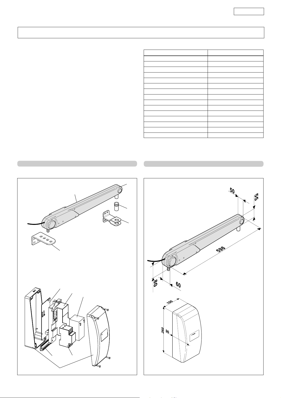
1. DESCRIPTION AND TECHNICAL SPECIFICATIONS
TAB. 1 TECHNICAL SPECIFICATIONS OF ACTION OPERATOR
MODEL ACTION
Power supply 12Vdc
Rated absorbed power (W) 48
Max static force (N) 1700
Load-free linear speed (cm./sec.) 3,2
Rod effective stroke 280 mm
Use frequency (cycles/hour) 5
Consecutive cycles on charged battery max. 15
Battery recharge time 10' for each completed cycle
Operating ambient temperature -20 ÷ +55 °C
Operator Weight (kg) 2,2
Protection class IP 44
Leaf maximum length (m) 1.80
Leaf max weight (kg) 250
Operator overall dimensions LxHxD (mm) see fig. 2
Length of operator power cable 0,7 m
2. DIMENSIONS
햷
햳
햲
햲햲
햲 Action operator
햲햲
햳햳
햳 Rear fitting
햳햳
햴햴
햴 Front fitting
햴햴
햵햵
햵 Release
햵햵
햶햶
햶 Bracket bush
햶햶
햷햷
햷 Control board
햷햷
햸햸
햸 Board support
햸햸
햹햹
햹 Battery
햹햹
햺햺
햺 Terminal board (Master only)
햺햺
햻햻
햻 Transformer (Optional item)
햻햻
햽햽
햽 Enclosure in class IP 55
햽햽
햸
햹
햵
햶
ACTION
OPERATOR
햴
햺
햽
햻
CONTROL
BOARD
ENCLOSURE
Fig. 1 Fig. 2
• Dimensions in mm
13
Page 4
ENGLISH
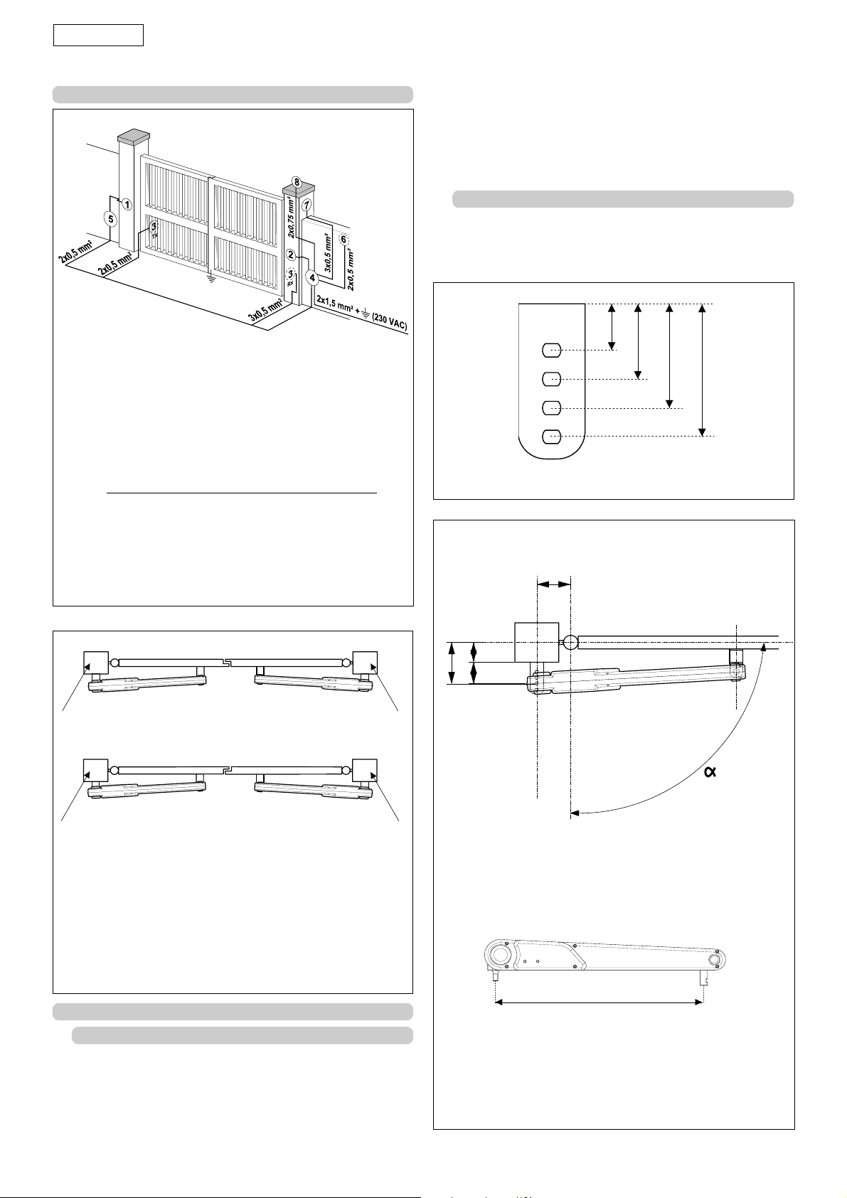
3. ELECTRONIC EQUIPMENT (standard system)
햲햲
햲 Action operator
햲햲
햳햳
햳 Action operator
햳햳
햴햴
햴 Photocells
햴햴
햵햵
햵 MASTER control board (controls all accessories)
햵햵
햶햶
햶 SLAVE control board (for 2nd leaf only)
햶햶
햷햷
햷 Key operated push-button
햷햷
햸햸
햸 Receiver
햸햸
햹햹
햹 12 Vdc flashing lamp
햹햹
Notes:1)Do not extend the operator connecting cables
2)To lay electric cables, use adequate rigid and/or
flexible tubes.
3)Always separate low voltage connection cables from
those operating at 230 Vac. To prevent any interference
whatever, use separate sheaths.
Fig. 3
to those indicated in the technical specifications.
• Make sure that the leaves move uniformly and correctly,
without any irregular friction during their entire travel.
• Make sure that the hinges are in good condition.
• Check if the mechanical stops of the limit-switches are fitted.
We advise you to have any metalwork carried out before the
automated system is installed.
4.2. INSTALLATION DIMENSIONS
There are 4 possible installation dimensions Z as shown in figure 5.
There is no need to cut the rear bracket to obtain dimension A.
Establish the installation position of the operator by referring to Fig.
6 and to table 2.
42
68
94
120
• Dimensions in mm
Fig. 5
B
Leaf 1 Leaf 2
Master card
Master card
Leaf 2
Leaf 1
Slave card
Slave card
In double-leaf applications, the Master card always
commands leaf 1. In case of incorrect electrical set-up, leaf 1
can be commanded by the Slave card, and leaf 2 by the
Master card. For programming, refer to chapter 13.
Leaf 1 is always the leaf that starts first on opening and is
delayed on closing.
Fig. 4
4. INSTALLING THE AUTOMATED SYSTEM
4.1. PRELIMINARY CHECKS
To ensure safety and an efficiently operating automated system,
make sure the following conditions are observed:
• The structure of the gate must be suitable for being
automated. In particular, check that the structure is sufficiently
strong and rigid, and that its dimensions and weight conform
D
A
Z
Z= see fig.5
• Dimensions in mm
520
Fig. 6
14
Page 5

120 ÷ 126
ENGLISH
B
90°
114 ÷ 119
108 ÷ 113
98 ÷ 102 103 ÷ 107
100°
90°
100°
90°
100°
90°
90°100°
100° 90°
90°
90°
100°
90°
100°
Tab.2
92 ÷ 97
88 ÷ 91
30 ÷ 39
40 ÷ 49
90°
50 ÷ 59
60 ÷ 69
100°
70 ÷ 79
90°
80 ÷ 89
D
90 ÷ 99
90°
100 ÷ 109
110 ÷ 119
100°
120 ÷ 129
90°
130 ÷ 140
15
Page 6
ENGLISH
To select the dimensions, we advise you to measure dimension D
and then, referring to table 2, determine dimension B. The hole for
the rear fitting (dimension Z) to be used is the one obtained from
the intersection of dimensions B and D, as shown in bold in table
2. The table shows all combinations of the B, D and Z dimensions
that can be used, with the relevant opening angles. The white
boxes indicate the non permissible dimensions.
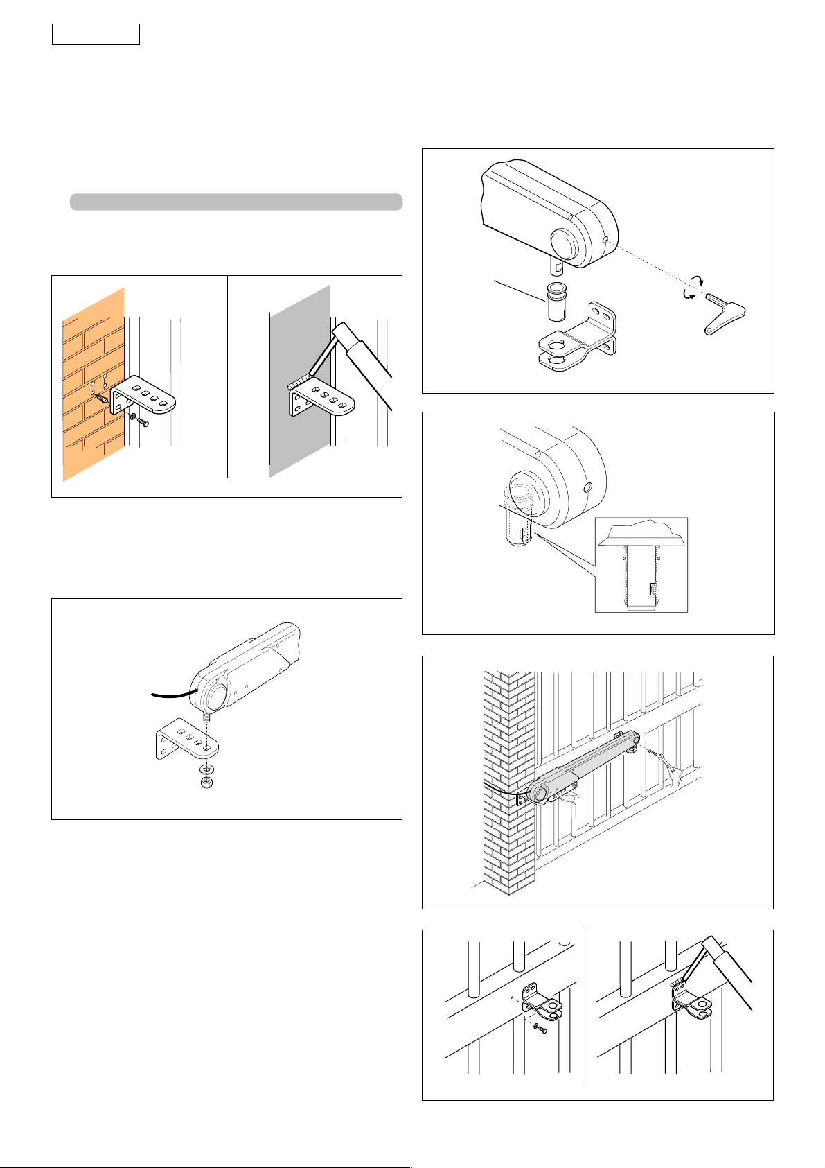
4.3. INSTALLATION STEPS
•Secure the rear fitting to the pillar by welding or using suitable
expansion plugs (Fig. 7) and ensuring it is perfectly horizontal.
•The fitting can be either welded directly on the leaf, or screwed
on, using the threaded inserts (Fig. 12).
IMPORTANT: the operator is non-reversing, so do not, on any
account, try to move the leaves by hand.
BLOCCA
LOCK
BLOQUE
BLOQUEAR
SBLOCCA
UNLOCK
DEBLOQUE
DESBLOQUEAR
ENTRIEGELT
DEBLOKKEREN
VERRIEGELT
BLOKKEREN
Fig. 9
Fig. 7
•Secure the operator to the rear fitting, with the nut and washer
(Fig.8), taking care to correctly fit the chamfered part of the pin
in the hole of the rear fitting.
Fig. 8
•NB.: the operator is supplied with a travel limit pin on the closed
leaf position. If necessary, use the manual release (see chpt. 16),
to take the operator pin to the closed position (the pin must be
on the stop position on the front of the operator) - see fig.9.
•Turn the release key anti-clockwise for 5 turns as shown in figure
9.
•Insert the bracket bush (fig.9 ref.1)in the front fitting (fig.9). Insert
the operator so that the groove of the pin coincides with the
mechanical stop on the bush (fig. 10).
•Turn the release key clockwise until the pin returns to the closing
stop position.
•Turn the release key anti-clockwise for 3 turns.
•Find the securing position of the front fitting on the leaf; make
sure that the operator and fitting are perfectly horizontal
(fig.11).
Fig. 10
Fig. 11
16
Fig. 12
Page 7
ENGLISH
MIND MASTER AND MIND SLAVE CONTROL BOARDS
5. WARNINGS
Important: Before attempting any job on the control boards (connections, maintenance), cut out electrical power and the support
batteries.
- Install, upstream of the system, a differential thermal breaker with adequate tripping threshold.
- Always separate 230VAC power cable from control and safety cables (push-buttons receiver, photocells, etc.). To avoid any
electrical noise, use separate sheaths or a shielded cable (with earthed shield).
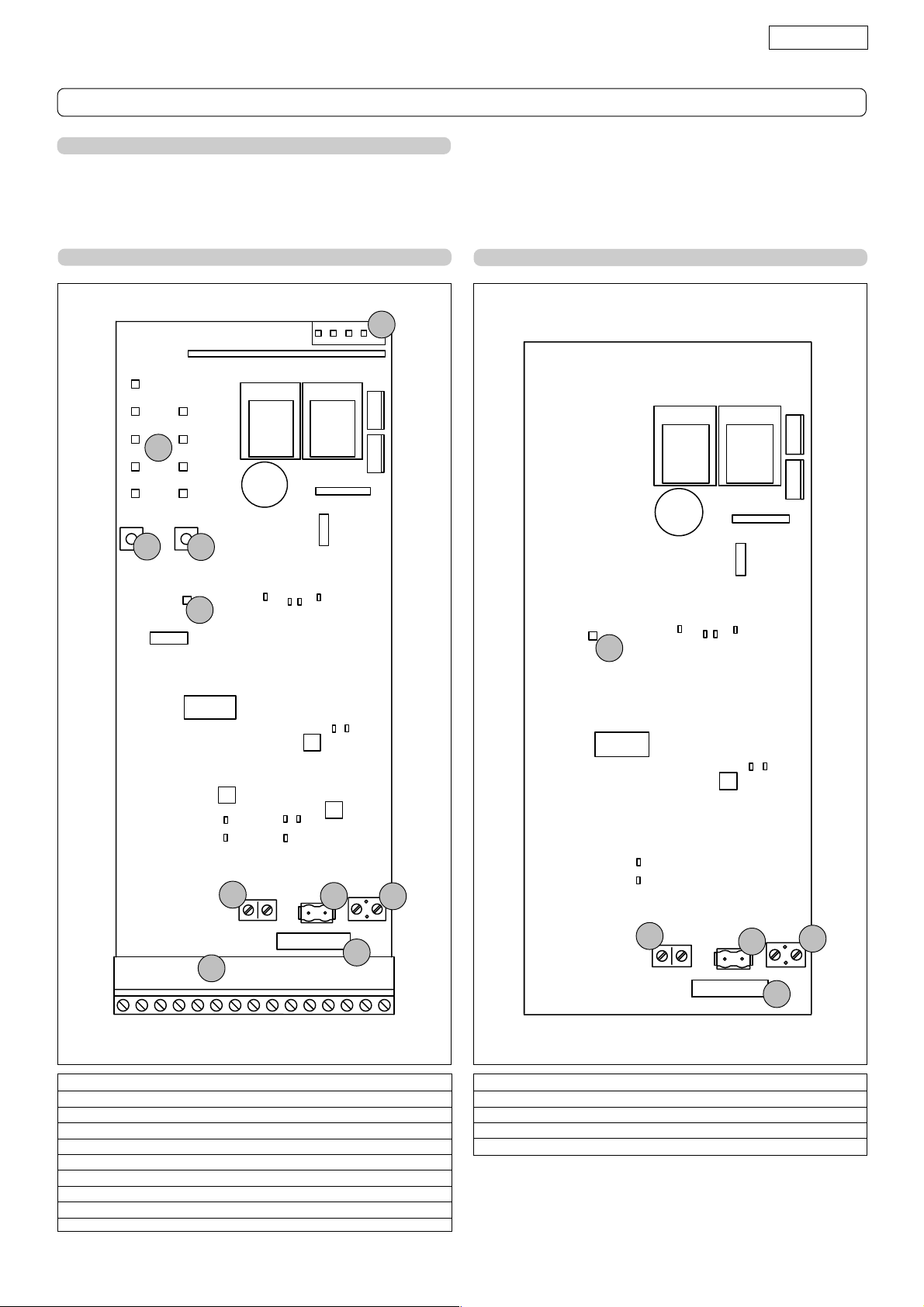
6. LAY-OUT OF MASTER CARD COMPONENTS
J5
J5
RL2
RL1
LED
P1
SW2
P2
SW1
P
7. LAY-OUT OF SLAVE CARD COMPONENTS
RL2
RL1
P
J2
J2
1
J1
J4
J4
F1J1 WIRING
J3
J3
F1
15
Fig. 13
LED Programming LEDs
P Power ON and diagnostics LED
P1 "Function" programming push-button
P2 "Value" programming push-button
F1 Battery and motor fuse - F15A
J1 Accessories Terminal board
J2 Transformer Terminal board
J3 Motor connection terminal board
J4 Battery connector
J5 Minidec connector/RP Receiver
J2
J2
1
P Power ON and diagnostics LED
F1 Battery and motor fuse - F15A
J2 Bus connection terminal board
J3 Motor connection terminal board
J4 Battery connector
J4
J4
F1J1 WIRING
F1
17
J3
J3
15
Fig. 14
Page 8
ENGLISH
8. MASTER AND SLAVE CARDS COMMON
CHARACTERISTICS
Batteries hermetic Pb 12Vdc 1.2Ah - dimensions 96x46x50
Enclosure protection class IP 55
Absorbed power 16 VA
Motor max current 15A
Operating ambient temperature -20° +55°
Protection fuses N° 1 (see fig. 13 and 14)
Anti-crushing function Encoder - Current control
9. SLAVE CARD TECHNICAL SPECIFICATIONS
Power supply from Master
Terminal board outputs Motor - Battery - Bus
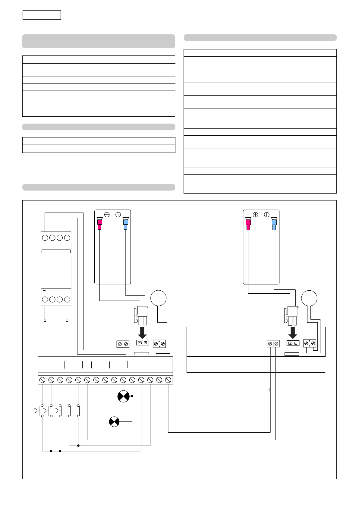
11. ELECTRIC CONNECTIONS
10. MASTER CARD TECHNICAL SPECIFICATIONS
Power supply 12Vac
Transformer characteristics Primary 230 Vac - Secondary
12 Vac - 16VA
Accessories max. load at 24 Vdc 150 mA
Rapid connector max load 50 mA
Function logics Automatic / "Stepped" Automatic /
Safety device / “Stepped” semi-automatic
Opening/closing time By self-learning
Pause time Programmable: 5, 10, 20, 30 sec.
Leaf delay time when opening and closing
(op 0s, cl 0s) - (op 2s, cl 2s) - (op 2s, cl 4s) - (op 2s, cl 8s)
Speed Selectable on 4 levels
Static force adjustment Selectable on 4 levels
Terminal board inputs Open - Open released leaf
Stop - Safety devices at opng. - Safety devices at clsng.
Terminal board outputs Flashing lamp - Motor - Bus -
indicator-light - Accessories
24 Vdc - 12 Vdc power supply
Rapid connector Minidec cards - RP cards
Programmable functions Logic - pause time - leaf opening
and closing delay - anti-crushing force - operators speed
12 Vac
5
7
6
1
2
3
230Vac
50 HZ
Master card
J1 WIRING
A
OPEN
3
B
STP
1152
8
4
OP
4
FSW
56
CL
BUS
J2
8
910
7
++
W.L.
+24V
LAMP
F1
11 12
+
12Vdc
M1
BROWN
J3
J4
13
14
---
BLUE
-
Slave card
J1 WIRING
1
M2
BLUE
BROWN
J2
F1
BUS
J3
J4
15
*
12Vdc
0,5W
*
Example of connection without photocells
12Vdc
21W
Fig. 15
18
Page 9
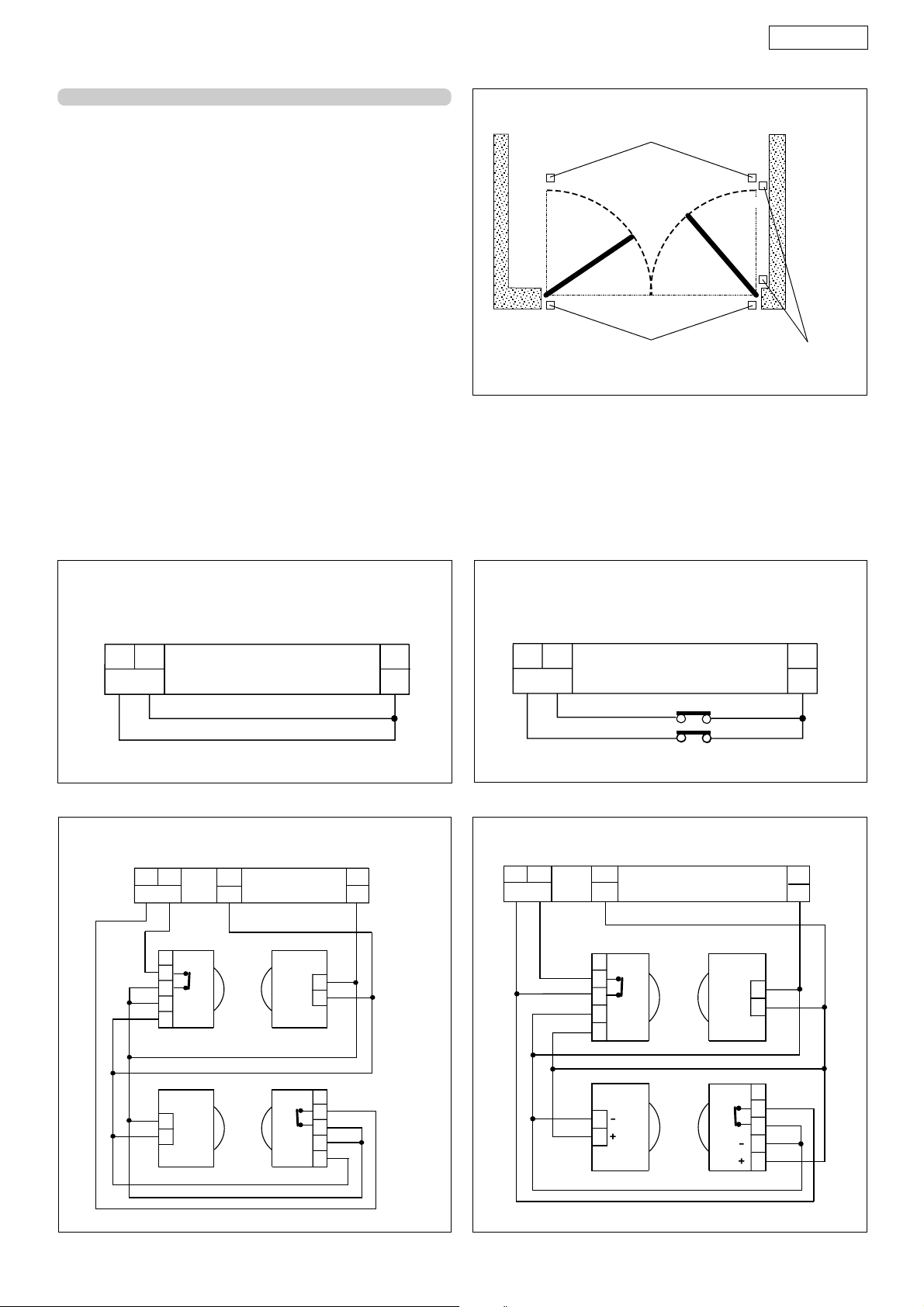
11.1. Connection of photocells and safety devices
ENGLISH
Before connecting the photocells (or other devices) we advise
you to select the type of operation according to the
movement zone to be protected (see fig.16).
Opening safety devices: they operate only during the gate
opening movement and, therefore,
they are suitable for protecting the
zone between the opening leaves
and fixed obstacles (walls, etc)
against the risk of impact and
crushing.
Closing safety devices: they operate only during the gate
closing movement and, therefore,
are suitable for protecting the closing
zone against the risk of impact.
Opening/closing safety devices: they operate during the
gate opening and closing
movements and, therefore, they are
suitable for protecting the opening
and closing zones against the risk of
impact.
N.B.: If one or more devices have the same function (opening
or closing), they must be connected to each other in series.
N.C. contacts must be used.
Application examples
Commonly used wiring lay-outs:
Opening/closing safety devices
Closing safety devices
Opening safety devices
Fig. 16
Connection of no safety device
4 5
FSW
12
Fig. 17
Connection of a pair of photocells, one for opening
and the other for closing
4 5
FSW
1
2
3
4
5
RX CL TX CL
7
+
12
–
1
2
Connection of a safety device for closing
and a safety device for opening
4 5
FSW
12
Connection of a pair of photocells, one for closing
and one for opening /closing
4 5
FSW
7
+
RX CL TX CL
1
2
3
4
-
+
5
12
—
1
-
+
2
Fig. 18
1
1
2
2
3
4
5
RX OPTX OP
1
2
TX OP/CL
RX OP/CL
Fig.19
1
2
3
4
5
Fig. 20
19
Page 10
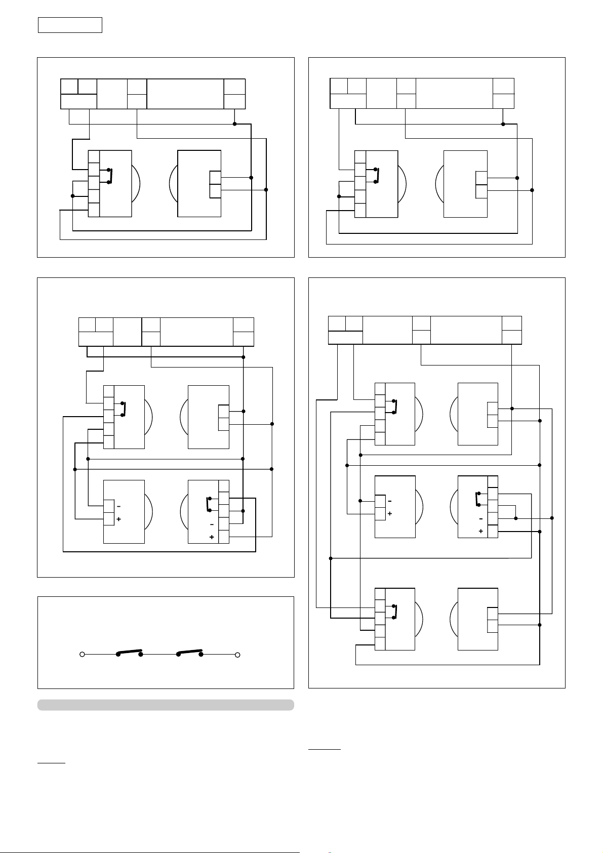
ENGLISH
Connection of 1 pair of photocells for closing
4
FSW
5
7
+
1
2
3
4
5
12
—
1
2
RX TX
Connection of 2 pairs of photocells for closing
4 5
FSW
7
+
12
—
Fig. 21
Connection of 1 pair of photocells for opening
4
FSW
5
7
+
1
2
3
4
5
12
—
1
2
RX TX
Fig. 22
Connection of a pair of closing photocells, one for opening
4 5
and the other for opening/closing
7
FSW
+
12
—
RX CL1
1
2
3
4
5
TX CL2
1
2
-
+
TX CL1
-
+
RX CL2
1
2
1
2
3
4
5
Connection of 2 N.C. contacts in series
(E.g. Photocells, Stop)
Fig. 23
RX CL TX CL
1
2
3
4
-
+
5
1
2
TX OP/CL
RX OP TX OP
1
2
3
4
-
+
5
RX OP/CL
1
-
+
2
1
2
3
4
5
1
-
+
2
11.2. J1 TERMINAL BOARD - ACCESSORIES
J1 Terminal board for Master Card - Accessories (fig. 15 )
Low voltage terminal board used for connecting all
accessories.
24 Vdc
– Negative for powering accessories (terminals 12,13,14,15)
+ Positive for powering accessories + 24 Vdc (terminals 7
and 8)
Important: The maximum load of the accessories powered at
Fig. 24
Fig. 25
24 Vdc is 150 mA.
accessories are not powered.
When the automated system is idle, the
To calculate absorption values,
refer to the instructions for individual accessories.
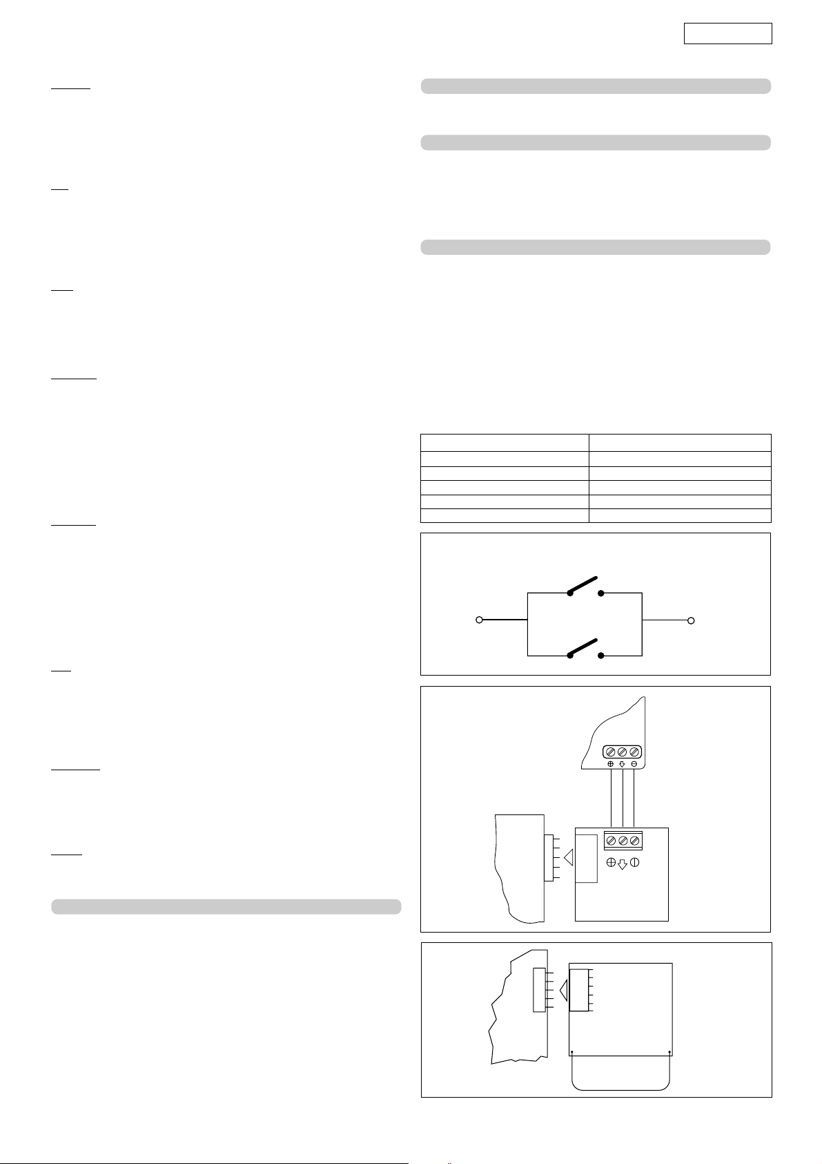
OPEN A - "TOTAL OPENING" (terminal 1) OPEN command: any
device (e.g. push-button) which, by closing a contact,
provides an opening and/or closing pulse for both gate
leaves.
To install several opening pulse generators, connect the N.O.
contacts in parallel (see fig. 26).
20
Page 11
ENGLISH
OPEN B - "RELEASED LEAF OPENING" (terminal 2) OPEN command:
any device (e.g. push-button) which, by closing a contact,
provides an opening and/or closing pulse for the gate leaf
activated by the Master Card.
To install several opening pulse generators, connect the N.O.
contacts in parallel (fig. 26).
STP - STOP Command (terminal 3): any device (e.g.: push-button)
which, by opening a contact, stops gate movement.
To install several stop devices, connect the N.C. contacts in
series (fig.24).
NB.: If STOP devices are not connected, jumper connect the
inputs STP and -.
FSW
All devices (photocells, sensitive edges, magnetic loops) with
N.C. (normally closed) contact, which, if there is an obstacle
in the area they protect, operate to interrupt gate leaf
movement (fig. 16).
FSW OP. - Opening safety devices contact (terminal 4): during
opening, the safety devices reverse motion to closing. They
do not operate during closing.
If the Opening safety devices are tripped when the gate is
closed, they prevent the leaf opening movement.
NB.: If no opening safety devices are connected, jumper
connect inputs OP and - (fig. 17).
The purpose of the opening safety devices is to safeguard the
zone behind the gate leaves (fig. 16).
FSW CL. - Closing safety devices contact (terminal 5): during
closing, the safety devices reverse motion to opening. They
do not operate during opening .
If the Closing safety devices are tripped when the gate is
open, they prevent the leaf closing movement.
NB.: If no closing safety devices are connected, jumper
connect inputs CL and - (fig. 17).
The purpose of the closing safety devices is to safeguard the
leaf movement area during closing (fig. 16).
11.4. J3 Terminal board - Motor Connection
This terminal board is used for connecting the motor (see fig.
15). For wire colours, refer to fig. 15.
11.5. J4 Connector - Battery connection
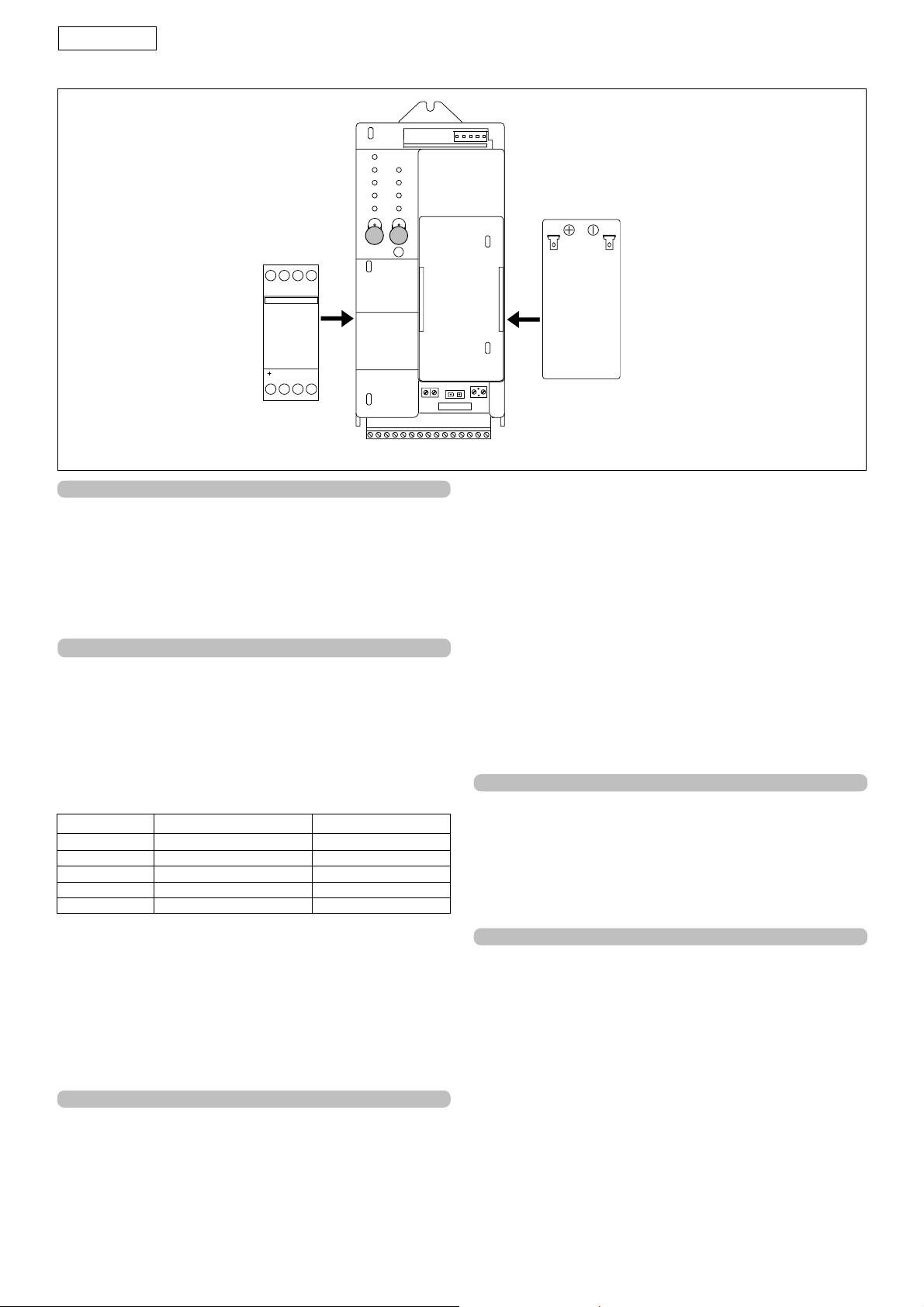
Connect the operator support battery (fig. 15) to this
connector. The battery is housed as shown in figure 29.
N.B.: The batteries are not supplied fully charged; however,
the charge is sufficient for programming and setting-up the
system.
11.6. J5 Connector - Quick-fit for Minidec and Rp - 12 Vdc
This is used for rapid connection of the Minidec cards and RP
receivers.
IMPORTANT: do not use Decoder cards on the quick-fit
connection.
In case of a mains power cut, this connector is powered for
twelve hours - after this time, the opening push-buttons
(terminals 1 and 2) are the only active commands.
The connector is powered down to store sufficient energy for
running some emergency manoeuvres in the space of 30
days.
Tab. 3
Gate status Indicator-light status
Closed Light Off
Open - Open in pause status Lighted
Closing Flashing
Opening Lighted
Blocked Lighted
Connection of 2 N.O. contacts in parallel
(E.g. Open A, Open B)
BUS - (terminal 6): Connection between the master and slave
equipment. The Bus connection supplies the current for
charging the slave card battery and enables
communication between the two equipment (terminals 6
and 15 of the master card - connector J2 of the slave card).
To connect, use 2 wires with diameter of 0.5 mm2 or greater.
W. LIGHT - (terminals 9 and 11): Power supply for the indicator-
light, 12 Vdc 0.5 W max. (terminals 9 and 11). To avoid
compromising correct operation of the system, do not exceed
the indicated power. For instructions on operation of the
indicator- light, consult table 3.
LAMP - (terminals 10 and 11): Flashing lamp output, 12 Vdc 21 W.
BA15S lamp. To avoid compromising correct operation of the
system, do not exceed the indicated power.
11.3. J2 Terminal board
It is used for connecting the transformer (optional item), 12
Vac 16 VA. Place the transformer in its compartment, as
shown in figure 29, and make the connection as shown in
figure 15. Alternatively, the transformer can be remotely
located up to a distance of 100 mt from the equipment, using
wires with a diameter of 0.5 mm
2.
Master
Card
Master
Card
Fig. 26
PLUS
MINIDEC
Fig. 27
RP
21
Fig. 28
Page 12
ENGLISH
56
12
78
34
E
D
4
C
3
B
2
A
1
P1
P2
J3
J4 Battery
J2 Transf.
F1 Batt.
Motor
15
Fig. 29
12. Diagnostics
The “P” LED (see fig. 21) has a diagnostic function. There are
4 LED statuses.
•Steady light indicating mains power ON and battery charged.
•Flashing slowly ( lights every second ), indicates no mains
power but battery charged
•Flashing quickly ( lights every 250 msec. ) indicates mains
power ON but discharged battery
•Light OFF indicates no mains power and discharged battery.
13. Status of inputs
The equipment has a function for checking the status of the
inputs on the terminal board.
This is how to access the function:
In the all LEDs OFF status (both LEDs with letters and numbers),
press push-button P2 – the status of the inputs will be shown
in the LED columns with letters and numbers, as shown in table
4.
Tab.4
Led ON OFF
A = Open A Command active Command inactive
B = Open B Command active Command inactive
C = Stop Command inactive Command active
D = Fsw o p Safety devices disabled
E = Fsw cl Safety devices disabled
Safety devices enabled
Safety devices enabled
When you have finished checking, press push-button P2
again to exit the inputs status function.
N.B.: The LEDs status check function stays active for 5 minutes and
then the board returns to all LEDs OFF status.
WARNING : When you access the inputs status function, all
accessories are powered, even with the gate idle. Pushbutton P1 is active and can be used as Open A.
14. PROGRAMMING
To access the "PROGRAMMING" mode, press pushbuttons P1 and P2 (fig. 29). The 5 programming functions
are indicated by LEDs with letters, whereas the modifiable
values are indicated by numbered LEDs.
Push-button P1 is used to select the function to be
programmed.
Push-button P2 is used to modify the value of the
selected function.
- If you press push-button P1, LED A lights up; use pushbutton P2 to select the required logic as shown in table 5.
-If you press push-button P1 again, LED B lights up; use
push-button P2 to select the required pause times (for
logics A, AP and S only) as shown in table 5.
-If you press push-button P1 again, LED C lights up; use
push-button P2 to select the required leaf delays as
shown in table 5.
-If you press push-button P1 again, LED D lights up;
use push-button P2 to select the static force of the
operators as shown in table 5.
-If you press push-button P1 again, LED E lights up; use
push-button P2 to select the speed of the operators as
shown in table 5.
-If you press push-button P1 again, the five LEDs light up
steadily to indicate access to the learning function. There
are two learning modes: simple and complete. The travel
limit stops are essential for simple learning.
•Simple learning
By using just one command, this procedure enables selflearning of work times and decelerations. Make sure that
the leaves are closed.
While the 5 function LEDs are lighted steadily, briefly press
(about 1 second) the P2 push-button - the operators
start the opening manoeuvre, and the function LEDs
begin flashing; Wait for the operators to reach the
opening stops. The learning procedure has finished.
•Complete learning
This procedure is used to define the deceleration and
stop points of the operators. The procedure differs
depending on whether the gate is single leaf or double
leaf. Make sure that the leaves are closed.
Procedure for double-leaf gate
While the 5 function LEDs are lighted steadily, hold down
push-button P2 for about 3 seconds - operator 1 (master)
starts the opening manoeuvre; the following functions
are commanded either by open pulses A (e.g. keyoperated push-button, radio control) or by the P2 push-
button:
1st OPEN - Leaf 1 opening deceleration start.
2nd OPEN - Leaf 1 opening stop and start of leaf 2
opening movement.
22
Page 13
ENGLISH
As an alternative to the open, allow the leaf to reach its
opening stop point.
3rd OPEN - Leaf 2 opening deceleration start.
4th OPEN - Leaf 2 opening stop and immediate start of
leaf 2 closing movement. As an alternative to the open,
allow the leaf to reach its opening stop point.
5th OPEN - Leaf 2 closing deceleration stop.
When the leaf has reached its closing stop point, the
closing movement of leaf 1 starts immediately.
6th OPEN - Leaf 1 closing deceleration start. Allow the
leaf to reach its closing stop point.
The learning procedure has finished.
Procedure for single-leaf gate
While the function 5 LEDs are lighted steadily, hold down
push-button P2 for about 3 seconds - operator 1 (master)
starts the opening manoeuvre; the following functions
are commanded either by open pulses A (e.g. keyoperated push-button, radio control) or by the P2 pushbutton:
1st OPEN - Leaf deceleration start.
2nd OPEN - Leaf opening stop (alternatively, allow the
leaf to reach its opening stop point) and immediate
closing reverse.
3rd OPEN - Leaf deceleration start. Allow the leaf to
reach its closing stop point.
The learning procedure has finished.
Controlling leaf 1 with either Master or Slave card
With this function, you can select the leaf you wish to
move with the Master card.
Press and hold down push-button P1, then press pushbutton P2. LED A starts flashing. Using push-button P2,
move from LED 1 to LED2 according to the type of leaf
control you require, as described below:
-LED 1 lighted: the Master card commands leaf 1
(Default).
LED 2 lighted: the Master card commands leaf 2.
NOTE: the operation of the Slave card is automatically
set, according to how the Master card was
programmed.
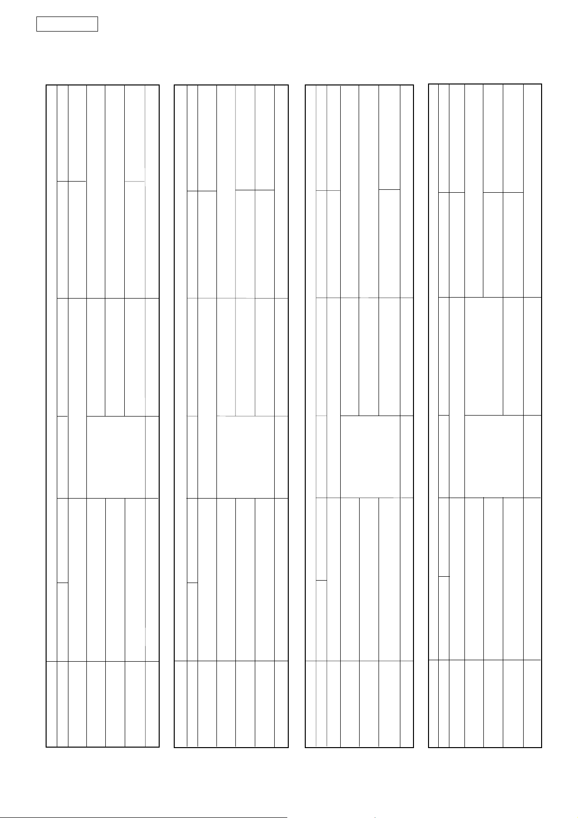
Table 5
Programming
LED Function
A Function logic
(see tables 6/a, 6/b, 6/c and 6/d)
1 = A (automatic)
2 = S (safety)
3 = AP (stepped automatic)
4 = EP (stepped semi-automatic) (Default)
B Pause times
1 = 5 seconds (Default)
2 = 10 seconds
3 = 20 seconds
4 = 30 seconds
C Opening / Closing delays
1 = op 0 sec./cl 0 sec.
2 = op 2 sec./cl 2 sec.
3 = op 2 sec./cl 4 sec. (Default)
4 = op 2 sec./cl 8 sec.
D Static force
1 = low
2 = medium low
3 = medium high (Default)
4 = high
E Speed
1 = low
2 = medium low (Default)
3 = medium high
4 = high
15. AUTOMATION TEST
When installation has been completed, run a careful
functional check of the automated system and all
accessories connected to it, especially the safety devices.
Hand the "User's guide" page to the Customer, and explain
correct operation and use of the operator.
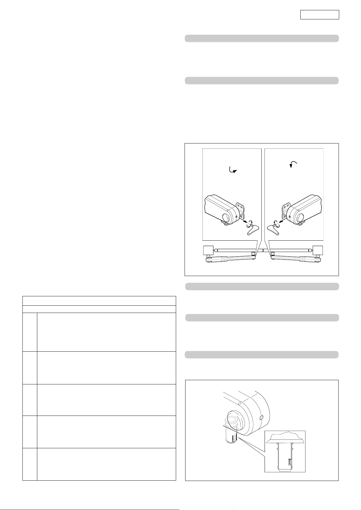
16. MANUAL OPERATION
If the gate has to be moved manually due to a fault of the
automated system, use the release device as follows:
•Fit the supplied Allen wrench in the front part of the
operator and turn it clockwise for 5 turns (fig. 30).
•Lift the operator by its front end, detaching it from the
fitting.
UNLOCK
17. RESTORING NORMAL OPERATION MODE
•Re-position the operator on the front fitting so that the
groove of the pin coincides with the mechanical stop on the
bush (fig. 31).
18. MAINTENANCE
Carry out the following jobs at least every six months:
•Check if the anti-crushing device is correctly adjusted.
•Check the efficiency of the release system.
•Check the efficiency of safety devices and accessories.
19. REPAIRS
For any repairs, contact the authorised Repair Centres.
23
UNLOCK
Fig. 30
Fig. 31
Page 14
ENGLISH
OP/CLS. SAFETY DEVICE
No effect (OPEN disabled)
immediately
Inverts movement
No effect
(OPEN disabled)
OP/CLS. SAFETY DEVICECLOSING SAFETY DEVICESOPENING SAFETY DEVICES
Inverts movement immediately
Inverts movement immediately
PEN disabled)
immediately
OP/CLS. SAFETY DEVICE
No effect (O
Inverts movement
OP/CLS. SAFETY DEVICE
PEN disabled)
No effect (OPEN disabled)
Inverts movement immediately
Re-loads pause time
No effect
Locks and, on release, reverses at opening
CLOSING SAFETY DEVICESOPENING SAFETY DEVICES
No effect
No effect
PULSES
No effect (OPEN disabled)
STOP
Stops operation
No effect (OPEN disabled)
No effect
No effect
No effect
PULSES
Inverts movement immediately
No effect (OPEN disabled)
P
No effect
STO
Closes after 5" (OPEN disabled)
Inverts movement immediately
No effect
No effect
No effect (OPEN disabled)
No effect
No effect
PULSES
Inverts movement immediately
Stops operation
No effect
Re-loads pause time
No effect (O
PEN disabled)
SAFETY DEVICES
Inverts movement immediately
No effect
SING
No effect (O
CLO
No effect
No effect
No effect
to close at release
Locks and reverses
OPENING SAFETY DEVICES
No effect (OPEN disabled)
STOP
Stops operation
No effect
No effect (OPEN disabled)
No effect
CLOSING SAFETY DEVICESOPENING SAFETY DEVICES
Inverts movement immediately Inverts movement immediately
No effect
PULSES
Inverts movement immediately
No effect (OPEN disabled) No eff ect
STOP
Stops operation
No effect (OPEN disabled)
)
PEN
o effect
N
ust open, it disables O
(if it m
No effect
(OPEN disabled)
OPEN-A OPEN B
GATE STATUS
LOGIC "A"
Tab. 6/a
No effect
Re-loads pause time
Re-opens the leaf/ves immediately
Opens leaf/ves and re-closes after pause time
CLOSED
AT CLOSING
OPEN on PAUSE
Closes the leaf/ves
LOCKED
AT OPENING
Tab. 6/b
Opens leaf/ves and re-closes after pause time
OPEN-A OPEN B
"S"
CLOSED
IC
GATE STATUS
G
LO
Closes the leaf/ves
Re-closes the leaf/ves immediately
Re-closes the leaf/ves immediately
Re-opens the leaf/ves immediately
OPEN-A OPEN B
AT CLOSING
OPEN on PAUSE
LOCKED
AT OPENING
Tab. 6/c
GATE STATUS
LOGIC "AP"
24
Stops operation
Opens leaf/ves and re-closes after pause time
CLOSED
OPEN on PAUSE
Stops operation
Closes the leaf/ves
Re-opens the leaf/ves immediately
LOCKED
AT OPENING
AT CLOSING
Tab. 6/d
Opens leaf/ves
Re-closes the leaf/ves immediately
OPEN-A OPEN B
CLOSED
GATE STATUS
LOGIC "EP"
Stops operation
OPEN
AT CLOSING
Stops operation
Restarts moving in reverse direction
LOCKED
AT OPENING
Page 15
DICHIARAZIONE CE DI CONFORMITÁ PER MACCHINE
(DIRETTIVA 89/392 CEE, ALLEGATO II, PARTE B)
Fabbricante: GENIUS s.r.l.
Indirizzo: Via Padre Elzi, 32
Dichiara che: L'Attuatore mod. ACTION
• è costruito per essere incorporato in una macchina o
• è conforme ai requisiti essenziali di sicurezza
e inoltre dichiara che non è consentito mettere in servizio il
macchinario fino a che la macchina in cui sarà incorporata o
di cui diverrà componente sia stata identificata e ne sia stata
dichiarata la conformità alle condizioni della Direttiva 89/392/
CEE e successive modifiche trasposta nella legislazione
nazionale dal DPR n° 459 del 24 Luglio 1996.
Grassobbio, 1 Marzo 2002
24050 - Grassobbio
BERGAMO - ITALIA
per essere assemblato con altri macchinari per
costituire una macchina ai sensi della Direttiva 89/
392/CEE, e successive modifiche 91/368/CEE, 93/44/
CEE, 93/68/CEE;
delle seguenti altre direttive CEE:
73/23/CEE e successiva modifica 93/68/CEE.
89/336 CEE e successiva modifica 92/31/CEE e
93/68/CEE
L’Amministratore Delegato
D. Gianantoni
EC MACHINE DIRECTIVE COMPLIANCE DECLARATION
(DIRECTIVE 89/392 EEC, APPENDIX II, PART B)
Manufacturer: GENIUS s.r.l.
Address: Via Padre Elzi, 32
Hereby declares that: the ACTION
• is intended to be incorporated into machinery, or to
• complies with the essential safety requirements in the
and furthermore declares that unit must not be put into service
until the machinery into which it is incorporated or of which it
is a component has been identified and declared to be in
conformity with the provisions of Directive 89/392 ECC and
subsequent amendments enacted by the national
implementing legislation.
Grassobbio, 1 March 2002
24050 - Grassobbio
BERGAMO - ITALY
be assembled with other machinery to constitute
machinery in compliance with the requirements of
Directive 89/392 EEC, and subsequent amendments
91/368 EEC, 93/44 EEC and 93/68 EEC;
following EEC Directives:
73/23 EEC and subsequent amendment 93/68 EEC.
89/336 EEC and subsequent amendments 92/31 EEC
and 93/68 EEC.
Managing Director
D. Gianantoni
DÉCLARATION CE DE CONFORMITÉ
(DIRECTIVE EUROPÉENNE "MACHINES" 89/392/CEE,
ANNEXE II, PARTIE B)
Fabricant: GENIUS s.r.l.
Adresse:
Déclare d’une part
et d’autre part
qu’il est formellement interdit de mettre en fonction l'automatisme en
question avant que la machine dans laquelle il sera intégrée ou dont
il constituera un composant ait été identifiée et déclarée conforme
aux exigences essentielles de la directive européenne "machines"
89/392/CEE, et décrets de transposition de la directive.
Grassobbio, le 1 Mars 2002
Via Padre Elzi, 32
24050 - Grassobbio
BERGAMO - ITALIE
que l'automatisme mod. ACTION
• est prévue soit pour être incorporée dans une machine,
soit pour être assemblée avec d’autres composants ou
parties en vue de former une machine selon la directive
européenne "machines" 89/392 CEE, modifiée 91/368
CEE, 93/44 CEE, 93/68 CEE.
• satisfait les exigences essentielles de sécurité des
directives CEE suivantes:
73/23 CEE, modifiée 93/68 CEE.
89/336 CEE, modifiée 92/31 CEE et 93/68 CEE.
L’Administrateur Délégué
D. Gianantoni
DECLARACIÓN DE CONFORMIDAD CE PARA MÁQUINAS
(DIRECTIVA 89/392 CEE, ANEXO II, PARTE B)
Fabricante: GENIUS s.r.l.
Dirección: Via Padre Elzi, 32
Declara que: El equipo automático mod. ACTION
Asimismo, declara que no está permitido poner en marcha el
equipo si la máquina en la cual será incorporado, o de la cual
se convertirá en un componente, no ha sido identificada o no
ha sido declarada su conformidad a lo establecido por la
Directiva 89/392 CEE y sus sucesivas modificaciones, y a la ley
que la incorpora en la legislación nacional.
Grassobbio, 1º de Marzo de 2002.
24050 - Grassobbio
BERGAMO - ITALIA
• Ha sido construido para ser incorporado en una
máquina, o para ser ensamblado con otros
mecanismos a fin de constituir una máquina con
arreglo a la Directiva 89/392 CEE y a sus sucesivas
modificaciones 91/368 CEE, 93/44 CEE y 93/68 CEE.
• Cumple los requisitos esenciales de seguridad
establecidos por las siguientes directivas CEE:
73/23 CEE y sucesiva modificación 93/68 CEE,
89/336 CEE y sucesivas modificaciones 92/31 CEE y
93/68 CEE.
Administrador Delegado
D. Gianantoni
GENIUS s.r.l.
Via Padre Elzi, 32
24050 - Grassobbio
BERGAMO-ITALY
tel. 0039.035.4242511
fax. 0039.035.4242600
[email protected]
www.geniusg.com
EG-KONFORMITÄTSERKLÄRUNG ZU MASCHINEN
(gemäß EG-Richtlinie 89/392/EWG, Anhang II, Teil B)
Hersteller: GENIUS s.r.l.
Adresse: Via Padre Elzi, 32
erklärt hiermit, daß: der Antrieb Mod. ACTION
und erklärt außerdem, daß die Inbetriebnahme solange
untersagt ist, bis die Maschine, in welche diese Maschine
eingebaut wird oder von der sie ein Bestandteil ist, den
Bestimmungen der Richtlinie 89/392 EWG sowie deren
nachträglichen Änderungen entspricht.
Grassobbio, 1 März 2002
24050 - Grassobbio
BERGAMO - ITALIEN
• zum Einbau in eine Maschine oder mit anderen
Maschinen zu einer Maschine im Sinne der Richtlinie
89/392 EWG und deren Änderungen 91/368 EWG,
93/44 EWG, 93/68 EWG vorgesehen ist.
• den wesentlichen Sicherheitsbestimmungen
folgender anderer EG-Richtlinien entspricht:
73/23 EWG und nachträgliche Änderung 93/68 EWG
89/336 EWG und nachträgliche Änderung 92/31 EWG
sowie 93/68 EWG
Der Geschäftsführer
D. Gianantoni
Le descrizioni e le illustrazioni del presente manuale non sono impegnative. GENIUS si riserva il diritto, lasciando inalterate
le caratteristiche essenziali dell’apparecchiatura, di apportare in qualunque momento e senza impegnarsi ad
aggiornare la presente pubblicazione, le modifiche che essa ritiene convenienti per miglioramenti tecnici o per qualsiasi
altra esigenza di carattere costruttivo o commerciale.
The descriptions and illustrations contained in the present manual are not binding. GENIUS reserves the right, whils leaving
the main features of the equipments unaltered, to undertake any modifications to holds necessary for either technical
or commercial reasons, at any time and without revising the present publication.
Les descriptions et les illustrations du présent manuel sont fournies à titre indicatif. GENIUS se réserve le droit d’apporter
à tout moment les modifications qu’elle jugera utiles sur ce produit tout en conservant les caractéristiques essentielles,
sans devoir pour autant mettre à jour cette publication.
Las descripciones y las ilustraciones de este manual no comportan compromiso alguno. GENIUS se reserva el derecho,
dejando inmutadas las características esenciales de los aparatos, de aportar, en cualquier momento y sin comprometerse
a poner al día la presente publicación, todas las modificaciones que considere oportunas para el perfeccionamiento
técnico o para cualquier otro tipo de exigencia de carácter constructivo o comercial.
Die Beschreibungen und Abbildungen in vorliegendem Handbuch sind unverbindlich. GENIUS behält sich das Recht vor,
ohne die wesentlichen Eigenschaften dieses Gerätes zu verändern und ohne Verbindlichkeiten in Bezung auf die
Neufassung der vorliegenden Anleitungen, technisch bzw, konstruktiv / kommerziell bedingte Verbesserungen
vorzunehmen.
De beschrijvingen en illustraties in deze handleiding zijn niet bindend. GENIUS behoudt zich het recht voor om op elk
willekeurig moment, en zonder verplicht te zijn deze publicatie bij te werken, de wijzigingen aan te brengen die wenselijk
geacht worden met het oog op technische verbeteringen of om andere redenen van technische of commerciële aard,
waarbij de essentiële eigenschappen van de apparatuur ongewijzigd blijven.
Timbro rivenditore:
Distributor’s stamp:
Timbre de l’agent:
Sello del revendedor:
Fachhändlerstempel:
Stempel van de dealer:
CE VERKLARING VAN OVEREENSTEMMING VOOR
MACHINES
(RICHTLIJN 89/392/EEG, BIJLAGE II, DEEL B)
Fabrikant: GENIUS s.r.l.
Adres: Via Padre Elzi, 32
verklaart dat: de aandrijving mod. ACTION
en verklaart bovendien dat het niet is toegestaan de machine
in bedrijf te stellen voordat de machine waarin zij wordt
opgenomen of waarvan zij onderdeel wordt, geïdentificeerd
is, en de overeenkomstigheid ervan verklaard is volgens de
voorwaarden van de Richtlijn 89/392/EEG en latere wijzigingen,
die in de nationale wetgeving zijn omgezet door het
Presidentieel Besluit nr. 459 van 24 juli 1996.
Grassobbio, 1 Maart 2002
24050 - Grassobbio
BERGAMO - ITALIE
• is gebouwd voor opname in een machine of voor
assemblage met andere machines, met het doel een
machine te vormen in de zin van de Richtlijn 89/392/
EEG en latere wijzigingen 91/368/EEG, 93/44/EEG, 93/
68/EEG;
• in overeenstemming is met de fundamentele
veiligheidseisen van de volgende EEG-richtlijnen:
73/23/EEG en latere wijziging 93/68/EEG.
89/336/EEG en latere wijziging 92/31/EEG en 93/68/EEG
President - directeur
D. Gianantoni
I0146 REV.0
 Loading...