

Page 1

Operator's Manual
Serial Number Range
Z®-45J
from Z4525F-62000
ANSI/CSA
North America
South America
Asia
DC Power
Bi-Energy Power
with
Maintenance
Information
Original Instructions
Fifth Edition
First Printing
Part No. 1297032GT
Page 2

Operator's Manual Fifth Edition • First Printing
Z®-45J DC • Z®-45J Bi-Energy Part No. 1297032GT
Front Matter
Contents
Introduction ............................................................1
Symbol and Hazard Pictorials Definitions ..............7
General Safety .................................................... 10
Personal Safety ................................................... 18
Work Area Safety ................................................ 19
Legend ................................................................ 28
Controls ............................................................... 29
Inspections .......................................................... 36
Operating Instructions ......................................... 54
Transport and Lifting Instructions ....................... 63
Maintenance ....................................................... 66
Specifications ...................................................... 69
Copyright © 1999 Terex Corporation
Fifth Edition: First Printing, April 2020
Genie and "Z" are registered trademarks of Terex South
Dakota, Inc. in the U.S.A. and many other countries.
These machines comply with
ANSI/SAIA A92.20
CAN/CSA B354.6
Page 3

Fifth Edition • First Printing Operator's Manual
Introduction
Part No. 1297032GT Z®-45J DC • Z®-45J Bi-Energy 1
Introduction
About this manual
Genie appreciates your choice of our machine for
your application. Our number one priority is user
safety, which is best achieved by our joint efforts.
This book is an operation and daily maintenance
manual for the user or operator of a Genie
machine.
This manual should be considered a permanent
part of your machine and should remain with the
machine at all times. If you have any questions,
contact Genie.
Product Identification
The machine serial number is located on the serial
label.
Serial number stamped
on chassis
Serial label
(located under cover)
Intended Use and Familiarization
Guide
The intended use of this machine is to lift
personnel, including tools, and materials to an
aerial work site. Before operating the machine, it’s
the operator’s responsibility to read and
understand this familiarization guide.
Each person must be trained to operate a
Mobile Elevating Work Platform (MEWP).
Familiarization with the MEWP must be given
to each person who is authorized, competent
and trained.
Only trained and authorized personnel should
be permitted to operate the machine.
The operator is responsible to read,
understand, and obey the manufacturer’s
instructions and safety rules provided in the
Operator’s Manual.
The Operator’s Manual is located in the
manual storage container, at the platform.
For specific product applications, see
Contacting The Manufacturer.
Page 4

Operator's Manual Fifth Edition • First Printing
Introduction
2 Z®-45J DC • Z®-45J Bi-Energy Part No. 1297032GT
Platform controls symbology and related
machine movement:
Platform level
Platform rotate
Jib boom up/down
Primary boom up/down
Turntable rotate
Primary boom extend/retract
Secondary boom up/down
Drive forward/reverse
Steer right/left
Page 5

Fifth Edition • First Printing Operator's Manual
Introduction
Part No. 1297032GT Z®-45J DC • Z®-45J Bi-Energy 3
Ground controls symbology and related
machine movement:
Platform level
Platform rotate
Jib boom up/down
Primary boom up/down
Turntable rotate
Primary boom extend/retract
Secondary boom up/down
Sequential functions and movement:
Drive and steer.
Interlocked functions:
Elevated drive speed.
Elevated drive in an off-level condition.
Drive enable when the boom is rotated past the
non-steer wheels.
All platform and ground controls.
Limitations of use:
The intended use of this machine is to lift
personnel, including tools, and materials to an
aerial work site.
Do not elevate the platform unless the machine
is on firm level ground.
Stability enhancing means:
Foam filled tires
Restricted operating envelope:
500 lbs/227 kg platform capacity.
Page 6

Operator's Manual Fifth Edition • First Printing
Introduction
4 Z®-45J DC • Z®-45J Bi-Energy Part No. 1297032GT
Bulletin Distribution and
Compliance
Safety of product users is of paramount
importance to Genie. Various bulletins are used by
Genie to communicate important safety and
product information to dealers and machine
owners.
The information contained in the bulletins is tied to
specific machines using the machine model and
serial number.
Distribution of bulletins is based on the most
current owner on record along with their
associated dealer, so it is important to register
your machine and keep your contact information
up to date.
To ensure safety of personnel and the reliable
continued operation of your machine, be sure to
comply with the action indicated in a respective
bulletin.
To view any open bulletins for your machine, visit
us on the web at www.genielift.com.
Contacting the Manufacturer
At times it may be necessary to contact Genie.
When you do, be ready to supply the model
number and serial number of your machine, along
with your name and contact information. At
minimum, Genie should be contacted for:
Accident reporting
Questions regarding product applications and
safety
Standards and regulatory compliance information
Current owner updates, such as changes in
machine ownership or changes in your contact
information. See Transfer of Ownership, below.
Transfer of Machine Ownership
Taking a few minutes to update owner information
will ensure that you receive important safety,
maintenance and operating information that
applies to your machine.
Please register your machine by visiting us on the
web at www.genielift.com or by calling us toll free
at 1-800-536-1800.
Page 7

Fifth Edition • First Printing Operator's Manual
Introduction
Part No. 1297032GT Z®-45J DC • Z®-45J Bi-Energy 5
Danger
Failure to obey the instructions and
safety rules in this manual will result
in death or serious injury.
Do Not Operate Unless:
You learn and practice the principles of safe
machine operation contained in this operator’s
manual.
1 Avoid hazardous situations.
Know and understand the safety rules
before going on to the next section.
2 Always perform a pre-operation inspection.
3 Always perform function tests prior to use.
4 Inspect the workplace.
5 Only use the machine as it was intended.
You read, understand and obey the
manufacturer’s instructions and safety rules—
safety and operator’s manuals and machine
decals.
You read, understand and obey employer’s
safety rules and worksite regulations.
You read, understand and obey all applicable
governmental regulations.
You are properly trained to safely operate the
machine.
Safety Sign Maintenance
Replace any missing or damaged safety signs.
Keep operator safety in mind at all times. Use mild
soap and water to clean safety signs. Do not use
solvent-based cleaners because they may
damage the safety sign material.
Page 8

Operator's Manual Fifth Edition • First Printing
Introduction
6 Z®-45J DC • Z®-45J Bi-Energy Part No. 1297032GT
Hazard Classification
Decals on this machine use symbols, color coding,
and signal words to identify the following:
Safety alert symbol—used to alert
you to potential personal injury
hazards. Obey all safety
messages that follow this symbol
to avoid possible injury or death.
Indicates a hazardous situation
which, if not avoided, will result in
death or serious injury.
Indicates a hazardous situation
which, if not avoided, could result
in death or serious injury.
Indicates a hazardous situation
which, if not avoided, could result
in minor or moderate injury.
Indicates a property damage
message.
Page 9
Fifth Edition • First Printing Operator's Manual
Symbol and Hazard Pictorials Definitions
Part No. 1297032GT Z®-45J DC • Z®-45J Bi-Energy 7
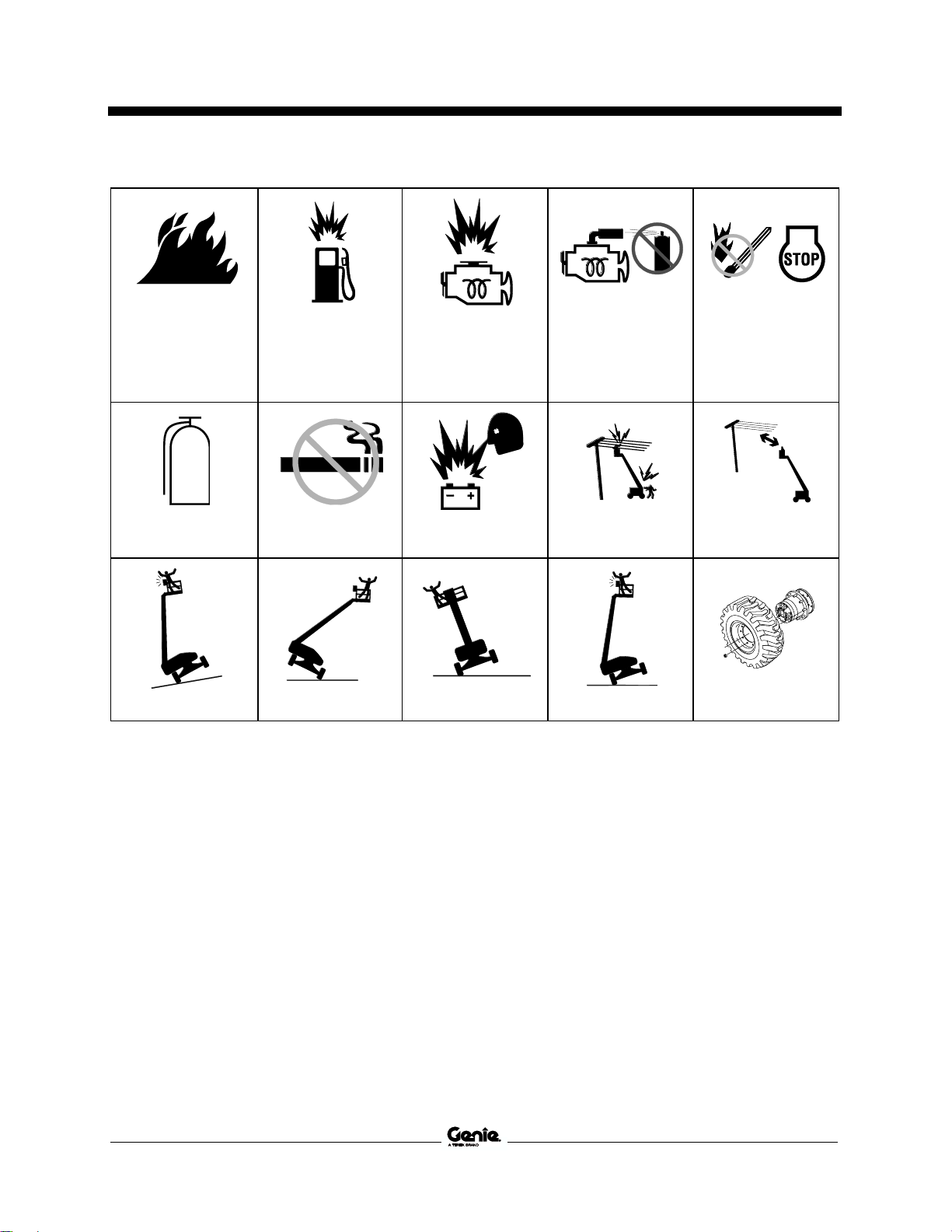
Symbol and Hazard Pictorials Definitions
Fire hazard
Explosion hazard
Explosion hazard
Do not use ether or
other high energy
starting aids on
machines equipped
with glow plugs.
No smoking.
No flame.
Stop engine.
Fire extinguisher
No smoking
Explosion hazard
Electrocution hazard
Maintain required
clearance
Tip-over hazard
Tip-over hazard
Tip-over hazard
Tip-over hazard
Tire specifications
Page 10

Operator's Manual Fifth Edition • First Printing
Symbol and Hazard Pictorials Definitions
8 Z®-45J DC • Z®-45J Bi-Energy Part No. 1297032GT
Wheel load
Wind speed
Maximum capacity
Manual force
Support the platform
or boom during
maintenance
Tie-down point
Lifting point
Platform tie-down
instructions
Lifting & tie down
instructions
Lanyard anchorage
points
Corrosive acid.
Color coded direction
arrows
Runaway hazard
Collision hazard
Overhead obstruction
Page 11

Fifth Edition • First Printing Operator's Manual
Symbol and Hazard Pictorials Definitions
Part No. 1297032GT Z®-45J DC • Z®-45J Bi-Energy 9
Electrocution hazard
Avoid contact
Disconnect battery
Voltage rating for
power to platform
Pressure rating for air
line to platform
Recovery procedure if tilt alarm sounds while
elevated.
Platform uphill:
1 Lower primary.
2 Lower secondary.
3 Retract primary.
Platform downhill:
1 Retract primary.
2 Lower secondary.
3 Lower primary.
Read the operator’s
manual
Access by trained
and authorized
personnel only
Read the service
manual
Emergency lowering
Crush hazard
Page 12

Operator's Manual Fifth Edition • First Printing
General Safety
10 Z®-45J DC • Z®-45J Bi-Energy Part No. 1297032GT
General Safety
Page 13

Fifth Edition • First Printing Operator's Manual
General Safety
Part No. 1297032GT Z®-45J DC • Z®-45J Bi-Energy 11
Page 14

Operator's Manual Fifth Edition • First Printing
General Safety
12 Z®-45J DC • Z®-45J Bi-Energy Part No. 1297032GT
Page 15

Fifth Edition • First Printing Operator's Manual
General Safety
Part No. 1297032GT Z®-45J DC • Z®-45J Bi-Energy 13
* These decals are model, option or configuration specific.
Page 16

Operator's Manual Fifth Edition • First Printing
General Safety
14 Z®-45J DC • Z®-45J Bi-Energy Part No. 1297032GT
Page 17

Fifth Edition • First Printing Operator's Manual
General Safety
Part No. 1297032GT Z®-45J DC • Z®-45J Bi-Energy 15
Page 18

Operator's Manual Fifth Edition • First Printing
General Safety
16 Z®-45J DC • Z®-45J Bi-Energy Part No. 1297032GT
Page 19

Fifth Edition • First Printing Operator's Manual
General Safety
Part No. 1297032GT Z®-45J DC • Z®-45J Bi-Energy 17
* These decals are model, option or configuration specific.
Page 20

Operator's Manual Fifth Edition • First Printing
Personal Safety
18 Z®-45J DC • Z®-45J Bi-Energy Part No. 1297032GT
Personal Safety
Personal Fall Protection
Personal fall protection equipment (PFPE) is
required when operating this machine.
Occupants must wear a safety belt or harness in
accordance with governmental regulations. Attach
the lanyard to the anchor provided in the platform.
Operators must comply with employer, job site and
governmental rules regarding the use of personal
protective equipment.
All PFPE must comply with applicable
governmental regulations, and must be inspected
and used in accordance with the PFPE
manufacturer’s instructions.
Page 21

Fifth Edition • First Printing Operator's Manual
Work Area Safety
Part No. 1297032GT Z®-45J DC • Z®-45J Bi-Energy 19
Work Area Safety
Electrocution Hazards
This machine is not electrically insulated and will
not provide protection from contact with or
proximity to electrical current.
Obey all local and
governmental regulations
regarding required
clearance from electrical
power lines. At a minimum,
the required clearance
contained in the chart
below must be followed.
Line Voltage
Required Clearance
0 to 50KV
10 ft
3.05 m
50 to 200KV
15 ft
4.60 m
200 to 350KV
20 ft
6.10 m
350 to 500KV
25 ft
7.62 m
500 to 750KV
35 ft
10.67 m
750 to 1000KV
45 ft
13.72 m
Allow for platform movement, electrical line sway
or sag, and beware of strong or gusty winds.
Keep away from the
machine if it contacts
energized power lines.
Personnel on the ground
or in the platform must
not touch or operate the
machine until energized
power lines are shut off.
Do not operate the machine during lightning or
storms.
Do not use the machine as a ground for welding.
Tip-over Hazards
Occupants, equipment and materials shall not
exceed the maximum platform capacity.
Maximum platform capacity
500 lbs
227 kg
Maximum platform capacity
Machine equipped with
Aircraft Protection Package
440 lbs
200 kg
Maximum occupants
2
The weight of options and accessories, such as
pipe cradles, panel cradles and welders, will
reduce the rated platform capacity and must be
subtracted from the platform capacity. See the
decals with the options and accessories.
If using accessories, read, understand and obey
the decals, instructions and manuals with the
accessory.
Do not alter or disable the limit switches.
Page 22

Operator's Manual Fifth Edition • First Printing
Work Area Safety
20 Z®-45J DC • Z®-45J Bi-Energy Part No. 1297032GT
Do not use air-filled tires. These machines are
equipped with foam-filled tires. Wheel weight and
proper counterweight configuration are critical to
stability.
Do not raise or extend the
boom unless the machine
is on a firm, level surface.
Do not depend on the tilt alarm as a level indicator.
The tilt alarm sounds in the platform only when the
machine is on a severe slope.
If the tilt alarm sounds while the boom is lowered:
Do not extend, rotate or raise the boom above
horizontal. Move the machine to a firm, level
surface before raising the platform.
If the tilt alarm sounds when the platform is raised,
use extreme caution. The Machine Not Level
indicator light will come on and the drive function
in one or both directions will not operate. Identify
the condition of the boom on the slope as shown
below. Follow the steps to lower the boom before
moving to a firm, level surface. Do not rotate the
boom while lowering.
If the tilt alarm sounds
with the platform uphill:
1 Lower the primary
boom.
2 Lower the
secondary boom.
3 Retract the primary
boom.
If the tilt alarm sounds
with the platform
downhill:
1 Retract the primary
boom.
2 Lower the
secondary boom.
3 Lower the primary
boom.
Do not operate the machine in strong or gusty
winds. Do not increase the surface area of the
platform or the load. Increasing the area exposed
to the wind will decrease machine stability.
Page 23

Fifth Edition • First Printing Operator's Manual
Work Area Safety
Part No. 1297032GT Z®-45J DC • Z®-45J Bi-Energy 21
Do not raise the boom
when wind speeds may
exceed 28 mph/12.5 m/s.
If wind speeds exceed
28 mph/12.5 m/s when
the boom is raised, lower
the boom and do not
continue to operate the
machine.
Use extreme care and
slow speeds while driving
the machine in the
stowed position across
uneven terrain, debris,
unstable or slippery
surfaces and near holes
and drop-offs.
Do not drive the machine on or near uneven
terrain, unstable surfaces or other hazardous
conditions with the boom raised or extended.
Do not push off or pull
toward any object outside
of the platform.
Maximum allowable side
force – 90 lbs/400 N
Do not alter or disable machine components that
in any way affect safety and stability.
Do not replace items critical to machine stability
with items of different weight or specification.
Do not modify or alter a mobile elevating work
platform without prior written permission from the
manufacturer. Mounting attachments for holding
tools or other materials onto the platform,
toeboards, or guard rail system can increase the
weight in the platform and the surface area of the
platform or the load.
Do not place or attach
fixed or overhanging loads
to any part of this
machine.
Do not place ladders or
scaffolds in the platform or
against any part of this
machine.
Do not transport tools and materials unless they
are evenly distributed and can be safely handled
by person(s) in the platform.
Do not use the machine on a moving or mobile
surface or vehicle.
Be sure the tires are in good condition and the lug
nuts tightened.
Do not use the platform controls to free a platform
that is caught, snagged, or otherwise prevented
from normal motion by an adjacent structure. All
personnel must be removed from the platform
before attempting to free the platform using the
ground controls.
Page 24

Operator's Manual Fifth Edition • First Printing
Work Area Safety
22 Z®-45J DC • Z®-45J Bi-Energy Part No. 1297032GT
Do not use batteries that weigh less than the
original equipment. Batteries are used as
counterweight and are critical to machine stability.
Each battery must weigh a minimum of 105 lbs /
47.6 kg. Each battery box including batteries must
weigh a minimum of 530 lbs / 240.4 kg.
Do not use the machine as a crane.
Do not push the machine or other objects with the
boom.
Do not contact adjacent structures with the boom.
Do not tie the boom or platform to adjacent
structures.
Do not place loads outside the platform perimeter.
Operation on Slopes Hazards
Do not drive the machine on a slope that exceeds
the maximum uphill, downhill or side slope rating
of the machine. Slope rating applies only to
machines in the stowed position.
Maximum slope rating, stowed position
Platform downhill
30%
(17°)
Platform uphill
20%
(11°)
Side slope
25%
(14°)
Note: Slope rating is subject to ground conditions
with one person in the platform and adequate
traction. Additional platform weight may reduce
slope rating. See Driving on a Slope in the
Operating Instructions section.
Fall Hazards
Occupants must wear a
safety belt or harness in
accordance with
governmental regulations.
Attach the lanyard to the
anchor provided in the
platform.
Do not sit, stand, or climb
on the platform guard rails.
Maintain a firm footing on
the platform floor at all
times.
Do not climb down from the
platform when raised.
Page 25

Fifth Edition • First Printing Operator's Manual
Work Area Safety
Part No. 1297032GT Z®-45J DC • Z®-45J Bi-Energy 23
Keep the platform floor clear of debris.
Lower the platform entry mid-rail or close the entry
gate before operating.
Do not enter or exit the platform unless the
machine is in the stowed position and the platform
is at ground level.
Hazards related with the specific product
application of exiting at height have been
considered in the design of the machine, for
further information contact Genie (see section
Contacting the Manufacturer).
Collision Hazards
Be aware of limited sight
distance and blind spots
when driving or operating.
Be aware of the boom position and tailswing when
rotating the turntable.
Check the work area for
overhead obstructions or
other possible hazards.
Be aware of crushing
hazards when grasping the
platform guard rail.
Operators must comply with employer, job site,
and governmental rules regarding use of personal
protective equipment.
Observe and use the color-coded direction arrows
on the platform controls and drive chassis for drive
and steer functions.
Do not lower the boom
unless the area below is
clear of personnel and
obstructions.
Limit travel speed
according to the condition
of the ground surface,
congestion, slope, location
of personnel, and any
other factors which may
cause collision.
Do not operate a boom in the path of any crane
unless the controls of the crane have been locked
out and/or precautions have been taken to prevent
any potential collision.
No stunt driving or horseplay while operating a
machine.
Page 26

Operator's Manual Fifth Edition • First Printing
Work Area Safety
24 Z®-45J DC • Z®-45J Bi-Energy Part No. 1297032GT
Explosion and Fire Hazards
All models:
Charge the battery only in an open, well-ventilated
area away from sparks, flames and lighted
tobacco.
Do not operate the machine in hazardous
locations or locations where potentially flammable
or explosive gases or particles may be present.
Bi-Energy models:
Do not start the engine if you smell or detect liquid
petroleum gas (LPG), gasoline, diesel fuel or other
explosive substances.
Do not refuel the machine with the engine running.
Refuel the machine only in an open, well-
ventilated area away from sparks, flames and
lighted tobacco.
Do not spray ether into engines equipped with
glow plugs.
Bodily Injury Hazard
All models:
Do not operate the machine with a hydraulic oil or
air leak. An air leak or hydraulic leak can penetrate
and/or burn skin.
Improper contact with components under any
cover will cause serious injury. Only trained
maintenance personnel should access
compartments. Access by the operator is only
advised when performing a pre-operation
inspection. All compartments must remain closed
and secured during operation.
Bi-Energy models:
When the engine is running, operate the machine
in a well-ventilated area to avoid carbon monoxide
poisoning.
Page 27

Fifth Edition • First Printing Operator's Manual
Work Area Safety
Part No. 1297032GT Z®-45J DC • Z®-45J Bi-Energy 25
Damaged Machine Hazards
Do not use a damaged or malfunctioning machine.
Conduct a thorough pre-operation inspection of
the machine and test all functions before each
work shift. Immediately tag and remove from
service a damaged or malfunctioning machine.
Be sure all maintenance has been performed as
specified in this manual and the appropriate Genie
service manual.
Be sure all decals are in place and legible.
Be sure the operator's, safety, and responsibilities
manuals are complete, legible, and in the storage
container located on the machine.
Component Damage Hazards
All models:
Do not use the machine as a ground for welding.
Bi-Energy models:
Do not use any battery or charger greater than
12V to jump-start the engine.
Battery Safety
Burn Hazards
Batteries contain acid. Always wear protective
clothing and eye wear when working with
batteries.
Avoid spilling or contacting battery acid. Neutralize
battery acid spills with baking soda and water.
The battery pack must remain in the upright
position.
Do not expose the batteries or the charger to
water or rain during charging.
Page 28

Operator's Manual Fifth Edition • First Printing
Work Area Safety
26 Z®-45J DC • Z®-45J Bi-Energy Part No. 1297032GT
Explosion Hazards
Keep sparks, flames, and
lighted tobacco away from
batteries. Batteries emit
explosive gas.
The battery pack covers
should remain open during
the entire charging cycle.
Do not contact the battery
terminals or the cable
clamps with tools that may
cause sparks.
Component Damage Hazard
Do not use any battery charger greater than 48V
to charge the batteries.
Both battery packs must be charged together.
Disconnect the battery pack plug before removing
the battery pack.
Electrocution/Burn Hazards
Connect the battery charger to a
grounded, AC 3-wire electrical
outlet only.
Inspect daily for damaged cords,
cables and wires. Replace
damaged items before operating.
Avoid electrical shock from contact with battery
terminals. Remove all rings, watches and other
jewelry.
Tip-over Hazard
Do not use batteries that weigh less than the
original equipment. Batteries are used as
counterweight and are critical to machine stability.
Each battery must weigh a minimum of 105 lbs /
47.6 kg. Each battery box including batteries must
weigh a minimum of 530 lbs / 240.4 kg.
Lifting Hazard
Use a forklift to remove or install a battery pack.
Page 29

Fifth Edition • First Printing Operator's Manual
Work Area Safety
Part No. 1297032GT Z®-45J DC • Z®-45J Bi-Energy 27
Lockout After Each Use
1 Select a safe parking location—firm level
surface, clear of obstruction and traffic.
2 Retract and lower the boom to the stowed
position.
3 Rotate the turntable so that the boom is
between the non-steer wheels.
4 Turn the key switch to the off position and
remove the key to secure from unauthorized
use.
Page 30

Operator's Manual Fifth Edition • First Printing
Legend
28 Z®-45J DC • Z®-45J Bi-Energy Part No. 1297032GT
Legend
1 Foot switch
2 Manual storage container
3 Sliding mid-rail
4 Lanyard anchorage points
5 Jib boom
6 Platform
7 Platform controls
8 Primary boom
9 Secondary boom
10 Ground controls
11 Power to charger (between steer tires)
12 Steer tire
13 Battery box
14 Non-steer tire
Page 31

Fifth Edition • First Printing Operator's Manual
Controls
Part No. 1297032GT Z®-45J DC • Z®-45J Bi-Energy 29
Controls
Ground Control Panel
1 Platform rotate switch
2 Turntable rotate switch
3 Primary boom up/down switch
4 Primary boom extend/retract switch
5 Used for optional equipment
6 Bi-Energy models:
Engine idle (rpm) select switch
Turtle: low idle
Rabbit: high idle and quickest battery charging
7 Auxiliary power switch
8 Key switch for platform/off/ground selection
9 Red Emergency Stop button
10 Platform overload indicator light
11 Hour meter
12 Bi-Energy models: Glow plug switch
13 Function enable button
14 Bi-Energy models: Engine start switch
15 Secondary boom up/down switch
16 10A breaker for control electrical circuits
17 Jib boom up/down switch
18 Platform level switch
Page 32

Operator's Manual Fifth Edition • First Printing
Controls
30 Z®-45J DC • Z®-45J Bi-Energy Part No. 1297032GT
Ground Control Panel
1 Platform rotate switch
Move the platform rotate
switch to the right and the
platform will rotate to the
right. Move the platform
rotate switch to the left
and the platform will rotate
to the left.
2 Turntable rotate switch
Move the turntable rotate
switch to the right and the
turntable will rotate to the
right. Move the turntable
rotate switch to the left and
the turntable will rotate to
the left.
3 Primary boom up/down switch
Move the switch up and the
primary boom will raise.
Move the switch down and
the primary boom will lower.
4 Primary boom extend/retract switch
Move the switch to the left
and the boom will extend.
Move the switch to the right
and the boom will retract.
5 Used for optional equipment
6 Bi-Energy models: Engine idle (rpm) select
switch
Move the switch to the left (turtle) for low idle.
Move the switch to the right (rabbit) for high
idle and quickest battery charging.
7 Auxiliary power switch
Use auxiliary power if the primary power
source fails.
Simultaneously hold the auxiliary power switch
on and activate the desired function.
8 Key switch for platform/off/ground selection
Turn the key switch to the platform position
and the platform controls will operate. Turn the
key switch to the off position and the machine
will be off. Turn the key switch to the ground
position and the ground controls will operate.
9 Red Emergency Stop button
Push in the red Emergency Stop button to the
off position to stop all functions. Pull out the
red Emergency Stop button to the on position
to operate the machine.
10 Platform overload indicator light
Light flashing indicates the platform is
overloaded and no functions will operate.
Remove weight until the light goes off.
11 Hour meter
The hour meter displays the number of hours
the machine has operated.
12 Bi-Energy models: Glow plug switch
Move the glow plug switch to either side and
hold for 3 to 5 seconds.
Page 33

Fifth Edition • First Printing Operator's Manual
Controls
Part No. 1297032GT Z®-45J DC • Z®-45J Bi-Energy 31
13 Function enable switch
Move the function enable switch to either side
to enable the functions on the ground control
panel to operate.
14 Bi-Energy models: Engine start switch
Move the engine start switch to either side to
start the engine.
15 Secondary boom up/down switch
Move the switch up and
the secondary boom will
raise. Move the switch
down and the secondary
boom will lower.
16 10A breaker for control electrical circuits
17 Z-45/25J: Jib boom up/down switch
Move the switch up and
the jib boom will raise.
Move the switch down
and the jib boom will
lower.
18 Platform level switch
Move the platform level
switch up and the level of
the platform will raise.
Move the platform level
switch down and the
level of the platform will
lower.
Page 34

Operator's Manual Fifth Edition • First Printing
Controls
32 Z®-45J DC • Z®-45J Bi-Energy Part No. 1297032GT
Platform Control Panel
1 Horn button
2 Auxiliary power switch
3 Drive enable indicator light
4 Drive enable switch
5 Z-45/25J: Jib boom up/down switch
6 Platform rotate switch
7 Platform level switch
8 Used for optional equipment
9 Bi-Energy models: Glow plug switch
10 Bi-Energy models: Engine start switch
11 Bi-Energy models: Engine idle (rpm) select
switch
Rabbit & foot switch: foot switch activated high
idle
Turtle: low idle
Rabbit: high idle and quickest battery charging
Page 35

Fifth Edition • First Printing Operator's Manual
Controls
Part No. 1297032GT Z®-45J DC • Z®-45J Bi-Energy 33
12 Platform overload indicator light
13 Machine not level indicator light
14 Red Emergency Stop button
15 Proportional control handle for drive function and
thumb rocker for steer function
16 Boom function speed controller
17 Primary boom extend/retract switch
18 Primary boom up/down switch
19 Secondary boom up/down switch
20 Turntable rotate switch
21 Battery charge indicator
Page 36

Operator's Manual Fifth Edition • First Printing
Controls
34 Z®-45J DC • Z®-45J Bi-Energy Part No. 1297032GT
Platform Control Panel
1 Horn button
Press this button and the horn will sound.
Release the button and the horn will stop.
2 Auxiliary power switch with cover
Use auxiliary power if the primary power
source fails.
Simultaneously hold the auxiliary power switch
on and activate the desired function.
3 Drive enable indicator light
Light on indicates that the boom has moved
just past either non-steer wheel and drive
function has been interrupted.
4 Drive enable switch
To drive when the drive enable light is on, hold
the drive enable switch to either side and
slowly move the drive control handle off
center. Be aware that the machine may move
in the opposite direction that the drive and
steer controls are moved.
5 Z-45/25J: Jib boom up/down switch
Move the switch up and
the jib boom will raise.
Move the switch down
and the jib boom will
lower.
6 Platform rotate switch
Move the platform rotate
switch to the right and the
platform will rotate to the
right. Move the platform
rotate switch to the left
and the platform will rotate
to the left.
7 Platform level switch
Move the platform level
switch up and the level of
the platform will raise.
Move the platform level
switch down and the
level of the platform will
lower.
8 Used for optional equipment
9 Bi-Energy models: Glow plug switch
Move the glow plug switch to either side and
hold for 3 to 5 seconds.
10 Bi-Energy models: Engine start switch
Move the engine start switch to either side to
start the engine.
11 Bi-Energy models: Engine idle (rpm) select
switch
Move the switch to the left (rabbit & foot
switch) for foot switch activated high idle.
Move the switch to the center (turtle) for low
idle.
Move the switch to the right (rabbit) for high
idle and quickest battery charging.
12 Platform overload indicator light
Light flashing indicates the platform is
overloaded and no functions will operate.
Remove weight until the light goes off.
13 Machine not level indicator light
Light flashes when the platform is raised and
the machine is on a severe slope. The drive
function in one or both directions will not
operate.
Page 37

Fifth Edition • First Printing Operator's Manual
Controls
Part No. 1297032GT Z®-45J DC • Z®-45J Bi-Energy 35
14 Red Emergency Stop button
Push in the red Emergency Stop button to the
off position to stop all functions. Pull out the
red Emergency Stop button to the on position
to operate the machine.
15 Proportional control handle for drive function
and thumb rocker for steer function
Move the control handle in the direction
indicated by the blue arrow on the control
panel and the machine will drive forward.
Move the control handle in the direction
indicated by the yellow arrow and the machine
will drive backwards.
Press the left side of the thumb rocker and the
machine will steer to the left. Press the right
side of the thumb rocker and the machine will
steer to the right.
16 Boom function speed controller
Turn the dial to increase or decrease the
speed of the machine functions.
17 Primary boom extend/retract switch
Move the switch to the left
and the boom will extend.
Move the switch to the right
and the boom will retract.
18 Primary boom up/down switch
Move the switch up and the
primary boom will raise.
Move the switch down and
the primary boom will lower.
19 Secondary boom up/down switch
Move the switch up and
the secondary boom will
raise. Move the switch
down and the secondary
boom will lower.
20 Turntable rotate switch
Move the turntable rotate
switch to the right and the
turntable will rotate to the
right. Move the turntable
rotate switch to the left and
the turntable will rotate to
the left.
21 Battery charge indicator
The battery charge indicator displays the
charge level of the batteries.
Page 38

Operator's Manual Fifth Edition • First Printing
Inspections
36 Z®-45J DC • Z®-45J Bi-Energy Part No. 1297032GT
Inspections
Do Not Operate Unless:
You learn and practice the principles of safe
machine operation contained in this operator’s
manual.
1 Avoid hazardous situations.
2 Always perform a pre-operation
inspection.
Know and understand the pre-operation
inspection before going on to the next
section.
3 Always perform function tests prior to use.
4 Inspect the workplace.
5 Only use the machine as it was intended.
Pre-operation Inspection
Fundamentals
It is the responsibility of the operator to perform a
pre-operation inspection and routine maintenance.
The pre-operation inspection is a visual inspection
performed by the operator prior to each work shift.
The inspection is designed to discover if anything
is apparently wrong with a machine before the
operator performs the function tests.
The pre-operation inspection also serves to
determine if routine maintenance procedures are
required. Only routine maintenance items specified
in this manual may be performed by the operator.
Refer to the list on the next page and check each
of the items.
If damage or any unauthorized variation from
factory delivered condition is discovered, the
machine must be tagged and removed from
service.
Repairs to the machine may only be made by a
qualified service technician, according to the
manufacturer’s specifications. After repairs are
completed, the operator must perform a preoperation inspection again before going on to the
function tests.
Scheduled maintenance inspections shall be
performed by qualified service technicians,
according to the manufacturer’s specifications and
the requirements listed in the responsibilities
manual.
Page 39

Fifth Edition • First Printing Operator's Manual
Inspections
Part No. 1297032GT Z®-45J DC • Z®-45J Bi-Energy 37
Pre-operation Inspection
Be sure that the operator’s, safety, and
responsibilities manuals are complete, legible
and in the storage container located in the
platform.
Be sure that all decals are legible and in place.
See Inspections section.
Check for hydraulic oil leaks and proper oil
level. Add oil if needed. See Maintenance
section.
Check for battery fluid leaks and proper fluid
level. Add distilled water if needed. See
Maintenance section.
Bi-Energy models: Check for engine oil leaks
and proper oil level. Add oil if needed. See
Maintenance section.
Bi-Energy models: Check for engine coolant
leaks and proper level of coolant. Add coolant
if needed. See Maintenance section.
Check the following components or areas for
damage, improperly installed, or missing parts and
unauthorized modifications:
Electrical components, wiring, and
electrical cables
Hydraulic hoses, fittings, cylinders, and
manifolds
Hydraulic tank
Drive and turntable motors and drive hubs
Boom wear pads
Tires and wheels
Engine and related components (if
equipped)
Fuel tank (if equipped)
Limit switches and horn
Alarms and beacons (if equipped)
Nuts, bolts and other fasteners
Platform entry mid-rail or gate
Lanyard anchorage points
Check entire machine for:
Cracks in welds or structural components
Dents or damage to machine
Excessive rust, corrosion or oxidation
Verify that all structural and other critical
components are present and all associated
fasteners and pins are in place and properly
tightened.
Be sure that both battery packs are in place
and properly connected.
After you complete your inspection, be sure
that all compartment covers are in place and
latched.
Page 40

Operator's Manual Fifth Edition • First Printing
Inspections
38 Z®-45J DC • Z®-45J Bi-Energy Part No. 1297032GT
Do Not Operate Unless:
You learn and practice the principles of safe
machine operation contained in this operator’s
manual.
1 Avoid hazardous situations.
2 Always perform a pre-operation inspection.
3 Always perform function tests prior to
use.
Know and understand the function tests
before going on to the next section.
4 Inspect the workplace.
5 Only use the machine as it was intended.
Function Test Fundamentals
The function tests are designed to discover any
malfunctions before the machine is put into
service. The operator must follow the step-by-step
instructions to test all machine functions.
A malfunctioning machine must never be used. If
malfunctions are discovered, the machine must be
tagged and removed from service. Repairs to the
machine may only be made by a qualified service
technician, according to the manufacturer’s
specifications.
After repairs are completed, the operator must
perform a pre-operation inspection and function
tests again before putting the machine into
service.
Page 41

Fifth Edition • First Printing Operator's Manual
Inspections
Part No. 1297032GT Z®-45J DC • Z®-45J Bi-Energy 39
At the Ground Controls
1 Select a test area that is firm, level and free of
hazards.
2 Turn the key switch to ground control.
3 Pull out the red Emergency Stop button to the
on position.
Result: The beacon (if equipped) should flash.
4 Bi-Energy models: Start the engine. See
Operating Instructions section.
Test Emergency Stop
5 Push in the red Emergency Stop button to the
off position.
Result: The engine (if equipped) should turn
off.
6 Activate each machine function control handle
or toggle switch.
Result: No functions should operate.
7 Pull out the red Emergency Stop button to the
on position.
Test Machine Functions and Descent
Alarm
8 Do not hold the function enable
switch to either side. Attempt to
activate each boom and platform
function toggle switch.
Result: No boom and platform functions
should operate.
9 Hold the function enable switch to either side
and activate each boom and platform function
toggle switch.
Result: All boom and platform functions should
operate through a full cycle. The descent
alarm should sound while the boom is
lowering.
Test the Tilt Sensor
10 Turn the key switch to
platform control. Pull out the
platform red Emergency
Stop button to the on
position.
11 Open the turntable cover on
the side opposite the
ground controls and locate
the tilt sensor.
12 Press down one side of the tilt sensor.
Result: The alarm, located in the platform,
should sound.
Test Auxiliary Lowering
13 Turn the key switch to ground control.
14 Pull out the red Emergency Stop button to the
on position.
15 Simultaneously hold the auxiliary
power switch on and activate each
boom function toggle switch.
Note: To conserve battery power, test each
function through a partial cycle.
Result: All boom functions should operate.
16 Turn the key switch to platform control.
Page 42

Operator's Manual Fifth Edition • First Printing
Inspections
40 Z®-45J DC • Z®-45J Bi-Energy Part No. 1297032GT
At the Platform Controls
17 Pull out the red Emergency Stop button to the
on position.
18 Bi-Energy models: Start the engine. See
Operating Instructions section.
Test Emergency Stop
19 Push in the platform red Emergency Stop
button to the off position.
Result: The engine (if equipped) should turn
off.
20 Activate each machine function control handle
or toggle switch.
Result: No functions should operate.
21 Pull out the red Emergency Stop button to the
on position.
Test the Horn
22 Press the horn button.
Result: The horn should sound.
Test the Foot Switch
23 Do not press down the foot switch.
Result: No functions should operate.
Test Machine Functions and Descent
Alarm
24 Press down the foot switch.
25 Activate each machine function control handle
or toggle switch.
Result: All boom and platform functions should
operate through a full cycle. The descent
alarm should sound while the boom is
lowering.
Test the Steering
26 Press down the foot switch.
27 Press the thumb rocker switch on top of the
control handle in the direction indicated by the
blue triangle on the control panel.
Result: The steer wheels should turn in the
direction that the blue triangles point on the
drive chassis.
28 Press the thumb rocker switch on top of the
control handle in the direction indicated by the
yellow triangle, on the control panel.
Result: The steer wheels should turn in the
direction that the yellow triangles point on the
drive chassis.
Page 43

Fifth Edition • First Printing Operator's Manual
Inspections
Part No. 1297032GT Z®-45J DC • Z®-45J Bi-Energy 41
Test Drive and Braking
29 Press down the foot switch.
30 Slowly move the drive control handle in the
direction indicated by the blue arrow on the
control panel until the machine begins to
move, then return the handle to the center
position.
Result: The machine should move in the
direction that the blue arrow points on the
drive chassis, then come to an abrupt stop.
31 Slowly move the control handle in the direction
indicated by the yellow arrow on the control
panel until the machine begins to move, then
return the handle to the center position.
Result: The machine should move in the
direction that the yellow arrow points on the
drive chassis, then come to an abrupt stop.
Note: The brakes must be able to hold the
machine on any slope it is able to climb.
Test the Drive Enable System
32 Press down the foot switch and lower the
boom to the stowed position.
33 Rotate the turntable until the primary boom
moves past one of the non-steer wheels.
Result: The drive enable
indicator light should
come on and remain on
while the boom is
anywhere in the range
shown.
34 Move the drive control handle off center.
Result: The drive function should not operate.
35 Move and hold the drive enable toggle switch
to either side and slowly move the drive
control handle off center.
Result: The drive function should operate.
Note: When the drive enable system is in use, the
machine may drive in the opposite direction that
the drive and steer control handle is moved.
Use the color-coded direction
arrows on the platform controls
and the drive chassis to identify
the direction of travel.
Page 44

Operator's Manual Fifth Edition • First Printing
Inspections
42 Z®-45J DC • Z®-45J Bi-Energy Part No. 1297032GT
Test Limited Drive Speed
36 Press down the foot switch.
37 Raise the primary boom approximately 3 feet /
91 cm.
38 Slowly move the drive control handle to the full
drive position.
Result: The maximum achievable drive speed
with the primary boom raised should not
exceed 1 ft / 30 cm per second.
39 Lower the primary boom to the stowed
position.
40 Raise the secondary boom approximately
3 feet / 91 cm.
41 Slowly move the drive control handle to the full
drive position.
Result: The maximum achievable drive speed
with the secondary boom raised should not
exceed 1 ft / 30 cm per second.
42 Lower the secondary boom to the stowed
position.
43 Extend the primary boom approximately
2 feet/61 cm.
44 Slowly move the drive control handle to the full
drive position.
Result: The maximum achievable drive speed
with the primary boom extended should not
exceed 1 ft/30 cm per second.
45 Retract the boom.
If the drive speed with the primary or
secondary boom raised or the primary boom
extended exceeds 1 ft/30 cm per second,
immediately tag and remove the machine from
service.
Test Drive Tilt Cutout
46 Press down the foot switch.
47 With the boom fully stowed, drive the machine
onto a slope where the chassis pitch angle is
greater than 2.5°.
Result: The machine should continue to drive.
48 Return to level ground and raise the primary
boom to an out of stowed position
(approximately 10° above horizontal).
Result: The machine should stop once the
machine reaches 2.5° of chassis tilt and the
alarm should sound at the platform controls.
49 Lower the primary boom to the stowed
position.
Result: The machine should drive.
50 Return to level ground and extend the primary
boom approximately 1.6 ft / 0.5 m.
51 Drive the machine onto a slope where the
chassis pitch angle is greater than 2.5°.
Result: The machine should stop once the
machine reaches 2.5° of chassis tilt and the
alarm should sound at the platform controls.
52 Retract the primary boom to the stowed
position.
Result: The machine should drive.
Page 45

Fifth Edition • First Printing Operator's Manual
Inspections
Part No. 1297032GT Z®-45J DC • Z®-45J Bi-Energy 43
53 Return to level ground and stow the boom.
54 With the boom fully stowed, drive the machine
onto a slope where the chassis pitch angle is
greater than 2.5°.
Result: The machine should continue to drive.
55 Return to level ground and raise the
secondary boom to an out of stowed position
(approximately 15° above horizontal).
Result: The machine should stop once the
machine reaches 2.5° of chassis tilt and the
alarm should sound at the platform controls.
56 Lower the secondary boom to the stowed
position or drive in the opposite direction.
Result: The machine should drive.
57 With the boom fully stowed, drive the machine
onto a slope where the chassis pitch angle is
greater than 2.5°.
Result: The machine should continue to drive.
58 Return to level ground and raise the primary
boom to an out of stowed position
(approximately 10° above horizontal).
59 Drive the machine onto a slope where the
chassis roll angle is greater than 4.5°.
Result: The machine should stop once the
machine reaches 4.5° of chassis tilt and the
alarm should sound at the platform controls.
60 Lower the primary boom to the stowed position
or drive in the opposite direction.
Result: The machine should drive.
61 Return to level ground and extend the primary
boom approximately 1.6 ft / 0.5 m.
62 Drive the machine onto a slope where the
chassis roll angle is greater than 4.5°.
Result: The machine should stop once the
machine reaches 4.5° of chassis tilt and the
alarm should sound at the platform controls.
63 Retract the primary boom to the stowed
position.
Result: The machine should drive.
64 Return to level ground and stow the boom.
65 With the boom fully stowed, drive the machine
onto a slope where the chassis roll angle is
greater than 4.5°.
Result: The machine should continue to drive.
66 Return to level ground and raise the
secondary boom to an out of stowed position
(approximately 15° above horizontal).
67 Drive the machine onto a slope where the
chassis roll angle is greater than 4.5°.
Result: The machine should stop once the
machine reaches 4.5° of chassis tilt and the
alarm should sound at the platform controls.
68 Lower the primary boom to the stowed
position.
Result: The machine should drive.
Page 46

Operator's Manual Fifth Edition • First Printing
Inspections
44 Z®-45J DC • Z®-45J Bi-Energy Part No. 1297032GT
Test the Contact Alarm (if equipped)
69 Do not activate the foot switch and press on
the contact alarm cable to release the actuator
from the switch socket.
Result: The contact alarm lights will not flash
and the machine horn will not sound.
70 Activate the foot switch by pressing the foot
switch down.
Result: The contact alarm lights will flash and
the machine horn will sound.
71 Insert the actuator into the switch socket.
Result: The lights and horn will turn off.
72 Activate the foot switch by pressing the foot
switch down and press on the contact alarm
cable to release the actuator from the switch
socket.
Result: The contact alarm lights will flash and
the machine horn will sound.
73 Operate each machine function.
Result: All machine functions should not
operate.
74 Insert the actuator into the switch socket.
Result: The lights and horn will turn off.
75 Operate each machine function.
Result: All machine functions should operate.
a actuator
b contact alarm cable
c flashing alarm
d switch socket
Test Auxiliary Lowering
76 Pull out the red Emergency Stop button to the
on position.
77 Press down the foot switch.
78 Simultaneously hold the auxiliary power switch
on and activate each function control handle or
toggle switch.
Note: To conserve battery power, test each
function through a partial cycle.
Result: All boom and steer functions should
operate. Drive functions should not operate
with auxiliary power.
Page 47

Fifth Edition • First Printing Operator's Manual
Inspections
Part No. 1297032GT Z®-45J DC • Z®-45J Bi-Energy 45
Do Not Operate Unless:
You learn and practice the principles of safe
machine operation contained in this operator’s
manual.
1 Avoid hazardous situations.
2 Always perform a pre-operation inspection.
3 Always perform function tests prior to use.
4 Inspect the workplace.
Know and understand the workplace
inspection before going on to the next
section.
5 Only use the machine as it was intended.
Workplace Inspection
Fundamentals
The workplace inspection helps the operator
determine if the workplace is suitable for safe
machine operation. It should be performed by the
operator prior to moving the machine to the
workplace.
It is the operator’s responsibility to read and
remember the workplace hazards, then watch for
and avoid them while moving, setting up, and
operating the machine.
Workplace Inspection Checklist
Be aware of and avoid the following hazardous
situations:
drop-offs or holes
bumps, floor obstructions, or debris
sloped surfaces
unstable or slippery surfaces
overhead obstructions and high voltage
conductors
hazardous locations
inadequate surface support to withstand all
load forces imposed by the machine
wind and weather conditions
the presence of unauthorized personnel
other possible unsafe conditions
Page 48

Operator's Manual Fifth Edition • First Printing
Inspections
46 Z®-45J DC • Z®-45J Bi-Energy Part No. 1297032GT
Decal Inspection - Bi-Energy
Models with Words
Use the pictures on the next page to verify that all
decals are legible and in place.
Below is a numerical list with quantities and
descriptions.
Part No. Decal Description
Qty
27204 Arrow – Blue
1
27205 Arrow – Yellow
1
27206 Triangle – Blue
2
27207 Triangle – Yellow
2
28159 Label – Diesel
1
28162 Warning – Bodily Injury Hazard
1
28174 Label – Power to Platform, 230V*
2
28235 Label – Power to Platform, 115V*
2
28236 Warning – Improper Operation
1
28372 Label – Disconnect Battery Pack Plug
2
29104 Warning – Tow Package (option)*
1
31060 Danger – Tip-over Hazard, Limit Switch
3
31508 Danger – Electrocution Hazard
1
31785 Notice – Battery Charger Operating Instr.
2
31787 Danger – Tip-over, Batteries
2
31788 Danger – Explosion/Burn Hazard
2
32728 Label – Generator (option)*
1
35526 Notice – Tow Package (option)*
1
38149 Label – Patent
1
44981 Label – Air Line to Platform (option)*
2
44986 Instructions – Max Manual Force,
90 lbs/400 N
1
46468 Function Override*
1
52475 Label – Transport Tie Down**
4
52664 Label – Controller Status Indicator Light
1
52865 Warning – Annual Inspection Record*
1
72086 Label – Lifting Point**
4
72444 Ground Control Panel
1
72833 Label – Open
2
72867 Label – Work Lights (option)*
1
82279 Platform Control Panel
1
82366 Label – Chevron Rando*
1
97602 Warning – Explosion Hazard
1
97815 Label – Lower Mid-rail
1
110282 Instructions - Kubota Engine Specs*
1
Part No. Decal Description
Qty
114025 Label – Wheel Load
4
114117 Notice – Battery Connection Diagram
2
114258 Danger – No Smoking
1
114343 Label – Emergency Lowering
1
114390 Danger – Electrocution Hazard
3
114397 Danger – Tilt-Alarm
1
133278 Label – Low Sulfur Fuel
1
133286 Label – Power to Charger
1
139306 Notice – Kubota Diesel Engine
Specifications*
1
218550 Danger – Tip-over Hazard, 500 lbs /
227 kg
1
218559 Danger, Warning – Tip-over, Crush
Hazard
1
219487 Label – Platform Overload
1
227214 Instructions - Operating Instructions*
1
1000027 Instructions – Operating Instructions*
1
1262342 Warning – Slope Rating
1
1263543 Warning – Compartment Access
2
1267121 Warning – Crush Hazard, Service
1
1272242 Label – Machine Registration/Owner
Transfer
1
1278542 Label – Contact Alarm Weight
1
1278982 Label – Actuator Switch Socket
1
1280819 Label – Warning, Prop 65*
1
1280820 Label – Fuel, Diesel Exhaust, Prop 65*
1
1281174 Label – Lanyard Anchorage Point, Fall
Arrest/Fall Restrained
8
1293324 Label – ICES-2/CAN-2 Compliance
1
1294398 Label – ANSI/CSA Compliant
1
1298825 Label – Relays, Z-45, Z-45BE, Z-45DC
1
1299743 Danger – Tip-over Hazard, Tires, Z-45
4
1299744 Label – Transport Diagram, Z-45
2
1299791 Label – Maximum Capacity, 440 lbs, Side
Force 90 lbs (Aircraft Protection
Package)*
1
Shading indicates decal is hidden from view, i.e.
under covers
* These decals are model, option or configuration
specific.
** These decals are installed on both sides of chassis.
Page 49

Fifth Edition • First Printing Operator's Manual
Inspections
Part No. 1297032GT Z®-45J DC • Z®-45J Bi-Energy 47
Page 50

Operator's Manual Fifth Edition • First Printing
Inspections
48 Z®-45J DC • Z®-45J Bi-Energy Part No. 1297032GT
Decal Inspection - DC Models
with Words
Use the pictures on the next page to verify that all
decals are legible and in place.
Below is a numerical list with quantities and
descriptions.
Part No. Decal Description
Qty
27204 Arrow – Blue
1
27205 Arrow – Yellow
1
27206 Triangle – Blue
2
27207 Triangle – Yellow
2
28174 Label – Power to Platform, 230V*
2
28235 Label – Power to Platform, 115V*
2
28236 Warning – Improper Operation
1
28372 Label – Disconnect Battery Pack Plug
2
29104 Warning – Tow Package (option)*
1
31060 Danger – Tip-over Hazard, Limit Switch
3
31508 Danger – Electrocution Hazard
1
31785 Notice – Battery Charger Operating Instr.
2
31787 Danger – Tip-over, Batteries
2
31788 Danger – Explosion/Burn Hazard
2
32728 Label – Generator (option)*
1
35526 Notice – Tow Package (option)*
1
38149 Label – Patent*
1
44980 Label – Power to Charger, 115V*
44981 Label – Air Line to Platform (option)*
2
44986 Instructions – Max Manual Force,
90 lbs/400 N
1
46468 Function Override*
1
48731 Label – FM Approval (option)***
2
48732 Label – EE Rating (option)***
2
52475 Label – Transport Tie Down**
4
52664 Label – Controller Status Indicator Light
1
52865 Warning – Annual Inspection Record*
1
52947 Notice – Operating Instructions, Ground*
72086 Label – Lifting Point**
4
72444 Ground Control Panel
1
72833 Label – Open
2
72867 Label – Work Lights (option)*
1
82279 Platform Control Panel
1
82366 Label – Chevron Rando*
1
97815 Label – Lower Mid-rail
1
Part No. Decal Description
Qty
110282 Instructions - Kubota Engine Specs
1
114025 Label – Wheel Load
4
114117 Notice – Battery Connection Diagram
2
114343 Label – Emergency Lowering
1
114350 Label - AC Inverter Power (option)*
2
114390 Danger – Electrocution Hazard
3
114397 Danger – Tilt-Alarm
1
133286 Label – Power to Charger
1
139306 Notice – Kubota Diesel Engine
Specifications
1
218550 Danger – Tip-over Hazard, 500 lbs /
227 kg
1
218559 Danger, Warning – Tip-over, Crush
Hazard
1
219487 Label – Platform Overload
1
227213 Instructions Label – Wheel Load
Operating Instructions, Ground Controls*
1
1262342 Warning – Slope Rating
1
1263543 Warning – Compartment Access
2
1267121 Warning – Crush Hazard, Service
1
1272242 Label – Machine Registration/Owner
Transfer
1
1278542 Label – Contact Alarm Weight
1
1278982 Label – Actuator Switch Socket
1
1280819 Label – Warning, Prop 65*
1
1280820 Label – Fuel, Diesel Exhaust, Prop 65*
1
1281174 Label – Lanyard Anchorage Point, Fall
Arrest/Fall Restrained
8
1293324 Label – ICES-2/CAN-2 Compliance
1
1294398 Label – ANSI/CSA Compliant
1
1298825 Label – Relays, Z-45, Z-45BE, Z-45DC
1
1299743 Danger – Tip-over Hazard, Tires, Z-45
4
1299744 Label – Transport Diagram, Z-45
2
1299791 Label – Maximum Capacity, 440 lbs, Side
Force 90 lbs (Aircraft Protection
Package)*
1
Shading indicates decal is hidden from view, i.e.
under covers
* These decals are model, option or configuration
specific.
** These decals are installed on both sides of chassis.
*** These decals are installed on both sides of chassis
and are model, option, or configuration specific.
Page 51

Fifth Edition • First Printing Operator's Manual
Inspections
Part No. 1297032GT Z®-45J DC • Z®-45J Bi-Energy 49
Page 52

Operator's Manual Fifth Edition • First Printing
Inspections
50 Z®-45J DC • Z®-45J Bi-Energy Part No. 1297032GT
Decal Inspection - Bi-Energy
Models with Symbols
Use the pictures on the next page to verify that all
decals are legible and in place.
Below is a numerical list with quantities and
descriptions.
Part No. Decal Description
Qty
27204 Arrow – Blue
1
27205 Arrow – Yellow
1
27206 Triangle – Blue
2
27207 Triangle – Yellow
2
28159 Label – Diesel
1
28174 Label – Power to Platform, 230V*
2
28235 Label – Power to Platform, 115V*
2
44981 Label – Air Line to Platform (option)*
2
46468 Function Override*
1
52475 Label – Transport Tie-down**
4
72086 Label – Lifting Point**
4
72444 Ground Control Panel
1
72867 Label – Work Lights (option)*
1
82240 Label – 105 dB*
1
82279 Platform Control Panel
1
82481 Label – Battery/Charger Safety
2
82487 Label – Read the Manual
2
82647 Label – Drive Enable Patch
1
97815 Label – Lower Mid-rail
1
114025 Label – Wheel Load
4
114248 Label – Tip-over Hazard, Tilt Alarm
1
114249 Label – Tip-over Hazard, Tires
4
114251 Label – Explosion Hazard
1
Part No. Decal Description
Qty
114252 Label – Tip-over Hazard, Limit
Switches
3
114334 Label – Electrocution Hazard, Plug
1
114343 Label – Emergency Lowering
1
114345 Label – Tip-over Hazard, Batteries
2
114391 Label – Bodily Injury Hazard
1
133067 Label – Electrocution Hazard
3
133286 Label – Power to Charger
1
219954 Label – Tip-over Hazard, CE
1
219956 Label – Platform Overload
1
219958 Label – Tip-over, Crush Hazard
1
1262343 Label – Runaway Machine Hazard
1
1263542 Label – Compartment Access
2
1272242 Label – Machine Registration/Owner
Transfer
1
1281174 Label – Lanyard Anchorage Point, Fall
Arrest/Fall Restrained*
8
1281175 Label – Lanyard Anchorage Point, Fall
Restrained*
8
1286362 Label – Crush Hazard, Service
1
1294398 Label – ANSI/CSA Compliant
1
1299744 Label – Transport Diagram, Z-45
2
1299792 Label – Tip-over Hazard Aircraft
Protection, Z-30N (Aircraft Protection
Package)*
1
Shading indicates decal is hidden from view, i.e.
under covers
* These decals are model, option or configuration
specific.
** These decals are installed on both sides of chassis.
*** These decals are installed on both sides of chassis
and are model, option, or configuration specific.
Page 53

Fifth Edition • First Printing Operator's Manual
Inspections
Part No. 1297032GT Z®-45J DC • Z®-45J Bi-Energy 51
Page 54

Operator's Manual Fifth Edition • First Printing
Inspections
52 Z®-45J DC • Z®-45J Bi-Energy Part No. 1297032GT
Decal Inspection - DC Models
with Symbols
Use the pictures on the next page to verify that all
decals are legible and in place.
Below is a numerical list with quantities and
descriptions.
Part No. Decal Description
Qty
27204 Arrow – Blue
1
27205 Arrow – Yellow
1
27206 Triangle – Blue
2
27207 Triangle – Yellow
2
28174 Label – Power to Platform, 230V*
2
28235 Label – Power to Platform, 115V*
2
44981 Label – Air Line to Platform (option)*
2
46468 Function Override*
1
52475 Label – Transport Tie-down**
4
72086 Label – Lifting Point**
4
72444 Ground Control Panel
1
72867 Label – Work Lights (option)*
1
82279 Platform Control Panel
1
82481 Label – Battery/Charger Safety
1
82487 Label – Read the Manual
2
82647 Label – Drive Enable Patch
1
97815 Label – Lower Mid-rail
1
114025 Label – Wheel Load
4
114248 Label – Tip-over Hazard, Tilt Alarm
1
114249 Label – Tip-over Hazard, Tires
4
Part No. Decal Description
Qty
114252 Label – Tip-over Hazard, Limit
Switches
3
114334 Label – Electrocution Hazard, Plug
1
114343 Label – Emergency Lowering
1
114345 Label – Tip-over Hazard, Batteries
2
114350 Label - AC Inverter Power (option)*
2
133067 Label – Electrocution Hazard
3
133286 Label – Power to Charger
1
219954 Label – Tip-over Hazard, CE
1
219956 Label – Platform Overload
1
219958 Label – Tip-over, Crush Hazard
1
1262343 Label – Runaway Machine Hazard
1
1263542 Label – Compartment Access
2
1272242 Label – Machine Registration/Owner
Transfer
1
1281174 Label – Lanyard Anchorage Point, Fall
Arrest/Fall Restrained*
8
1281175 Label – Lanyard Anchorage Point, Fall
Restrained*
8
1286362 Label – Crush Hazard, Service
1
1299744 Label – Transport Diagram, Z-45
2
1299792 Label – Tip-over Hazard Aircraft
Protection, Z-30N (Aircraft Protection
Package)
1
Shading indicates decal is hidden from view, i.e.
under covers
* These decals are model, option or configuration
specific.
** These decals are installed on both sides of chassis.
*** These decals are installed on both sides of chassis
and are model, option, or configuration specific.
Page 55

Fifth Edition • First Printing Operator's Manual
Inspections
Part No. 1297032GT Z®-45J DC • Z®-45J Bi-Energy 53
Page 56

Operator's Manual Fifth Edition • First Printing
Operating Instructions
54 Z®-45J DC • Z®-45J Bi-Energy Part No. 1297032GT
Operating Instructions
Do Not Operate Unless:
You learn and practice the principles of safe
machine operation contained in this operator’s
manual.
1 Avoid hazardous situations.
2 Always perform a pre-operation inspection.
3 Always perform function tests prior to use.
4 Inspect the workplace.
5 Only use the machine as it was
intended.
Fundamentals
The Operating Instructions section provides
instructions for each aspect of machine operation.
It is the operator’s responsibility to follow all the
safety rules and instructions in the operator’s,
safety, and responsibilities manuals.
Using the machine for anything other than lifting
personnel, along with their tools and materials, to
an aerial work site is unsafe and dangerous.
Only trained and authorized personnel should be
permitted to operate a machine. If more than one
operator is expected to use a machine at different
times in the same work shift, they must all be
qualified operators and are all expected to follow
all safety rules and instructions in the operator’s,
safety, and responsibilities manuals. That means
every new operator should perform a preoperation inspection, function tests, and a
workplace inspection before using the machine.
Page 57

Fifth Edition • First Printing Operator's Manual
Operating Instructions
Part No. 1297032GT Z®-45J DC • Z®-45J Bi-Energy 55
Introduction
Bi-Energy models can be operated with or without
the engine running.
Starting the Engine
1 At the ground controls, turn the key switch to
the desired position.
2 Be sure both ground and platform control red
Emergency Stop buttons are pulled out to the
on position.
3 Move the engine start toggle
switch to either side. If the engine
fails to start or dies, the restart
delay will disable the start switch
for 3 seconds.
If the engine fails to start after 15 seconds of
cranking, determine the cause and repair any
malfunction. Wait 60 seconds before trying to start
again.
In cold conditions, hold the glow plug switch to
either side for 3 to 5 seconds and then start the
engine.
In extreme cold conditions, 20°F / -6°C and below,
hold the glow plug switch to either side for
10 seconds and then start the engine. Warm the
engine (use low idle) for 5 minutes to prevent
hydraulic system damage.
Emergency Stop
Push in the red Emergency Stop button to the off
position at the ground controls or the platform
controls to stop all machine functions and turn the
engine off.
Repair any function that operates when either red
Emergency Stop button is pushed in.
Selecting and operating the ground controls will
override the platform red Emergency Stop button.
Auxiliary Controls
Use auxiliary power if the primary power source
fails.
1 Turn the key switch to ground or platform
control.
2 Pull out the red Emergency Stop button to the
on position.
3 Press down the foot switch when operating the
auxiliary controls from the platform.
4 Simultaneously hold the auxiliary
power switch on and activate the
desired function.
The drive function will not operate with auxiliary
power.
Page 58

Operator's Manual Fifth Edition • First Printing
Operating Instructions
56 Z®-45J DC • Z®-45J Bi-Energy Part No. 1297032GT
Operation from Ground
1 Turn the key switch to ground control.
2 Pull out the red Emergency Stop button to the
on position.
To Position Platform
1 Hold the function enable switch
to either side.
2 Move the appropriate toggle switch according
to the markings on the control panel.
Drive and steer functions are not available from
the ground controls.
Platform Overload Indicator Light
Light flashing indicates the platform is overloaded.
The engine will stop and no functions will operate.
Remove weight from the platform until the light
goes off and then restart the engine.
Note: An alarm will sound at the platform when an
overload condition occurs and will stop sounding
when weight is removed from the platform.
Operation from Platform
1 Turn the key switch to platform control.
2 Pull out both ground and platform red
Emergency Stop buttons to the on position.
To Position Platform
1 Set the boom function speed controller to the
desired speed.
Note: Drive and steer functions are not affected by
the boom function speed controller.
2 Press down the foot switch.
3 Move the appropriate toggle switch according
to the markings on the control panel.
To Steer
1 Press down the foot switch.
2 Turn the steer wheels with the thumb rocker
switch located on the top of the control handle.
Use the color-coded direction triangles on the
platform controls and the drive chassis to identify
the direction the wheels will turn.
Page 59

Fifth Edition • First Printing Operator's Manual
Operating Instructions
Part No. 1297032GT Z®-45J DC • Z®-45J Bi-Energy 57
To Drive
1 Press down the foot switch.
2 Increase speed: Slowly move the control
handle off center.
Decrease speed: Slowly move the control
handle toward center.
Stop: Return the control handle to center or
release the foot switch.
Use the color-coded direction arrows on the
platform controls and the drive chassis to identify
the direction the machine will travel.
Machine travel speed is restricted when the booms
are raised or extended.
Drive Enable
Light on indicates that the boom
has moved just past either nonsteer wheel and the drive
function has been interrupted.
To drive, hold the drive enable switch to either side
and slowly move the drive control handle off
center.
Be aware that the machine may move in the
opposite direction that the drive and steer controls
are moved.
Always use the color-coded direction arrows on
the platform controls and the drive chassis to
identify the direction the machine will travel.
Driving on a slope
Determine the uphill, downhill and side slope
ratings for the machine and determine the slope
grade.
Maximum slope rating, platform
downhill (gradeability):
30% (17°)
Maximum slope rating, platform
uphill:
20% (11°)
Maximum side slope rating:
25% (14°)
Note: Slope rating is subject to ground conditions
with one person in the platform and adequate
traction. Additional platform weight may reduce
slope rating. The term gradeability applies to the
platform downhill configuration only.
Be sure the boom is below horizontal and the
platform is between the non-steer wheels.
Move the drive speed select switch to machine on
incline symbol.
Page 60

Operator's Manual Fifth Edition • First Printing
Operating Instructions
58 Z®-45J DC • Z®-45J Bi-Energy Part No. 1297032GT
To determine the slope grade:
Measure the slope with a digital inclinometer OR
use the following procedure.
You will need:
carpenter’s level
straight piece of wood, at least 3 feet/1 m long
tape measure
Lay the piece of wood on the slope.
At the downhill end, lay the level on the top edge
of the piece of wood and lift the end until the piece
of wood is level.
While holding the piece of wood level, measure
the vertical distance from the bottom of the piece
of wood to the ground.
Divide the tape measure distance (rise) by the
length of the piece of wood (run) and multiply by
100.
Example:
Piece of wood = 144 inches (3.6 m)
Run = 144 inches (3.6 m)
Rise = 12 inches (0.3 m)
12 in ÷ 144 in = 0.083 x 100 = 8.3% grade
0.3 m ÷ 3.6 m = 0.083 x 100 = 8.3% grade
If the slope exceeds the maximum uphill, downhill
or side slope rating, then the machine must be
winched or transported up or down the slope. See
Transport and Lifting section.
Page 61

Fifth Edition • First Printing Operator's Manual
Operating Instructions
Part No. 1297032GT Z®-45J DC • Z®-45J Bi-Energy 59
Tilt Sensor Activation Settings
Model
Chassis Angle
(side to side)
Chassis Angle
(front to back)
Z-45J DC
4.5°
2.5°
Z-45J BE
4.5°
2.5°
When the Machine On Incline
indicator light is on and the tilt
alarm sounds, the following
functions are affected; drive
functions are disabled.
Follow the Boom lowering
procedure (see Operating
Instructions) to restore drive
function.
When the machine is stowed, on
a slope, and the tilt alarm
sounds, the following functions
are affected; lift functions are
disabled.
Return the machine to level
ground to restore lift functions.
AC Inverter (if equipped)
The inverter supplies power to
the platform when external AC
power is removed.
Plug the power to platform
cable on the machine into the
the inverter power cable.
Move the inverter switch up to activate the
inverter.
Move the switch down to turn off the inverter. All
boom functions will operate while the inverter is
in use.
Machine Not Level Indicator Light
If the tilt alarm sounds when the
platform is raised, the Machine Not
Level indicator light will come on
and the drive function in one or
both directions will not operate.
Identify the condition of the boom
on the slope as shown below.
Follow the steps to lower the boom
before moving to a firm, level
surface. Do not rotate the boom
while lowering.
If the tilt alarm sounds
with the platform uphill:
1 Lower the primary
boom.
2 Lower the
secondary boom.
3 Retract the primary
boom.
If the tilt alarm sounds
with the platform
downhill:
1 Retract the primary
boom.
2 Lower the
secondary boom.
3 Lower the primary
boom.
Page 62

Operator's Manual Fifth Edition • First Printing
Operating Instructions
60 Z®-45J DC • Z®-45J Bi-Energy Part No. 1297032GT
Contact Alarm (if equipped)
The contact alarm is designed to alert ground
personnel when an operator makes contact with
the platform control panel, interrupting boom
movement, sounding an alarm and flashing
warning lights.
When the contact alarm cable is tripped, the lift
and drive functions are disabled at the platform.
The audio and visual warnings will activate alerting
others that assistance may be needed. These
notifications will continue until the system is reset.
1 The contact alarm cable is tripped, releasing
the actuator from the switch socket.
2 Insert the actuator into the switch socket to
turn off flashing lights and audio alarm.
a actuator
b contact alarm cable
c flashing alarm
d switch socket
Aircraft Protection Package (if equipped)
If the platform bumpers come into contact with
aircraft components, the machine will shut down
and no functions will operate.
1 Start the engine.
2 Press down the foot switch.
3 Move and hold the aircraft protection function
override switch.
4 Move the appropriate function control handle
or toggle switch to move the machine away
from aircraft components.
Page 63

Fifth Edition • First Printing Operator's Manual
Operating Instructions
Part No. 1297032GT Z®-45J DC • Z®-45J Bi-Energy 61
Battery and Charger Instructions
Observe and Obey:
Do not use an external charger or booster
battery.
Charge the battery in a well-ventilated area.
Use proper AC input voltage for charging as
indicated on the charger.
Use only a Genie authorized battery and
charger.
Do not operate the machine with the battery
charger plugged in.
Charging the Batteries
Use the engine (if equipped) or the AC battery
charger to recharge the batteries.
Bi-Energy models: Charging the Batteries
with the Engine
Running the engine will automatically charge the
batteries. At high idle, the engine supplies enough
power for charging and for machine functions. At
low idle, machine functions will use battery power.
All lift and drive functions can be operated while
the engine is running.
The battery charge indicator will reset when the
engine has been turned off for 2-3 minutes.
Charging the batteries with the engine does not
fully charge the batteries. Periodically, use the AC
battery charger to fully charge the batteries.
Charging the Batteries with the AC
Charger
1 Be sure the batteries are connected before
charging the batteries.
2 Open the battery compartment. The
compartment should remain open for the
entire charging cycle.
Maintenance-free batteries
1 Connect the battery charger to a grounded AC
circuit.
2 The charger will indicate when the battery is
fully charged.
Page 64

Operator's Manual Fifth Edition • First Printing
Operating Instructions
62 Z®-45J DC • Z®-45J Bi-Energy Part No. 1297032GT
Standard Batteries
1 Remove the battery vent caps and check the
battery acid level. If necessary, add only
enough distilled water to cover the plates. Do
not overfill prior to the charge cycle.
2 Replace the battery vent caps.
3 Connect the battery charger to a grounded AC
circuit.
4 The charger will indicate when the battery is
fully charged.
5 Check the battery acid level when the charging
cycle is complete. Replenish with distilled
water to the bottom of the fill tube. Do not
overfill.
Dry Battery Filling and Charging
Instructions
1 Remove the battery vent caps and
permanently remove the plastic seal from the
battery vent openings.
2 Fill each cell with battery acid (electrolyte) until
the level is sufficient to cover the plates.
Do not fill to maximum level until the battery
charge cycle is complete. Overfilling can cause the
battery acid to overflow during charging. Neutralize
battery acid spills with baking soda and water.
3 Install the battery vent caps.
4 Charge the battery.
5 Check the battery acid level when the charging
cycle is complete. Replenish with distilled
water to the bottom of the fill tube. Do not
overfill.
Page 65

Fifth Edition • First Printing Operator's Manual
Transport and Lifting Instructions
Part No. 1297032GT Z®-45J DC • Z®-45J Bi-Energy 63
Transport and Lifting Instructions
Observe and Obey:
Genie provides this securement information as
a recommendation. Drivers are solely
responsible for making sure machines are
properly secured and the correct trailer is
selected pursuant to US Department of
Transportation regulations, other localized
regulations, and their company policy.
Genie customers needing to containerize any
lift or Genie product should source a qualified
freight forwarder with expertise in preparing,
loading and securing construction and lifting
equipment for international shipment.
Only qualified mobile elevating work platform
operators should move the machine on or off
the truck.
The transport vehicle must be parked on a
level surface.
The transport vehicle must be secured to
prevent rolling while the machine is being
loaded.
Be sure the vehicle capacity, loading surfaces
and chains or straps are sufficient to withstand
the machine weight. Genie lifts are very heavy
relative to their size. See the serial label for
the machine weight. See the inspections
section for the serial label location.
Be sure the turntable is secured with the
turntable rotation lock before transporting. Be
sure to unlock the turntable for operation.
Do not drive the machine on a slope that
exceeds the uphill, downhill or side slope
rating. See Driving on a Slope in the Operating
Instructions section.
If the slope of the transport vehicle bed
exceeds the uphill or downhill maximum slope
rating, the machine must be loaded and
unloaded using a winch as described in the
brake release operation. See the
Specifications section for the slope ratings.
Free-wheel Configuration for
Winching
Chock the wheels to prevent the machine from
rolling.
Release the non-steer
wheel brakes by
turning over the drive
hub disconnect caps.
Be sure the winch line
is properly secured to
the drive chassis tie
points and the path is
clear of all
obstructions.
Reverse the procedures described to re-engage
the brakes.
Page 66

Operator's Manual Fifth Edition • First Printing
Transport and Lifting Instructions
64 Z®-45J DC • Z®-45J Bi-Energy Part No. 1297032GT
Securing to Truck or Trailer for
Transit
Always use the turntable rotation lock pin each
time the machine is transported.
The lock pin is located under the turntable on the
hydraulic tank side of the machine.
1 Turntable rotation lock pin
Turn the key switch to the off position and remove
the key before transporting.
Inspect the entire machine for loose or unsecured
items.
Securing the Chassis
Use chains of ample load capacity.
Use a minimum of 4 chains or straps.
Adjust the rigging to prevent damage to the
chains.
Securing the Platform – Z-45/25J
Make sure the jib and platform are in the stowed
position.
Secure the platform with a nylon strap placed over
the platform mount near the platform rotator (see
below). Do not use excessive downward force
when securing the boom section.
Page 67

Fifth Edition • First Printing Operator's Manual
Transport and Lifting Instructions
Part No. 1297032GT Z®-45J DC • Z®-45J Bi-Energy 65
Observe and Obey:
Only qualified riggers should rig the machine.
Only certified crane operators should lift the
machine and only in accordance with the
applicable crane regulations.
Be sure the crane capacity, loading surfaces
and straps or lines are sufficient to withstand
the machine weight. See the serial label for
the machine weight.
Lifting Instructions
Fully lower and retract the boom. Fully lower the
jib (if equipped). Remove all loose items on the
machine.
Use the turntable rotation lock to secure the
turntable.
Determine the center of gravity of your machine
using the table and the picture on this page.
Attach the rigging only to the designated lifting
points on the machine. There are four lifting points
on the chassis.
Adjust the rigging to prevent damage to the
machine and to keep the machine level.
Y Axis (1)
41.9 in
106.5 cm
X Axis (2)
34.6 in
88 cm
Page 68

Operator's Manual Fifth Edition • First Printing
Maintenance
66 Z®-45J DC • Z®-45J Bi-Energy Part No. 1297032GT
Maintenance
Observe and Obey:
Only routine maintenance items specified in
this manual shall be performed by the
operator.
Scheduled maintenance inspections shall be
completed by qualified service technicians,
according to the manufacturer’s specifications
and the requirements specified in the
responsibilities manual.
Dispose of material in accordance with
governmental regulations.
Use only Genie approved replacement parts.
Maintenance Symbols Legend
The following symbols have been used in this
manual to help communicate the intent of the
instructions. When one or more of the symbols
appear at the beginning of a maintenance
procedure, it conveys the meaning below.
Indicates that tools will be required to
perform this procedure.
Indicates that new parts will be required to
perform this procedure.
Indicates that a cold motor or pump will be
required to perform this procedure.
Check the Batteries
Proper battery condition is essential to good
machine performance and operational safety.
Improper fluid levels or damaged cables and
connections can result in component damage and
hazardous conditions.
Electrocution hazard. Contact with hot or live
circuits may result in death or serious injury.
Remove all rings, watches and other jewelry.
Bodily injury hazard. Batteries contain acid.
Avoid spilling or contacting battery acid.
Neutralize battery acid spills with baking soda
and water.
1 Put on protective clothing and eye wear.
2 Be sure that the battery cable connections are
tight and free of corrosion.
3 Be sure that the battery hold-down brackets
are in place and secure.
Standard Batteries
4 Remove the battery vent caps.
5 Check the battery acid level of each battery. If
needed, replenish with distilled water to the
bottom of the battery fill tube. Do not overfill.
6 Install the vent caps.
Note: Adding terminal protectors and a corrosion
preventative sealant will help eliminate the
corrosion on the battery terminals and cables.
Page 69

Fifth Edition • First Printing Operator's Manual
Maintenance
Part No. 1297032GT Z®-45J DC • Z®-45J Bi-Energy 67
Check the Hydraulic Oil Level
Maintaining the hydraulic oil at the proper level is
essential to machine operation. Improper hydraulic
oil levels can damage hydraulic components. Daily
checks allow the inspector to identify changes in
oil level that might indicate the presence of
hydraulic system problems.
1 Be sure that the boom is in the stowed
position.
2 Visually inspect the sight gauge located on the
side of the hydraulic oil tank.
Result: The fluid level should be at the FULL
mark.
3 Add oil as needed. Do not overfill.
Hydraulic oil specifications
Hydraulic oil type
Chevron Rando HD equivalent
Check the Engine Oil Level (BiEnergy models)
Maintaining the proper engine oil level is essential
to good engine performance and service life.
Operating the machine with an improper oil level
can damage engine components.
Note: Check the oil level with the engine off.
1 Check the oil level dipstick. Add oil as needed.
Kubota Engine Z482-E
Oil viscosity requirements
10W-30
Engine oil should have properties of API classification
CC/SE, CD/SE, CC/SF or CD/SF grades. Units ship
with 10W-40 SG/CC
Page 70

Operator's Manual Fifth Edition • First Printing
Maintenance
68 Z®-45J DC • Z®-45J Bi-Energy Part No. 1297032GT
Check the Engine Coolant Level
(Bi-Energy models)
Maintaining the engine coolant at the proper level
is essential to engine service life. Improper coolant
level will affect the engine’s cooling capability and
damage engine components. Daily checks will
allow the inspector to identify changes in coolant
level that might indicate cooling system problems.
Burn hazard. Beware of hot engine parts and
coolant. Contact with hot engine parts and/or
coolant may cause severe burns.
Note: Do not remove the radiator cap.
1 Check the fluid level in the coolant recovery
tank. Add fluid as needed.
Result: The fluid level should be at the FULL
mark.
Scheduled Maintenance
Maintenance performed quarterly, annually and
every two years must be completed by a person
trained and qualified to perform maintenance on
this machine according to the procedures found in
the service manual for this machine.
Machines that have been out of service for more
than three months must receive the quarterly
inspection before they are put back into service.
Page 71

Fifth Edition • First Printing Operator's Manual
Specifications
Part No. 1297032GT Z®-45J DC • Z®-45J Bi-Energy 69
Specifications
Z-45J DC (jib)
Height, working maximum
51 ft 9 in
15.9 m
Height, platform maximum
45 ft 9 in
13.9 m
Height, stowed maximum
6 ft 7 in
2.0 m
Horizontal reach,
platform 90°, maximum
25 ft 1 in
7.7 m
Width
5 ft 10.3 in
1.79 m
Length, stowed
22 ft 5 in
6.83 m
Maximum load capacity
500 lbs
227 kg
Maximum wind speed
28 mph
12.5 m/s
Wheelbase
6 ft 8 in
2.0 m
Turning radius (outside)
14 ft
4.3 m
Turning radius (inside)
6 ft
1.8 m
Turntable rotation
355°
Turntable tailswing
0 in
0 cm
Power source
8 Group 903, L-16,
6V 390AH Batteries
Drive speed, stowed
3.0 mph
40 ft/9 sec
4.8 km/h
12.2 m/9 sec
Drive speed, booms
raised
0.6 mph
40 ft/45 sec
1 km/h
12.2 m/45 sec
Airborne noise emissions
73 dB
Maximum sound level at normal operating workstations
(A-weighted)
Ground clearance, center
9.5 in
24.1 cm
Ground clearance, minimum
7.5 in
19.1 cm
Weight
16,300 lbs
7394 kg
(Machine weights vary with option configurations. See
serial label for specific machine weight.)
Ambient operating temperature
-20° F to 120° F
-29° C to 49° C
Platform dimensions, 6 foot (length
x width)
72 in x 30 in
1.8 m x 76 cm
Platform dimensions, 5 foot (length
x width)
60 in x 30 in
1.5 m x 76 cm
Platform dimensions, 4 foot (length
x width)
48 in x 30 in
1.2 m x 76 cm
Platform leveling
self-leveling
Platform rotation
160°
Controls
24V DC proportional
AC outlet in platform
Standard
Hydraulic pressure, maximum
(boom functions)
3200 psi
221 bar
System voltage
48V
Tire size, 2WD Industrial
Foam filled only
9-14.5 LT
Fuel tank capacity
9 gallons
34.1 liters
Maximum slope rating, stowed position
Platform downhill
30% (17°)
Platform uphill
20% (11°)
Side slope
25% (14°)
Note: Slope rating is subject to ground conditions with
one person in the platform and adequate traction.
Additional platform weight may reduce slope rating.
Floor loading information
Tire load maximum
8100 lbs
3674 kg
Tire contact pressure
100 psi
7.03 kg/cm2
689 kPa
Occupied floor pressure
315 psf
1538 kg/m2
15.08 kPa
Note: Floor loading information is approximate and does
not incorporate different option configurations. It should
be used only with adequate safety factors.
Continuous improvement of our products is a Genie
policy. Product specifications are subject to change
without notice or obligation.
Page 72

Operator's Manual Fifth Edition • First Printing
Specifications
70 Z®-45J DC • Z®-45J Bi-Energy Part No. 1297032GT
Z-45J Bi-Energy (jib)
Height, working maximum
51 ft 9 in
15.9 m
Height, platform maximum
45 ft 9 in
13.9 m
Height, stowed maximum
6 ft 7 in
2.0 m
Horizontal reach,
platform 90°, maximum
25 ft 1 in
7.7 m
Width
5 ft 10.3 in
1.79 m
Length, stowed
22 ft 5 in
6.83 m
Maximum load capacity
500 lbs
227 kg
Maximum wind speed
28 mph
12.5 m/s
Wheelbase
6 ft 8 in
2.0 m
Turning radius (outside)
14 ft
4.3 m
Turning radius (inside)
6 ft
1.8 m
Turntable rotation
355°
Turntable tailswing
0 in
0 cm
Power source
8 Group 903, L-16,
6V 390AH Batteries
with Kubota Z482-E engine
Drive speed, stowed
3.0 mph
40 ft/9 sec
4.8 km/h
12.2 m/9 sec
Drive speed, booms
raised
0.6 mph
40 ft/45 sec
1 km/h
12.2 m/45 sec
Airborne noise emissions
73 dB
Maximum sound level at normal operating workstations
(A-weighted)
Ground clearance, center
9.5 in
24.1 cm
Ground clearance, minimum
7.5 in
19.1 cm
Weight
16,800 lbs
7620 kg
(Machine weights vary with option configurations. See
serial label for specific machine weight.)
Ambient operating temperature
-20° F to 120° F
-29° C to 49° C
Platform dimensions, 6 foot (length
x width)
72 in x 30 in
1.8 m x 76 cm
Platform dimensions, 5 foot (length
x width)
60 in x 30 in
1.5 m x 76 cm
Platform dimensions, 4 foot (length
x width)
48 in x 30 in
1.2 m x 76 cm
Platform leveling
self-leveling
Platform rotation
160°
Controls
24V DC proportional
AC outlet in platform
Standard
Hydraulic pressure, maximum
(boom functions)
3200 psi
221 bar
System voltage
48V
Tire size, 2WD Industrial
Foam filled only
9-14.5 LT
Fuel tank capacity
9 gallons
34.1 liters
Maximum slope rating, stowed position
Platform downhill
30% (17°)
Platform uphill
20% (11°)
Side slope
25% (14°)
Note: Slope rating is subject to ground conditions with
one person in the platform and adequate traction.
Additional platform weight may reduce slope rating.
Floor loading information
Tire load maximum
8100 lbs
3674 kg
Tire contact pressure
100 psi
7.03 kg/cm2
689 kPa
Occupied floor pressure
325 psf
1587 kg/m2
15.56 kPa
Note: Floor loading information is approximate and does
not incorporate different option configurations. It should
be used only with adequate safety factors.
Continuous improvement of our products is a Genie
policy. Product specifications are subject to change
without notice or obligation.
Page 73

Fifth Edition • First Printing Operator's Manual
Specifications
Part No. 1297032GT Z®-45J DC • Z®-45J Bi-Energy 71
Z-45 Range of motion chart
Max Height
Max Reach
1
50 ft
15.2 m
7 0 ft
0 m
2
40 ft
12.2 m
8 5 ft
1.5 m
3
30 ft
9.1 m
9 15 ft
4.6 m
4
20 ft
6.1 m
10
25 ft
7.6 m
Z®-45J DC • Z®-45J Bi-Energy
Part No. 1297032GT
Operator's
Manual
Fifth Edition • First Printing
Page 74

 Loading...