

Page 1

NOT F OR RESIDENTIAL U S E
This supplement instruction is to be used in combination with the standard accompanying
GCL-GH™ Installation Manual. This supplement contains installation instruction and illustrated
parts breakdowns which specify parts included in the GCL-GH
™
NEMA 4 & 4X assemblies.
IMPORTANT: Prior to installing or operating an GCL-GH™ Commercial-Industrial Door Operator, carefully read the GCL-GH
™
Installation Manual and any other instructions and warnings accompanying the unit.
NEMA 4 & 4X APPLICATION
INSTALLATION SUPPLEMENT
FOR ALL HP RATINGS
GCL-GH
™
COMMERCIAL-INDUSTRIAL DOOR OPERATOR.
Heavy Duty Operator
GCL-GH
™
112118.501539 07-12
Page 2
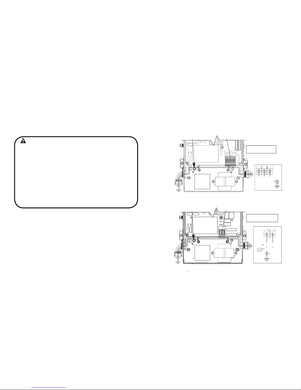
High Voltage Wiring
Line Voltage Wiring Fig. 1
WARNING
• DO NOT apply power to operator until instructed to do so.
• The Genie
®
Company recommends that line voltage wiring
be performed by a qualified electrician.
• Be sure that electrical power has been disconnected from the
input power wires being connected to the operator prior to
handling these wires. An appropriate lock-out /tag-out procedure
is recommended.
• Line voltage wiring must meet all local building codes.
• Make sure operator voltage, phase and frequency nameplate
ratings are identical to the job site line voltage ratings.
• Input power wiring must be properly sized for the operators
amperage rating located on the nameplate.
• To reduce the risk of electric shock, make sure the chassis of this
unit is properly grounded.
1) Remove LINE VOLTAGE INPUT PLUG and install proper
fittings and 1/2”conduit.
2) Route proper LINE VOLTAGE wires into operator.
3) Locate LINE INPUT terminals on circuit board. Using
correct connectors, attach wires to LINE INPUTS, and GROUND
terminal.
• Keep low
voltage and line voltage wires separate.
• Route all line voltage wires as shown. Use liquid tight fittings
and conduit.
• Plug all unused conduit holes with liquid tight plugs.
NOTE: LIQUID-TIGHT FITTINGS AND CONDUIT ARE NOT PROVIDED.
HIGH
VOLTAGE
INPUT
PLUGS
(Right
& Left)
Optional
Accessory
Modules
Optional
Additional
Transformer
LINE INPUT
TERMINALS
LINE
GROUND
208/240V 480/575V
LINE INPUT
TERMINALS
LINE
GROUND
ROUTE HIGH VOLTAGE WIRING
IN THE SHADED AREA AS SHOWN
HIGH
VOLTAGE
INPUT
PLUGS
(Right
& Left)
L1/L1
N/L2
GND
POWER CONNECTIONS
LINE IN
POWER CONNECTIONS
LINE
(HOT)
NEUTRAL
LINE 1
LINE 2
L1
L2
GND
LINE 1
LINE 2 LINE 3
L3
Three Phase
Single Phase
Optional
Additional
Transformer
115V
208V
230V
ROUTE HIGH VOLTAGE WIRING
IN THE SHADED AREA AS SHOWN
Figure 1
(SUPPLEMENT TO SECTION 5 OF THE ACCOMPANYING GCL-GH™ INSTALLATION MANUAL)
1
www.geniecompany.com 06-12
Heavy Duty Operator
GCL-GH
Page 3
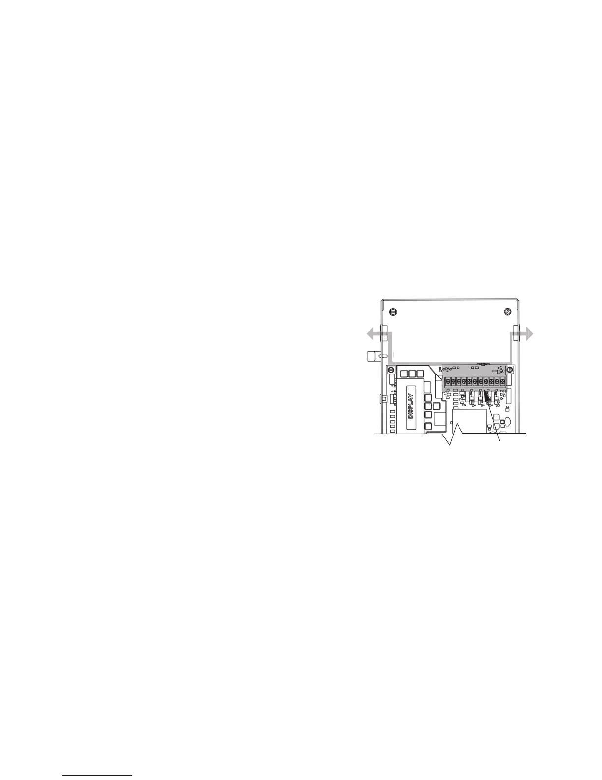
Low Voltage Wiring
1) Connect all LOW VOLTAGE control circuit wires to this side
of unit using 1/2” conduit or flexible convoluted tubing.
• Keep low voltage and line voltage wires separate.
• Route all low voltage control wiring as shown. Use liquid tight
fittings and conduit. This includes all control circuit wires such as
wall controls, timers and single button input devices as well as
radio control and safety circuit wiring. See Figs 2 through 10 in
this section.
• Plug all unused conduit holes with liquid tight plugs.
Low Voltage Control Wiring (general) Fig. 2
ROUTE LOW VOLTAGE WIRING
IN THE SHADED AREA AS SHOWN
LOW
VOLTAGE
INPUT
PLUGS
(Left &
Right)
LOW VOLTAGE
CONTROL WIRE
TERMINALS
Figure 2
NOTE: For a detailed description of control wire terminals see Appendix B in
the Standard GCL-GH
™
Installation Manual.
NOTE: LIQUID-TIGHT CONDUIT AND FITTINGS ARE NOT PROVIDED
(SUPPLEMENT TO SECTION 5 OF THE ACCOMPANYING GCL-GH™ INSTALLATION MANUAL)
2
www.geniecompany.com 06-12
Heavy Duty Operator
GCL-GH
Page 4

Right Hand /Left Hand Orientation
Shifting Release Cord SIDE A or SIDE B: Fig. 5
The release mechanism is factory installed and is designed so that
it can be right or left-hand mount. To switch the release cable:
1) Remove 4 screws, cover plate and gasket from hoist enclosure.
2) Remove 2 nuts from cable bracket, remove bracket pulling it off
end of cable.
3) Pull rubber boot inside enclosure disengaging it from cable
pass-through hole.
4) Pull cable through hole into enclosure.
4) Remove plug from cable pass-through hole on opposite side
of enclosure and plug hole where cable was before.
5) Feed cable out through new side and attach rubber boot to hole.
6) Slide cable bracket onto cable and attach to new side of enclosure
with 2 nuts.
7) Replace gasket, cover plate and 4 screws.
Shifting Manual Handwheel SIDE A to SIDE B: Fig. 4
The release mechanism is factory installed and is designed so that
it can be right or left-hand mount. To switch the handwheel:
1) Loosen the set screws (1) and remove set collar (2).
2) Slide the chain guard (3) and handwheel (4) off of hoist shaft.
3) Drive out spring pin (5) and drive it into opposite side of shaft.
3) Slide all onto opposite side in order shown and tighten set screws.
Figure 4
2
1
3
4
SIDE ASIDE B
HOLE
PLUG
COVER
PLATE
CABLE
BRACKET
Figure 5
5
3
www.geniecompany.com 06-12
Heavy Duty Operator
GCL-GH
Page 5

NEMA 4 & 4X Electric Box Parts Breakdown
1
2
3
4
5
6
7
8
Item Part Number Description Qty
1 111116.0001 BRACKET, MOUNTING, ELECTRIC BOX 2
2 111119.0001 ELEC BOX, N4 (BLACK) 1
111119.0002 ELEC BOX, N 4X (STAINLESS STEEL) 1
3 111397.0002 RECEIVER ASSY 1
4 111352.0001 ANTENNA ASSY 1
5 8706E29 SCREW, GROUND, 8-32 X 3/8" 1
6 111087.0001 XFMR, 120/208/240V, 1 PHASE 1
111087.0002 XFMR, 208/240/480V, 3 PHASE 1
111087.0003 XFMR, 575V 1
7 22634A WASHER, CUP 1
8 8706F29 SCREW, GROUND, 10-32 X 3/8" 1
YSSA DRAOB ROTALUSNI 1000.104111 9 1
10 112358.0001.S KIT, CIRCUIT BD, 1PH, CONTACT, NON-UL 1
112358.0002.S KIT, CIRCUIT BD, 1PH, RELAY, NON-UL 1
112358.0003.S KIT, CIRCUIT BD, 3PH, NNON-UL 1
112358.0004.S KIT, CIRCUIT BD, 575V, NON-UL 1
1
11 112359.0001.S COVER ASSY, N4, 1PH, GENIE, BLACK
112359.0001.S COVER ASSY, N4, 3PH, GENIE, BLACK
112359.0001.S COVER ASSY, N4, 575V, GENIE, BLACK
SS ,EINEG ,HP1 ,X4N ,YSSA REVOC S.1000.953211
SS ,EINEG ,HP3 ,X4N ,YSSA REVOC S.1000.953211
112359.0001.S COVER ASSY, N4X, 575V, GENIE, SS
1
1
NS 111405.0001 SPARE FUSE KIT
1
1
1
1
NS = NOT SHOWN
9
10
11
(SUPPLEMENT TO APPENDIX A OF THE ACCOMPANYING GCL-GH™ INSTALLATION MANUAL)
4
www.geniecompany.com 06-12
Heavy Duty Operator
GCL-GH
Page 6
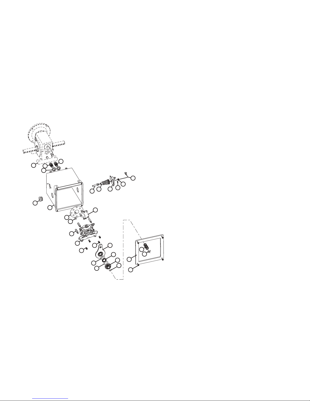
Item Part Number Description Qty
111676.0001 ENCLOSURE ASSY, BRAKE, N4
1 8094J04 SCR, #10-32 X .375 HHW S 4
2 111560.0001 GASKET, COVER, N4 1
3 111382.0002 RING, RTNG, HIGH GRIP, .40 1
4 111555.0001 SPRING, .796 OD 1
5 111600.0001 RING, CONSTANT SECTION 1
6 111539.0001 GEAR, PINION, 18T 1
7 111403.0001 WASHER, THRUST 2
8 111402.0001 BEARING, THRUST 1
9 111599.0001 RELEASE ARM ASSY, GXH 1
10 601108.0001 NUT, LK, HEX, PLD, #8-32 6
11 111346.0001 O-RING, SIZE 107 4
12 111598.0001 BRAKE ASSY, GXH 1
111707.0001 BRAKE ASSY, GHX, 3HP 1
13 111512.0001 STANDOFF, HEX, #10-32 4
14 111771.0001 SWITCH ASSY, GHX, N4 1
15 33760A04 BOLT, HH, 1/4-20 X 5/8" L 4
16 111564.0001 GASKET, GEAR REDUCER, 1HP 1
17
18 111711.0001 BUSHING, .25 ID 1
19 111572.0001
20 111563.0001 BOOT, RUBBER, GHX, N4 1
21 111562.0001 BRACKET, RELEASE CORD, N4 1
22 111557.0001 ENCLOSURE, HOIST, GXH , N4 1
23 111472.0002 BUSHING, LT, 1.00 1
24 111473.0001 LOCKNUT, NYLON, 3/8 NPT 2
25 111476.0001 CORDGRIP, LT, 3/8 NPT 1
26 111366.0001 CORDGRIP, LT, MULTI-HOLE 1
27 GEAR REDUCER
NS* 111561.0001 COVER, HOIOST ENCLOSURE, N4 1
(
NOT INCLUDED
IN 111656.0001)
*NS=NOT SHOWN
2
1
7
7
10
11
12
13
17
18
19
20
21
10
15
16
22
23
24
25
27
5
6
8
9
14
26
4
3
Brake Enclosure Assembly
5
www.geniecompany.com 06-12
Heavy Duty Operator
GCL-GH
Page 7
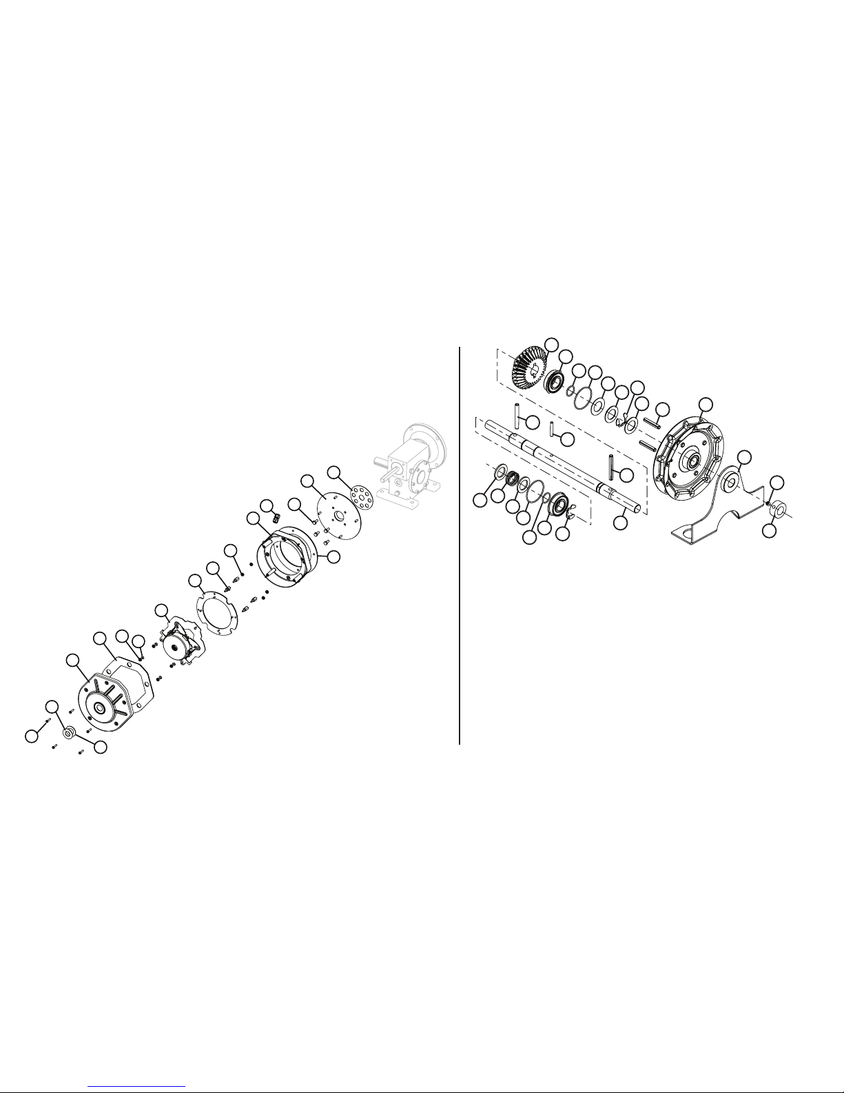
Item Part Number Description Qty
NEMA4 BRAKE ASSY
1 24501D04 SCR, SLFTPG HHW, #8 X 3/4"L 5
2 111316.0001 WASHER, .75 ID, STAINLESS STL 1
3 111478.0001 GASKET, WASHER 1
4 111139.0001 COVER, ENCLOSURE, BRAKE 1
5 111142.0001 GASKET, COVER, BRAKE, ENCLOSURE 1
6 601108.0005 NUT, LK, HEX, PLD, #8-32 4
7 111346.0001 0-RING, SIZE 107 4
8 110620.0003 BRAKE ASSY, REINFORCED, GHXT 1
9 111491.0001
ADAPTER PLATE, MOTOR/BRAKE, N4
1
10 111492.0001 STANDOFF, MOTOR/BRAKE, N4 4
11 601108.0005 NUT, LK, HEX, PLD, #8-32 4
12 111138.0001 BASE, ENCLOSURE, BRAKE 1
13 111122.0001 CORDGRIP, .065-.220 CABLE, LT 1
14 111141.0001 GASKET, BASE, BRAKE, ENCLOSURE 1
15 33760A04 BOLT, HH, 1/4-20 X 5/8"L 4
16 111541.0001
PLATE, MOUNTING, BRAKE GHXT, N4
1
17 111564.0001 GASKET, GEAR REDUCER 1
1
2
3
4
5
6
7
8
9
10
11
12
13
14
15
16
17
NEMA 4 Brake Assembly (Drawbar)
Hoist Shaft
2
1
3
4
6
5
7
6
8
9
10
11
12
Item Part Number Description Qty
111612.0001 SHAFT ASSY, HOIST, GXH, 3HP, N4
1 604297.3062 SET CLR, 5/8 ID X 1-1/8 OD 1
2 080300.1604 SCR, SET, SCH, KNRLD, 1/4-20 1
3 110411.0001 CHAIN GUARD ASSY 1
4 110872.0001 HANDWHEEL, STANDARD CHAIN 1
5 110313.0009 PIN, SPRING, .250 DIA X 1.13 2
6 110819.0003 WASHER, PLAIN, .770 ID 2
7 111382.0001 RING, RTNG, HIGH GRIP STRENGTH 2
8 086649.0030 WASHER, THRUST, .765 1
9 111709.0004 O-RING, AS568A-025 2
10 111709.0005 O-RING, AS568A-014 2
11 110695.0001 BEARING, .75 ID 2
12
111552.0001 GEAR, BEVEL, 30T, HOIST 1
13 110313.0010 PIN, SPRING, .250 DIA X 2.00 2
14 110881.0001 PIN, DOWEL, .188 X 1.13 2
15 111554.0002 SHAFT, HOIST, GXH, 3HP, N4 1
16 111937.0001 WASHER, .765 ID X 1.188 2
17 111909.0001 SPRING, .975 OD 1
13
14
13
15
7
9
16
17
16
11
10
6
www.geniecompany.com
06-12
Heavy Duty Operator
GCL-GH
Page 8

One Door Dr.
Mt. Hope, OH 44660
 Loading...