

Page 1

Operator’s Manual
Serial number range
500L Loading Shovel.......from serial n: SHOV5DL15B-1001
800L Loading Shovel.......from serial n: SHOV8DL15B-1001
800L Loading Shovel.....from serial n: SHOV8CDL15B-1001
800L Loading Shovel..... from serial n: SHOV8RDL15B-1001
Brick-Holder Basket.......from serial n: BBSKETDL15B-1001
250L Mixing Bucket..........from serial n: MXBC2515B-1001
500L Mixing Bucket...........from serial n: MXBC515B-1001
500L Man. Conc. Bucket....from s/n: CB5MADL15B-1001
500L Hyd. Conc. Bucket....from s/n: CB5HYDL15B-1001
800L Man. Conc. Bucket....from s/n: CB8MADL15B-1001
800L Hyd. Conc. Bucket....from s/n: CB8HYDL15B-1001
Original Instructions
First Edition
Second Printing
Part No. 57.0303.5251
Page 2

December 2015
First Edition - Second Printing
Contents
Introduction ..........................................Page 3
Symbol and Hazard Pict.Definition ......Page 8
General Safety.....................................Page 9
Work Area Safety.................................Page 10
Safety Precautions............................ Page 11
Legend .................................................Page 13
Attachment Description .......................Page 14
Attachment Application Field ...............Page 17
Inspections ..........................................Page 18
Operating Instructions .........................Page 22
Parking and Storage ............................Page 31
Tansport and lifting instruction.............Page 32
Maintenance ........................................Page 42
Specification ........................................Page 46
Load Charts .........................................Page 52
Diagrams And Schemes ......................Page 66
EC Declaration of Conformity ..............Page 68
TEREX Global GmbH
Bleicheplatz 2
8200 Schaffhausen
Switzerland
Technical Assistance Service
Telephone: +39 075 9418129
+39 075 9418175
e-mail: UMB.Service@terex.com
2 SHOVEL - BUCKET - BASKET Part No. 57.0303.5251
Copyright © 2015 by Terex Corporation
First Edition: Second Printing, December 2015
Genie is a registered trademark of Terex South
Dakota, Inc. in the U.S.A. and many other
countries. “GTH” is a trademark of Terex South
Dakota, Inc.
Page 3

First Edition - Second Printing December 2015
Introduction
About This Manual
Genie appreciates your choice of our machine for
your application. Our number one priority is user
safety, which is best achieved by our joint efforts.
This book is an operation and daily maintenance
manual for the user or operator of a Genie machine.
This manual should be considered a permanent part
of your machine and should remain with the machine
at all times. If you have any questions, contact Genie.
In this manual, the term "machine" can be referred
to both the attachment or the truck, according to
the context.
This manual shall be used in conjunction with the
user manual of the telehandler.
Part No. 57.0303.5251 SHOVEL - BUCKET - BASKET 3
Page 4
December 2015
Introduction
Product Identifi cation
The attachment serial number is located on the
serial label.
First Edition - Second Printing
• 500L Loading Shovel 59.0201.9019 GT
• 800L Loading Shovel 59.0201.9020 GT
• 800L Loading Shovel 59.0201.9021 GT
• 800L Loading Shovel 59.0201.9022 GT
• Brick-Holder Basket 59.0401.2032 GT
• 250L Mixing Bucket 59.0401.2018 GT
• 500L Mixing Bucket 59.0401.2016 GT
• 500L Man. Concrete Bucket 59.0401.2028 GT
• 500L Hyd. Concrete Bucket 59.0401.2029 GT
• 800L Man. Concrete Bucket 59.0401.2030 GT
• 800L Hyd. Concrete Bucket 59.0401.2031 GT
4 SHOVEL - BUCKET - BASKET Part No. 57.0303.5251
Intended Use
The Loading Shovels and Mixing Bucket are designed
to move and to mix loose materials. Brick-Holder
Basket is designed to lift and lower loose materials.
Use of this product in any other way is prohibited
and contrary to its intended use.
Page 5

First Edition - Second Printing December 2015
Introduction
Bulletin Distribution and
Compliance
Safety of product users is of paramount importance
to Genie. Various bulletins are used by Genie
to communicate important safety and product
information to dealers and machine owners.
The information contained in the bulletins is tied to
specific machines using the machine model and
serial number.
Distribution of bulletins is based on the most current
owner on record along with their associated dealer,
so it is important to register your machine and keep
your contact information up to date.
To ensure safety of personnel and the reliable
continued operation of your machine, be sure to
comply with the action indicated in a respective
bulletin.
Contacting the Manufacturer
At times it may be necessary to contact Genie.
When you do, be ready to supply the model number
and serial number of your machine, along with your
name and contact information. At minimum, Genie
should be contacted for:
• Accident reporting
• Questions regarding product applications and
safety
• Standards and regulatory compliance information
• Current owner updates, such as changes in
machine ownership or changes in your contact
information. See Transfer of Ownership, below.
Transfer of Machine Ownership
Taking a few minutes to update owner information
will ensure that you receive important safety,
maintenance and operating information that applies
to your machine.
Please register your machine by visiting us on the
web at www.genielift.co.uk.
Part No. 57.0303.5251 SHOVEL - BUCKET - BASKET 5
Page 6

December 2015
Introduction
First Edition - Second Printing
Danger
Failure to obey the instructions and safety rules in
this manual will result in death or serious injury.
Do Not Operate Unless:
You learn and practice the principles of safe
attachment operation contained in this operator’s
manual.
1. Avoid hazardous situations.
Know and understand the safety rules
before going on to the next section.
2. Always perform a pre-operation inspection.
3. Always perform function tests prior to use.
4. Only use the machine as it was intended.
You read, understand and obey the manufacturer’s
instructions and the safety rules, the safety and
operator’s manuals, and the decals applied on
the machine.
You read, understand and obey the employer’s
safety rules and work-site regulations.
You read, understand and obey all applicable
governmental regulations.
You are properly trained to safely operate the
machine.
6 SHOVEL - BUCKET - BASKET Part No. 57.0303.5251
Page 7

First Edition - Second Printing December 2015
Introduction
Hazard Classifi cation
Safety alert symbol: used to
alert you to potential personal
injury hazards. Obey all safety
messages that follow this
symbol to avoid possible injury
or death
DANGER
WARNING
CAUTION
NOTICE
Indicates a hazardous situation
which, if not avoided, will result
in death or serious injury.
Indicates a hazardous situation
which, if not avoided, could result
in death or serious injury.
Indicates a hazardous situation
which, if not avoided, could result
in minor or moderate injury.
Indicates a property damage
message.
Standards
The following standards and/or regulations apply to
this machine:
Directive
2006/42/EC Machinery Directive
Safety Sign Maintenance
Replace any missing or damaged safety signs.
Keep operator safety in mind at all times. Use mild
soap and water to clean safety signs. Do not use
solvent-based cleaners because they may damage
the safety sign material.
Part No. 57.0303.5251 SHOVEL - BUCKET - BASKET 7
Page 8

December 2015
First Edition - Second Printing
Symbol and Hazard Pictorials Defi nitions
Falling object
Hazard
No ride Brick
Holder
Basket
Close the gate Falling Hazard
Read the
operator's
manual
Crush Hazard
Fix brick holder with
Chain to Forks plate
Keep clear of
moving parts
8 SHOVEL - BUCKET - BASKET Part No. 57.0303.5251
Page 9

First Edition - Second Printing December 2015
140 mm
General Safety
09.4618.1355
09.4618.1355
09.4618.1354 09.4618.1352
09.4618.1354
800 Kg
09.4618.1353
09.4618.1353
09.4618.1352
09.4618.0922
09.4618.0922
Part No. 57.0303.5251 SHOVEL - BUCKET - BASKET 9
Page 10

December 2015
Work Area Safety
For work area safety, refer to the same section in
the telehandler operator's manual.
First Edition - Second Printing
10 SHOVEL - BUCKET - BASKET Part No. 57.0303.5251
Page 11

First Edition - Second Printing December 2015
Safety Precautions
Requirements for Machine
Operators
Operators who use the machine regularly or
occasionally (i.e. for transport reasons) shall have
the following prerequisites:
health:
before and during any operation, operators shall
never take alcoholic beverages, medicines or other
substances that may alter their psycho-physical
conditions and, consequently, their working abilities.
physical:
good eyesight, acute hearing, good co-ordination and
ability to carry out all required operations in a safe
way, according to the instructions of this manual.
mental:
ability to understand and apply the enforced rules,
regulations and safety precautions. They shall be
careful and sensible for their own as well as for the
others’ safety and shall desire to carry out the work
correctly and in a responsible way.
emotional:
they shall keep calm and always be able to evaluate
their own physical and mental conditions.
training:
they shall read and be familiar with this handbook,
its enclosed graphs and diagrams, the identification
and hazard warning plates. They shall be skilled and
trained about the machine use.
Requirements for Service
Personnel
Personnel in charge of the machine maintenance
shall be qualified, specialised in the maintenance
of telehandlers, and shall have the following
prerequisites:
physical:
good eyesight, acute hearing, good co-ordination
and ability to carry out all required maintenance
operations in a safe way, according to this manual.
mental:
ability to understand and apply the enforced rules,
regulations and safety precautions. They shall be
careful and sensible for their own as well as for the
others’ safety and shall desire to carry out the work
correctly and in a responsible way.
training:
they shall read and be familiar with this handbook,
its enclosed graphs and diagrams, the identification
and warning plates. They shall be skilled and trained
about the machine functioning.
From a technical point of view, routine maintenance
of the machine is not a complex procedure and can
be carried out by the machine operator too, provided
he has a basic knowledge of mechanics.
The operator shall have a licence (or a driving
licence) when provided for by the laws enforced in
the country where the machine
ask the competent bodies. In Italy the operator must
be at least 18 year old.
Part No. 57.0303.5251 SHOVEL - BUCKET - BASKET 11
is operated. Please,
Page 12

December 2015
Safety Precautions
First Edition - Second Printing
Working clothes
During work, but especially when maintaining or
repairing the machine, operators must wear suitable
protective clothing:
• Overalls or any other comfortable garments.
Operators should not wear clothes with large
sleeves or objects that can get stuck in moving
parts of the machine.
• Protective helmet.
• Protective gloves.
• Working shoes.
Personal protective equipment
Under special working conditions, the following
personal protective equipment should be used:
• Breathing set (or dust mask).
• Ear-protectors or equivalent equipment.
• Goggles or facial masks.
Use only approved safety workwear in good
condition.
12 SHOVEL - BUCKET - BASKET Part No. 57.0303.5251
Page 13

First Edition - Second Printing December 2015
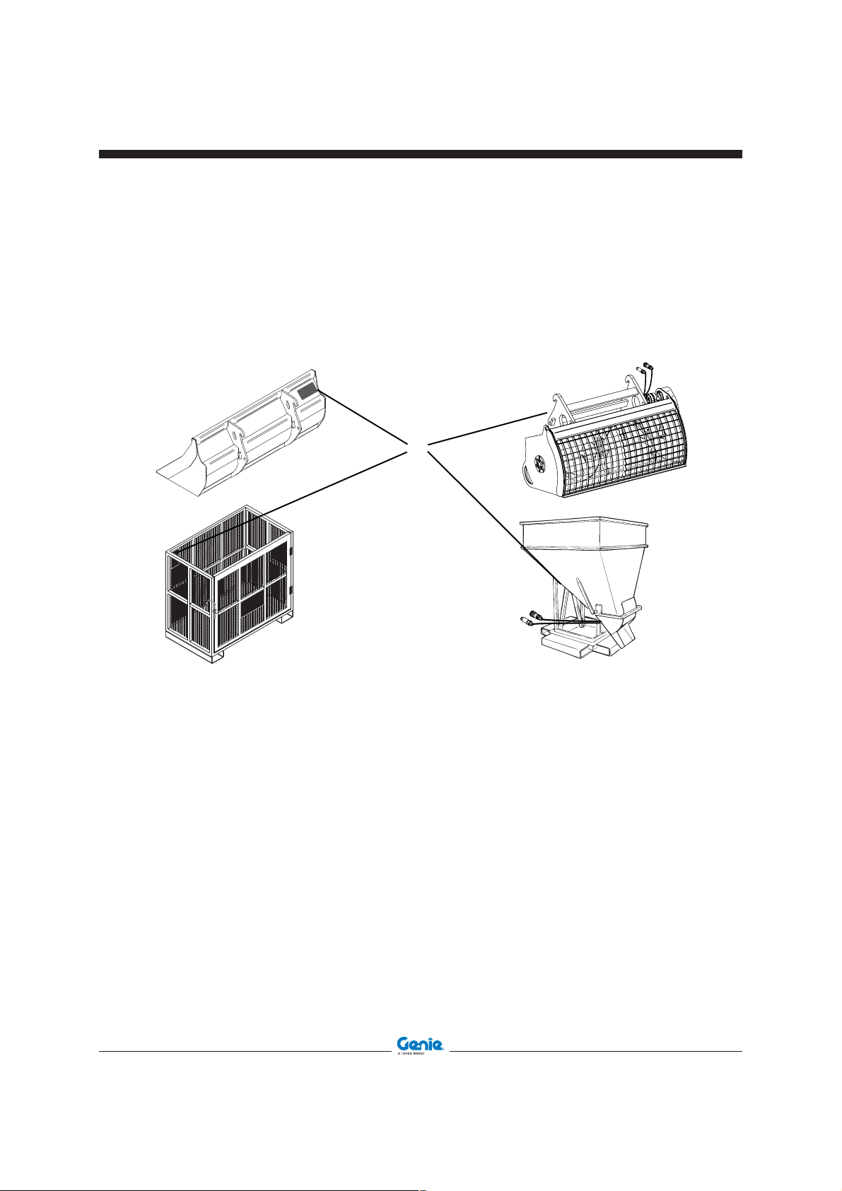
Legend
Shovel, Bucket, Brick-Holder Basket main components
A. Fork Slots
B. Coupling Frame
C. Quick coupling (if any)
Part No. 57.0303.5251 SHOVEL - BUCKET - BASKET 13
Page 14
December 2015
Attachment Description
First Edition - Second Printing
Shovel
The shovel consists of a welded concave shaped
steel structure designed to move and load loose
material such as soil, sand debris, inert material.
The main components of this structure are the front
blade, which works as the leading edge of the shovel
“cutting” the material volume and separating the part
which is gathered by the shovel itself, the central
concave shell, which provides the volume for the
material to be gathered, and the side walls, which
laterally close the useful volume of the shovel.
On the rear area of the shovel, there are two
shaped plates welded to its main structure and
designed to be coupled with the GTH telehandlers
standard attachment interface. Considering the
typical limitation in the maximum rotation of the
attachment articulation, the design of the shovel
and its mechanical interface with the attachments
articulation is optimized to provide the best
compromise in terms of material loading and
unloading capabilities.
Brick Holder Basket
This attachment is designed to handle bricks pallets,
and other materials and to place them where are
necessary in the construction working sites.
It consists of a main basket made by welded steel
square shaped tubes and steel grids preventing any
debris exceeding small sizes that can accidentally
drop from the basket when this is operated at height.
A door is hinged on the right side of the basket
to make it easier to load and unload the pallets/
materials on/from the basket.
The door can be secured in the closed position by
a dedicated latch. The overall basket is installed
on a bottom structure having two rectangular
hollow shaped steel tubes working as slots for the
telehandlers forks.
The longitudinal movement of the basket, when
engaged with the forks, is controlled by a chain and
a shackle which must be secured before using the
basket to handle materials.
This equipment is coupled to the telehandler
through the coupling frame B
14 SHOVEL - BUCKET - BASKET Part No. 57.0303.5251
This equipment is coupled to the telehandler
through the forks slots A
Page 15

First Edition - Second Printing December 2015
Attachment Description
Mixing Bucket
This bucket is designed to produce limited volumes
of concrete by mixing its main components (cement,
aggregates, sand and water) and to discharge such
volumes (when the concrete is ready). It mainly
consists of a welded concave shaped steel structure
designed to gather from ground aggregates, cement
and sand, before the concrete mixing phase is
started, and then to mix these components with water
in order to produce concrete. The main components
of this welded structure are the front blade, which
works as the leading edge of the bucket “cutting”
the material volume and separating the part which
is gathered by the bucket itself, the central concave
shell, which provides the volume for the material to
be gathered and mixed, and the side walls, which
laterally close the useful volume of the bucket. To
mix the concrete components, a mixing blade made
by welded and shaped plates, is provided and
installed longitudinally to the main axis of the bucket.
This blade rotates on bearings installed on the side
walls of the bucket and is powered by a hydraulic
motor and a gear box which are located externally
of the right side wall of the bucket.
The concrete, after the mixing phase, can be
discharged through a dedicated door located on
the bottom of the bucket and activated through
a mechanism and a hydraulic cylinder. The
mixing blade and the concrete discharge door
are hydraulically powered through the hydraulic
auxiliary line available on the top of the boom. These
two functions are controlled by a dedicated radio
remote control device which can be operated also
by operators working outside of the machine cabin.
Before the concrete mixing phase is started, the top
of the bucket must be closed by a dedicated door,
made by a steel grid and hinged on the top of the
rear wall of the bucket, with the aim of protection
against moving parts. The steel grid allows the
operator to check when the concrete is ready for
discharge. On the rear area of the bucket, there are
two shaped plates welded to its main structure and
designed to be coupled with the GTH telehandlers
standard attachments interface.
This equipment is coupled to the telehandler
through the coupling frame B
Part No. 57.0303.5251 SHOVEL - BUCKET - BASKET 15
Page 16

December 2015
Attachment Description
Concrete Bucket
The bucket mainly consists of a welded pyramid
shaped steel structure designed to handle limited
volumes of concrete from one place to another place
inside the typical construction working sites and to
discharge such volumes of concrete.
This pyramidal structure is open on the top to allow
the concrete to be easily loaded and has a section
regularly reducing towards the bottom to facilitate
the discharge of the concrete.
This discharge operation is allowed by a dedicated
steel door, located on the bottom of the bucket which
can be activated by a mechanical lever manually
moved by the operator or, according to the models
selected, by a mechanical articulation which is
hydraulically operated through the hydraulic auxiliary
line available on the top of the boom.
The overall bucket and door mechanism is installed
on a bottom structure having four rectangular
hollow shaped steel tubes working as slots for the
telehandlers forks.
The longitudinal movement of the bucket, when
engaged with the forks, is controlled by a chain and
a shackle which must be secured before using the
bucket to handle materials.
First Edition - Second Printing
This equipment is coupled to the telehandler
through the forks slots A
16 SHOVEL - BUCKET - BASKET Part No. 57.0303.5251
Page 17

First Edition - Second Printing December 2015
Attachment Application Field
The following table represents the application field of attachment installed on Genie telehandlers
GTH-2506 GTH-4014 GTH-4018 GTH-4016R GTH-4018R GTH-5021R
500 L Loading
Shovel
800 L Loading
Shovel
Brick-Holder
Basket
250 L Mixing
Bucket
500 L Mixing
Bucket
500 L Manual
Concrete
Bucket
500 L
Hydraulic
Concrete
Bucket
800 L Manual
Concrete
Bucket
800 L
Hydraulic
Concrete
Bucket
Part No. 57.0303.5251 SHOVEL - BUCKET - BASKET 17
Page 18

December 2015
Inspections
Do Not Operate Unless:
You learn and practice the principles of safe
machine operation contained in this operator’s
manual and in the telehandler one.
1. Avoid hazardous situations.
2. Always perform a pre-operation inspection.
Know and understand the pre-operation
inspection before going on to the next
section.
3. Always perform function tests prior to use.
4. Only use the machine as it was intended.
First Edition - Second Printing
Pre-operation Inspection
Fundamentals
It is the responsibility of the operator to perform a
pre-operation inspection and routine maintenance.
The pre-operation inspection is a visual inspection
performed by the operator prior to each work shift.
The inspection is designed to discover if anything
is apparently wrong with a telehandler and/or with
an equipment before the operator performs the
function tests.
The pre-operation inspection also serves to
determine if routine maintenance procedures are
required. Only routine maintenance items specified
in this manual may be performed by the operator.
If damage or any unauthorized variation from
factory delivered condition is discovered, the
telehandler and/or the equipment must be tagged
and removed from service.
Repairs to the telehandler and/or the equipment
may only be made by a qualified service
technician, according to the manufacturer's
specifications. After repairs are completed, the
operator must perform a pre-operation inspection
again before going on to the function tests.
Scheduled maintenance inspections shall be
performed by qualified service technicians,
according to the manufacturer's specifications.
18 SHOVEL - BUCKET - BASKET Part No. 57.0303.5251
Page 19

First Edition - Second Printing December 2015
Inspections
Pre-operation Inspection
Make sure the operator's manuals are intact,
legible and placed inside the telehandler.
Be sure that all decals are legible and in
place.
Check for Hydraulic oil leaks.
Checking the following components or areas for
damage, improperly installed or missing parts and
unauthorized modifications:
Hydraulic hoses and fittings
Nuts, bolts and other fastners
Check the entire structure for:
Cracks on welds or structural components
Dents or damage to the structure
Excessive rust, corrosion or oxidation
Part No. 57.0303.5251 SHOVEL - BUCKET - BASKET 19
Page 20

December 2015
Inspections
Do Not Operate Unless:
You learn and practice the principles of safe
machine operation contained in this operator’s
manual and in the telehandler one.
1. Avoid hazardous situations.
2. Always perform a pre-operation inspection.
First Edition - Second Printing
Function Test Fundamentals
The function tests are designed to discover any
malfunctions before the machine is put into service.
The operator must follow the step-by-step instructions
to test all machine functions.
A malfunctioning machine must never be used. If
malfunctions are discovered, the machine must
be tagged and removed from service. Repairs
to the machine may only be made by a qualified
service technician, according to the manufacturer’s
specifications.
After repairs are completed, the operator must perform
a pre-operation inspection and function tests again
before putting the machine into service.
3. Always perform function tests prior to use.
Know and understand the function tests
before going on to the next section.
4. Only use the machine as it was intended.
20 SHOVEL - BUCKET - BASKET Part No. 57.0303.5251
Page 21

First Edition - Second Printing December 2015
Inspections
Function Tests
Before getting started, refer to telehandler operator's
manual.
Test the Control Lever
(at every use)
• Using the control lever, momentarily lock and
unlock the attachment for those telehandlers
with hydraulic cylinder
Result: All the functions should operate
smoothly.
Test the correct open and close
movements of the concrete discharge
door (manually or hydraulically
powered).
(at every use)
• Using the function enable switch button A
move the functions joystick toward right or
left to open or close the door of the Concrete
Bucket.
• By the mechanical lever momentarily open
and close the door of the Concrete Bucket
Result: All the functions should operate
smoothly.
Test the Hydraulic movements for
Mixing bucket
(at every use)
• Using the dedicated switches on the control
panel, check the movement of the mixing
blade and the movement of the door.
Result: All the functions should operate
smoothly.
Test the lock system of the Brick-Holder
Basket gate.
(at every use)
• Move pin A upwards and open the basket
gate. Close the basket gate and move pin A
downwards through the hole.
Result: All the functions should operate
smoothly.
Part No. 57.0303.5251 SHOVEL - BUCKET - BASKET 21
Page 22

December 2015
Operating Instruction
First Edition - Second Printing
Fundamentals
The Operating Instructions section provides instructions for each aspects of machine operation.
It is the operator's responsability to follow all the
safety rules and instructions in the operator's safety and responsibilities manuals.
Do Not Operate Unless:
You learn and practice the principles of safe
machine operation contained in this operator’s
manual and in the telehandler one.
1. Avoid hazardous situations.
2. Always perform a pre-operation inspection.
3. Always perform function tests prior to use.
4. Only use the machine as it was
intended.
Only trained and authorized personnel should be
permitted to operate a machine. If more than one
operator is expected to use a machine at different times in the same work shift, they must all be
qualified operators and are all expected to follow
all safety rules and instructions in the operator's,
safety and responsibilities manuals.
That means every new operator should perform
a pre-operation inspection, function test, and a
workplace inspection before using the machine.
Additionally, everyone working on or near the product also needs to be familiar with the applicable
safety precautions.
22 SHOVEL - BUCKET - BASKET Part No. 57.0303.5251
Page 23

First Edition - Second Printing December 2015
Operating Instruction
Quick Attach Instructions
Version with mechanical locking
1 Drive to the place where you will release the
mounted attachment (when possible, a solid
and sheltered site).
2 Disconnect the quick connectors of the attachment
(if any).
3 Pull out the mechanical pin locking the attachment
after removing the safety split-pin at its end.
4 Rest the attachment flat on the ground.
5 Pitch the attachment holding frame forward and
lower the boom to release the attachment upper
lock.
6 Move back with the machine and drive to the new
attachment to be coupled.
7 Hold the frame pitched forward and hook the
upper lock of the new attachment.
8 Retract and raise the attachment a small distance.
It will center automatically on the quick coupling
frame.
9 Refit mechanical locking pin fixing it with its safety
split-pin.
10 Re-couple the connectors of the attachment (if
any).
Version with hydraulic locking (optional)
1. Drive to the place where you will release the
mounted attachment (when possible, a solid
and sheltered site).
2. Disconnect the quick connectors of the attachment
(if any).
3. Rest the attachment flat on the ground.
4. Press the Lock/Unlock Enabling Switch and keep
it pressed up to the end of Step 5.
5. Free the attachment moving the functions
joystick.
6. Pitch the attachment holding frame forward and
lower the boom to release the attachment upper
lock.
7. Move back with the machine and drive to the new
attachment to be coupled.
8. Hold the frame pitched forward and hook the
upper lock of the new attachment.
9. Retract and raise the attachment a small
distance. It will center automatically on the quick
coupling frame.
10. Coupling the attachment moving the functions
joystick with the Lock/Unlock Enabling Switch.
11. Re-couple the connectors of the attachment (if
any).
Part No. 57.0303.5251 SHOVEL - BUCKET - BASKET 23
Page 24

December 2015
Operating Instructions
First Edition - Second Printing
Operation
Loading Shovel
500L Loading Shovel 59.0201.9019 GT
800L Loading Shovel 59.0201.9020 GT
800L Loading Shovel 59.0201.9021 GT
800L Loading Shovel 59.0201.9022 GT
• Couple the Shovel and hold it in position by means
of the attachment locking system (mechanical or
hydraulic)
• Engage materials slowly
• To remove the attachment, remove the
attachment locking system (mechanical or
hydraulic) then carefully tilt the attachment
forward, lower the boom resting the attachment
on the ground and retract the boom.
Mixing Bucket
250L Mixing Bucket 59.0401.2018 GT
500L Mixing Bucket 59.0401.2016 GT
• Couple the Mixing Bucket and hold it in
position by means of the attachment locking
system (mechanical or hydraulic)
• Connect the Hydraulic hoselines
• To remove the attachment, remove the
attachment locking system (mechanical or
hydraulic) then carefully tilt the attachment
forward, lower the boom resting the attachment
on the ground, disconnect the Hydraulic
hoselines, and retract the boom.
Once the attachment quick connectors have
been disconnected from the boom connectors,
take care to reconnect them to the proper rest
connectors that are present on the Mixing
Bucket, in order to prevent impurities from
entering the circuit. Carefully protect the rest
connectors with the provided plugs when they
are not used.
.
Brick-Holder Basket
Brick-Holder Basket 59.0401.2032 GT
• Couple the Brick-Holder Basket by the forks
slots.
• Using the chain and shackle, secure the
attachment to the Forks carriage.
• To remove the attachment rest the attachment
on the ground, remove the chain and shackle,
then reract the boom.
Concrete Bucket
500L Man. Concrete Bucket 59.0401.2028 GT
500L Hyd. Concrete Bucket 59.0401.2029 GT
800L Man. Concrete Bucket 59.0401.2030 GT
800L Hyd. Concrete Bucket 59.0401.2031 GT
• Couple the Concrete Bucket by the forks slots.
• Using the chain and shackle, secure the
attachment to the Fork carriage.
• Connect the Hydraulic hoselines.
• To remove the attachment, rest the
attachment on the ground, disconnect the
Hydraulic hoselines, remove the chain and
shackle, then retract the boom.
Load Limiting System control
panel
Refer to telehandler operator's manual.
Using The Load Chart
Refer to telehandler operator's manual
24 SHOVEL - BUCKET - BASKET Part No. 57.0303.5251
Page 25

First Edition - Second Printing December 2015
Operating Instructions
Controller Movements - Functions
Joystick - Shovel
GTH-2506, GTH-4014 and GTH-4018
Refer to telehandler operator's manual
Before discharging the material, make sure that
nobody is within its working range.
Press and hold the function enable switch B and
move the joystick to the left to tilt the bucket up.
Press and hold the function enable switch B and
move the joystick to the right to tilt the bucket down.
Controller Movements - Functions
Joystick - Shovel
GTH-4016R, GTH-4018R and GTH-5021R
Refer to telehandler operator's manual
Before discharging the material, make sure that
nobody is within its working range.
WITH RIGHT JOYSTICK (Standard
Confi guration) and with LEFT JOYSTICK
(Optional Confi guration)
Functions joystick with enable
switch (B)
Part No. 57.0303.5251 SHOVEL - BUCKET - BASKET 25
Functions joystick with enable switch
(B)
Page 26

December 2015
Operating Instructions
Controller Movements - Mixing
Bucket
For all the telehandler models
First Edition - Second Printing
Proceed as follow:
Set the Hydraulic Mixing Bucket Oil Direction
Switch A to position 0 and press the Mixing Bucket
Switch B to enable the movement of the internal
mixer of the bucket. Switch B has a block which
can be locked for continuous operation. Before
switching to another position, ensure the block is
unlocked at the top of switch B.
Setting switch A to position 2 or 1, regulates the
oil flow direction, to rotate the mixing blade either
clockwise or counterclowise.
To open the bucket door, set switch A to position
0 and press the Auxiliary Hydraulic Circuit Switch
. Then set switch A to position 1 or 2 to open or
C
close the bucket door.
To discharge the concrete, set switch A to position
0, set switch C to position 0, set switch A to
position 1 or 2, the mixer start to rotate clockwise
or counterclowise, pushing out the concrete.
Phase Switch Position
A 0 Stop Oil Flow
MIXING B 1 Enable Mix.
Bucket Circuit
A 1 or 2 Rotate the Mix
OPEN
DOOR
DISCHARGE C 0 Enable Mix. Blade
A 0 Stop Oil Flow
C 1 Enable Mix.
Bucket Door
A 1 or 2 Open/Close
Bucket Door
A 0 Stop Oil Flow
movements
A 1 or 2 Rotate Mix Blade
For the use of this equipment and its remote
control, please read the specific manual
26 SHOVEL - BUCKET - BASKET Part No. 57.0303.5251
Page 27

First Edition - Second Printing December 2015
Operating Instructions
Controller movements - Functions
Joystick - Hydraulic Concrete
Bucket
GTH-2506, GTH-4014, and GTH-4018
Before discharging the concrete, make sure that
nobody is within its working range.
Press and keep switch A and B and move the Function
Joystick toward left to close the Bucket door or to the
right to open the Bucket door.
Functions joystick with enable switch
(B) and with white thumb switch (A)
Controller movements - Single
Functions Joystick - Hydraulic
Concrete Bucket
GTH-4016R, GTH-4018R, GTH-5021R
Controller movements - Dual
Functions Joystick - Hydraulic
Concrete Bucket
GTH-4016R, GTH-4018R, GTH-5021R
Functions joystick with enable switch
(B) and with white thumb switch (A)
Press and keep switch A and B on the Left
Control Joystick and move it toward ahead to
open the Bucket door or behind to close the
Bucket door.
Before discharging the concrete, make sure
that nobody is within its working range.
Press and keep switch A and B and move the Function
Joystick toward left to close the Bucket door or to
the right to open the Bucket door.
Functions joystick with enable switch
(B) and with white thumb switch (A)
Part No. 57.0303.5251 SHOVEL - BUCKET - BASKET 27
Page 28

December 2015
Operating Instructions
First Edition - Second Printing
Loading Equipment
Loading the Shovel
• When using a shovel, load the material only
when the boom is completely retracted and push
against the heap with straight wheels.
• Approach the load to be handled perpendicularly
and check that the machine is level on the
inclinometer.
• Insert the shovel under the load and raise it some
centimetres.
• Pitch the load back to cradle the load.
• Engage materials slowly.
When loading round-shaped objects (as petrol
drums, etc) bind them with straps or ropes and
travel at reduced speed.
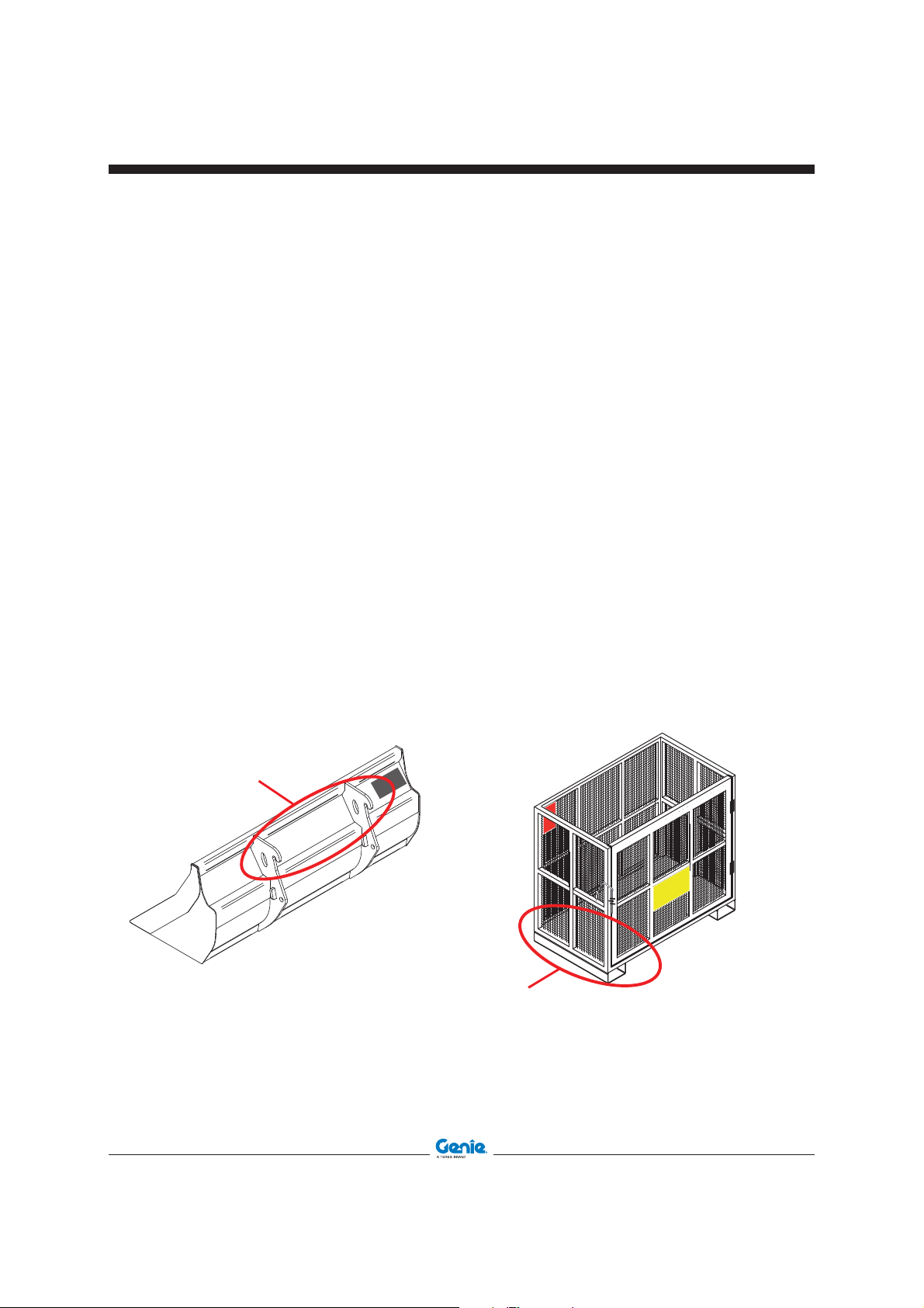
Loading the Brick-Holder Basket.
• Approach the place where
the material is stocked;
• lower the brick-holder
basket on the ground;
• open the gate;
• insert the material;
• close the gate and secure
it through the dedicated
pin 1.
09.4618.1355
Unsecured objects may fall out. Always ensure that the material is completely enclosed by
the basket and at the gate is secured prior to
lifting/lowering.
The brick-holder basket is designed to handle
bricks pallets and other materials. IT IS NOT
A MAN-PLATFORM. Don’t use for elevating or
transporting people!
Do not use for digging operations.
Don’t use the shovel for rising or transporting
people
09.4618.1352
28 SHOVEL - BUCKET - BASKET Part No. 57.0303.5251
Page 29

First Edition - Second Printing December 2015
Operating Instructions
Loading the Concrete Bucket
• Approach the place where the material is
stocked;
• lower the concrete bucket on the ground;
• ensure that the discharge door is closed; if not,
move lever 2 clockwise for the manual version
or the functions joystick for the hydraulic one;
• introduce the concrete through the top end.
Loading the Mixing Bucket
For the use of this equipment please read the
specific manual.
Part No. 57.0303.5251 SHOVEL - BUCKET - BASKET 29
Page 30

December 2015
Operating Instructions
Trasporting the Loaded Material
First Edition - Second Printing
Once the material is loaded, operate as follow:
• identify any risks present on the route to be
travelled;
• raise the equipment to the transport height of
300-500mm from the ground;
• ensure that the load/attachment is high enough
to clear all objects before starting to move;
• avoid excessive rough terrain when travelling;
• consider that when transporting load permissible
gradients are 10% downhill, 15% uphill, 5% side;
• initiate movements of the load with the lowest
available speed;
• do not allow workers/bystanders to walk or work
under the load;
• do not leave the load unattended
• ensure that all personnel are out of the travel/
lifting hazard zones before operating;
;
• When driving on a rise with loaded material,
proceed in forward gear and travel with load in
the lowest possible position.
• When sloping downward with loaded material,
proceed into reverse.
• When driving on a rise with empty shovel, proceed into reverse.
• When sloping downward with empty shovel,
proceed in forward gear.
Load Landing
Before a load is lifted, a place should be prepared
where it is to be put down. The nature of the load will
determine the type of preparation necessary.
30 SHOVEL - BUCKET - BASKET Part No. 57.0303.5251
Page 31

First Edition - Second Printing December 2015
Parking and Storage
Short inactivity and attachment
storage
To release the attachment from the telehandler:
• Approach the place where you will release the
equipment
• Lower the equipment on the ground.
• Stop the engine of the telehandler
• Disconnect the hydraulic pipes of the equipment
from the boom fittings.
• Restart the engine.
• Operate the joystick to release the equipment
from the quick coupling plate.
• Tilt the coupling plate forward and lower the
boom to release the upper look of the equipment.
• Move back with the telehandler.
Part No. 57.0303.5251 SHOVEL - BUCKET - BASKET 31
Page 32

December 2015
Transport and Lifting Instructions
First Edition - Second Printing
Moving the Equipment
When the equipment shall be moved, use only
means having a suitable capacity. The characteristic
data are detailed in the relevant chapter of this
manual and on the identification plate.
Shovels and Mixing Bukets shall be moved using
forks.
• Shovel 500L 59.0201.9019GT
10.5in/
268mm
21.2in/
541mm
38.5in/980mm
14.3in/
365mm
• Shovel 800L 59.0201.9020GT
11.3in/
289mm
31.8in/
810mm
32 SHOVEL - BUCKET - BASKET Part No. 57.0303.5251
11.9in/
303mm
25.9in/
658mm
46.25in/1175mm
10in/
254mm
17.28in/
439mm
37.1in/
943mm
Page 33

First Edition - Second Printing December 2015
Transport and Lifting Instructions
• Shovel 800L 59.0201.9021GT
37.0in/
8.77in/
223mm
11.4in/
292mm
940mm
23.8in/
607mm
42.1in/1070mm
15.8in/
403mm
• Shovel 800L 59.0201.9022GT
12.8in/
327mm
22.4in/
570mm
46.10in/
1170mm
25.8in/
656mm
44.88in/ 1140mm
16.6in/
422mm
Part No. 57.0303.5251 SHOVEL - BUCKET - BASKET 33
Page 34

December 2015
Transport and Lifting Instructions
• Mixing Bucket 250L 59.0401.2018GT
12.4in/
315mm
First Edition - Second Printing
5.6in/
143mm
14.2in/
363mm
CoG of Mixing
Bucket
structure
33.0in/
840mm
13.0in/
331mm
7.5in/
192mm
59.4in/
1510mm
34.2in/
870mm
32.0in/
815mm
32.0in/
815mm
CoG of Mixing Bucket full of concrete
CoG of Mixing Bucket structure
13.5in/
344mm
CoG of Mixing Bucket
full of concrete
1.02in/
26mm
CoG of Mixing Bucket structure
13.5in/
345mm
17.3in/
441mm
31.2in/
795mm
36.2in/
920mm
2.4in/
62mm
35.0in/
890mm
34 SHOVEL - BUCKET - BASKET Part No. 57.0303.5251
Page 35

First Edition - Second Printing December 2015
Transport and Lifting Instructions
• Mixing Bucket 500L 59.0401.2016GT
69.1in/
1630mm
CoG of Mixing Bucket structure
28.4in/
723mm
CoG of Mixing Bucket full of concrete
34.4in/
876mm
38.8in/
986mm
35.7in/
909mm
5in/
127mm
12.5in/
320mm
18.7in/
17.9mm
3.5in/
90mm
14.6in/
373mm
18.7in/
7.9mm
42.7in/
1086mm
17.1in/
436mm
18.7in/
477mm
14.4in/
367mm
CoG of Mixing
Bucket structure
CoG of Mixing
Bucket structure
Part No. 57.0303.5251 SHOVEL - BUCKET - BASKET 35
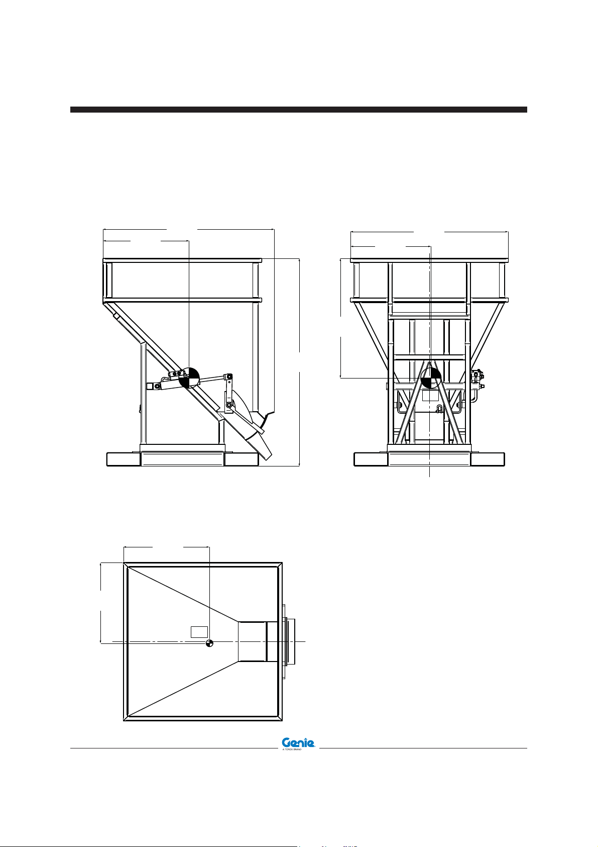
Page 36

December 2015
Transport and Lifting Instructions
First Edition - Second Printing
• Brick-Holder Basket 59.0401.2032GT
Insert the forks into the dedicated lugs 1
• Concrete Bucket 500L
59.0401.2028GT
59.0401.2029GT
• Concrete Bucket 800L
59.0401.2030GT
59.0401.2031GT
Insert the forks into the dedicated lugs 1
36 SHOVEL - BUCKET - BASKET Part No. 57.0303.5251
Page 37

First Edition - Second Printing December 2015
Transport and Lifting Instructions
• Brick-Holder Basket
59.0401.2032GT
23.8in/
605mm
15.8in/
402mm
23.2in/
590mm
28.9in/
736mm
47.6in/
1210mm
41.1in/
1046mm
45.2in/
1150mm
23.2in/
590mm
32.4in/
825mm
CoG of Busket full of bricks
Part No. 57.0303.5251 SHOVEL - BUCKET - BASKET 37
Page 38

December 2015
Transport and Lifting Instructions
• Concrete Bucket 500 Manual Discharge
59.0401.2028GT
First Edition - Second Printing
24.7in/
629mm
24.76in/
629mm
49.21in/
1250mm
51.9in/
1320mm
26.49in/
673mm
23.14in/
588mm
45.27in/
1150mm
23.14in/
588mm
38 SHOVEL - BUCKET - BASKET Part No. 57.0303.5251
Page 39

First Edition - Second Printing December 2015
Transport and Lifting Instructions
• Concrete Bucket 500 L Hydraulic Discharge
59.0401.2029GT
24.7in/
628mm
24.7in/
628mm
49.2in/
1250mm
51.9in/
1320mm
26.4in/
673mm
23.3in/
593mm
45.2in/
1150mm
23.3in/
593mm
Part No. 57.0303.5251 SHOVEL - BUCKET - BASKET 39
Page 40

December 2015
Transport and Lifting Instructions
• Concrete Bucket 800L Manual Discharge
59.0401.2030G
First Edition - Second Printing
24.7in/
629mm
49.21in/
1250mm
59.8in/
1520mm
34.3in/
873mm
23.1in/
588mm
45.2in/
1150mm
24.7in/
629mm
23.1in/
588mm
40 SHOVEL - BUCKET - BASKET Part No. 57.0303.5251
Page 41
First Edition - Second Printing December 2015
Transport and Lifting Instructions
• Concrete Bucket 800L Hydraulic Discharge
59.0401.2031GT
24.7in/
629mm
49.21in/
1250mm
59.8in/
1520mm
34.3in/
873mm
23.1in/
589mm
45.2in/
1150mm
24.7in/
629mm
23.1in/
589mm
Part No. 57.0303.5251 SHOVEL - BUCKET - BASKET 41
Page 42

December 2015
Maintenance
Observe and Obey:
Only routine maintenance items specified in this
manual shall be performed by the operator.
First Edition - Second Printing
Maintenance Symbols Legend
The following symbols have been used in this
manual to help communicate the intent of the
instructions. When one or more of the symbols
appear at the beginning of a maintenance
procedure, it conveys the meaning below.
Indicates that tools will be required to
perform this procedure.
Scheduled maintenance inspections shall be
completed by qualified service technicians,
according to the manufacturer’s specifications
and the requirements specified in the
responsibilities manual.
Indicates that new parts will be
required to perform this procedure.
Indicates that a cold engine will be
required to perform this procedure.
42 SHOVEL - BUCKET - BASKET Part No. 57.0303.5251
Page 43

First Edition - Second Printing December 2015
Maintenance
Scheduled Maintenance
Machines that have been out of service for more
than three months must receive the quarterly
inspection before they are put back into service.
Model
Serial number
Date
Hour meter
Machine owner
Inspected by (print)
Inspector signature
Inspector title
Inspector company
Instructions
· Make copies of this report to use for each inspection.
· Select the appropriate checklist(s) for the type of inspection
to be performed.
Daily or 8 hours
Inspection: A
Checklist A Y N R
A-1 Manuals and decals
A-2 Pre-operation inspect
A-3 Function tests
A-4 Checking the Chains
· Place a check in the appropriate box after each inspection
procedure is completed.
· Use the step-by-step procedures in this section to learn how
to perform these inspections.
· If any inspection receives an “N”, tag and remove the machine
from service, repair and re-inspect it. After repair, place a
check in the “R” box.
Part No. 57.0303.5251 SHOVEL - BUCKET - BASKET 43
Page 44

December 2015
Maintenance
A-1
Inspect the Manuals and Decals
First Edition - Second Printing
Genie specifications require that this procedure be
performed every 8 hours or daily, whichever comes
first.
Maintaining the operator’s and safety manuals in
good condition is essential to safe machine operation.
Manuals are included with each machine and should
be stored in the container provided in the operator's
compartment. An illegible or missing manual will not
provide safety and operational information necessary
for a safe operating condition.
In addition, maintaining all of the safety and
instructional decals in good condition is mandatory for
safe machine operation. Decals alert operators and
personnel to the many possible hazards associated
with using this machine. They also provide users
with operation and maintenance information. An
illegible decal will fail to alert personnel of a procedure
or hazard and could result in unsafe operating
conditions.
1 Check to make sure that the operator's and safety
manuals are present and complete in the storage
container in the operator's compartment.
3 Open the operator's manual to the decals
inspection section. Carefully and thoroughly
inspect all decals on the machine for legibility
and damage.
Result: The machine is equipped with all required
decals, and all decals are legible and in good
condition.
Result: The machine is not equipped with all
required decals, or one or more decals are
illegible or in poor condition. Remove the
machine from service until the decals are
replaced.
4 Always return the manuals to the storage
container after use.
Note: Contact your authorized Genie distributor or
Genie Industries if replacement manuals or decals
are needed.
2 Examine the pages of each manual to be sure
that they are legible and in good condition.
Result: The operator's manual is appropriate for
the machine and all manuals are legible and in
good condition.
Result: The operator's manual is not appropriate
for the machine or all manuals are not in good
condition or is illegible. Remove the machine
from service until the manual is replaced.
44 SHOVEL - BUCKET - BASKET Part No. 57.0303.5251
Page 45

First Edition - Second Printing December 2015
Maintenance
A-2
Perform Pre-operation Inspection
Genie specifications require that this procedure be
performed every 8 hours or daily, whichever comes
first.
Completing a Pre-operation Inspection is essential to
safe machine operation. The Pre-operation Inspection
is a visual inspection performed by the operator
prior to each work shift. The inspection is designed
to discover if anything is apparently wrong with a
machine before the operator performs the function
tests. The Pre-operation Inspection also serves to
determine if routine maintenance procedures are
required.
A-3
Perform Function Tests
Genie specifications require that this procedure be
performed every 8 hours or daily, whichever comes
first.
Completing the function tests is essential to safe
machine operation. Function tests are designed to
discover any malfunctions before the machine is put
into service. A malfunctioning machine must never
be used. If malfunctions are discovered, the machine
must be tagged and removed from service.
A-4
Check the Chains
Check the Chains and shackles used to fix the
Concrete Buckets and Brick-Holder Basket to the
fork carriage.
Part No. 57.0303.5251 SHOVEL - BUCKET - BASKET 45
Page 46
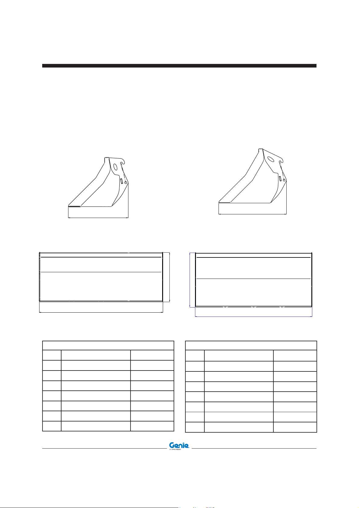
December 2015
Specifi cation
First Edition - Second Printing
Loading Shovel 500L
part number 59.0201.9019GT
for GTH-2506
Loading Shovel 800L
part number 59.0201.9020GT
for GTH-2506
TECHNICAL DATA
46 SHOVEL - BUCKET - BASKET Part No. 57.0303.5251
Width 2024
Height 810 mm
Length 980 mm
Weight 355 Kg
Payload 500 L
CoG Width 1012 mm
CoG Height 268 mm
CoG Length 541 mm
Width 2024 mm
Height 940 mm
Length 1175 mm
Weight 420 kg
Payload 800 L
Cog Width 1012 mm
CoG Height 303 mm
CoG Length 658 mm
TECHNICAL DATA
Page 47

First Edition - Second Printing December 2015
Specifi cation
Loading Shovel 800L
part number 59.0201.9021GT
for GTH-4014,GTH-4018, GTH-5021R
Loading Shovel 800L
part number 59.0201.9022GT
for GTH-4016R, GTH-4018R
TECHNICAL DATA
Part No. 57.0303.5251 SHOVEL - BUCKET - BASKET 47
Width 2435
Height 940 mm
Length 1070 mm
Weight 450 Kg
Payload 800 L
CoG Width 1217.5 mm
CoG Height 292 mm
CoG Length 607 mm
Width 2435 mm
Height 1170 mm
Length 1140 mm
Weight 510 Kg
Payload 800 L
CoG Width 1217.5 mm
CoG Height 327 mm
CoG Length 656 mm
TECHNICAL DATA
Page 48

December 2015
Specifi cation
First Edition - Second Printing
Mixing Bucket 250L
part number 59.0401.2018GT
for GTH-2506
Mixing Bucket 500L
part number 59.0401.2016GT
for GTH-4014, GTH-4018
TECHNICAL DATA
48 SHOVEL - BUCKET - BASKET Part No. 57.0303.5251
Width 1510 mm
Height 840 mm
Length 795 mm
Weight 460 Kg
Payload 250 L
CoG Width 953 mm
CoG Height 344 mm
CoG Length 363 mm
Width 1650 mm
Height 990 mm
Length 880 mm
Weight 550 Kg
Payload 500 L
CoG Width 723 mm
CoG Height 456 mm
CoG Length 373 mm
TECHNICAL DATA
Page 49

First Edition - Second Printing December 2015
Specifi cation
Brick-Holder Basket
part number 59.0401.2032GT
for all the range.
TECHNICAL DATA
Width 1210 mm
Height 1150 mm
Length 825 mm
Weight 120 Kg
Payload 500 L
CoG Width 605 mm
CoG Height 590 mm
CoG Length 402 mm
Part No. 57.0303.5251 SHOVEL - BUCKET - BASKET 49
Page 50

December 2015
Specifi cation
First Edition - Second Printing
500L Manual Concrete Bucket
part number 59.0401.2028GT
for all the range
500L Hydraulic Concrete Bucket
part number 59.0401.2029GT
for all the range
TECHNICAL DATA
50 SHOVEL - BUCKET - BASKET Part No. 57.0303.5251
Width 1110 mm
Height 1320 mm
Lenght 1110 mm
Weight 230 Kg
Payload 500 L
CoG Width
CoG Height 673 mm
CoG Length 629 mm
588 mm
Width 1110 mm
Height 1320 mm
Lenght 110 mm
Weight 244 Kg
Payload 500 L
CoG Width
CoG Height 673 mm
CoG Length 628 mm
TECHNICAL DATA
593 mm
Page 51

First Edition - Second Printing December 2015
Specifi cation
800L Manual Concrete Bucket
part number 59.0401.2030GT
for GTH-4014, GTH-4018, GTH-4016R, GTH4018R
800L Hydraulic Concrete Bucket
part number 59.0401.2031GT
for GTH-4014, GTH-4018, GTH-4016R, GTH4018R
TECHNICAL DATA
Part No. 57.0303.5251 SHOVEL - BUCKET - BASKET 51
Width 1110 mm
Height 1520 mm
Lenght 1110 mm
Weight 250 Kg
Payload 800 L
CoG Width 588 mm
CoG Height 873 mm
CoG Length 629 mm
Width 1110 mm
Height 1520 mm
Lenght 1110 mm
Weight 264 Kg
Payload 800 L
CoG Width 589 mm
CoG Height 873 mm
CoG Length 629 mm
TECHNICAL DATA
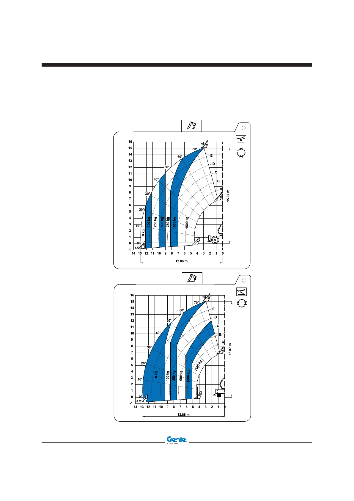
Page 52

December 2015
Load Charts
First Edition - Second Printing
GTH-2506, Loading Shovel and Mixing Bucket 250L
GTH-2506
09.4618.1426
52 SHOVEL - BUCKET - BASKET Part No. 57.0303.5251
Page 53

First Edition - Second Printing December 2015
Load Charts
GTH-4014
09.4618.1752
GTH-4014, Loading Shovel and Mixing Bucket 500L
GTH-4014
09.4618.1751
Part No. 57.0303.5251 SHOVEL - BUCKET - BASKET 53
Page 54

December 2015
GTH-4018
09.4618.1724
Load Charts
GTH 4018, Loading Shovel and Mixing Bucket 500L
First Edition - Second Printing
GTH-4018
09.4618.1725
54 SHOVEL - BUCKET - BASKET Part No. 57.0303.5251
Page 55
First Edition - Second Printing December 2015
Load Charts
GTH-4016R, Loading Shovel and Mixing Bucket
GTH-4016 R
0°
180°
GTH-4016 R
09.4618.1942
±90°ĈĈĈ
09.4618.1941
Part No. 57.0303.5251 SHOVEL - BUCKET - BASKET 55
Page 56

December 2015
Load Charts
GTH-4016R, Loading Shovel and Mixing Bucket
GTH-4016 R
First Edition - Second Printing
0°
180°
GTH-4016 R
09.4618.1940
±90°ĈĈĈ
09.4618.1939
56 SHOVEL - BUCKET - BASKET Part No. 57.0303.5251
Page 57

First Edition - Second Printing December 2015
Load Charts
GTH-4018R, Loading Shovel and Mixing Bucket
GTH-4018 R
0°
180°
GTH-4018 R
±90°ĈĈĈ
GTH-4018 R
09.4618.1854
09.4618.1852
±90°ĈĈĈ
180°
0°
09.4618.1853
Part No. 57.0303.5251 SHOVEL - BUCKET - BASKET 57
Page 58

December 2015
Load Charts
GTH-5021R, Loading Shovel and Mixing Bucket
GTH-5021 R
First Edition - Second Printing
GTH-5021 R
180°
0°
GTH-5021 R
09.4618.1708
±90°ĈĈĈ
09.4618.1709
09.4618.1710
58 SHOVEL - BUCKET - BASKET Part No. 57.0303.5251
Page 59

First Edition - Second Printing December 2015
Load Charts
GTH-2506, Brick-Holder Basket and Concrete Bucket
GTH-2506
09.4618.1637
Part No. 57.0303.5251 SHOVEL - BUCKET - BASKET 59
Page 60

December 2015
Load Charts
GTH-4014
09.4618.1639
First Edition - Second Printing
GTH-4014, Brick-Holder Basket and Concrete Bucket
GTH-4014
09.4618.1641
60 SHOVEL - BUCKET - BASKET Part No. 57.0303.5251
Page 61
First Edition - Second Printing December 2015
GTH-4018
09.4618.1715
Load Charts
GTH-4018, Brick-Holder Basket and Concrete Bucket
GTH-4018
09.4618.1714
Part No. 57.0303.5251 SHOVEL - BUCKET - BASKET 61
Page 62

December 2015
Load Charts
First Edition - Second Printing
GTH-4016R, Brick-Holder Basket and Concrete Bucket
GTH-4016 R
0°
180°
09.4618.1925
GTH-4016 R
16
15
14
13
12
11
10
9
8
7
6
20°
5
4
10°
3
2
1
0°
0
-1
-3.7°
-2
50°
40°
30°
0 kg
250 kg
60°
500 kg
13.35 m
70°
1000 kg
75°
E
D
C
B
A
0.6 m
g
k
0
0
0
2
±90°ĈĈĈ
15.31 m
0123456789101112131415
09.4618.1926
62 SHOVEL - BUCKET - BASKET Part No. 57.0303.5251
Page 63

First Edition - Second Printing December 2015
Load Charts
GTH-4016R, Brick-Holder Basket and Concrete Bucket
GTH-4016 R
16
15
14
13
12
11
10
9
8
7
6
20°
5
4
10°
3
2
1
0°
0
-1
-3.7°
-2
50°
40°
30°
1000 kg
1500 kg
700 kg
60°
2500 kg
2000 kg
13.35 m
70°
75°
E
D
C
B
A
0.6 m
g
k
0
0
0
4
3000 kg
0123456789101112131415
09.4618.1923
15.42 m
180°
0°
GTH-4016 R
16
15
14
13
12
11
10
9
8
7
6
20°
5
4
10°
3
2
1
0°
0
-1
-3.7°
-2
30°
450 kg
50°
40°
750 kg
1000 kg
60°
1500 kg
13.35 m
70°
75°
E
D
kg
C
0
0
5
2
300
2000 kg
B
kg
0
A
0.6 m
g
k
0
0
0
4
±90°ĈĈĈ
15.42 m
0123456789101112131415
09.4618.1924
Part No. 57.0303.5251 SHOVEL - BUCKET - BASKET 63
Page 64

December 2015
Load Charts
First Edition - Second Printing
GTH-4018R, Brick-Holder Basket and Concrete Bucket
GTH-4018 R
0°
180°
GTH-4018 R
±90°ĈĈĈ
GTH-4018 R
09.4618.1849
09.4618.1850
180°
±90°ĈĈĈ
0°
09.4618.1851
64 SHOVEL - BUCKET - BASKET Part No. 57.0303.5251
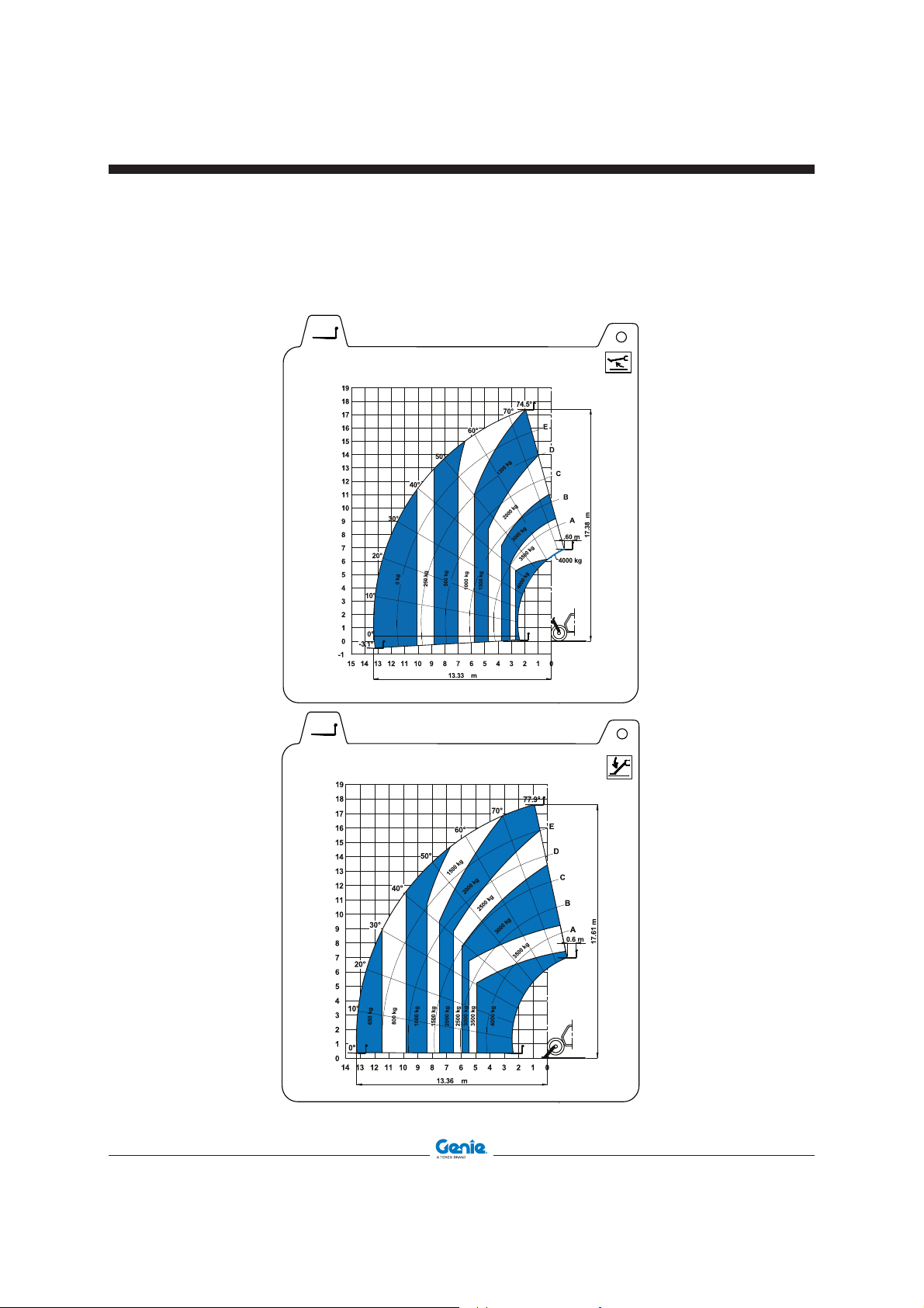
Page 65

First Edition - Second Printing December 2015
Load Charts
GTH-5021 R
0°
180°
A
B
C
D
E
70°
60°
50°
40°
30°
20°
0°
77.50°
10°
-3.50°
012345678910111213141516
171819
0
-1
1
2
3
4
5
6
7
8
9
10
11
12
13
14
15
-2
16
17
18
19
20
21
22
18.24 m
20.64 m
4000 kg
3000 kg
2000 kg
1500 kg
1000 kg
750 kg
500 kg
0 kg
250 kg
0.60 m
09.4618.1642
GTH-5021 R
A
B
40°
30°
20°
0°
10°
-3.50°
012345678910111213141516
171819
0
-1
1
2
3
4
5
6
7
8
9
10
11
12
13
14
-2
18.24 m
20.64 m
2500 kg
1500 kg
1000 kg
500 kg
0 kg
250 kg
0.60 m
C
D
E
70°
60°
50°
77.50°
15
16
17
18
19
20
21
22
±90°ĈĈĈ
09.4618.1644
GTH 5021R, Brick-Holder Basket and Concrete Bucket
GTH-5021 R
22
21
20
19
18
17
16
15
14
13
12
11
10
9
8
7
6
5
4
3
2
1
0
-1
-2
40°
30°
20°
750 kg
10°
475 kg
0°
-3.50°
171819
1000 kg
60°
50°
2500 kg
1500 kg
2000 kg
18.24 m
3000 kg
77.50°
70°
E
D
C
B
A
0.60 m
5000 kg
4000 kg
012345678910111213141516
20.86 m
09.4618.1643
±90°ĈĈĈ
180°
0°
Part No. 57.0303.5251 SHOVEL - BUCKET - BASKET 65
Page 66

December 2015
Diagrams and Schemes
Hydraulic Diagram
only for Hydraulic Concrete Bucket
First Edition - Second Printing
66 SHOVEL - BUCKET - BASKET Part No. 57.0303.5251
Page 67

First Edition - Second Printing December 2015
Diagrams and Schemes
Hydraulic Diagram
Only for Mixing Bucket
Part No. 57.0303.5251 SHOVEL - BUCKET - BASKET 67
Page 68

December 2015
First Edition - Second Printing
Content of the EC Declaration of Conformity
TEREX Global GmbH hereby declares that the machinery described below complies with the provisions
of the following Directives:
1. EC Directive 2006/42/EC, Machinery Directive.
The machinery described below is suitable for Genie telehandlers, models specified in the user manual.
Model/Type:
Description:
Serial Number:
Manufacture Date:
Country of Manufacture:
Manufacturer:
TEREX Global GmbH
Bleicheplatz 2
8200 Schaffhausen
Switzerland
European representative:
Genie UK LTD
The Maltings
Wharf Road, Grantham, Lincolnshire
NG31 6BH United Kingdom
Empowered signatory:
Place of issue:
Date of issue:
68 SHOVEL - BUCKET - BASKET Part No. 57.0303.5251
Page 69

www.genielift.com
:yB detubirtsiD
 Loading...