

Page 1

Service and Repair Manual
Serial Number Range
GS™-2669 DC
from GS69F-18000
101
This manual includes:
Repair procedures
Fault Codes
Electrical and
Hydraulic Schematics
GS™-3369 DC
GS™-4069 DC
For detailed maintenance
procedures, refer to the
appropriate Maintenance
Manual for your machine.
Original Instructions
Part No. 1306585GT
Rev A1
August 2022
from GS69M-
Page 2

Service and Repair Manual August 2022
Introduction
Introductio n Introductio n
Important Inf or matio n
Important
Read, understand and obey the safety rules
and operating instructions in the appropriate
Operator's Manual on your machine before
attempting any procedure.
This manual provides troubleshooting and
repair procedures for qualified service
professionals.
Basic mechanical, hydraulic and electrical
skills are required to perform most procedures.
However, several procedures require
specialized skills, tools, lifting equipment and a
suitable workshop. In these instances, we
strongly recommend that maintenance and
repair be performed at an authorized Genie
dealer service center.
Compliance
Technical Publications
Genie has endeavored to deliver the highest
degree of accuracy possible. However,
continuous improvement of our products is a
Genie policy. Therefore, product specifications
are subject to change without notice.
Readers are encouraged to notify Genie of
errors and send in suggestions for
improvement. All communications will be
carefully considered for future printings of this
and all other manuals.
Contact Us:
Internet: www.genielift.com
E-mail: awp.techpub@terex.com
Find a Manual for this Model
Go to http://www.genielift.com
Machine Classification
Group A/Type 3 as defined by ISO 16368
Machine Design Life
Unrestricted with proper operation, inspection
and scheduled maintenance.
Use the links to locate Service Manuals,
Maintenance Manuals, Service and Repair
Manuals, Parts Manuals and Operator's
Manuals.
Copyright © 2020 by Terex Corporation
1306585GT Rev A, May 2021
Second Edition, First Printing
Genie is a registered trademark of Terex South Dakota,
Inc. in the U.S.A. and many other countries.
“GS” is a trademark of Terex South Dakota, Inc.
ii GS
™
-2669 DC • GS™-3369 DC • GS™-4069 DC Part No. 1306585GT
Page 3

August 2022 Service and Repair Manual
Section – Schematics, Legends and schematics
Introduction
Revision History
Revision History
Revision Date Section Procedure / Page / Description
A 5/2021
A1 8/2022 Fault Codes Update fault codes
Initial Release
Reference Examples:
Section – Repair Procedure, 4-2
Section – Fault Codes, All charts
Electronic Version
Click on any content or proc edure in the Table of Contents to view
the update.
Part No. 1306585GT GS
™
-2669 DC • GS™-3369 DC • GS™-4069 DC iii
Page 4

Service and Repair Manual August 2022
Introduction
Serial Number Legend
1 Model
2 Facility code
3 Sequence number
4 Serial label, ((located inside cover))
5 Serial number, ((stamped on chassis))
iv GS
™
-2669 DC • GS™-3369 DC • GS™-4069 DC Part No. 1306585GT
Page 5

August 2022 Service and Repair Manual
Safety Rules
Section 1 Safety Rules
General Saf ety Rul es
Danger
Failure to obey the instructions and safety rules in
this manual and the appropriate Operator's Manual
on your machine will result in death or serious
injury.
Many of the hazards identified in the operator's
manual are also safety hazards when
maintenance and repair procedures are
performed.
Do not modify or alter a MEWP without prior
written permission from the manufacturer.
Do Not Perform Maintenance
Unless:
You are trained and qualified to perform
maintenance on this machine.
You read, understand and obey:
• manufacturer's instructions and safety rules
• employer's safety rules and worksite
regulations
• applicable governmental regulations
You have the appropriate tools, lifting
equipment and a suitable workshop.
Part No. 1306585GT GS
™
-2669 DC • GS™-3369 DC • GS™-4069 DC v
Page 6

Service and Repair Manual August 2022
Read each procedure thoroughly. This
manual and the decals on the machine,
use signal words to identify the following:
Safety alert symbol
alert pers
personal injury hazards. Obey all
safety messages that follow this
symbol to avoid possible injury or
death.
Indicates a imminently hazardous
situation which, if not avoided,
will result in death or serious
injury.
Indicates a potentially hazardous
situation which, if not avoided,
could result in death or serious
injury.
Indicates a potentially hazardous
situation which, if not avoided,
may cause minor or moderate
injury.
Indicates a potentially hazardous
situation which,
may result in property damage.
Be sure to wear protective eye wear and
other protective clothing if the situation
warrants it.
Be aware of potential crushing hazards
such as moving parts, free swinging or
unsecured
placing loads. Always wear approved
steel
Be sure to keep sparks, flames and
lighted tobacco away from flammable and
combustible materials like battery gases
and engine fuels. Always have an
approved fire extinguisher within easy
reach.
Be sure that all tools and workin
are properly maintained and ready for
use. Keep work surfaces clean and free
of debris that could get into machine
components and cause damage.
Be sure any forklift, overhead crane or
other lifting or supporting device is fully
capable of suppor
weight to be lifted. Use only chains or
straps that are in good condition and of
ample capacity.
Be sure that fasteners intended for one
time use (i.e., cotter pins and self
nuts) are not reused. These components
may fai
Be sure to properly dispose of old oil or
other fluids. Use an approved container.
Please be environmentally safe.
Be sure that your workshop or work area
is properly ventilated and well lit.
Safety Rules
Personal Safety
Any person working on or around a machine must
be aware of all known safety hazards. Personal
safety and the continued safe operation of the
machine should be your top priority.
—used to
onnel to potential
Workplace Safety
Any person working on or around a machine must
be aware of all known safety hazards. Personal
safety and the continued safe operation of the
machine should be your top priority.
ting and stabilizing the
g areas
components when lifting or
-toed shoes.
vi GS
-locking
l if they are used a second time.
if not avoided,
™
-2669 DC • GS™-3369 DC • GS™-4069 DC Part No. 1306585GT
Page 7

August 2022
Table of Contents
Introduction Introduction ...................................................................................................... ii
Important Information ......................................................................................... ii
Find a Manual for this Model ............................................................................... ii
Revision History ................................................................................................ iii
Serial Number Legend ....................................................................................... iv
Section 1 Safety Rules ...................................................................................................... v
General Safety Rules ......................................................................................... v
Section 2 Specifications ................................................................................................... 1
Machine Specifications ....................................................................................... 1
Performance Specifications ................................................................................ 1
Hydraulic Oil Specifications ................................................................................ 2
Hydraulic Component Specifications ................................................................... 5
Manifold Component Specifications .................................................................... 5
Machine Component Weights ............................................................................. 6
Battery Specifications ......................................................................................... 6
Hydraulic Hose and Fitting Torque Specifications ............................................... 7
Torque Procedure .............................................................................................. 8
Part No. 1306585GT GS
™
-2669 DC • GS™-3369 DC • GS™-4069 DC vii
Page 8

August 2022
Table of Contents
Section 3 Repair Procedures ......................................................................................... 10
Introduction ...................................................................................................... 10
Platform Controls ........................................................................................... 12
1-1 Circuit Board .............................................................................................. 13
1-2 Joystick ...................................................................................................... 14
1-3 Platfrom Controls Alarm ............................................................................. 14
1-4 Platfrom Emergency Stop Button................................................................ 15
Platform Components .................................................................................... 16
2-1 Platform ..................................................................................................... 16
2-2 Platform Extension Deck ............................................................................ 17
Scissor Components ..................................................................................... 19
3-1 Scissor Assembly, GS-2669 DC ................................................................. 20
3-2 Scissor Assembly, GS-3369 DC ................................................................. 23
3-3 Scissor Assembly, GS-4069 DC ................................................................. 27
3-4 Wear Pads ................................................................................................. 30
3-5 Lift Cylinders .............................................................................................. 32
3-6 Height Angle Sensor .................................................................................. 33
How to Replace the Height Angle Sensor .................................................... 33
Ground Controls ............................................................................................ 35
4-1 Software Revision Level ............................................................................. 36
4-2 Machine Setup ........................................................................................... 37
4-3 Auxiliary Platform Lowering ........................................................................ 38
4-4 Level Sensor - Models without Outriggers .................................................. 38
4-5 Level Sensor - Models with Outriggers ....................................................... 41
4-6 Service Override Mode............................................................................... 43
viii GS
™
-2669 DC • GS™-3369 DC • GS™-4069 DC Part No. 1306585GT
Page 9

August 2022
Table of Contents
Hydraulic Pump .............................................................................................. 45
5-1 Hydraulic Pump .......................................................................................... 45
How to Test the Hydraulic Pump .................................................................. 45
How to Remove the Hydraulic Pump............................................................ 45
How to Calibrate the Hydraulic Pump........................................................... 46
Manifolds ........................................................................................................ 48
6-1 Function Manifold Components .................................................................. 48
6-2 Valve Adjustments - Function Manifold ....................................................... 50
How to Check the System Proportional Relief Valve .................................... 50
How to Adjust the Oscillate Relief Valve ...................................................... 51
How to Adjust the Steer Relief Valve............................................................ 52
How to Adjust the Platform Up Relief Valve ................................................. 53
6-3 Outrigger Manifold Components ................................................................. 58
6-4 Valve Coils ................................................................................................. 59
Hydraulic Tank................................................................................................ 61
7-1 Hydraulic Tank ........................................................................................... 61
Steer Axle Components ................................................................................. 62
8-1 Yoke Assembly........................................................................................... 62
8-2 Steer Cylinder ............................................................................................ 64
8-3 Tie Rod ...................................................................................................... 64
8-4 Oscillate Cylinder ....................................................................................... 65
8-5 Oscillate Hoses .......................................................................................... 65
8-6 Steer Angle Sensor .................................................................................... 67
Part No. 1306585GT GS
™
-2669 DC • GS™-3369 DC • GS™-4069 DC ix
Page 10

August 2022
Table of Contents
Non-steer Axle Components ......................................................................... 72
9-1 Drive Motors .............................................................................................. 72
9-2 Drive Hub ................................................................................................... 74
Outrigger Components .................................................................................. 75
10-1 Outrigger Cylinder .................................................................................... 75
10-2 Outrigger Calibration ................................................................................ 76
Platform Overload Components .................................................................... 78
How to Calibrate the Platform Overload System .......................................... 78
11-2 Platform Overload Recovery..................................................................... 80
11-3 Down Limit Height .................................................................................... 82
How to Calibrate the Down Limit Height ...................................................... 82
x GS
™
-2669 DC • GS™-3369 DC • GS™-4069 DC Part No. 1306585GT
Page 11

August 2022
Table of Contents
Section 4 Fault Codes ..................................................................................................... 83
Introduction ...................................................................................................... 83
GCON I/O Map ................................................................................................. 86
Platform Overload Fault Codes...................................................................... 88
Operation Indicator Codes (OIC) ...................................................................... 93
Diagnostic Trouble Codes (DTC) ...................................................................... 93
Troubleshooting "HXXX" and "PXXX" Faults ..................................................... 94
Fault Inspection Procedure ............................................................................... 95
Type "HXXX" Faults ......................................................................................... 97
Type "PXXX" Faults ........................................................................................ 100
Type "UXXX" Faults ....................................................................................... 102
Type "FXXX" Faults ........................................................................................ 104
Type "CXXX" Faults ....................................................................................... 107
Part No. 1306585GT GS
™
-2669 DC • GS™-3369 DC • GS™-4069 DC xi
Page 12

August 2022
Table of Contents
Section 5 Schematics ................................................................................................... 109
Introduction .................................................................................................... 109
Electrical Schematic Abbreviations and Wire Color Legends .......................... 110
Hydraulic Component Legend ........................................................................ 113
Electrical Symbols Legend ............................................................................. 114
Hydraulic Symbols Legend ............................................................................. 115
Limit Switch Legend ....................................................................................... 116
Fuse, Ground and Platform Control Boxes ................................................. 117
Fuse Box Layout, All Models .......................................................................... 118
Ground Control Box Layout ............................................................................ 119
Platform Control Box Layout ........................................................................... 121
Electrical Schematics .................................................................................. 123
Electrical Schematic ....................................................................................... 124
Hydraulic Schematics .................................................................................. 127
Hydraulic Schematic ...................................................................................... 128
xii GS
™
-2669 DC • GS™-3369 DC • GS™-4069 DC Part No. 1306585GT
Page 13

August 2022 Service and Repair Manual
Fluid capacities
Hydraulic tank
(maximum fill capacity)
allons
iters
Hydraulic system (including tank)
allons
iters
Drive hub
EP 9
gear oil API service classification GL5
unces
c
Tires and wheels
Wheel lugs
9 @ 5/8-18
Lug nut torque, dry
Rear
lbs
230 Nm
Lug nut torque, lubricated
Rear
lbs
176 Nm
Lug nut torque, dry
Front
lbs
122 Nm
Lug nut torque, lubricated
Front
lbs
92 Nm
Castle nut (steer end)
Castle nut torque
lbs
47.5 Nm
Tire size
12D380
Tire ply rating
8
Tire diameter
n
66 cm
Tire width
n
m
Weight, each
bs
g
Drive speed, maximum
Platform stowed
Forward direction
ph
m/h
ec
12.2 m / 6.1 sec
Platform stowed
Reverse direction
ph
m/h
ec
ec
Platform raised
ph
m/h
ec
ec
Braking distance, maximum
High range on paved
surface
t
m
Gradeability
See Operator's Manual
Function speed, maximum from platform controls
(with maximum rated load in platform)
Platform up
Platform down
econds
econds
GS-3369 DC
Platform up
Platform down
econds
econds
GS-4069 DC
Platform up
Platform down
econds
23 to 33 seconds
Outrigger leveling, maximum
Front
Back
Side to side
5.3°
4.2°
11.7°
Specifications
Section 2 Specificatio ns
Machine Specifi c atio ns
Machine Specifications
18 g
0 or SAE 90 multipurpose hypoid
Performance S peci f icati o ns
Performance Specifications
16.5 g
62.5 l
68.1 l
24.5 o
725 c
12.2 m / 9.1 s
170 ft-
130 ft-
90 ft-
68 ft-
GS-2669 DC
35 ft-
29 to 39 s
26 to 36 s
4.5 m
7.2 k
40 ft / 6.1 s
3.0 m
4.8 k
40 ft / 9.1 s
0.3 m
0.5 k
40 ft / 91 s
12.2 m / 91 s
3 f
0.9
Non-marking, foam filled, RT
26 x
For operational specifications, refer to the
Operator's Manual.
26 i
12 i
30 c
177.5 l
80.5 k
34 to 44 s
24 to 34 s
56 to 66 s
Part No. 1306585GT GS
™
-2669 DC • GS™-3369 DC • GS™-4069 DC 1
Page 14

Service and Repair Manual August 2022
Hydraulic Fluid Specifications
Genie specifications require hydraulic oils which are
designed to give maximum protection to hydraulic
systems, have the ability to perform over a wide
temperature range, and the viscosity index should
exceed 140. They should provide
oxidation prevention, corrosion inhibition, seal
conditioning, and foam and aeration suppression
properties.
Cleanliness level,
minimum
ISO 15/13
Water content,
maximum
pm
Recommended Hydraulic Fluid
Hydraulic oil type
Chevron Rando HD Premium
ISO Grade
32
Viscosity index,
maximum
200
Optional Hydraulic Fluids
Mineral based
Shell Tellus S2 V 32
Shell Tellus S2 V 46
Shell Tellus S4 VX 32
Shell Donax TG (Dexron III)
Chevron 5606A
Biodegradable
46
Fire resistant
5046
Optional fluids may not have
the same hydraulic lifespan and
may result in component
damage.
Do not top off with incompatible
hydraulic fluids. Hydraulic fluids
may be incompatible due to the
differences in base additive
chemistry. When incompatible
fluids are mixed, insoluble
materials may form and deposit
in the hydraulic system,
plugging hydraulic lines, filters,
control valves and may result in
component damage.
Specifications
Hydraulic Oi l Spec ific ations
Hydraulic Oil Specifications
excellent antiwear,
250 p
Petro Canada Environ MV
UCON Hydrolube HP-
Note: Genie specifications require additional
equipment and special installation instructions for
the approved optional fluids. Consult Genie
Product Support before use.
Note: Do not operate the machine when the
ambient air temperature is consistently above
120°F / 49°C.
Hydraulic Fluid Temperature
Range
Ambient air temperature
1 Chevron hydraulic oil 5606A
2 Petro-Canada Environ MV 46
3 UCON Hydrolube HP-5046D
4 Chevron Rando HD premium oil MV
Note: Extended machine operation can cause the
hydraulic fluid temperature to increase beyond its
maximum allowable range. If the hydraulic fluid
temperature consistently exceeds 200°F / 90°C an
optional oil cooler may be required.
2 GS
™
-2669 DC • GS™-3369 DC • GS™-4069 DC Part No. 1306585GT
Page 15

August 2022 Service and Repair Manual
ISO Grade
32
Viscosity index, maximum
200
Kinematic
cSt @ 200°F / 100°C
cSt @ 104°F / 40°C
7.5
33.5
Brookfield Viscosity, maximum
cP @
cP @
1040
3310
Flash point
375°F / 190°C
Pour point
50°C
Maximum continuous operating
temperature
77°C
ISO Grade
15
Viscosity index, maximum
300
Kinematic Viscosity, maximum
cSt @ 200°F / 100°C
cSt @ 104°F / 40°C
cSt @
5.5
15.0
510
Flash point
180°F / 82°C
Pour point
-81°F / -63°C
Maximum continuous
temperature
124°F / 51°C
Continued use of Chevron
5606A
equivalent, when ambient
temperatures are consistently
above 32°F / 0°C may result in
component damage
ISO Grade
46
Viscosity index, maximum
154
Kinematic Viscosity, maximum
cSt @
cSt @ 104°F / 40°C
8.0
44.4
Flash point
482°F / 250°C
Pour point
45°C
Maximum continuous operating
temperature
180°F / 82°C
Specifications
Chevron Rando HD Premium Oil
MV Fluid Properties
Chevron 5606A Hydraulic Oil
Fluid Properties
Viscosity, maximum
-4°F / -20°C
-22°F / -30°C
-58°F / -
171°F /
Note: A hydraulic oil heating system is
recommended when the ambient temperature is
consistently below 0°F / -18°C.
Note: Do not operate the machine when the
ambient temperature is below -20°F / -29°C with
Rando HD Premium MV.
-40°F / -40°C
operating
Note: Use of Chevron 5606A hydraulic fluid, or
equivalent, is required when ambient temperatures
are consistently below 0°F / -17°C unless an oil
heating system is used.
hydraulic fluid, or
Petro-Canada Environ MV 46
Fluid Properties
Part No. 1306585GT GS
200°F / 100°C
-49°F / -
™
-2669 DC • GS™-3369 DC • GS™-4069 DC 3
Page 16

Service and Repair Manual August 2022
ISO Grade
32
Viscosity index, maximum
300
Kinematic
cSt @ 200°F / 100°C
cSt @ 104°F / 40°C
9
33.8
Brookfield Viscosity, maximum
cSt @
cSt @
cSt @
481
702.4
2624
Flash point
>100
Pour point
60°C
Maximum continuous operating
temperature
103°F / 75°C
ISO Grade
46
Viscosity index, maximum
192
Kinematic Viscosity, maximum
cSt @ 149°F / 65°C
cSt @ 104°F / 40°C
cSt @ 0°F / -18°C
22
46
1300
Flash point
None
Pour point
63°C
Maximum continuous operating
temperature
189°F / 87°C
Specifications
Shell Tellus S4 VX Fluid
Properties
Viscosity, maximum
-4°F / -20°C
-13°F / -25°C
-40°F / -40°C
-76°F / -
UCON Hydrolube HP-5046 Fluid
Properties
-81°F / -
4 GS
™
-2669 DC • GS™-3369 DC • GS™-4069 DC Part No. 1306585GT
Page 17

August 2022 Service and Repair Manual
Function Pump
Type
gear pump
Displacement
u in
c
Flow rate @ 310
pm
22.7 L/min
System relief valve pressure,
maximum
s
ari
Lift relief valve pressure
GS
si
ar
Lift relief valve pressure
GS
si
ar
Lift relief valve pressure
GS
si
ar
Steer relief valve
si
103 bar
Oscillate relief valve pressure
si
ar
Steer flow regulator
pm
7.6 L/min
Oscillate flow regulator
pm
4 L/min
Plug torque
SAE No. 2
lbs / 4 Nm
SAE No. 4
10 ft-lbs / 13 Nm
SAE No. 6
lbs / 19 Nm
SAE No. 8
lbs / 51 Nm
SAE No.10
lbs / 55 Nm
SAE No. 12
lbs / 76 Nm
Specifications
Hydraulic Com pon ent S p eci ficati ons
Hydraulic Component
Specifications
Manifold Co mpo nent Spec ific a tions
Manifold Component
Specifications
0 rpm
Function manifold
-2669 DC
-3369 DC
-4069 DC
pressure
0.4 c
6 g
3500 p
241 b
3300 p
1 g
3100 p
214 b
2900 p
200 b
2850 p
197 b
1500 p
228 b
2 g
6 c
36 in-
14 ft-
38 ft-
41 ft-
56 ft-
Part No. 1306585GT GS
™
-2669 DC • GS™-3369 DC • GS™-4069 DC 5
Page 18

Service and Repair Manual August 2022
Platform assembly
bs
425 kg
Link assembly (GS
bs
g
Link assembly (GS
bs
g
Link assembly (GS
bs
g
Outrigger assembly (if equipped)
bs
g
Chassis assembly (GS
(J10
bs
g
Chassis assembly (GS
(J10
bs
g
Chassis assembly (GS
(J30
bs
3281 kg
Chassis assembly (GS
(J30
bs
2408 kg
Chassis assembly (GS
(J30
bs
g
T105
Type
6v DC
Quantity
8
Capacity
225 AH
Reserve capacity @ 25A rate
inutes
Reserve capacity @ 75A rate
inutes
Weight, each
g
Weight (tray with batteries)
554 lbs / 251 kg
J305GH
Type
6V DC
Quantity
8
Capacity
315 AH
Reserve capacity @ 25A rate
inutes
Reserve capacity @ 75A rate
inutes
Weight, each
g
Weight (tray with batteries)
353.5kg
Specifications
Machine Co mponent Weight s
Machine Component Weights
Battery Speci ficat i ons
Battery Specifications
-4069)
-3369)
-2669)
5 battery option)
5 battery option)
5 battery option)
5 battery option)
5 battery option)
-3369)
-2669)
-4069)
-3369)
-2669)
936 l
3430 l
1556 k
2607 l
1183 k
2156 l
978 k
850 l
386 k
5084 l
2306 k
5623 l
2551 k
7233 l
5309 l
5848 l
2653 k
447 m
115 m
62 lbs / 28 k
678 m
175 m
88 lbs / 40 k
779 lbs /
6 GS
™
-2669 DC • GS™-3369 DC • GS™-4069 DC Part No. 1306585GT
Page 19

August 2022 Service and Repair Manual
SAE Dash Size
Torque
-8
40 ft-lbs / 55 Nm
SAE Dash Size
Thread Size
Flats
-16
1 5/16-12
1
SAE Dash Size
Torque
-8
36 ft-lbs / 49 Nm
-4
ORFS / 37° (Adj)
-6
ORFS (Adj / Non-adj)
-16
(All types)
-20
(All types)
Specifications
Hydraulic Hos e and Fitti ng Tor que S p ecifi cati ons
Hydraulic Hose and Fitting
Torque Specifications
Your machine is equipped with Parker Seal-Lok™
ORFS or 37° JIC fittings and hose ends. Genie
specifications require that fittings and hose ends
be torqued to specification when they are removed
and installed or when new hoses or fittings are
installed.
Seal-Lok™ Fittings
(hose end - ORFS)
-4 18 ft-lbs / 25 Nm
-6 30 ft-lbs / 41 Nm
-10 60 ft-lbs / 81 Nm
-12 85 ft-lbs / 115 Nm
-16 110 ft-lbs / 150 Nm
-20 150 ft-lbs / 205 Nm
-24 230 ft-lbs / 315 Nm
SAE O-ring Boss Port
(tube fitting - installed into Aluminum)
(all types)
-4 14 ft-lbs / 19 Nm
-6 23 ft-lbs / 31,2 Nm
-10 62 ft-lbs / 84 Nm
-12 84 ft-lbs / 114 Nm
-16 125 ft-lbs / 169,5 Nm
-20 151 ft-lbs / 204,7 Nm
-24 184 ft-lbs / 249,5 Nm
Adjustable Fitting Non-adjustable fitting
1 jam nut
JIC 37° Fittings
(swivel nut or hose connection)
-4 7/16-20 2
-6 9/16-18 1 1/2
-8 3/4-16 1 1/2
-10 7/8-14 1 1/2
-12 1 1/16-12 1 1/4
-20 1 5/8-12 1
-24 1 7/8-12 1
SAE O-ring Boss Port
(tube fitting - installed into Steel)
SAE Dash Size Torque
15 ft-lbs / 20,3 Nm
ORFS (Non-adj)
37° (Non-adj)
37° (Adj / Non-adj)
ORFS (Adj / Non-adj)
-8
37° (Adj / Non-adj)
-10 ORFS (Adj / Non-adj)
37° (Adj / Non-adj)
-12 (All types)
-24 (All types)
26 ft-lbs / 35,3 Nm
22 ft-lbs / 30 Nm
35 ft-lbs / 47,5 Nm
29 ft-lbs / 39,3 Nm
60 ft-lbs / 81,3 Nm
52 ft-lbs / 70,5 Nm
100 ft-lbs / 135,6 Nm
85 ft-lbs / 115,3 Nm
135 ft-lbs / 183 Nm
200 ft-lbs / 271,2 Nm
250 ft-lbs / 339 Nm
305 ft-lbs / 413,5 Nm
Part No. 1306585GT GS
™
-2669 DC • GS™-3369 DC • GS™-4069 DC 7
Page 20

Service and Repair Manual August 2022
Specifications
Torque Proce dur e
Torque Procedure
Seal-Lok™ fittings
1 Replace the O-ring. The O-ring must be
replaced anytime the seal has been broken.
The O-ring cannot be re-used if the fitting or
hose end has been tightened beyond finger
tight.
Note: The O-ring in Parker Seal Lok™ fittings and
hose end are custom-size O-rings. They are not
standard size O-rings. They are available in the Oring field service kit (Genie part number 49612).
2 Lubricate the O-ring before installation.
3 Be sure the O-ring face seal is seated and
retained properly.
JIC 37° fittings
1 Align the tube flare (hex nut) against the nose
of the fitting body (body hex fitting) and
tighten the hex nut to the body hex fitting to
hand tight, approximately 30 in-lbs / 3.4 Nm.
2 Using a permanent ink marker, make a
reference mark on one the flats of the hex nut
and continue the mark onto the body of the
hex fitting. Refer to Illustration 1.
4 Position the tube and nut squarely on the face
seal end of the fitting, and tighten the nut
finger tight.
5 Tighten the nut or fitting to the appropriate
torque. Refer to the appropriate torque chart
in this section.
6 Operate all machine functions and inspect the
hose, fittings and related components to
confirm there are no leaks.
Illustration 1
1 hex nut
2 reference mark
3 body hex fitting
8 GS
™
-2669 DC • GS™-3369 DC • GS™-4069 DC Part No. 1306585GT
Page 21

August 2022 Service and Repair Manual
Specifications
3 Working clockwise on the body hex fitting,
make a second mark with a permanent ink
marker to indicate the proper tightening
position. Refer to Illustration 2.
Note: Use the JIC 37° Fitting table in this section
to determine the correct number of flats, for the
proper tightening position.
Note: The marks indicate the correct tightening
positions have been determined. Use the second
mark on the body hex fitting to properly tighten the
joint after it has been loosened.
Illustration 2
1 body hex fitting
2 reference mark
3 second mark
4 Tighten the hex nut until the mark on the hex
nut is aligned with the second mark on the
body hex fitting.
5 Operate all machine functions and inspect the
hose, fittings and related components to
confirm there are no leaks.
Part No. 1306585GT GS
™
-2669 DC • GS™-3369 DC • GS™-4069 DC 9
Page 22

Service and Repair Manual August 2022
Repair Procedures
Section 3 Repair Proce dur es
Introductio n
Observe and Obey:
Repair procedures shall be completed by a
person trained and qualified on the repair of
this machine.
Immediately tag and remove from service a
damaged or malfunctioning machine.
Repair any machine damage or malfunction
before operating the machine.
Before Repairs Start:
Read, understand and obey the safety rules
and operating instructions in the appropriate
operator's manual on your machine.
Machine Configuration:
Unless otherwise specified, perform each
repair procedure with the machine in the
following configuration:
• Machine parked on a firm, level surface
• Key switch in the off position with the key
removed
• The red Emergency Stop button in the off
position at both the ground and platform
controls
• Wheels chocked
• All external AC power supply disconnected
from the machine
• Platform in the stowed position
Be sure that all necessary tools and parts are
available and ready for use.
Use only Genie approved replacement parts.
Read each procedure completely and adhere
to the instructions. Attempting shortcuts may
produce hazardous conditions.
10 GS
™
-2669 DC • GS™-3369 DC • GS™-4069 DC Part No. 1306585GT
Page 23

August 2022 Service and Repair Manual
Safety alert symbol
lert
personnel to potential personal
injury hazards. Obey all safety
messages that follow this symbol
to avoid possible injury or death.
Indicates a imminently hazardous
situation which, if not avoided, will
result in death or serious injury.
Indicat
situation which, if not avoided,
could result in death or serious
injury.
Indicates a potentially hazardous
situation which, if not avoided,
may cause minor or moderate
injury.
Indicates a potentially hazardous
situation which, if not avoided,
may result in property damage.
Repair Procedures
About This Section
Most of the procedures in this section should only
be performed by trained service professional in a
suitably equipped workshop. Select the
appropriate repair procedure after troubleshooting
the problem.
Symbols Legend
—used to a
Perform disassembly procedures to the point
where repairs can be completed. Then to reassemble, perform the disassembly steps in
reverse order.
es a potentially hazardous
Indicates that a specific result is expected
after performing a series of steps.
Indicates that an incorrect result has occurred
after performing a series of steps.
Part No. 1306585GT GS
™
-2669 DC • GS™-3369 DC • GS™-4069 DC 11
Page 24

Service and Repair Manual August 2022
Code
Condition
LL Off
OL Platform Overload
CH Chassis Mode Operation
nd No Drive (option)
F053
DCON RR Thermal Protection
F054
DCON LR Thermal Protection
Ld Lifting Disabled
St Engine Start Delay
Platform Controls
Platfor m C on tr ols
Platform controls
The platform controls are used to operate the
machine from the platform.
Activating a function button sends a signal to the
Electronic Control Module (ECM). When the ECM
is in the function mode, the platform controls are
used to operate the various machine functions.
The platform controls consist of an Emergency
Stop button, electronic circuit board, proportional
control handle, drive/steer enable switch, alarm,
function buttons and LED display.
For further information or assistance, contact
Genie Product support.
Operational Indicator Codes
(OIC)
These codes are generated by the electrical
system to indicate machine operating status.
During normal operation a code will appear in the
platform controls LED readout if a condition such
as off-level, overload cutout, chassis mode
operation or pothole guards stuck occurs. These
codes are not indicators of a device malfunction in
the electrical system.
If the platform controls LED readout displays an
operational indicator code such as LL, the fault
condition must be repaired or removed before
resuming machine operation. Push in and pull out
the red Emergency Stop button to reset the
system.
Platform Controls LED Readout
-Level
1 red Emergency Stop button P2
2 platform controls circuit board U3
3 proportional control handle and drive/steer
enable switch JC9
4 alarm H1
Note: A code and a description of a code can also
(option)
be viewed at the ground controls LCD display.
12 GS
™
-2669 DC • GS™-3369 DC • GS™-4069 DC Part No. 1306585GT
Page 25

August 2022 Service and Repair Manual
Electrocution/burn hazard.
Contact with electrically charged
circuits could result in death or
serious injury. Remove all rings,
watches and other jewelry.
Component damage hazard.
Electrostatic discharge (ESD)
can damage printed circuit board
components. Maintain firm
contact with a metal part of the
machine that is grounded at all
times when handling printed
circuit boards OR use a
grounded wrist strap.
Circuit board fastener torque specifications
Hand
lbs
< 0.6 Nm
Platform Controls
1-1 Circuit Bo ard
1-1
Circuit Board
8 Carefully disconnect all wire harness
connectors from the platform controls circuit
board.
How to Remove the Platform
Controls Circuit Board
1 Push in the red Emergency Stop button to the
off position at both the ground and platform
controls.
2 Disconnect the platform controls from the
control cable at the platform.
3 Remove the fasteners securing the platform
control box to the platform control bracket.
4 Remove the fasteners securing the bottom
cover to the platform control box. Open the
control box.
5 Remove the ties securing the wire harness.
6 Disconnect the red and black wires from the
alarm.
7 Carefully remove the alarm from the platform
control box.
9 Carefully remove the platform controls circuit
board fasteners.
10 Carefully remove the platform controls circuit
board from the platform control box.
11 Remove the transparent caps from the
platform controls circuit board and save.
Part No. 1306585GT GS
tighten until screw seats < 5 in-
Note: Before installing a circuit board, place the
transparent caps removed in step 11, over the
circuit board buttons.
Note: After installing the circuit board, check for
proper button operation. Excessive torque of the
circuit board fasteners will cause the buttons to
bind. Moderate torque of the circuit board
fasteners will not allow the buttons to engage.
™
-2669 DC • GS™-3369 DC • GS™-4069 DC 13
Page 26

Service and Repair Manual August 2022
Electrocution/burn hazard.
Contact with electrically charged
circuits could result in death or
serious injury. Remove all rings,
watches and other jewelry.
Component damage hazard.
Electrostatic discharge (ESD)
can damage printed circuit board
components. Maintain firm
contact with a metal part of the
machine that is grounded at all
times when handling printed
circuit boards OR use a
grounded wrist strap.
Torque specifications
Joystick fasteners
lbs
1 Nm
Electrocution/burn hazard.
Contact with electrically charged
circuits could
serious injury. Remove all rings,
watches and other jewelry.
Component damage hazard.
Electrostatic discharge (ESD)
can damage printed circuit board
components. Maintain firm
contact with a metal part of the
machine that is
times when handling printed
circuit boards OR use a
grounded wrist strap.
Platform Controls
1-2 Joystick
1-2
Joystick
1-3 Platfrom Con t rols A larm
1-3
Platform Controls Alarm
How to Remove the Joystick
1 Push in the red Emergency Stop button to the
off position at both the ground and platform
controls.
2 Disconnect the platform controls from the
control cable at the platform.
3 Remove the fasteners securing the platform
control box to the platform control bracket.
4 Remove the fasteners securing the bottom
cover to the platform control box. Open the
control box.
5 Remove the ties securing the joystick wire
harness.
6 Carefully disconnect the joystick wire harness
from the platform controls circuit board.
How to Remove the Platform
Controls Alarm
1 Push in the red Emergency Stop button to the
off position at both the ground and platform
controls.
2 Disconnect the platform controls from the
control cable at the platform.
3 Remove the fasteners securing the platform
control box to the platform control bracket.
4 Remove the fasteners securing the bottom
cover to the platform control box. Open the
control box.
5 Disconnect the red and black wires from the
alarm.
result in death or
7 Carefully remove the joystick fasteners.
8 Carefully remove the joystick from the
platform control box.
14 GS
grounded at all
6 Carefully remove the alarm from the platform
control box.
™
-2669 DC • GS™-3369 DC • GS™-4069 DC Part No. 1306585GT
9 in-
Page 27

August 2022 Service and Repair Manual
Electrocution/burn hazard.
Contact with electrically charged
ci
serious injury. Remove all rings,
watches and other jewelry.
Component damage hazard.
Electrostatic discharge (ESD)
can damage printed circuit board
components. Maintain firm
contact with a metal part of the
machine that is grounded at all
times when handling printed
circuit boards OR use a
grounded wrist strap.
Platform Controls
1-4 Platfrom E me rgenc y St o p Butt on
1-4
Platform Emergency Stop Button
How to Remove the Platform
Controls Emergency Stop Button
1 Push in the red Emergency Stop button to the
off position at both the ground and platform
controls.
2 Disconnect the platform controls from the
control cable at the platform.
3 Remove the fasteners securing the platform
control box to the platform control bracket.
4 Remove the fasteners securing the bottom
cover to the platform control box. Open the
control box.
5 Disconnect the white wires from the
Emergency Stop base.
6 Carefully remove the Emergency Stop base
from the Emergency Stop button.
7 Carefully remove the retaining ring from the
Emergency Stop button.
8 Carefully remove the Emergency Stop button
from the platform control box.
rcuits could result in death or
Part No. 1306585GT GS
™
-2669 DC • GS™-3369 DC • GS™-4069 DC 15
Page 28

Service and Repair Manual August 2022
Bodily injury hazard. This
procedure requires specific repair
skills, lifting equipment and a
suitable workshop. Attempting
this procedure without these
skills and tools could result in
death or serious injury and
significant component damage.
Dealer service is strongly
recommended.
Component damage hazard. Be
sure not to cut the power to the
platform wiring.
Component damage hazard.
The platform controls wiring can
be
pinched.
Electrocution/burn hazard.
Contact with electrically charged
circuits could result in death or
serious injury. Remove all rings,
wa
Platform Components
Platfor m C ompo ne nts
2-1 Platform
2-1
Platform
How to Remove the Platform
Note: This procedure will require an overhead
supporting device capable of supporting 1000 lbs /
454 kg.
1 Remove the cable ties that secures the power
to platform wiring to the bottom of the
platform.
5 Remove the cover from the AC outlet. Tag
and disconnect the wiring from the outlet.
tches and other jewelry.
6 Models with air line to platform option:
Disconnect the air line from the platform. Pull
the air line free of the platform.
7 Attach a sling chain from the overhead lifting
device to the four lifting points on the platform.
2 Remove the clamp that secures the platform
controls cable to the platform.
3 Disconnect the platform controls cable from
the connector located under the platform.
4 Remove the platform controls from the
platform.
16 GS
damaged if it is kinked or
™
-2669 DC • GS™-3369 DC • GS™-4069 DC Part No. 1306585GT
8 Remove the two carriage bolts that secure the
platform to the platform pivot at the steer end
of the machine.
Page 29

August 2022 Service and Repair Manual
Crushing hazard. The platform
will become unbalanced and fall
it not properly
Platform Components
9 Carefully lift the platform enough to clear the
platform pivot.
10 Slide the platform towards the non-steer end
of the machine until the slider blocks are
visible underneath the slider block channel.
11 Carefully lift the platform off of the machine
and place it on a structure capable of
supporting it.
2-2 Platform E xten si on D eck
2-2
Platform Extension Deck
How to Remove the Platform
Extension Deck
1 Remove the retaining fasteners from the deck
catch and remove the deck catch.
2 Remove the retaining fasteners from the deck
stop and remove the deck stop.
3 Repeat steps 1 and 2 for the other side of the
platform.
supported.
Note: Note the position of the slider blocks before
the platform is removed so that when the platform
is installed they will be in the correct position.
1 deck catch
2 deck stop
4 Remove the platform controls from the
platform.
Part No. 1306585GT GS
™
-2669 DC • GS™-3369 DC • GS™-4069 DC 17
Page 30

Service and Repair Manual August 2022
Crushing hazard. The platform
extension will become
unbalanced and fall when
removed from the machine if not
properly
to the forklift.
Platform Components
5 Release the four rail spacers by pulling the
retaining pin and turn them in a downward
position.
1 rail spacer
6 Position a forklift at the steer end of the
machine with the forks even with the bottom
of the platform extension.
9 Carefully slide the platform extension out and
away from the platform and place it on a
structure capable of supporting it.
supported and secured
7 Carefully slide the platform extension out until
the platform extension makes contact with the
carriage on the forklift.
8 Secure the platform extension deck railings to
the carriage of the forklift to support the
platform extension deck.
18 GS
™
-2669 DC • GS™-3369 DC • GS™-4069 DC Part No. 1306585GT
Page 31

August 2022 Service and Repair Manual
Scissor Components
Scissor C omp one nt s
Steer End
1 Platform pivot
2 Number 3 outer arm
3 Lift cylinder rod-end pivot pin
4 Number 3 pivot pin (steer end)
5 Number 2 center pivot pin (Qty. 2)
6 Number 2 pivot pin (steer end)
7 Number 1 center pivot pin (Qty. 2)
(ANSI/CSA)
8 Number 1 center pivot pin (Qty. 1) (AS/CE)
9 Number 1 inner arm
Part No. 1306585GT GS
Non-steer End
10 Chassis pivot
11 Slider block (Qty. 2)
12 Number 3 inner arm
13 Number 3 center pivot pin (Qty. 2)
14 Number 3 pivot pin (non-steer end)
15 Number 2 inner arm
16 Number 2 outer arm
17 Number 2 pivot pin (non-steer end)
18 Lift cylinder barrel-end pivot pin
™
-2669 DC • GS™-3369 DC • GS™-4069 DC 19
19 Number 1 outer arm
Page 32

Service and Repair Manual August 2022
Bodily injury hazard. This
procedure requires specific repair
skills, lifting equipment and a
suitable workshop. Attempting
this procedure without these
skills and tools could result in
death or serious injury and
signifi
Dealer service is strongly
recommended.
Component damage hazard
Cables can be damaged if they
are kinked or pinched.
Crushing haz
assembly could become
unbalanced and fall if not
properly supported when
removed from the machine.
Crushing hazard. The linkage
assembly could become
unbalanced and fall if not
properly supported when
removed from the machine.
Scissor Components
3-1 Scissor Assembly, GS-2669 D C
3-1
Scissor Assembly, GS-2669 DC
4 Using a suitable supporting device, attach a
strap to the rod end of the lift cylinder. Do not
apply pressure.
How to Disassemble the Scissor
Assembly
cant component damage.
Note: When removing a hose assembly or fitting,
the O-ring (if equipped) on the fitting and/or hose
end must be replaced. All connections must be
torqued to specification during installation. Refer to
Specifications, Hydraulic Hose and Fitting Torque
Specifications.
Note: This procedure will require an overhead
supporting device capable of supporting 1000 lbs /
454 kg.
1 Remove the platform. Refer to Repair
Procedure, How to Remove the Platform.
2 Remove the retaining fasteners that attach
the ladder to the drive chassis. Remove the
ladder and set aside.
5 Remove the lift cylinder rod end pivot pin
retaining fasteners.
6 Using a soft metal drift, remove the pivot pin.
7 Lower the lift cylinder and remove the strap.
8 Using an overhead supporting device attach a
4 hook sling chain to the ends of the number
3 inner arm. Make the chains tight but do not
apply lifting pressure.
ard. The linkage
9 Remove the retaining fasteners from the
number 3 pivot pins.
Note: Do not remove the external snap ring.
10 Using a soft metal drift, remove the pivot pins
and set aside.
11 Carefully lift the linkage assembly off of the
machine and place it on a structure capable of
supporting it.
12 Using an overhead supporting device attach a
4 hook sling chain to the ends of the number
2 inner arm. Make the chains tight but do not
apply lifting pressure.
3 Remove the cables from the linkage
assembly.
20 GS
.
™
-2669 DC • GS™-3369 DC • GS™-4069 DC Part No. 1306585GT
Page 33

August 2022 Service and Repair Manual
Bodily injury hazard. Spraying
hydraulic oil can penetrate and
burn skin. Loosen hydraulic
connections very slowly to allow
the oil
gradually. Do not allow oil to
squirt or spray.
Crushing hazard. The linkage
assembly could become
unbalanced and fall if not
properly supported when
removed from the machine.
Crushing hazard. The linkage
assembly could become
unbalanced and fall if not
properly supported when
removed from the machine.
Scissor Components
13 Remove the retaining fasteners from the
number 2 pivot pins.
Note: Do not remove the external snap ring.
14 Using a soft metal drift, remove the pivot pins
and set aside.
15 Carefully lift the linkage assembly off of the
machine and place it on a structure capable of
supporting it.
16 Tag and disconnect the harness from the lift
cylinder valve block.
17 Tag and disconnect the hydraulic hoses from
the lift cylinder. Plug the hoses and cap the
fittings.
20 Remove the two carriage bolts that secure the
inner arm and chassis pivot to the steer end
of the drive chassis.
21 Move the linkage towards the non-steer end
of the machine until the slider feet are clear of
the slider channel.
22 Carefully lift the linkage assembly off of the
machine and place it on a structure capable of
supporting it.
Separate the link sets:
1 Using an overhead supporting device attach a
4 hook sling chain to the ends of the inner
arm. Make the chains tight but do not apply
lifting pressure.
pressure to dissipate
18 Remove the hose clamps and hoses from the
number 1 inner arm.
19 Using an overhead supporting device attach a
4 hook sling chain to the ends of the number
1 inner arm. Make the chains tight but do not
apply lifting pressure.
2 Remove the retaining fasteners from the
center pivot pins.
Note: Do not remove the external snap ring.
3 Using a soft metal drift, remove the center
pivot pins and set aside.
4 Carefully lift and separate the linkage
assembly apart and place it on a structure
capable of supporting it.
Part No. 1306585GT GS
™
-2669 DC • GS™-3369 DC • GS™-4069 DC 21
Page 34

Service and Repair Manual August 2022
Scissor Components
Steer End
1 Platform pivot
2 Number 4 center pivot pin (Qty. 2)
3 Number 4 pivot pin (steer end)
4 Number 3 center pivot pin (Qty. 2)
5 Lift cylinder rod-end pivot pin
6 Number 3 pivot pin (steer end)
7 Number 2 center pivot pin (Qty. 2)
8 Number 2 pivot pin (steer end)
9 Number 1 outer arm
10 Number 1 center pivot pin (Qty. 2)
(ANSI/CSA)
11 Number 1 center pivot pin (Qty. 1) (AS/CE)
12 Number 1 inner arm
Non-steer End
13 Chassis pivot
14 Slider block (Qty. 2)
15 Number 4 inner arm
16 Number 4 outer arm
17 Number 4 pivot pin (non-steer end)
18 Number 3 inner arm
19 Number 3 outer arm
20 Number 3 pivot pin (non-steer end)
21 Number 2 inner arm
22 Number 2 outer arm
23 Number 2 pivot pin (non-steer end)
24 Lift cylinder barrel-end pivot pin
25 Number 1 outer arm
22 GS
™
-2669 DC • GS™-3369 DC • GS™-4069 DC Part No. 1306585GT
Page 35

August 2022 Service and Repair Manual
Bodily injury hazard. This
procedure requires specific repair
skills, lifting equipment and a
suitable workshop. Attempting
this procedure without these
skills and tools could result in
death or serious injury and
significa
Dealer service is strongly
recommended.
Component damage
Cables and hoses can be
damaged if they are kinked or
pinched.
Crushing
assembly could become
unbalanced and fall if not
properly supported when
removed from the machine.
Crushing hazard. The linkage
assembly could become
unbalanced and fall if not
properly supported when
removed from the machine.
Scissor Components
3-2 Scissor Assembly, GS-3369 D C
3-2
Scissor Assembly, GS-3369 DC
How to Disassemble the Scissor
Assembly
4 Using an overhead supporting device attach a
4 hook sling chain to the ends of the number
4 inner arm. Make the chains tight but do not
apply lifting pressure.
hazard. The linkage
nt component damage.
Note: When removing a hose assembly or fitting,
the O-ring (if equipped) on the fitting and/or hose
end must be replaced. All connections must be
torqued to specification during installation. Refer to
Specifications, Hydraulic Hose and Fitting Torque
Specifications.
Note: This procedure will require an overhead
supporting device capable of supporting 1000 lbs /
454 kg.
1 Remove the platform. Refer to Repair
Procedure, How to Remove the Platform.
2 Remove the retaining fasteners that attach
the ladder to the drive chassis. Remove the
ladder and set aside.
5 Remove the retaining fasteners from the
number 4 pivot pins.
Note: Do not remove the external snap ring.
6 Using a soft metal drift, remove the pivot pins
and set aside.
7 Carefully lift the linkage assembly off of the
machine and place it on a structure capable of
supporting it.
8 Using a suitable supporting device, attach a
strap to the rod end of the lift cylinder. Do not
apply pressure.
9 Remove the lift cylinder rod end pivot pin
retaining fasteners
10 Using a soft metal drift, remove the pivot pin.
11 Lower the lift cylinder and remove the strap.
12 Using an overhead supporting device attach a
4 hook sling chain to the ends of the number
3 inner arm. Make the chains tight but do not
apply lifting pressure.
3 Remove the cables from the linkage
assembly.
Part No. 1306585GT GS
hazard.
™
-2669 DC • GS™-3369 DC • GS™-4069 DC 23
Page 36

Service and Repair Manual August 2022
Crushing hazard. The linkage
assembly could become
unbalanced and fall if not
properly supported when
removed from the machine.
Bodily injury hazard. Spraying
hydraulic oil can p
burn skin. Loosen hydraulic
connections very slowly to allow
the oil pressure to dissipate
gradually. Do not allow oil to
squirt or spray.
Crushing hazard. The linkage
assembly could become
unbalanced and fall if not
properly supported when
removed from the machine.
Scissor Components
13 Remove the retaining fasteners from the
number 3 pivot pins.
Note: Do not remove the external snap ring.
21 Tag and disconnect the hydraulic hoses from
the lift cylinder. Plug the hoses and cap the
fittings.
14 Using a soft metal drift, remove the pivot pins
and set aside.
15 Carefully lift the linkage assembly off of the
machine and place it on a structure capable of
supporting it.
16 Using an overhead supporting device attach a
4 hook sling chain to the ends of the number
2 inner arm. Make the chains tight but do not
apply lifting pressure.
17 Remove the retaining fasteners from the
number 2 pivot pins.
Note: Do not remove the external snap ring.
18 Using a soft metal drift, remove the pivot pins
and set aside.
19 Carefully lift the linkage assembly off of the
machine and place it on a structure capable of
supporting it.
20 Tag and disconnect the harness from the lift
cylinder valve block.
enetrate and
22 Remove the hose clamps and hoses from the
number 1 inner arm.
23 Using an overhead supporting device attach a
4 hook sling chain to the ends of the number
1 inner arm. Make the chains tight but do not
apply lifting pressure.
24 Remove the two carriage bolts that secure the
inner arm and chassis pivot to the steer end
of the drive chassis.
25 Move the linkage towards the non-steer end
of the machine until the slider feet are clear of
the slider channel.
26 Carefully lift the linkage assembly off of the
machine and place it on a structure capable of
supporting it.
24 GS
™
-2669 DC • GS™-3369 DC • GS™-4069 DC Part No. 1306585GT
Page 37

August 2022 Service and Repair Manual
Crushing hazard. The linkage
assembly could become
unbalanced and fall if not
properly supported when
removed from the machine.
Scissor Components
Separate the link sets:
1 Using an overhead supporting device attach a
4 hook sling chain to the ends of the inner
arm. Make the chains tight but do not apply
lifting pressure.
2 Remove the retaining fasteners from the
center pivot pins.
Note: Do not remove the external snap ring.
3 Using a soft metal drift, remove the center
pivot pins and set aside.
4 Carefully lift and separate the linkage
assembly apart and place it on a structure
capable of supporting it.
Part No. 1306585GT GS
™
-2669 DC • GS™-3369 DC • GS™-4069 DC 25
Page 38

Service and Repair Manual August 2022
Scissor Components
Steer End
1 Platform pivot
2 Number 5 center pivot pin (Qty. 2)
3 Number 5 pivot pin (steer end)
4 Number 4 center pivot pin (Qty. 2)
5 Number 4 inner arm
6 Number 4 pivot pin (steer end)
7 Number 3 center pivot pin (Qty. 2)
8 Lower lift cylinder rod-end pivot pin
9 Number 3 inner arm
10 Number 3 pivot pin (steer end)
11 Number 2 center pivot pin (Qty. 2)
12 Number 2 pivot pin (steer end)
13 Number 1 center pivot pin (Qty. 2)
(ANSI/CSA) OR
Number 1 center pivot pin (Qty. 1) (AS/CE)
14 Number 1 inner arm
15 Chassis pivot
Non-steer End
16 Slider block (Qty. 2)
17 Number 5 inner arm
18 Number 5 outer arm
19 Number 5 pivot pin (non-steer end)
20 Upper lift cylinder rod-end pivot pin
21 Number 4 outer arm
22 Number 4 pivot pin (non-steer end)
23 Upper lift cylinder barrel-end pivot pin
24 Number 3 outer arm
25 Number 3 pivot pin (non-steer end)
26 Number 2 inner arm
27 Number 2 outer arm
28 Number 2 pivot pin (non-steer end)
29 Lower lift cylinder barrel-end pivot pin
30 Number 1 outer arm
26 GS
™
-2669 DC • GS™-3369 DC • GS™-4069 DC Part No. 1306585GT
Page 39

August 2022 Service and Repair Manual
Bodily injury hazard. This
procedure requires specific repair
skills, lifting equipment and a
suitable workshop. Attempting
this procedure without these
skills and tools could result in
death or serious injury and
significant component
Dealer service is strongly
recommended.
Component damage hazard.
Cables and hoses can be
damaged if they are kinked or
pinched.
Crushing hazard. The linkage
assembly could become
unbalanced and fall if not
properly supported when
removed from the machine.
Crushing hazard. The li
assembly could become
unbalanced and fall if not
properly supported when
removed from the machine.
Scissor Components
3-3 Scissor Assembly, GS-4069 D C
3-3
Scissor Assembly, GS-4069 DC
How to Disassemble the Scissor
Assembly
4 Using an overhead supporting device attach a
4 hook sling chain to the ends of the number
4 inner arm. Make the chains tight but do not
apply lifting pressure.
damage.
Note: When removing a hose assembly or fitting,
the O-ring (if equipped) on the fitting and/or hose
end must be replaced. All connections must be
torqued to specification during installation. Refer to
Specifications, Hydraulic Hose and Fitting Torque
Specifications.
Note: This procedure will require an overhead
supporting device capable of supporting 1000 lbs /
454 kg.
1 Remove the platform. Refer to Repair
Procedure, How to Remove the Platform.
2 Remove the retaining fasteners that attach
the ladder to the drive chassis. Remove the
ladder and set aside.
5 Remove the retaining fasteners from the
number 5 pivot pins.
Note: Do not remove the external snap ring.
6 Using a soft metal drift, remove the pivot pins
and set aside.
7 Carefully lift the linkage assembly off of the
machine and place it on a structure capable of
supporting it.
8 Using a suitable supporting device, attach a
strap to the rod end of the upper lift cylinder.
Do not apply pressure.
9 Remove the upper cylinder rod end pivot pin
retaining fasteners.
10 Using a soft metal drift, remove the pivot pin.
11 Lower the lift cylinder and remove the strap.
12 Using an overhead supporting device attach a
4 hook sling chain to the ends of the number
4 inner arm. Make the chains tight but do not
apply lifting pressure.
3 Remove the cables from the linkage
assembly.
Part No. 1306585GT GS
nkage
™
-2669 DC • GS™-3369 DC • GS™-4069 DC 27
Page 40

Service and Repair Manual August 2022
Bodily injury hazard. Spraying
hydraulic oil can penetrate and
burn skin. Loosen hydraulic
connections very slowly to allow
the oil pressure to dissipate
gradually. Do not allow oil to
squirt or s
Component damage hazard.
Cables and hoses can be
damaged if they are kinked or
pinched.
Crushing hazard. The linkage
assembly could become
unbalanced and fall if not
properly supported when
removed from the machine.
Crushing hazard. The linkage
assembly could become
unbalanced and fall if not
properly supported when
removed from the machine.
Scissor Components
13 Remove the retaining fasteners from the
number 4 pivot pins.
Note: Do not remove the external snap ring.
14 Using a soft metal drift, remove the pivot pins
and set aside.
15 Carefully lift the linkage assembly off of the
machine and place it on a structure capable of
supporting it.
16 Tag and disconnect the harness from the
upper lift cylinder valve block.
17 Tag and disconnect the hydraulic hoses from
the upper lift cylinder. Plug the hoses and cap
the fittings.
22 Using a soft metal drift, remove the pivot pin.
23 Lower the lift cylinder and remove the strap.
24 Using an overhead supporting device attach a
4 hook sling chain to the ends of the number
3 inner arm. Make the chains tight but do not
apply lifting pressure.
25 Remove the retaining fasteners from the
number 3 pivot pins.
Note: Do not remove the external snap ring.
26 Using a soft metal drift, remove the pivot pins
and set aside.
pray.
18 Remove the cables and hoses from the
linkage assembly.
19 Using a suitable supporting device remove
the retaining fasteners from the upper lift
cylinder. Remove the cylinder.
20 Using a suitable supporting device, attach a
strap to the rod end of the lower lift cylinder.
Do not apply pressure.
21 Remove the lower cylinder rod end pivot pin
retaining fasteners.
27 Carefully lift the linkage assembly off of the
machine and place it on a structure capable of
supporting it.
28 Using an overhead supporting device attach a
4 hook sling chain to the ends of the number
2 inner arm. Make the chains tight but do not
apply lifting pressure.
29 Remove the retaining fasteners from the
number 2 pivot pins.
Note: Do not remove the external snap ring.
30 Using a soft metal drift, remove the pivot pins
and set aside.
28 GS
™
-2669 DC • GS™-3369 DC • GS™-4069 DC Part No. 1306585GT
Page 41

August 2022 Service and Repair Manual
Bodily injury hazard. Spraying
hydraulic oil can penetrate and
burn skin. Loosen hydraulic
connections very slowly to allow
the oil pressure to
gradually. Do not allow oil to
squirt or spray.
Crushing hazard. The linkage
assembly could become
unbalanced and fall if not
properly supported when
removed from the machine.
Crushing hazard. The linkage
assembly could become
unbalanced and fall if not
properly supp
removed from the machine.
Scissor Components
31 Carefully lift the linkage assembly off of the
machine and place it on a structure capable of
supporting it.
32 Tag and disconnect the harness from the
lower lift cylinder valve block.
33 Tag and disconnect the hydraulic hoses from
the lower lift cylinder. Plug the hoses and cap
the fittings.
dissipate
34 Remove the hose clamps and hoses from the
number 1 inner arm.
35 Using an overhead supporting device attach a
4 hook sling chain to the ends of the number
1 inner arm. Make the chains tight but do not
apply lifting pressure.
Separate the link sets:
1 Using an overhead supporting device attach a
4 hook sling chain to the ends of the inner
arm. Make the chains tight but do not apply
lifting pressure.
orted when
2 Remove the retaining fasteners from the
center pivot pins.
Note: Do not remove the external snap ring.
3 Using a soft metal drift, remove the center
pivot pins and set aside.
4 Carefully lift and separate the linkage
assembly apart and place it on a structure
capable of supporting it.
36 Remove the two carriage bolts that secure the
inner arm and chassis pivot to the steer end
of the drive chassis.
37 Move the linkage towards the non-steer end
of the machine until the slider feet are clear of
the slider channel.
38 Carefully lift the linkage assembly off of the
machine and place it on a structure capable of
supporting it.
Part No. 1306585GT GS
™
-2669 DC • GS™-3369 DC • GS™-4069 DC 29
Page 42

Service and Repair Manual August 2022
Crushing hazard. The ladder
could fall if not properly
supported when the fasteners
are removed from the machine.
Crushing hazard. The linkage
assembly could become
unbalanced and fall if not
properly supported.
Scissor Components
3-4 Wear Pads
3-4
Wear Pads
2 Remove the fasteners securing the ladder to
the chassis. Remove the ladder from the
machine and set aside.
How to Replace the Scissor Arm
Wear Pad
Platform Scissor Arm Slider Blocks:
1 Remove the platform. Refer to Repair
Procedure, How to Remove the Platform.
2 Remove the slider blocks and discard.
3 Install the slider blocks.
Note: When installing the platform the drill holes in
the slider blocks must be on the top and bottom.
3 Using an overhead lifting device attach a
strap to the #1 inner arm at the non-steer end
of the machine.
Note: The overhead lifting device and strap must
be capable of supporting 5000 lbs / 2268 kg.
4 Install the platform.
Chassis Scissor Arm Wear Pads:
1 Attach a lifting strap from a suitable lifting
device to the ladder at the non-steer end of
the machine. Support the ladder. Do not apply
lifting pressure.
30 GS
4 Raise the linkage assembly slightly with the
overhead lifting device just enough to take
pressure off of the slider feet.
™
-2669 DC • GS™-3369 DC • GS™-4069 DC Part No. 1306585GT
Page 43

August 2022 Service and Repair Manual
Scissor Components
5 Remove the retaining fasteners from the
slider feet pivot pins and set aside.
9 Using a hard rubber mallet, secure the upper
and lower wear pads to the slider feet.
1 Slider foot assembly
2 pivot pin
3 retaining fasteners
6 Using a soft metal drift, remove the pivot pins
and set aside.
7 Remove the slider feet by sliding them out of
the slider channel.
8 Remove the upper and lower wear pads and
discard.
1 upper wear pads
2 slider foot
3 lower wear pad
10 Install the slider feet into the slider channel
and secure them to the linkage assembly with
the pivot pins.
11 Securely tighten the pivot pin retaining
fasteners.
12 Securely install the ladder onto the machine.
Do not over tighten the fasteners.
Part No. 1306585GT GS
™
-2669 DC • GS™-3369 DC • GS™-4069 DC 31
Page 44

Service and Repair Manual August 2022
Bodily injury hazard. This
procedure requires specific repair
skills, lifting equipment and a
suitable workshop. Attempting
this procedure without
skills and tools could result in
death or serious injury and
significant component damage.
Dealer service is strongly
recommended.
Bodily injury hazard. This
procedure requires specific repair
skills, lifting equipment and a
suitable workshop. Attempting
this procedure without these
skills and tools could result in
death or serious injury and
significant component
Dealer service is strongly
recommended.
Scissor Components
3-5 Lift Cylind ers
3-5
Lift Cylinders
The lift cylinders are single acting hydraulic
cylinders. The GS-2669 and GS-3369 uses one lift
cylinder; the GS-4069 uses two. Each lift cylinder
is equipped with a check valve to prevent
movement in the event of a hydraulic line failure.
How to Remove the Lift Cylinder
GS-2669 DC, GS-3369 DC:
these
1 solenoid valve
2 lift cylinder
3 pressure sensor
GS-4069 DC:
GS-2669 DC, GS-3369 DC
Note: When removing a hose assembly or fitting,
the O-ring (if equipped) on the fitting and/or hose
end must be replaced. All connections must be
torqued to specification during installation. Refer to
Specifications, Hydraulic Hose and Fitting Torque
Specifications.
1 Remove the platform. Refer to Repair
Procedure, How to Remove the Platform.
2 Disassemble the scissor assembly. Refer to
Repair Procedure for your model, How to
Disassemble the Scissor Assembly.
damage.
Note: When removing a hose assembly or fitting,
the O-ring (if equipped) on the fitting and/or hose
end must be replaced. All connections must be
torqued to specification during installation. Refer to
Specifications, Hydraulic Hose and Fitting Torque
Specifications.
1 Remove the platform. Refer to Repair
Procedure, How to Remove the Platform.
32 GS
™
-2669 DC • GS™-3369 DC • GS™-4069 DC Part No. 1306585GT
Page 45

August 2022 Service and Repair Manual
Crushing hazard. Keep hands
clear of the safety arm when
lowering the platform.
Component damage hazard.
The link
damaged if excessive force is
applied. Do not continue to
lower the platform after the
safety arm makes contact with
the cross tube.
Scissor Components
2 Disassemble the scissor assembly. Refer to
Repair Procedure, How to Disassemble the
Scissor Assembly.
3-6 Height An gle Se ns or
3-6
Height Angle Sensor
How to Replace t he Heigh t A ngle S enso r
How to Replace the Height Angle
Sensor
Note: If the angle sensor is replaced, both the
sensor and magnet must be replaced as a set.
1 Start the engine from the ground controls and
raise the platform approximately 18 feet /
5.5 m from the ground.
2 Release the safety arm latch, lift the safety
arm and rotate to a vertical position. Lock the
safety arm in position.
Note: Verify the safety arm is locked in the vertical
position.
3 Lower the platform onto the safety arm. Turn
the machine off.
1 solenoid valve
2 upper lift cylinder
3 lower lift cylinder
4 pressure sensor
Part No. 1306585GT GS
GS-4069 DC
set cross tube can be
4 Disconnect the height angle sensor from the
main harness.
™
-2669 DC • GS™-3369 DC • GS™-4069 DC 33
Page 46

Service and Repair Manual August 2022
Scissor Components
5 Remove the retaining fasteners securing the
angle sensor mount to the sensor housing.
Remove the sensor assembly and set aside.
1 sensor housing
2 sensor magnet
3 angle sensor
6 Remove and replace the sensor magnet.
4 angle sensor mount
Note: Apply removable thread locker to the
retaining fasteners.
7 Remove and replace the angle sensor
attached to the angle sensor mount.
Note: The printed side of the sensor must face
away from the angle sensor mount.
Note: Apply removable thread locker to the
retaining fasteners.
8 Install the angle sensor assembly onto the
machine. Connect the harness.
9 Raise the platform and rotate the safety arm
to the stowed position.
10 Lower the platform to the stowed position.
11 Calibrate the platform overload system. Refer
to Repair Procedure How to Calibrate the
Platform Overload System.
34 GS
™
-2669 DC • GS™-3369 DC • GS™-4069 DC Part No. 1306585GT
Page 47

August 2022 Service and Repair Manual
Ground Controls
Ground C on t rol s
Ground Controls
The ground controls, used to operate the machine
from the ground, can also be used to tune the
performance of the machine.
The ground controls consist of an Electronic
Control Module (ECM), emergency stop button,
key switch and circuit breaker.
Activating the function enable button and the up or
down at the same time, sends a signal to the
(ECM). This allows the platform to be raised or
lowered at the ground controls.
Note: Steer and drive functions are not available at
the ground controls.
When the ECM is in the set up mode, the ground
controls are used to adjust the function speed
parameters, machine models, or machine options.
For further information or assistance, contact
Genie Product Support.
1 machine setup, escape button
2 machine setup, scroll up button
3 LCD display
4 machine setup, scroll down button
5 machine setup, enter button
6 key switch KS1
7 red Emergency Stop P1
8 engine start
9 ECM U1
10 platform down button
11 lift function enable button
12 platform up button
Part No. 1306585GT GS
™
-2669 DC • GS™-3369 DC • GS™-4069 DC 35
Page 48

Service and Repair Manual August 2022
Ground Controls
4-1 Software R evisi o n L evel
4-1
Software Revision Level
How to Determine the Software
Revision Level
The machine software revision level is displayed at
the ground controls LCD display.
1 Turn the key switch to the ground controls
position. Pull out the red Emergency Stop
button to the on position at both ground and
platform controls.
Result: The display at the platform controls
will show "CH". See example below.
2 Press the ground control scroll down button.
Result: The ground control LCD display will
indicate the software revision and hour meter
information. After 5 seconds, the ground
controls LCD display will display machine
model and hour meter information again.
See example below.
3 Push in the red Emergency Stop button to the
off position at both the ground and platform
controls and turn the key switch to the off
position.
Result: The display at the ground controls will
show the machine model and hour meter
information. See example below.
1 ground control LCD display
2 ground control scroll down button
36 GS
™
-2669 DC • GS™-3369 DC • GS™-4069 DC Part No. 1306585GT
Page 49

August 2022 Service and Repair Manual
Tip
function speeds higher than
specified in this procedure.
Setting the function speeds
greater than specifications could
cause the machine to tip over
resulting in death or serious
injury.
Tip
must only be performed by a
trained service professional.
Attempting this pr
without the necessary skills
could result in death or serious
injury.
Ground Controls
4-2 Machine Set up
4-2
Machine Setup
How to Setup the Machine from
Ground Controls
The ground controls can be used to setup the
machine parameters from the ground. Features
that can be adjusted from the ground controls
include machine Model, Options and Speed setup.
This menu can only be entered from ground
controls with the key switch in the ground controls
position.
-over hazard. Do not adjust
-over hazard. This procedure
2 Press and hold the ground control scroll up
and scroll down buttons.
Ground Control Menu Buttons
1 scroll down button
2 enter button
3 scroll up button
4 escape button
5 LCD display
3 Pull out the red Emergency Stop button to the
on position at the ground controls.
Result: The ground controls LCD display will
show the following:
Note: Select a test area that is firm, level and free
of obstructions.
1 Turn the key switch to the ground controls
position and pull out the red Emergency Stop
button to the on position at the platform
controls.
Part No. 1306585GT GS
ocedure
4 Use the ground control menu buttons to select
machine Model, Options and Speed Setup
parameters. Follow the menu structure
indicated on the ground control LCD display.
™
-2669 DC • GS™-3369 DC • GS™-4069 DC 37
Page 50

Service and Repair Manual August 2022
Tip-over hazard. Failure to install
or calibrate the level sensor as
instructed will compromise
machine stability and cause the
machine to tip over, resulting in
death or serious injury. Do not
install or calibrate the level
sensor other than specif
this procedure.
Ground Controls
4-3 Auxiliary P latf or m Low eri n g
4-3
Auxiliary Platform Lowering
In the event of a main power failure, activating the
auxiliary enable and auxiliary platform lowering
toggle switches at the ground controls will lower
the platform. There is no adjustment required.
4-4 Level Sens or - Mod els w itho ut O utri g ger s
4-4
Level Sensor - Models without
Outriggers
The Electronic Control Module (ECM) is
programmed to deactivate the lift and drive
functions and activate an alarm when a signal is
received from the level sensor.
The tilt alarm sounds when the incline of the
chassis exceeds 2° to the side and 3° to the front
or rear.
How to Install and Calibrate the
Level Sensor
1 auxiliary enable toggle switch
2 auxiliary lowering toggle switch
38 GS
ied in
Note: Perform this procedure with the machine on
a firm, level surface and the platform in the stowed
position. Use a digital level to confirm.
1 Remove the platform controls from the
platform.
Note: If you are not installing a new level
sensor, or you have installed an outrigger level
sensor, proceed to step 7.
™
-2669 DC • GS™-3369 DC • GS™-4069 DC Part No. 1306585GT
Page 51

August 2022 Service and Repair Manual
Tip
sensor must be installed with the
"X" on the level sensor base
towards the steer end of the
machine. Failure to install the tilt
level sensor as instructed could
result in the machine tippin
over causing death or serious
injury.
Ground Controls
2 Locate the level sensor in the ground controls
compartment.
1 ground control box
2 level sensor
3 Tag and disconnect the level sensor wire
harness from the chassis wire harness.
4 Remove the level sensor retaining fasteners
and remove the level sensor from the
machine.
5 Install the new level sensor onto the machine
with the "X" on the level sensor base towards
the steer end of the machine. Install and
tighten the level sensor retaining fasteners.
-over hazard. The tilt level
g
1 "Y" indicator
2 level sensor
3 "X" indicator
4 chassis
6 Connect the wire harness to the level sensor.
7 Adjust the level sensor retaining fasteners
until the bubble in the top of the level sensor
is centered in the circles.
Note: Be sure there are threads showing through
the top of the adjusting fasteners.
8 Turn the key switch to ground control and pull
out the red Emergency Stop button to the on
position at both ground and platform controls.
Result: The tilt sensor alarm should not
sound.
Part No. 1306585GT GS
™
-2669 DC • GS™-3369 DC • GS™-4069 DC 39
Page 52

Service and Repair Manual August 2022
Ground Controls
9 Center a lifting jack under the drive chassis at
the ground controls side of the machine.
10 Raise the machine approximately 4 inches /
10 cm.
21 Place a 2.25 x 10 x 10 inch / 5.72 x 25 x
25 cm thick steel block under both wheels at
the ground controls side of the machine.
22 Lower the machine onto the blocks.
11 Place a 1.94 x 10 x 10 inch / 4.93 x 25 x
25 cm thick steel block under both wheels at
the ground controls side of the machine.
12 Lower the machine onto the blocks.
13 Raise the platform approximately 12 feet /
3,6 m.
Result: The tilt alarm does not sound and all
functions will operate. Proceed to step 15.
Result: The drive function and the lift function
will not operate and the tilt alarm will sound at
180 beeps per minute. Proceed to step 14.
14 Turn the level sensor adjusting nuts just until
the level sensor alarm does not sound.
15 Lower the platform to the stowed position.
16 Raise the machine approximately 4 inches /
10 cm.
17 Remove the blocks from under both wheels.
18 Lower the machine and remove the jack.
19 Center a lifting jack under the drive chassis at
the engine side of the machine.
23 Raise the platform approximately 12 feet /
3,6 m.
Result: The drive function and the lift function
will not operate and the tilt alarm will sound at
180 beeps per minute.
Result: If the tilt sensor alarm does not sound,
adjust the tilt level sensor until the alarm just
begins to sound.
24 Lower the platform to the stowed position.
25 Push in the red Emergency Stop button to the
off position at both the ground and platform
controls.
26 Turn the key switch to the off position.
27 Raise the machine approximately 4 inches /
10 cm.
28 Remove the blocks from under both wheels.
29 Lower the machine and remove the jack.
20 Raise the machine approximately 4 inches /
10 cm.
™
40 GS
-2669 DC • GS™-3369 DC • GS™-4069 DC Part No. 1306585GT
Page 53

August 2022 Service and Repair Manual
Tip-over hazard. Failure to install
or calibrate the level sensor as
instructed will compromise
machine stability and
machine to tip over, resulting in
death or serious injury. Do not
install or calibrate the level
sensor other than specified in
this procedure.
Ground Controls
4-5 Level Sens or - Mod els wi th Outri gge rs
4-5
Level Sensor - Models with
Outriggers
The Electronic Control Module (ECM) is
programmed to deactivate the lift and drive
functions and activate an alarm when a signal is
received from the level sensor.
When the outriggers are stowed, the tilt alarm
sounds when the incline of the chassis exceeds 2°
to the side.
When the outriggers are deployed, functions will
be disabled and and fault will be displayed when
the incline of the chassis exceeds 0.8° to the side.
At all times, the tilt alarm sounds when the incline
of the chassis exceeds 3° to the front or rear.
3 Tag and disconnect the wire harness from the
level sensor.
How to Install the Outrigger Level
Sensor
cause the
Note: Perform this procedure with the machine on
a firm, level surface that is free of obstructions.
1 Turn the key switch to the off position and
push in the red Emergency Stop button to the
off position at both the ground and platform
controls.
2 Locate the level sensor in the ground controls
compartment.
1 ground control box
2 level sensor
4 Remove the level sensor retaining fasteners
and remove the level sensor from the
machine.
Part No. 1306585GT GS
™
-2669 DC • GS™-3369 DC • GS™-4069 DC 41
Page 54
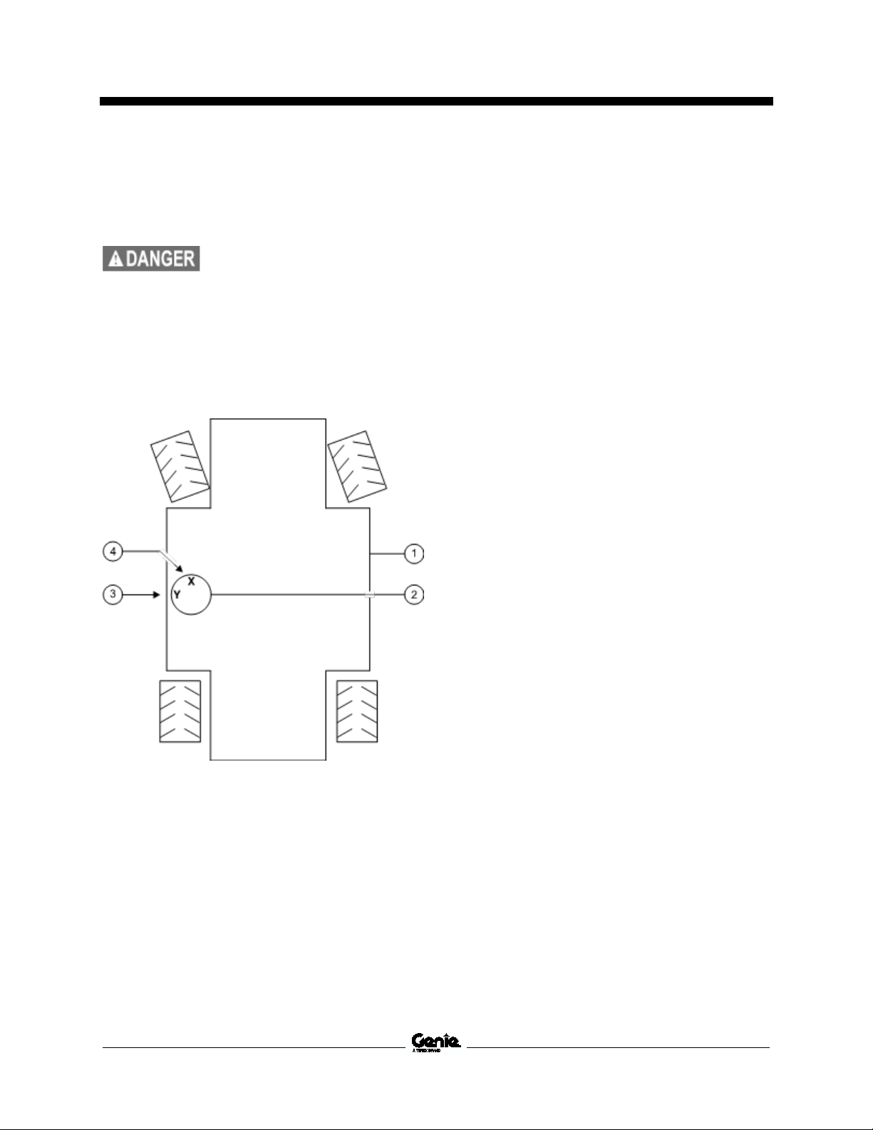
Service and Repair Manual August 2022
Tip
sensor must be installed with the
"X" on the level sensor base
towards the steer end of the
machine. Failure to install the tilt
level sensor as
result in the machine tipping
over causing death or serious
injury.
Ground Controls
5 Install the new level sensor onto the machine
with the "X" on the level sensor base towards
the steer end of the machine. Install and
tighten the level sensor retaining fasteners.
-over hazard. The tilt level
instructed could
6 Connect the wire harness to the level sensor.
7 Adjust the level sensor retaining fasteners
until the bubble in the top of the level sensor
is centered in the circles.
Note: Be sure there are threads showing through
the top of the adjusting fasteners.
8 Calibrate the new level sensor. Refer to
Repair Procedure, How to Install and
Calibrate the Level Sensor.
1 chassis
2 level sensor
3 "Y" indicator
4 "X" indicator
42 GS
™
-2669 DC • GS™-3369 DC • GS™-4069 DC Part No. 1306585GT
Page 55

August 2022 Service and Repair Manual
Tip
machine on a surface that is not
level while in Service Override
mode will result in death or
serious injury. Follow proper
operating procedures and safety
precautions. Do not use Service
Override mode if you are not
trained and fa
operation of the machine.
Ground Controls
4-6 Service O ver ride Mode
4-6
Service Override Mode
The Electronic Control Module (ECM) is
programmed with a Service Override mode.
Service Override mode is only indented for certain
circumstances and is not part of the normal
machine operation. Service Override mode should
only be accessed by trained personal to repair
faults and/ or a malfunctioning machine.
Note: Service Override mode can only be entered
at the ground controls and is intended to allow the
platform to be raised or lowered. Once the
platform has reached the maximum allowable
height, the system will exit Service Override mode.
Repeat this procedure to lower the platform.
Note: When in Service Override mode, an audible
alarm will sound.
Note: Before entering Service Override mode, fault
codes or the malfunction affecting the operation of
the machine should be fully understood to ensure
Service Override mode is required.
Note: Perform this operation on a firm, level
surface and if equipped, with the outriggers auto
leveled or fully retracted.
1 Turn the key switch to the ground controls
position and pull out the red Emergency Stop
button to the on position at the platform
controls.
2 Press and hold the ground control scroll up
and scroll down buttons.
Ground Control Menu Buttons
1 scroll down button
2 enter button
3 scroll up button
4 escape button
5 LCD display
3 Pull out the red Emergency Stop button to the
on position at the ground controls.
Part No. 1306585GT GS
-over hazard. Operating the
miliar with the
™
-2669 DC • GS™-3369 DC • GS™-4069 DC 43
Result: The ground controls LCD display will
show the following:
4 Release the Scroll Up and Scroll Down
buttons after the ground controller powers up.
Page 56

Service and Repair Manual August 2022
Ground Controls
5 At the ground controls, use the Scroll Down
button to scroll to SVC Override.
Result: The ground controls LCD display will
show the following:
6 Press the enter button.
Result: The ground controls LCD display will
show the following:
7 Press the enter button.
Result: The ground controls LCD display will
show the following:
44 GS
™
-2669 DC • GS™-3369 DC • GS™-4069 DC Part No. 1306585GT
Page 57

August 2022 Service and Repair Manual
Bodily injury hazard. Spraying
hydraulic oil can penetrate and
burn skin. Loosen hydraulic
connections very
the oil pressure to dissipate
gradually. Do not allow oil to
squirt or spray.
Component damage hazard.
After replacing the hydraulic
pump, it is critical to return the
lift and
original factory specifications.
Refer to Specifications,
Performance Specifications
Hydraulic Pump
Hydraulic Pum p
5-1 Hydraulic Pum p
5-1
Hydraulic Pump
The hydraulic pump is a single section, gear-type
pump.
Note: When removing a hose assembly or fitting,
the O-ring (if equipped) on the fitting and/or hose
end must be replaced. All connections must be
torqued to specification during installation. Refer to
Specifications, Hydraulic Hose and Fitting Torque
Specifications.
How to Test the Hy dra ul ic P um p
How to Test the Hydraulic Pump
1 Connect a 0 to 5000 psi / 0 to 350 bar
pressure gauge to test port #1 (TP1) on the
function manifold.
2 Remove the platform controls from the
platform and place the controls near the
function manifold on the tank side of the
machine.
3 Steer the machine fully to the right or left and
hold. Note the pressure reading on the
pressure gauge. Refer to Specifications,
Hydraulic Specifications.
How to Remov e th e Hy d raulic P u mp
How to Remove the Hydraulic
Pump
1 Tag, disconnect and plug the hydraulic hoses
on the pump. Cap the fittings on the pump.
slowly to allow
2 Remove the pump mounting bolts. Carefully
remove the pump.
drive speed settings to
.
Part No. 1306585GT GS
™
-2669 DC • GS™-3369 DC • GS™-4069 DC 45
Page 58

Service and Repair Manual August 2022
Hydraulic Pump
How to Cali brat e th e Hyd rauli c P ump
How to Calibrate the Hydraulic
Pump
1 Turn the key switch to the ground controls
position and pull out the red Emergency Stop
button to the on position at the platform
controls.
2 Press and hold the ground control scroll up
and scroll down buttons.
4 Release the Scroll Up and Scroll Down
buttons after the ground controller powers up.
5 At the ground controls, use the Scroll Up or
Scroll Down buttons to scroll to Select Option.
6 Press the Enter button.
7 Use the Scroll Up or Scroll Down buttons to
scroll to Select Option Pump Efficiency.
Ground Control Menu Buttons
1 scroll down button
2 enter button
3 scroll down button
4 escape button
5 LCD display
3 Pull out the red Emergency Stop button to the
on position at the ground controls.
Result: The ground controls LCD display will
show the following:
8 Press the Enter button.
Result: The ground controls LCD display will
show the following:
9 Press the Scroll Down button.
Result: The ground controls LCD display will
show the following:
46 GS
™
-2669 DC • GS™-3369 DC • GS™-4069 DC Part No. 1306585GT
Page 59

August 2022 Service and Repair Manual
Hydraulic Pump
10 Press the Enter button.
Result: The ground controls LCD display will
show the following:
11 Press and Hold the Enter button.
Result: The ground controls LCD display will
scroll through the following screens.
Note: Continue to hold the Enter button until
calibration is complete. If the Enter button is
released, return to step 10 and repeat this
procedure.
Result: The ground controls LCD displays the
following screen. Calibration data is within
range.
Note: The screen will return to the options screen
after 2 seconds.
Result: The ground controls LCD displays the
following screen. Calibration data is not within
range. The pump needs to be repaired or
replaced.
12 For a bad result, press the Enter button to
return to the option screen
13 Push in the red Emergency Stop button to the
off position.
Part No. 1306585GT GS
™
-2669 DC • GS™-3369 DC • GS™-4069 DC 47
Page 60

Service and Repair Manual August 2022
Index
No.
Description
Function Torque
1 Relief valve
Oscillate relief
lbs / 27 Nm
2 Accumulator
Oscillate circuit
lbs / 15 Nm
3 Relief
(GS 2669
(GS 3369
(GS 4069
Lift circuit
lbs / 27 Nm
4 Check valve
Oscillate circuit
lbs / 27 Nm
5
Proportional relief valve
100
FH
System relief
lbs / Nm
6 Relief valve, 150
Steer circuit
20 ft-lbs / 27 Nm
7 Check valve
Load sense
lbs / 27 Nm
8 Flow control valve
Controls flow to the steer circuit
lbs / 27 Nm
9
Solenoid valve, 3 position 5 way
FL
Steer circuit
lbs / 27 Nm
Check valve
10 Flow control valve,
Controls flow to the oscillate
circuit
lbs / 27 Nm
11
Solenoid Valve, 2 position 3 way
FF
Oscillate circuit
lbs / 27 Nm
12 Pressure switch
Oscillate / Accumulator
lbs / 15 Nm
13 Solenoid Valve,
Oscillate / Accumulator
20 ft-lbs / 27 Nm
Orifice
Oscillate / Accumulator
14 Solenoid Valve,
Oscillate right
lbs / 27 Nm
15
Solenoid Valve, 2 position 3 way
FO
Lift circuit
lbs / 27 Nm
16 Solenoid Valve,
Oscillate left
lbs / 27 Nm
Manifolds
Manifol ds
6-1 Function Manifold C ompone nts
6-1
Function Manifold Components
The function manifold is located inside the hydraulic compartment.
FQ
FE
valve
Schematic
Item
FD
20 ft-
11 ft-
20 ft-
- 3100 psi / 214 bar)
- 2900 psi / 200 bar)
- 2850 psi / 197 bar)
FA
20 ft-
25 ft-
- 3500 psi / 7 - 24 bar
0 psi / 103 bar FI
FJ
2 gpm / 7,6 L/min FK
20 ft-
20 ft-
20 ft-
FM
1 gpm / 3,8 L/min FG
20 ft-
20 ft-
FN
2 position 3 way FB
FC
11 ft-
48 GS
2 position 3 way FP
2 position 3 way FR
™
-2669 DC • GS™-3369 DC • GS™-4069 DC Part No. 1306585GT
20 ft-
20 ft-
20 ft-
Page 61

August 2022 Service and Repair Manual
Manifolds
Part No. 1306585GT GS
™
-2669 DC • GS™-3369 DC • GS™-4069 DC 49
Page 62

Service and Repair Manual August 2022
Manifolds
6-2 Valve Adjust ments - Fu nction Ma ni fold
6-2
Valve Adjustments - Function
Manifold
How to Check t he S yst e m Pr opo rtion al Reli ef Val ve
How to Check the System
Proportional Relief Valve
Note: Perform this procedure with the machine in
the stowed position.
1 Connect a 0 to 5000 psi / 0 to 350 bar
pressure gauge to test port #1 (TP1) on the
function manifold.
2 Remove the platform controls from the
platform and place the controls near the
function manifold on the hydraulic tank side of
the machine.
6 Remove the pressure gauge.
3 Remove the coil from the platform up valve.
Do not disconnect the harness from the coil.
4 Turn the key switch to platform control and
pull out the red Emergency Stop button to the
on position at both the ground and platform
controls.
5 Press and hold the enable and platform up
buttons OR select the platform function button
and activate platform up. Note the pressure
reading on the pressure gauge. Refer to
Specifications, Hydraulic Components
Specifications.
Result: If the pressure reading is not within
range, replace the proportional relief valve.
1 test port #1
2 proportional relief valve
3 platform up valve
50 GS
™
-2669 DC • GS™-3369 DC • GS™-4069 DC Part No. 1306585GT
Page 63

August 2022 Service and Repair Manual
Tip
the relief valve higher than
specified.
Manifolds
How to Adjust the Oscillate Relief Valve
How to Adjust the Oscillate Relief
Valve
Note: Perform this procedure with the machine in
the stowed position and in high torque mode.
1 Connect a 0 to 5000 psi / 0 to 350 bar
pressure gauge to test port #2 (TP2) on the
function manifold.
2 Disconnect the harness from the oscillate
supply coil and the steer right coil.
3 Connect the oscillate supply harness to the
steer right coil and the steer right harness to
the oscillate supply coil.
4 Disconnect the harness from the proportional
relief valve.
5 Turn the key switch to platform control and
pull out the red Emergency Stop button to the
on position at both the ground and platform
controls.
11 Remove the pressure gauge.
6 Steer the machine to the right and hold. Note
the pressure readings on the pressure gauge.
Refer to Specifications, Hydraulic
Components Specifications.
7 Use a wrench to hold the oscillate relief valve
and remove the cap.
8 Adjust the internal hex socket. Turn it
clockwise to increase the pressure or
counterclockwise to decrease the pressure.
Install the relief valve cap.
-over hazard. Do not adjust
9 Repeat this procedure beginning with step
5 to confirm the relief valve pressure.
10 Connect the harness back to the original
position.
1 test port #2
2 oscillate supply coil
3 steer right coil
4 oscillate relief valve
5 proportional relief valve
Part No. 1306585GT GS
™
-2669 DC • GS™-3369 DC • GS™-4069 DC 51
Page 64

Service and Repair Manual August 2022
Tip
the relief valve higher than
specified.
Manifolds
How to Adjus t th e St ee r Relie f Valv e
How to Adjust the Steer Relief
Valve
Note: Perform this procedure with the machine in
the stowed position.
1 Connect a 0 to 5000 psi / 0 to 350 bar
pressure gauge to test port #1 (TP1) on the
function manifold.
2 Disconnect the harness from the proportional
relief valve.
3 Remove the platform controls from the
platform and place the controls near the
function manifold on the hydraulic tank side of
the machine.
4 Turn the key switch to platform control and
pull out the red Emergency Stop button to the
on position at both the ground and platform
controls.
10 Remove the pressure gauge.
5 Steer the machine fully to the right or left and
hold. Note the pressure reading on the
pressure gauge. Refer to Specifications,
Hydraulic Components Specifications.
6 Use a wrench to hold the steer relief valve
and remove the cap.
7 Adjust the internal hex socket. Turn it
clockwise to increase the pressure or
counterclockwise to decrease the pressure.
Install the relief valve cap.
-over hazard. Do not adjust
8 Repeat this procedure beginning with step
4 to confirm the relief valve pressure.
9 Connect the harness to the proportional relief
valve.
1 test port #1
2 steer relief valve
3 proportional relief valve
52 GS
™
-2669 DC • GS™-3369 DC • GS™-4069 DC Part No. 1306585GT
Page 65

August 2022 Service and Repair Manual
Manifolds
How to Adjus t th e Pl atfo rm U p Rel ie f V alve
How to Adjust the Platform Up
Relief Valve
Note: Verify the hydraulic oil level is within the top
2 inches / 5 cm of the sight gauge.
1 Connect a 0 to 5000 psi / 0 to 350 bar
pressure gauge to test port #1 (TP1) on the
function manifold.
3 Press and hold the ground control scroll up
and scroll down buttons.
Ground Control Menu Buttons
1 scroll down button
2 enter button
3 scroll down button
4 escape button
5 LCD display
4 Pull out the red Emergency Stop button to the
on position at the ground controls.
1 platform up relief valve
2 test port #1
2 Turn the key switch to the ground controls
position and pull out the red Emergency Stop
button to the on position at the platform
controls.
Result: The ground controls LCD display will
show the following:
5 Release the Scroll Up and Scroll Down
buttons after the ground controller powers up.
Part No. 1306585GT GS
™
-2669 DC • GS™-3369 DC • GS™-4069 DC 53
Page 66

Service and Repair Manual August 2022
Manifolds
6 At the ground controls, use the Scroll Down
button to scroll to SELECT OPTION.
Result: The ground controls LCD display will
show the following:
Note: After 1 second the display will return to
SELECT OPTION, PLAT. OVERLOAD.
10 Press the Scroll Down button to scroll to
Down Delay.
7 Press the enter button.
Result: The ground controls LCD display will
show the following:
8 Press the enter button.
Result: The ground controls LCD display will
show the following:
9 Press the enter button.
Result: The ground controls LCD display will
show the following:
Result: The ground controls LCD display will
show the following:
11 Press the enter button.
Result: The ground controls LCD display will
show the following:
12 Press the enter button.
Result: The ground controls LCD display will
show the following:
54 GS
™
-2669 DC • GS™-3369 DC • GS™-4069 DC Part No. 1306585GT
Page 67

August 2022 Service and Repair Manual
GS-2669
g
GS-3369
g
GS-4069
g
Tip
adjust the relief valves to
specification could result in the
machine tipping over, causing
death or serious injury. Do not
adjust the relief valve pressures
higher than specifications.
Manifolds
Note: After 1 second the display will return to
SELECT OPTION, DOWN DELAY.
13 Push in the red Emergency Stop button to the
off position.
14 Pull out the red Emergency Stop button to the
on position and raise the platform
approximately 10 feet / 3 m.
15 Lift the safety arm, move it to the center of the
scissor arm and rotate down to a vertical
position.
16 Lower the platform onto the safety arm.
17 Push in the red Emergency Stop button to the
off position.
18 Locate and disconnect the lift cylinder
pressure sensor harness.
22 Using a suitable lifting device, place and
secure the maximum rated load in the center
of the platform deck.
1500 lbs / 680 k
1000 lbs / 454 k
800 lbs / 363 k
23 Press the lift function enable button. Fully
elevate the platform, then continue activating
the lift function while observing the pressure
reading on the pressure gauge. Note the
pressure. Refer to Specifications, Hydraulic
Component Specifications.
24 Hold the lift relief valve (item 1) with a wrench
and remove the cap.
25 Adjust the internal hex socket. Turn it
clockwise to increase the pressure or
counterclockwise to decrease the pressure.
Install the relief valve cap.
-over hazard. Failure to
1 solenoid valve
2 lift cylinder
3 Pressure sensor
19 Pull out the red Emergency Stop button to the
on position and raise the platform
approximately 10 feet / 3 m.
20 Return the safety arm to the stowed position.
21 Lower the platform to the stowed position.
Part No. 1306585GT GS
26 Repeat this procedure beginning with step
22 to confirm the relief valve pressure.
27 Lower the platform to the stowed position.
28 Remove the weight from the platform.
29 Raise the platform approximately 10 feet /
3 m.
™
-2669 DC • GS™-3369 DC • GS™-4069 DC 55
Page 68

Service and Repair Manual August 2022
Manifolds
30 Lift the safety arm, move it to the center of the
scissor arm and rotate down to a vertical
position.
31 Lower the platform onto the safety arm.
32 Push in the red Emergency Stop button to the
off position.
33 Connect the harness to the lift cylinder
pressure sensor.
34 Pull out the red Emergency Stop button to the
on position and raise the platform
approximately 10 feet / 3 m.
35 Return the safety arm to the stowed position.
36 Lower the platform to the stowed position.
37 Push in the red Emergency Stop button to the
off position.
38 Press and hold the ground control scroll up
and scroll down buttons.
41 At the ground controls, use the Scroll Down
button to scroll to SELECT OPTION.
Result: The ground controls LCD display will
show the following:
42 Press the enter button.
Result: The ground controls LCD display will
show the following:
43 Press the enter button.
39 Pull out the red Emergency Stop button to the
on position at the ground controls.
Result: The ground controls LCD display will
show the following:
40 Release the Scroll Up and Scroll Down
buttons after the ground controller powers up.
Result: The ground controls LCD display will
show the following:
44 Press the enter button.
Result: The ground controls LCD display will
show the following:
56 GS
™
-2669 DC • GS™-3369 DC • GS™-4069 DC Part No. 1306585GT
Page 69
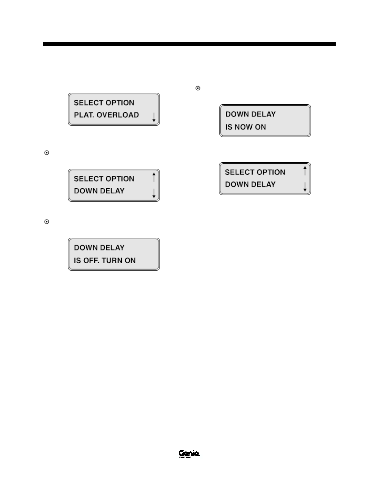
August 2022 Service and Repair Manual
Manifolds
Note: After 1 second the display will return to
SELECT OPTION, PLAT. OVERLOAD.
47 Press the enter button.
Result: The ground controls LCD display will
show the following:
45 Press the Scroll Down button to scroll to
Down Delay.
Result: The ground controls LCD display will
show the following:
46 Press the enter button.
Result: The ground controls LCD display will
show the following:
Note: After 1 second the display will return to
SELECT OPTION, DOWN DELAY.
48 Push in the red Emergency Stop button to the
off position.
49 Test the platform overload system. Refer to
the appropriate Maintenance Manual and
procedure for your machine, Test the Platform
overload System.
Part No. 1306585GT GS
™
-2669 DC • GS™-3369 DC • GS™-4069 DC 57
Page 70

Service and Repair Manual August 2022
Index
No.
Description
Function Torque
1
Solenoid valve, 3 position 4 way
BA
Outriggers extend / retract
lbs / 54 Nm
Manifolds
6-3 Outrigge r Mani fold C ompon ent s
6-3
Outrigger Manifold Components
The outrigger manifold is located inside the hydraulic compartment.
Schematic
Item
40 ft-
58 GS
™
-2669 DC • GS™-3369 DC • GS™-4069 DC Part No. 1306585GT
Page 71

August 2022 Service and Repair Manual
Electrocution/burn hazard.
Contact with electrically charged
circuits could result in death or
seriou
watches and other jewelry.
Description
Specification
Solenoid valve, 3 position 5 way
Manifolds
6-4 Valve Coils
6-4
Valve Coils
How to Test a Coil
A properly functioning coil provides an
electromagnetic force which operates the solenoid
valve. Critical to normal operation is continuity
within the coil. Zero resistance or infinite
resistance indicates the coil has failed.
Valve Coil Resistance
Specification
Note: The following coil resistance specifications
are at an ambient temperature of 68°F / 20°C. As
valve coil resistance is sensitive to changes in air
temperature, the coil resistance will typically
increase or decrease by 4% for each 18°F / 20°C
that your air temperature increases or decreases
from 68°F / 20°C.
Since coil resistance is sensitive to temperature,
resistance values outside specification can
produce erratic operation. When coil resistance
decreases below specification, amperage
increases. As resistance rises above specification,
voltage increases.
While valves may operate when coil resistance is
outside specification, maintaining coils within
specification will help ensure proper valve function
over a wide range of operating temperatures.
s injury. Remove all rings,
Note: If the machine has been in operation, allow
the coil to cool at least 3 hours before performing
this test.
1 Tag and disconnect the wiring from the coil to
be tested.
2 Test the coil resistance using a multimeter set
to resistance (Ω). Refer to the Valve Coil
Resistance Specification table.
Solenoid valve, 2 position 2 way
24V DC with diode
(schematic items CA, CB, CC, CD,
CE, CF)
Solenoid valve, 2 position 3 way
24V DC with diode
(schematic items BA, FB, FF, FO, FP,
FR, )
24V DC with diode (schematic item
FL)
25Ω
35Ω
35Ω
Result: If the resistance is not within the
adjusted specification, plus or minus 10%,
replace the coil.
Part No. 1306585GT GS
™
-2669 DC • GS™-3369 DC • GS™-4069 DC 59
Page 72
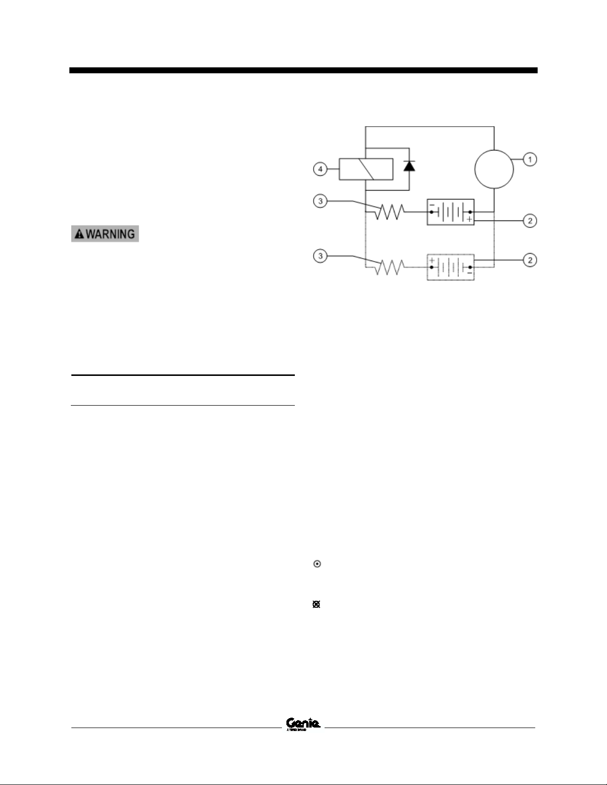
Service and Repair Manual August 2022
Electrocution/burn hazard.
Contact with electrically charged
circuits could result in death or
serious injury. Remove all rings,
watches and other jewelry.
Resistor 10
Genie part number 27287
Manifolds
How to Test a Coil Diode
Properly functioning coil diodes protect the
electrical circuit by suppressing voltage spikes.
Voltage spikes naturally occur within a function
circuit following the interruption of electrical current
to a coil. Faulty diodes can fail to protect the
electrical system, resulting in a tripped circuit
breaker or component damage.
1 Test the coil for resistance. Refer to Repair
Procedure, How to Test a Coil.
2 Connect a 10W resistor to the negative
terminal of a known good 9V DC battery.
Connect the other end of the resistor to a
terminal on the coil.
Ω
Note: The battery should read 9V DC or more
when measured across the terminals.
1 multimeter
2 9v DC battery
3 10Ω resistor
4 coil
Note: Dotted lines in illustration indicate a reversed
connection as specified in step 6.
3 Set a multimeter to read DC current.
Note: The multimeter, when set to read DC
current, should be capable of reading up to
800 mA.
60 GS
4 Connect the negative lead to the other
terminal on the coil.
5 Momentarily connect the positive lead from
the multimeter to the positive terminal on the
9V DC battery. Note and record the current
reading.
6 At the battery or coil terminals, reverse the
connections. Note and record the current
reading.
Result: Both current readings are greater than
0 mA and are different by a minimum of 20%.
The coil is good.
Result: If one or both of the current readings
are 0 mA, or if the two current readings do not
differ by a minimum of 20%, the coil and/or its
internal diode are faulty and the coil should be
replaced.
™
-2669 DC • GS™-3369 DC • GS™-4069 DC Part No. 1306585GT
Page 73

August 2022 Service and Repair Manual
Component damage hazard. The
work area and surfaces where
this procedure will be performed
must be clean and free of debris
th
system and cause severe
component damage. Dealer
service is recommended.
Bodily injury hazard. Spraying
hydraulic oil can
burn skin. Loosen hydraulic
connections very slowly to allow
the oil pressure to dissipate
gradually. Do not allow oil to
squirt or spray.
Component damage hazard.
During installation, do not
overtighten the hydraulic tank
strap mounting fastener.
Hydraulic Tank
Hydrau lic Ta nk
7-1 Hydraulic Tank
7-1
Hydraulic Tank
The primary functions of the hydraulic tank is to
cool, clean and deaerate the hydraulic fluid during
operation. It utilizes internal suction strainer for the
pump supply line.
How to Remove the Hydraulic
Tank
at could get into the hydraulic
Note: When removing a hose assembly or fitting,
the O-ring (if equipped) on the fitting and/or hose
end must be replaced. All connections must be
torqued to specification during installation. Refer to
Specifications, Hydraulic Hose and Fitting Torque
Specifications.
3 Tag and disconnect the harnesses from the
ground control box.
4 Remove the ground control box from the
machine and set aside.
5 Tag, disconnect and plug the hydraulic hoses
from the hydraulic tank. Cap the fittings on the
tank.
6 Loosen the hydraulic tank mounting strap
fastener. Pull the tank strap to the side.
Note: Do not remove the tank strap.
7 Remove the hydraulic tank from the machine.
Note: Clean the hydraulic tank and inspect for
cracks or other damage before installing.
1 Remove the hydraulic tank cap.
2 Remove the drain plug from the hydraulic tank
and completely drain the tank into a container
of suitable capacity. Refer to Specifications,
Machine Specifications.
Part No. 1306585GT GS
penetrate and
™
-2669 DC • GS™-3369 DC • GS™-4069 DC 61
Page 74

Service and Repair Manual August 2022
Crushing hazard. The chassis
will fall if not properly supported.
Steer Axle Components
Steer Axle C omp onen ts
8-1 Yoke Asse mbly
8-1
Yoke Assembly
How to Remove the Yoke
Assembly
1 Chock both sides of the wheels at the non-
steer end of the machine.
2 Center a lifting jack under the drive chassis at
the steer end of the machine.
3 Loosen the wheel lug nuts. Do not remove
them.
4 Raise the machine approximately 2 inches /
5 cm. Place blocks under the chassis for
support.
5 Remove the wheel lug bolts. Remove the tire
and wheel assembly.
6 Support and secure the yoke and assembly
with a lifting device.
Left side yoke:
7 Remove the retaining fasteners from the tie
rod pivot pin.
1 upper king pin
2 tie rod pivot pin
3 lower king pin
4 steer sensor assembly
5 yoke assembly
8 Use a small pry bar to move the pivot pin
down enough to clear the steer sensor
assembly.
62 GS
9 Remove the steer sensor actuator and spring
from the tie rod pivot pin and set aside.
10 Remove the steer sensor assembly and set it
aside.
11 Using a soft metal drift pin and a mallet, drive
the pivot pin up to remove it.
™
-2669 DC • GS™-3369 DC • GS™-4069 DC Part No. 1306585GT
Page 75

August 2022 Service and Repair Manual
Crushing hazard. The assembly
may become unbalanced and fall
if not properly supported and
secured with a suitable lifting
device when it is removed from
the machine.
Crushing hazard. The assembly
may become unbalanced and fall
if not properly supported and
secured with a
device when it is removed from
the machine.
Component damage hazard.
Repairs to the motor should only
be performed by an authorized
dealer.
Component damage hazard. The
work area and surfaces
this procedure will be performed
must be clean and free of debris
that could get into the hydraulic
system and cause severe
component damage. Dealer
service is recommended.
Steer Axle Components
12 Remove the retaining fastener from the lower
yoke king pin.
How to Remove a Drive Motor
13 Use a small pry bar to remove the king pin.
14 Remove the retaining fastener from the upper
yoke king pin.
15 Use a small pry bar to remove the king pin.
16 Remove the yoke assembly from the
machine.
Right side yoke:
17 Remove the steer cylinder rue ring and clevis
pin from the yoke and set aside.
18 Remove the tie rod rue ring and clevis pin
from the yoke and set aside.
19 Remove the retaining fastener from the lower
yoke king pin.
20 Use a small pry bar to remove the king pin.
where
Note: When removing a hose assembly or fitting,
the O-ring (if equipped) on the fitting and/or hose
end must be replaced. All connections must be
torqued to specification during installation. Refer to
Specifications, Hydraulic Hose and Fitting Torque
Specifications.
1 Refer to Repair Procedure, How to Remove
the Yoke.
2 Remove the drive motor mounting fasteners.
Remove the drive motor from the yoke.
21 Remove the retaining fastener from the upper
yoke king pin.
22 Use a small pry bar to remove the king pin.
23 Remove the yoke assembly from the
machine.
Part No. 1306585GT GS
suitable lifting
™
-2669 DC • GS™-3369 DC • GS™-4069 DC 63
Page 76

Service and Repair Manual August 2022
Bodily injury hazard. Spraying
hydraulic oil can penetrate and
burn skin. Loosen hydraulic
connections very slowly to allow
the oil pressur
gradually. Do not allow oil to
squirt or spray.
Steer Axle Components
8-2 Steer Cyli nde r
8-2
Steer Cylinder
8-3 Tie Rod
8-3
Tie Rod
How to Remove the Steer
Cylinder
Note: When removing a hose assembly or fitting,
the O-ring (if equipped) on the fitting and/or hose
end must be replaced. All connections must be
torqued to specification during installation. Refer to
Specifications, Hydraulic Hose and Fitting Torque
Specifications.
1 Tag, disconnect and plug the hydraulic hoses
from the steer cylinder. Cap the fittings on the
cylinder.
e to dissipate
2 Remove the rue ring from each cylinder clevis
pin. Remove the clevis pins.
3 Remove the steer cylinder from the machine.
How to Remove the Tie Rod
1 Remove the rue ring from the clevis pin
connecting the tie rod to the right side yoke
assembly. Remove the clevis pin.
1 clevis pin
2 pivot pin
3 steer sensor assembly
4 tie rod
2 Remove the retaining fasteners from the pivot
5 rue ring
pin connecting the tie rod to the left side yoke
assembly.
64 GS
3 Use a small pry bar to move the pivot pin
down enough to clear the steer sensor
assembly.
4 Remove the steer sensor actuator and spring
from the tie rod pivot pin and set aside.
5 Remove the steer sensor assembly and set it
aside.
6 Using a soft metal drift pin and a mallet, drive
the pivot pin up to remove it.
7 Remove the tie rod.
™
-2669 DC • GS™-3369 DC • GS™-4069 DC Part No. 1306585GT
Page 77

August 2022 Service and Repair Manual
Bodily injury hazard. Spraying
hydraulic oil can penetrate and
burn skin. Loosen hydraulic
connections very slowly to allow
the oil pressure to dissipate
gradually. Do not allow oil to
squirt or spray.
Steer Axle Components
8-4 Oscillate Cyl i nde r
8-4
Oscillate Cylinder
8-5 Oscillate H oses
8-5
Oscillate Hoses
How to Remove the Oscillate
Cylinder
Note: When removing a hose assembly or fitting,
the O-ring (if equipped) on the fitting and/or hose
end must be replaced. All connections must be
torqued to specification during installation. Refer to
Specifications, Hydraulic Hose and Fitting Torque
Specifications.
1 Tag, disconnect and plug the hydraulic hoses
from the oscillate cylinder. Cap the fittings on
the cylinder.
2 Chock both sides of the wheels at the non-
steer end of the machine.
3 Center a lifting jack under the drive chassis
just behind the front axle on the side of the
machine the cylinder is being removed from.
Test the Oscillate Axle Hose
Routing
Note: Perform this procedure if the oscillate hoses
have been removed or replaced.
1 Open the ground controls compartment and
locate the function manifold.
4 Remove the pivot pin retaining fasteners.
5 Using a soft metal drift, remove the pivot pin.
Note: Adjust the lifting jack to reduce the load on
the pivot pins. Do not lift the machine off of the
ground.
6 Remove the oscillate cylinder from the
machine.
Part No. 1306585GT GS
™
-2669 DC • GS™-3369 DC • GS™-4069 DC 65
1 function manifold
Page 78

Service and Repair Manual August 2022
Steer Axle Components
2 Disconnect the connector with the green/black
wire from the oscillate right coil (item 2) and
swap it with the connector with the blue wire
from the steer right coil (item 3).
4 Turn the key switch to platform control and
pull out the red Emergency Stop button to the
on position at both the ground and platform
controls.
5 Slowly drive the machine in a safe direction
and activate steer right.
Result: The right oscillate cylinder will extend
and the left oscillate cylinder will retract.
6 Slowly drive the machine in a safe direction
and activate steer left.
7 Turn the key switch to the off position.
8 Swap the connectors back to the correct coils
using steps 2 an 3 as a reference. Continue to
Check the Steering.
1 Green
2 Green / Black
3 Blue
4 Blue / Black
3 Disconnect the connector with the green wire
from the oscillate left coil (item 1) and swap it
with the connector with the blue/black wire
from the steer left coil (item 4).
Check the Steering
1 Turn the key switch to platform control and
pull out the red Emergency Stop button to the
on position at both the ground and platform
controls.
2 Activate steer right and verify the machine
steers to the right.
3 Activate steer left and verify the machine
steers to the left.
4 Test the axle oscillate. Refer to Maintenance
Section, Test the Oscillate Axle.
66 GS
™
-2669 DC • GS™-3369 DC • GS™-4069 DC Part No. 1306585GT
Page 79

August 2022 Service and Repair Manual
Steer Axle Components
8-6 Steer Angl e Se nsor
8-6
Steer Angle Sensor
How to Replace the Steer Angle
Sensor
The steer angle sensor, installed on the steer
yoke, is monitored by the control system to
determine steer angle. The control system uses
the steer angle input, along with pre-programmed
parameters, to vary the speed of each drive motor
while steering to minimize tire scrub and to help
minimize turning radius. Drive speed is also
reduced proportionately depending on the steer
angle to minimize lateral platform acceleration.
1 Adjust the steer tires so they are in a straight
driving position.
2 Turn the key switch to the off position.
3 Push in the red Emergency Stop button to the
off position at both the ground and platform
controls and turn the key switch to the off
position.
4 Remove the cable clamp securing the steer
sensor cable to the chassis.
5 Tag and disconnect the steer sensor harness
from the main harness.
6 Remove the steer sensor cover.
7 Remove the tie rod pivot pin retaining
fasteners.
1 left yoke assembly
2 steer sensor cover
3 compression spring
4 steer sensor actuator
5 tie rod pivot pin
8 Use a small pry bar to move the pivot pin
down enough to clear the steer sensor
assembly.
9 Remove the steer sensor actuator and spring
from the tie rod pivot pin and set aside.
Part No. 1306585GT GS
Note: Inspect the steer sensor actuator to make
sure it is not broken or twisted.
™
-2669 DC • GS™-3369 DC • GS™-4069 DC 67
Page 80

Service and Repair Manual August 2022
Steer Axle Components
10 Remove the steer sensor assembly retaining
fasteners. Remove the steer sensor assembly
from the yoke.
11 Set the spacer plate aside.
12 Pull the sensor harness through the cable
restraint and sensor bracket.
13 Remove the retaining fasteners that secure
the steer sensor and the sensor spacer to the
mounting plate. Remove the steer sensor.
14 Install the new steer sensor.
15 Install the steer sensor assembly to the yoke.
16 Rotate the tie rod pivot pin until it is
approximately 90° from the mounting tab on
the tie rod.
1 steer sensor cover
2 spacer plate
3 steer sensor bracket
4 cable restraint
5 steer sensor
6 steer sensor spacer
7 steer sensor mounting plate
68 GS
™
-2669 DC • GS™-3369 DC • GS™-4069 DC Part No. 1306585GT
Page 81

August 2022 Service and Repair Manual
Steer Axle Components
17 Install the steer sensor actuator onto the tie
rod pivot pin.
18 Insert the compression spring into the steer
sensor and push the tie rod pivot pin up until
the actuator hex pin is engaged into the steer
sensor.
Note: Be sure the sensor actuator hex pin is
engaged into the sensor.
19 Rotate the tie rod pivot pin counterclockwise
approximately 90° and secure it to the tie rod.
20 Install the steer sensor cover.
21 Connect the steer sensor harness to the main
harness and secure with the cable clamp.
22 Calibrate the steer sensor. Refer to Repair
Procedure, How to Calibrate the Steer Angle
Sensor.
How to Calibrate the Steer Angle
Sensor
1 Turn the key switch to the ground controls
position and pull out the red Emergency Stop
button to the on position at the platform
controls.
2 Press and hold the ground control scroll up
and scroll down buttons.
1 scroll down button
2 enter button
3 scroll up button
4 escape button
5 LCD display
3 Pull out the red Emergency Stop button to the
on position at the ground controls.
Result: The ground controls LCD display will
show the following:
Part No. 1306585GT GS
™
-2669 DC • GS™-3369 DC • GS™-4069 DC 69
Page 82

Service and Repair Manual August 2022
Steer Axle Components
4 Release the Scroll Up and Scroll Down
buttons after the ground controller powers up.
5 At the ground controls, use the Scroll Down
button to scroll to SELECT OPTION.
10 Press the enter button.
Result: The ground controls LCD display will
show the following:
Note: The platform controls do not have to be
connected at the chassis ground controls.
6 Press the enter button.
7 Use the Scroll Up or Scroll Down buttons to
scroll to Select Option Steer Sensor.
8 Press the enter button.
Result: The ground controls LCD display will
show the following:
Note: Do not press the Enter button. Pressing the
Enter button will disable the steer sensor.
9 Use the Scroll Up or Scroll Down buttons to
scroll to Calibrate Steer Sensor.
11 Press the enter button.
Result: The ground controls LCD display will
show the following:
12 Use the platform drive controller steer function
to align the steer tires with the drive chassis.
70 GS
™
-2669 DC • GS™-3369 DC • GS™-4069 DC Part No. 1306585GT
Page 83

August 2022 Service and Repair Manual
Steer Axle Components
13 Press the enter button.
Result: The ground controls LCD display will
show the following:
14 Use the platform drive controller steer function
to turn the steer tires fully to the right.
15 Press the enter button.
Result: The ground controls LCD display will
show the following:
16 Use the platform drive controller steer function
to turn the steer tires fully to the left.
17 Press the enter button.
Result: The ground controls LCD display will
show the following:
Note: If any screens other than the one shown is
displayed, repeat this procedure. If the problem
persist, contact your local Genie Product Support.
18 Push in the red Emergency Stop button to the
off position.
Part No. 1306585GT GS
™
-2669 DC • GS™-3369 DC • GS™-4069 DC 71
Page 84
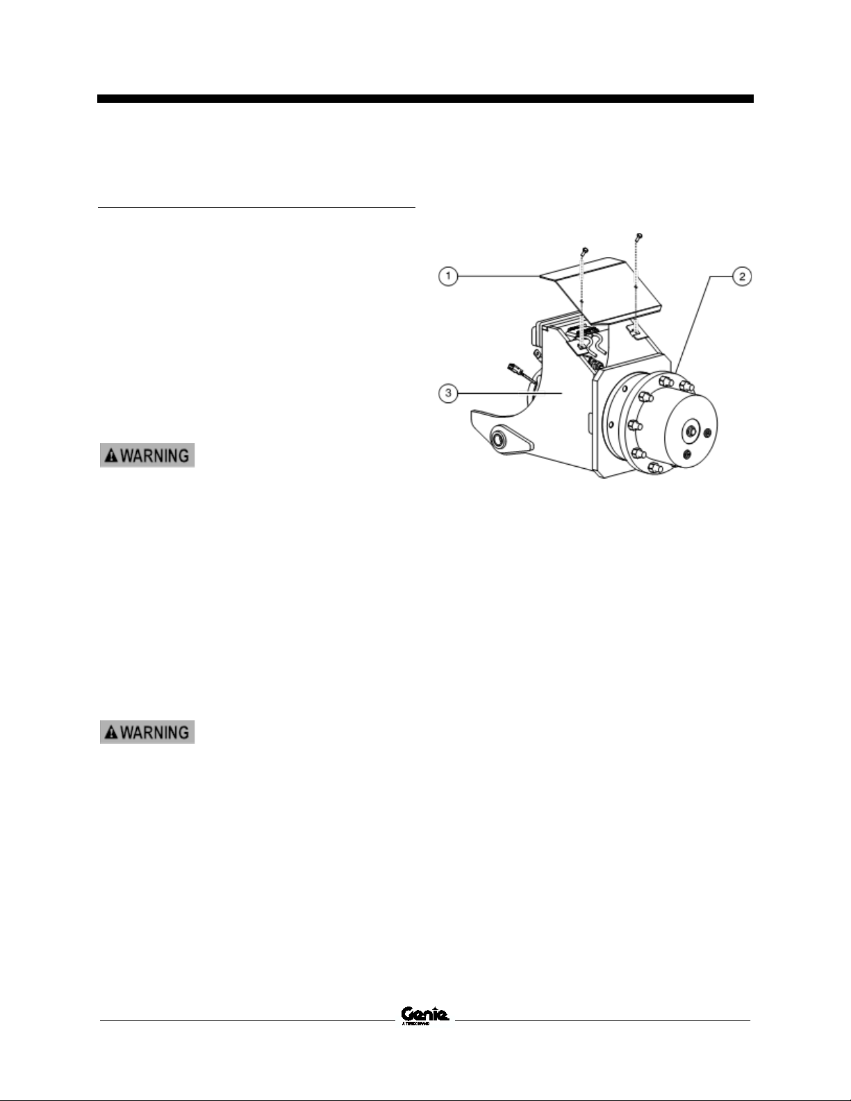
Service and Repair Manual August 2022
Electrocution/burn hazard.
Contact with electrically charged
circuits could result in dea
serious injury. Remove all rings,
watches and other jewelry.
Crushing hazard. The chassis
will fall if not properly supported.
Non-steer Axle Components
Non-steer Axle Com p onen ts
9-1 Drive Moto rs
9-1
Drive Motors
How to Remove a Drive Motor
The drive motors are AC powered and are a
brushless design requiring very little maintenance.
They have built-in speed and temperature sensors
which is monitored by the ground controls
(GCON). The speed sensor is a Hall-effect type
and is part of the rear motor shaft bearing. The
temperature switch will shut down the drive motor
if it becomes excessively hot.
1 Disconnect the battery pack from the
machine.
th or
2 Chock both sides of the wheels at the steer
end of the machine.
3 Center a lifting jack under the drive chassis at
the non-steer end of the machine.
4 Loosen the wheel lug nuts. Do not remove
them.
5 Raise the machine approximately 2 inches /
5 cm. Place blocks under the chassis for
support.
6 Remove the wheel lug bolts. Remove the tire
and wheel assembly.
7 Remove the axle cover.
1 axle cover
2 drive hub
3 axle assembly
8 Tag and disconnect the electrical connectors
for the brake, speed and temperature sensors
at the drive motor.
9 Tag and disconnect the electrical connectors
for the oscillate limit switches.
10 Tag and disconnect the drive motor power
cables from the motor controller in the ground
controls compartment.
Note: The power cables will have to be pulled
through the drive chassis when the axle assembly
is removed.
72 GS
™
-2669 DC • GS™-3369 DC • GS™-4069 DC Part No. 1306585GT
Page 85

August 2022 Service and Repair Manual
Non-steer Axle Components
11 Using a suitable supporting device, secure the
rear axle assembly. Do not apply pressure.
1 axle pivot pin
2 retaining fasteners
3 axle assembly
12 Remove the axle pivot pin retaining fasteners.
13 Using a soft metal drift, remove the axle pivot
pin. Remove the axle assembly from the
machine.
14 Remove the retaining fasteners that secure
the drive motor to the drive hub.
15 Support and slide the drive motor shaft out of
the drive hub. Remove the drive motor from
the machine.
1 axle assembly
2 drive hub
3 retaining fasteners (x4)
Part No. 1306585GT GS
4 drive motor
™
-2669 DC • GS™-3369 DC • GS™-4069 DC 73
Page 86

Service and Repair Manual August 2022
Component damage hazard.
Repairs to the drive hub should
only be performed by an
authorized dealer.
Crushing hazard. The drive hub
may become unbalanced and fall
if not properly supported and
secured with a suitable lifting
device when removed fr
machine.
Non-steer Axle Components
9-2 Drive Hub
9-2
Drive Hub
How to Remove a Drive Hub
1 Remove the drive motor. Refer to Repair
Procedure, How to Remove a Drive Motor.
2 Using a suitable supporting device, secure the
drive hub. Do not apply pressure.
3 Remove the drive hub retaining fasteners.
Remove the drive hub.
om the
Note: There is an O-ring between the drive motor
and drive hub. Be sure that it is in place when
installing the drive motor to the drive hub.
Note: Refer to Specifications, Fastener Torque
Chart Specifications.
1 axle assembly
2 o-ring
3 retaining fasteners
4 drive hub
74 GS
™
-2669 DC • GS™-3369 DC • GS™-4069 DC Part No. 1306585GT
Page 87

August 2022 Service and Repair Manual
Bodily injury hazard. Spraying
hydraulic oil can penetrate and
burn skin. Loosen hydraulic
connections very slowly to allow
the oil pressure to dissipate
gradually. Do not all
squirt or spray.
Crushing hazard. The outrigger
cylinder may become
unbalanced and fall if not
properly supported when
removed from the machine.
Outrigger Components
Outrigge r C ompo ne nt s
10-1 Outrigge r Cyl in der
10-1
Outrigger Cylinder
How to Remove an Outrigger
Cylinder (if equipped)
Note: When removing a hose assembly or fitting,
the O-ring (if equipped) on the fitting and/or hose
end must be replaced. All connections must be
torqued to specification during installation. Refer to
Specifications, Hydraulic Hose and Fitting Torque
Specifications.
1 Remove the mounting fasteners from the
inside outrigger cylinder cover. Remove the
cover.
2 Remove the outrigger hose cover.
3 Disconnect the outrigger limit switch and
cylinder valve connectors.
4 Remove the mounting fasteners from the
outside outrigger cover. Remove the cover.
6 Attach a lifting strap from an overhead crane
to the barrel end of the outrigger cylinder for
support. Do not apply any lifting pressure.
7 Remove the outrigger mounting fasteners.
Slide the outrigger cylinder down and away
from the machine.
Note: If the outrigger cylinder is being replaced,
remove the foot pad assembly and install it on the
replacement cylinder.
Note: After an outrigger cylinder has been
installed, the machine must be re-calibrated. Refer
to Repair Procedure, Outrigger Calibration.
5 Tag, disconnect and plug the hydraulic hoses
from the outrigger cylinder. Cap the fittings on
the cylinder.
ow oil to
Part No. 1306585GT GS
™
-2669 DC • GS™-3369 DC • GS™-4069 DC 75
Page 88

Service and Repair Manual August 2022
Outrigger Components
10-2 Outrigge r Cali bration
10-2
Outrigger Calibration
The Electronic Control Module (ECM) is
programmed to deactivate the drive and steer
functions while the outriggers are deployed and
activate an alarm when a signal is received from
the outrigger level sensor, indicating the outriggers
are not deployed or the machine is out of level.
The ECM is also used to calibrate the outrigger
level sensor to achieve a levelness of 0° +/- 0.5°
front to back and side to side, while the outriggers
are deployed.
For further information or assistance, contact
Genie Product Support.
How to Calibrate the Outrigger
System
1 Move the machine to an area that has a firm,
level surface and is free of obstructions.
2 Turn the key switch to the ground controls
position and pull out the red Emergency Stop
button to the on position at the platform
controls.
3 Press and hold the ground control scroll up
and scroll down buttons.
1 scroll down button
2 enter button
3 scroll up button
4 escape button
5 LCD display
4 Pull out the red Emergency Stop button to the
on position at the ground controls.
Result: The ground controls LCD display will
show the following:
76 GS
5 Release the Scroll Up and Scroll Down
buttons after the ground controller powers up.
6 Use the Scroll Up or Scroll Down buttons to
scroll to Machine Options.
7 Press the Enter button to select Machine
Options.
™
-2669 DC • GS™-3369 DC • GS™-4069 DC Part No. 1306585GT
Page 89

August 2022 Service and Repair Manual
Crushing hazard. Keep body
parts away from outriggers
during outrigger movement.
Outrigger Components
8 Use the Scroll Up or Scroll Down buttons to
scroll to Outriggers.
9 Press the Enter button to select Outriggers.
10 Use the Scroll Up or Scroll Down buttons to
scroll to Calibrate Outriggers.
11 Press the Enter button to select Calibrate
Outriggers.
12 Press and hold the Enter button while the
system gathers data to calibrate the outrigger
level sensor.
13 Continue holding the Enter button after the
outrigger level sensor is calibrated. The
outriggers will retract while the outrigger
system gathers and saves data.
14 Continue holding the Enter button after the
outriggers retract. The outriggers will now
extend and the system will gather and save
data to calibrate the outriggers.
15 Continue holding the Enter button after the
outriggers extend. The outriggers will now
retract while the outrigger system gathers and
saves data.
Result: The alarms at the ground and platform
controls should sound for 1 second. The
outrigger system is calibrated.
Note: After installing a new outrigger level sensor,
the new outrigger level sensor must be calibrated
following this procedure.
Part No. 1306585GT GS
™
-2669 DC • GS™-3369 DC • GS™-4069 DC 77
Page 90
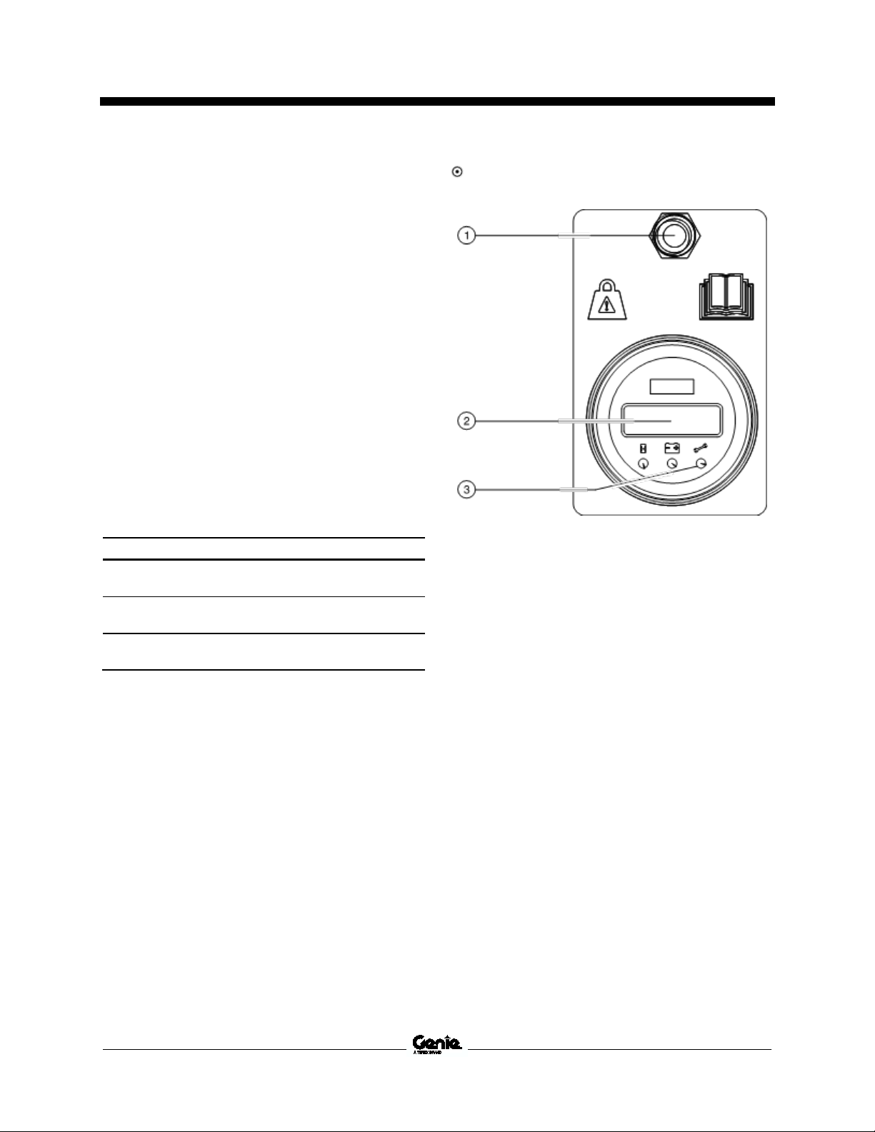
Service and Repair Manual August 2022
Model Maximum rated load
GS
bs
g
GS
bs
g
GS
bs
g
Platform Overload Components
Platfor m Ov er lo ad C omp one nt s
How to Cali brat e th e Pl atf orm Ove rload S yste m
How to Calibrate the Platform
Overload System
Machines with platform overload systems, proper
calibration is essential to safe machine operation.
An improperly calibrated platform overload system
could result in the system failing to sense an
overloaded platform. The stability of the machine
is compromised and it could tip over.
Note: Perform this procedure with the machine on
a firm, level surface with all weight, tools and
equipment removed from the platform.
Note: Perform this procedure in an area that is free
of overhead obstructions.
1 Models with outriggers: Fully lower the
outriggers and level the machine.
2 Using a suitable lifting device, place and
secure the maximum rated load in the center
of the platform deck.
-2669
-3369 1000 l
-4069
1500 l
680 k
454 k
800 l
363 k
Result: The red LED is on and the LCD
screen displays LOAD.
1 calibration toggle switch
2 LCD screen
3 red LED
3 Turn the key switch to ground control and pull
out the red Emergency Stop button to the on
position at the platform controls.
4 Pull out the red Emergency Stop button at the
ground controls and momentarily activate the
calibration toggle switch in the up position
3 times.
78 GS
™
-2669 DC • GS™-3369 DC • GS™-4069 DC Part No. 1306585GT
Page 91

August 2022 Service and Repair Manual
Model
Additional weight
GS
bs
g
GS
bs
91 kg
GS
bs
g
Platform Overload Components
5 Activate and hold the calibration toggle switch
in the up position for 4 seconds to enter full
load calibration mode.
Confirm Calibration:
1 Add additional weight to the platform.
Result: The LCD screen first displays DOWN
CHK, then GO UP: ?.
6 Start the engine from the ground controls and
fully raise the platform.
7 When the platform has reached full height,
momentarily activate the calibration toggle
switch in the up position to confirm.
Result: The LCD screen first displays UP
CHK, then GO DWN: ?.
8 Fully lower the platform to the stowed
position.
9 When the platform is fully stowed,
momentarily activate the calibration toggle
switch in the up position to confirm.
10 Fully raise the platform from the ground
controls.
Note: The platform will raise and automatically
stop at predetermined points to gather data.
Continue holding the Function Enable and
Platform Up buttons until the platform has reached
full height.
-2669 300 l
136 k
-3369
-4069 160 l
200 l
73 k
2 Pull out the red Emergency Stop button to the
on position and start the engine.
3 Raise the platform.
Result: At a predetermined height the engine
shuts off, an audible alarm sound and
platform up function does not operate.
4 Cycle the red Emergency Stop button off,
then back on.
5 Use the emergency down function to lower
the platform to the stowed position.
6 Remove the weight or rated load from the
platform.
11 When the platform has reached full height,
momentarily activate the calibration toggle
switch in the up position to confirm.
12 Fully lower the platform to the stowed
position.
Note: The platform will lower and automatically
stop at predetermined points to gather data.
Continue holding the Function Enable and
Platform Down buttons until the platform is fully
stowed.
13 When the platform is fully stowed,
momentarily activate the calibration toggle
switch in the up position to confirm.
Result: The LCD screen displays Success.
Calibration is complete.
14 Push in the ground controls red Emergency
Stop button to the off position.
Part No. 1306585GT GS
™
-2669 DC • GS™-3369 DC • GS™-4069 DC 79
Page 92

Service and Repair Manual August 2022
Platform Overload Components
11-2 Platfo rm Ov erlo ad R ecov e ry
11-2
Platform Overload Recovery
Message
If the ground controls LCD screen displays OL:
PLATFORM OVERLOADED, the emergency
lowering system has been used while the platform
was overloaded.
How to Clear the Platform
Overload Recovery Message
Note: This message shall be cleared by a person
trained and qualified on the troubleshooting and
repair of this machine.
Note: Use the following chart to identify the
description of each LCD screen control button
used in this procedure.
3 Pull out the red Emergency Stop button at the
ground controls.
Result: The ground control LCD display will
show the following.
4 Press the scroll down button.
Result: The ground control LCD display will
show the following.
5 Press the enter button.
Escape Scroll up Scroll down Enter
1 Turn the key switch to the ground controls
position and pull out the red Emergency Stop
button to the on position at the platform
controls.
2 Press and hold the ground control scroll up
and scroll down buttons.
Result: The ground control LCD display will
show the following.
6 Press the enter button.
Result: The ground control LCD display will
show the following.
80 GS
™
-2669 DC • GS™-3369 DC • GS™-4069 DC Part No. 1306585GT
Page 93

August 2022 Service and Repair Manual
Platform Overload Components
7 Press and hold the scroll down button for
5 seconds.
Result: The ground control LCD display will
show the following.
8 Press the enter button.
Result: The ground control LCD display will
show the following.
9 Press the buttons in the following sequence:
(down)(down)(up)(enter).
Note: After each key press an asterisk (*) will
appear on the second line of the LCD display.
Result: The ground control LCD display will
show the following.
Note: After 3 seconds the LCD display will return
to SELECT OPTION PLAT. OVERLOAD.
10 Push in the red Emergency stop button.
Part No. 1306585GT GS
™
-2669 DC • GS™-3369 DC • GS™-4069 DC 81
Page 94

Service and Repair Manual August 2022
Model
Measurement
GS
nches
163 - 193 cm
GS
nches
m
GS
nches
m
Platform Overload Components
11-3 Down Limit Height
11-3
Down Limit Height
How to Cali brat e th e Dow n Limit Heig ht
7 Connect the Tech Pro Link to the machine.
8 Turn the key switch to ground control and pull
out the red Emergency Stop button to the on
position at both ground and platform controls.
How to Calibrate the Down Limit
Height
Note: Perform this procedure on a firm, level
surface with the machine in the stowed position
unless otherwise instructed.
®
Note: The Genie
to adjust the platform down limit height.
1 Open the ground controls compartment and
locate the level sensor.
2 Start the engine from the ground controls.
3 Push and hold the level to the side until an
audible alarm is heard.
4 Raise the platform until it stops.
5 Push in the red Emergency Stop button to the
off position.
6 Measure the distance between the surface
and the platform floor.
-2669 64 - 76 i
Tech Pro™ Link will be required
9 Go to Settings / Calibration / DLS Percentage.
Increase or decrease the setting between
3.0% - 11%. Repeat this procedure until
platform up stops within the required range.
Note: The default setting is 9.0%.
-3369
-4069 74 - 86 i
Result: Platform height is within range.
Adjustment not required.
Result: Platform height is not within range.
Continue with procedure.
™
82 GS
-2669 DC • GS™-3369 DC • GS™-4069 DC Part No. 1306585GT
66 - 78 i
168 - 198 c
188 - 218 c
Page 95

August 2022 Service and Repair Manual
Crushing hazard.
or replacing any hydraulic
component, always support
the structure and secure it
from movement
Electrocution/burn hazard.
Contact with electrically charged
circuits could result in death or
serious injury. Remove all rings,
watches and othe
Bodily injury hazard. Spraying
hydraulic oil can penetrate and
burn skin. Loosen hydraulic
connections very slowly to allow
the oil pressure to dissipate
gradually. Do not allow oil to
squirt or spray.
Fault Codes
Section 4 Fault Codes
Introductio n
Before Troubleshooting:
Observe and Obey:
Troubleshooting and repair procedures shall
be completed by a person trained and
qualified on the repair of this machine
Immediately tag and remove from service a
damaged or malfunctioning machine.
Repair any machine damage or malfunction
before operating the machine.
Unless otherwise specified, perform each
procedure with the machine in the following
configuration:
• Machine parked on a firm, level surface
• Key switch in the off position with the key
removed
• The red Emergency Stop button in the off
position at both the ground and platform
controls
Read, understand and obey the safety rules
and operating instructions in the appropriate
operator's manual on your machine.
Be sure that all necessary tools and test
equipment are available and ready for use.
Read each appropriate fault code thoroughly.
Attempting short cuts may produce hazardous
conditions.
Be aware of the following hazards and follow
generally accepted safe workshop practices.
When testing
r jewelry.
• Wheels chocked
• All external AC power supply disconnected
from the machine
• Platform in the stowed position
Part No. 1306585GT GS
Indicates that a specific result is expected
after performing a series of steps.
Indicates that an incorrect result has occurred
after performing a series of steps.
™
-2669 DC • GS™-3369 DC • GS™-4069 DC 83
Page 96

Service and Repair Manual August 2022
Fault Codes
About This Section
When a malfunction is discovered, the fault code
charts in this section will help a service
professional pinpoint the cause of the problem.
To use this section, basic hand tools and certain
pieces of test equipment are required — voltmeter,
ohmmeter, pressure gauges.
Definitions
GSDS – Genie SmartLink™ Diagnostic System
ECM – Electronic Control Module
DCON - Drive Controller
GCON LCD Diagnostic Readout
The diagnostic readout displays alpha numeric
codes that provide information about the machine
operating status and about malfunctions.
The codes listed in the Diagnostic Trouble Code
Charts describe malfunctions and can aid in
troubleshooting the machine by pinpointing the
area or component affected.
GCON – Ground Controls
PCON – Platform Controls
OIC – Operational Indicator Codes
DTC – Diagnostic Trouble Codes
Models are listed below each code to assist in the
troubleshooting codes for a specific model.
84 GS
™
-2669 DC • GS™-3369 DC • GS™-4069 DC Part No. 1306585GT
Page 97

August 2022 Service and Repair Manual
Fault Codes
Genie® SmartLink™ Diagnostic
System
This machine is equipped with the Genie
SmartLink™ Diagnostic System (GSDS). The
GSDS indicates a machine malfunction has
happened by displaying Operational Indicator
Codes (OIC) and Diagnostic Trouble Codes
(DTC). These codes are displayed at the Platform
Controls and the Ground Controls. The Ground
Controls will display a brief description of the code
at the LCD display as well. Refer to the GCON I/O
Maps, Operational Indicator Codes (OIC) and
Diagnostic Trouble Codes (DTC) in this section, to
assist in troubleshooting faults.
GCON ECM Connector Layout
Rear of Ground Controls ECM (models without
outriggers)
Part No. 1306585GT GS
Rear of Ground Controls ECM (models with outriggers)
™
-2669 DC • GS™-3369 DC • GS™-4069 DC 85
Page 98

Service and Repair Manual August 2022
Fault Codes
GCON I/O Map
GCON I/O MAP
Ground Controls
Pin Number
C1-01 ECM / Logic Power Power Input RD
C1-02 PCON - E-Stop Power Power Output WH
C1-03 PCON - E-Stop Return Power Input BK
C1-04 Link to PCON - CAN HI Data Bus YL
C1-05 Link to PCON - CAN LOW Data Bus GR
C1-06 PCON - Ground Ground Output BR
C1-07 GCON - Ground Ground Output BR
C1-08 Key Switch - PCON Mode Digital Input BK
C1-09 Key Switch - GCON Mode Digital Input WH
C1-10 GCON - Emer gency Stop Digital Input RD
C1-11 Accumulator Pressure Sw itch Digital Input OR/RD
C1-12 ECM Driver Power Power Input RD
C2-01 Platform Up Coil Digital Output OR
C2-02 Platform Down Coil Digital Output OR/BK
C2-03 Steer Left Coil Digital Output BL/BK
C2-04 Steer Right Coil Digital Output BL
C2-05 Oscillate Supply C oil Digital Output GR/WH
C2-06 Oscillate Right Coil Digital Output GR/BK
C2-07 Not used
C2-08 Brake Relay CR60 Digital Output WH/RD
C2-09 Oscillate Left Digital Output GR
C2-10 Accumulator Coil Digital Output OR/RD
C2-11 Not used
C2-12 Not used
Circuit Function I/O Type Wire Color
C1 Connector - Gray
C2 Connector - Black
86 GS
™
-2669 DC • GS™-3369 DC • GS™-4069 DC Part No. 1306585GT
Page 99

August 2022 Service and Repair Manual
Fault Codes
Ground Controls
Pin Number
C3-01 Not used
C3-02 GCON - Alarm Digital Output WH/RD
C3-03 Sensor Power Digital Output RD
C3-04 Automotive Horn Digital Output WH
C3-05 Left Oscillate Limit Switc h Digital Input GR/BK
C3-06 Right Oscillate Limit Switch Digital Input GR
C3-07 Down Limit Switch - LS6 Digital Input OR
C3-08 Digital Level Sensor (if equipped) Digital Input RD/BK
C3-09 Platform Overload Pressure Switch (platform overload option) Digital Input BL
C3-10 Platform Overload Pressure Switch (platform overload option) Digital Input WH/BK
C3-11 Pump Speed Hz Digital Input OR/BK
C3-12 Sensor Ground Digital Input BK
C4-01 Left Front Outrigger Limit Switch Digital Input BK
C4-02 Right Front Outrigger Limit Sw itch Digital Input OR
C4-03 Left Rear Outrigger Limit Switch Digital Input BL
C4-04 Right Rear Outrigger Limit Switch Digital Input GR
C4-05 Level Sensor X Axis Analog Input GR/WH
C4-06 Level Sensor Y Axis Analog Input GR/BK
C4-07 Left Front Outrigger Coil Digital Output BK/WH
C4-08 Right Front Outrigger Coil Digital Output OR/WH
C4-09 Left Rear Outrigger Coil Digital Output BL/WH
C4-10 Right Rear Outrigger Coil Digital Output GR/WH
C4-11 Outrigger Extend C oil Digital Output WH/RD
C4-12 Outrigger Retract Coil Digital Output WH/BK
Circuit Function I/O Type Wire Color
C3 Connector - Green
C4 Connector - Brown (Outrigger O ption)
GCON I/O MAP
Part No. 1306585GT GS
™
-2669 DC • GS™-3369 DC • GS™-4069 DC 87
Page 100

Service and Repair Manual August 2022
Platform Overload Fault Codes
Platfor m Ov er lo ad Fa ul t C od e s
Platform Overload Display
1 LCD screen
2 red LED
The diagnostic readout displays numerical codes that provide information about height sensor, pressure
sensor and platform overload malfunctions.
The codes listed in the Fault Code Chart can aid in troubleshooting the machine by pinpointing the area or
component affected.
88 GS
™
-2669 DC • GS™-3369 DC • GS™-4069 DC Part No. 1306585GT
 Loading...