


Operator's Manual
Serial Number Range
IWP® Super
Series
from IWPP-13000
ANSI/CSA
North America
South America
Asia
with
Maintenance
Information
Original Instructions
Sixth Edition
First Printing
Part No. 1298036GT

Operator's Manual Sixth Edition • First Printing
IWP® Super Series Part No. 1298036GT
Front Matter
Contents
Introduction ............................................................1
Symbol and Hazard Pictorials Definitions ..............5
General Safety .......................................................7
Personal Safety ................................................... 11
Work Area Safety ................................................ 12
Legend ................................................................ 18
Controls ............................................................... 19
Inspections .......................................................... 20
Operating Instructions ......................................... 32
Maintenance ....................................................... 35
Battery Charging Instructions ............................. 37
Transport and Lifting Instructions ....................... 39
Specifications ...................................................... 41
Copyright © 1996 Terex Corporation
Sixth Edition: First Printing, March 2020
"Genie" and "IWP" are registered trademarks of Terex South
Dakota in the U.S.A. and many other countries.
"Super Series" is a trademark of Terex South Dakota.
These machines comply with
ANSI/SAIA A92.20
CAN/CSA B354.6

Sixth Edition • First Printing Operator's Manual
Introduction
Part No. 1298036GT IWP® Super Series 1
Introduction
About this manual
Genie appreciates your choice of our machine for
your application. Our number one priority is user
safety, which is best achieved by our joint efforts.
This book is an operation and daily maintenance
manual for the user or operator of a Genie
machine.
This manual should be considered a permanent
part of your machine and should remain with the
machine at all times. If you have any questions,
contact Genie.
Product Identification
The machine serial number is located on the serial
label.
Serial number stamped
on chassis
Serial label
Intended Use and Familiarization
Guide
The intended use of this machine is to lift
personnel, including tools, and materials to an
aerial work site. Before operating the machine, it’s
the operator’s responsibility to read and
understand this familiarization guide.
Each person must be trained to operate a
Mobile Elevating Work Platform (MEWP).
Familiarization with the MEWP must be given
to each person who is authorized, competent
and trained.
Only trained and authorized personnel should
be permitted to operate the machine.
The operator is responsible to read,
understand, and obey the manufacturer’s
instructions and safety rules provided in the
Operator’s Manual.
The Operator’s Manual is located in the
manual storage container, at the platform.
For specific product applications, see
Contacting The Manufacturer.
Operator's Manual Sixth Edition • First Printing
Introduction
2 IWP® Super Series Part No. 1298036GT
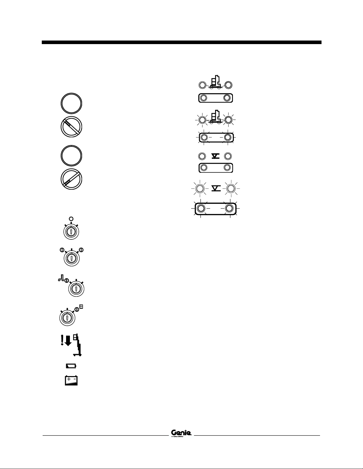
Platform controls symbology and related
machine movement:
Platform up
Platform down
Ground controls symbology and related
machine movement:
Keyswitch - Off
Keyswitch - On
Ground controls
Platform controls
Emergency platform
lowering
Low battery indicator
Footpad interlock - Off
Footpad interlock - On
Level sensor interlock - Off
Level sensor interlock - On
Interlocked functions:
All platform and ground controls.
Limitations of use:
The intended use of this machine is to lift
personnel, including tools, and materials to an
aerial work site.
Do not elevate the platform unless the machine
is on firm level ground.

Sixth Edition • First Printing Operator's Manual
Introduction
Part No. 1298036GT IWP® Super Series 3
Bulletin Distribution and
Compliance
Safety of product users is of paramount
importance to Genie. Various bulletins are used by
Genie to communicate important safety and
product information to dealers and machine
owners.
The information contained in the bulletins is tied to
specific machines using the machine model and
serial number.
Distribution of bulletins is based on the most
current owner on record along with their
associated dealer, so it is important to register
your machine and keep your contact information
up to date.
To ensure safety of personnel and the reliable
continued operation of your machine, be sure to
comply with the action indicated in a respective
bulletin.
To view any open bulletins for your machine, visit
us on the web at www.genielift.com.
Contacting the Manufacturer
At times it may be necessary to contact Genie.
When you do, be ready to supply the model
number and serial number of your machine, along
with your name and contact information. At
minimum, Genie should be contacted for:
Accident reporting
Questions regarding product applications and
safety
Standards and regulatory compliance information
Current owner updates, such as changes in
machine ownership or changes in your contact
information. See Transfer of Ownership, below.
Transfer of Machine Ownership
Taking a few minutes to update owner information
will ensure that you receive important safety,
maintenance and operating information that
applies to your machine.
Please register your machine by visiting us on the
web at www.genielift.com or by calling us toll free
at 1-800-536-1800.

Operator's Manual Sixth Edition • First Printing
Introduction
4 IWP® Super Series Part No. 1298036GT
Danger
Failure to obey the instructions and
safety rules in this manual will result
in death or serious injury.
Do Not Operate Unless:
You learn and practice the principles of safe
machine operation contained in this operator’s
manual.
1 Avoid hazardous situations.
Know and understand the safety rules
before going on to the next section.
2 Always perform a pre-operation inspection.
3 Always perform function tests prior to use.
4 Inspect the workplace.
5 Only use the machine as it was intended.
You read, understand and obey the
manufacturer’s instructions and safety rules—
safety and operator’s manuals and machine
decals.
You read, understand and obey employer’s
safety rules and worksite regulations.
You read, understand and obey all applicable
governmental regulations.
You are properly trained to safely operate the
machine.
Safety Sign Maintenance
Replace any missing or damaged safety signs.
Keep operator safety in mind at all times. Use mild
soap and water to clean safety signs. Do not use
solvent-based cleaners because they may
damage the safety sign material.
Hazard Classification
Decals on this machine use symbols, color coding,
and signal words to identify the following:
Safety alert symbol—used to alert
you to potential personal injury
hazards. Obey all safety
messages that follow this symbol
to avoid possible injury or death.
Indicates a hazardous situation
which, if not avoided, will result in
death or serious injury.
Indicates a hazardous situation
which, if not avoided, could result
in death or serious injury.
Indicates a hazardous situation
which, if not avoided, could result
in minor or moderate injury.
Indicates a property damage
message.

Sixth Edition • First Printing Operator's Manual
Symbol and Hazard Pictorials Definitions
Part No. 1298036GT IWP® Super Series 5
Symbol and Hazard Pictorials Definitions
Read the operator’s
manual
Read the service
manual
Crush hazard
No smoking
Collision hazard
Crush hazard
Tip-over hazard
Tip-over hazard
Electrocution hazard
Tip-over hazard
Maintain required
clearance
Tip-over hazard
Use common sense
and planning to
control the movement
of the machine on or
near inclines.
Collision hazard
Tiedown
Burn hazard
Explosion hazard
Fire hazard
Electrocution hazard
Transport diagram

Operator's Manual Sixth Edition • First Printing
Symbol and Hazard Pictorials Definitions
6 IWP® Super Series Part No. 1298036GT
Voltage rating for
power to platform
Pressure rating for air
line to platform
Lifting point
Release brakes
Grounded AC
3-wire only
Replace damaged
wires and cords
Wheel load
Lanyard anchorage
points
Side force
Manual force
Footpad load
Indoor
Maximum capacity
Emergency lowering
Wind speed
Maximum capacity including occupant, tools,
materials and options

Sixth Edition • First Printing Operator's Manual
General Safety
Part No. 1298036GT IWP® Super Series 7
General Safety

Operator's Manual Sixth Edition • First Printing
General Safety
8 IWP® Super Series Part No. 1298036GT

Sixth Edition • First Printing Operator's Manual
General Safety
Part No. 1298036GT IWP® Super Series 9
Operator's Manual Sixth Edition • First Printing
General Safety
10 IWP® Super Series Part No. 1298036GT

Sixth Edition • First Printing Operator's Manual
Personal Safety
Part No. 1298036GT IWP® Super Series 11
Personal Safety
Personal Fall Protection
Personal fall protection equipment (PFPE) is not
required when operating this machine. If PFPE is
required by job site or employer rules, the
following shall apply:
All PFPE must comply with applicable
governmental regulations and must be inspected
and used in accordance with the manufacturer’s
instructions.

Operator's Manual Sixth Edition • First Printing
Work Area Safety
12 IWP® Super Series Part No. 1298036GT
Work Area Safety
Tip-over Hazards
Do not raise the platform unless the machine is on
a firm, level surface.
Do not move the machine while the platform is
raised.
Do not cause a horizontal force or side load to
machine by raising or lowering a fixed or
overhanging load.
Do not transport tools and materials unless they
are evenly distributed and can be safely handled
by the person in the platform.
Do not place or attach fixed or overhanging loads
to any part of this machine.
Do not place ladders or scaffolds in the platform or
against any part of this machine.
Do not push off or pull toward any object outside of
the platform.
Maximum allowable manual force
45 lbs / 200 N
Do not operate the machine near drop-offs, holes,
bumps, debris, unstable or slippery surfaces or
other possible hazardous conditions.
Do not alter or disable machine components that
in any way affect safety and stability.
Do not replace items critical to machine stability
with items of different weight or specification.
Do not tie the platform to adjacent structures.
Do not place loads outside the platform perimeter.
Use only Genie approved replacement parts.
When moving the machine with a forklift or other
transport vehicle, the platform should be fully
lowered, the machine should be turned off and no
personnel shall remain in the platform.
Do not use the machine on a moving or mobile
surface or vehicle.
Do not alter or modify a mobile elevating work
platform without prior written permission from the
manufacturer. Mounting attachments for holding
tools or other materials onto the platform,
toeboards, or guard rail system can increase the
weight in the platform and the surface area of the
platform or the load.

Sixth Edition • First Printing Operator's Manual
Work Area Safety
Part No. 1298036GT IWP® Super Series 13
Do not operate the
machine in strong or gusty
winds. Do not increase the
surface area of the
platform or the load.
Increasing the area
exposed to the wind will
decrease machine
stability.
Occupants, equipment
and materials shall not
exceed the maximum
platform capacity.
ANSI, CSA, AUS & CE models
Maximum capacity
350 lbs
159 kg
Maximum occupants
1 person
ANSI, AUS & CE models
Maximum capacity
IWP-20S with outreach
option
300 lbs
136 kg
Maximum occupants
1 person
Do not install the outreach option on an IWP-25S
or an IWP-30S. The outreach option is for the
IWP-20S.
Fall Hazards
The guard rail system provides fall protection. If
occupant(s) of the platform are required to wear
personal fall protection equipment (PFPE) due to
job site or employer rules, PFPE and its use shall
be in accordance with the PFPE manufacturer’s
instructions and applicable governmental
requirements. Attach the lanyard to the anchor
provided in the platform.
Do not sit, stand, or climb
on the platform guard
rails. Maintain a firm
footing on the platform
floor at all times.
Do not exit the platform while raised. If a power
failure occurs, have ground personnel activate the
manual lowering valve.
Keep the platform floor clear of debris.
Lower the platform entry mid-rail or gate before
operating.

Operator's Manual Sixth Edition • First Printing
Work Area Safety
14 IWP® Super Series Part No. 1298036GT
Electrocution Hazards
This machine, even with an optional fiberglass
platform, is not electrically insulated and will not
provide protection from contact with or proximity to
electrical current.
Keep away from the machine if it contacts
energized power lines or becomes electrically
charged. Personnel on the ground or in the
platform must not touch or operate the machine
until energized power lines are shut off.
Obey all local and governmental regulations
regarding required clearance from electrical power
lines. At a minimum, the required clearance
contained in the chart below must be followed.
Voltage
Phase to Phase
Minimum Safe
Approach Distance
0 to 300V
Avoid Contact
300V to 50KV
10 ft
3.05 m
50KV to 200KV
15 ft
4.60 m
200KV to 350KV
20 ft
6.10 m
350KV to 500KV
25 ft
7.62 m
500KV to 750KV
35 ft
10.67 m
750KV to 1000KV
45 ft
13.72 m
Allow for platform movement, electrical line sway
or sag, and beware of strong or gusty winds.
Do not use the machine as a ground for welding.
Do not operate an AC powered machine or a DC
battery charger unless using a 3-wire grounded
extension cord connected to a grounded AC
circuit. Do not alter or disable 3-wire grounded
plugs.
Collision Hazards
Operators must comply with employer, job site,
and governmental rules regarding use of personal
protective equipment.
Check the work area for overhead obstructions or
other possible hazards.
Be aware of crushing hazards when grasping the
platform guard rail.
Do not lower the platform unless the area below is
clear of personnel and obstructions.

Sixth Edition • First Printing Operator's Manual
Work Area Safety
Part No. 1298036GT IWP® Super Series 15
Use common sense and
planning to control the
movement of the
machine on or near
inclines.
Stay clear of descending platform.
Damaged Machine Hazards
Do not use a damaged or malfunctioning machine.
Be sure all maintenance has been performed as
specified in this manual and the appropriate Genie
service manual.
Be sure all decals are in place and legible.
Be sure the operator's, safety and responsibilities
manuals are complete, legible and in the storage
container located on the platform.
Conduct a thorough pre-operation inspection of
the machine and test all functions before each
work shift. Immediately tag and remove from
service a damaged or malfunctioning machine.
Do not use the machine as a ground for welding.
Improper Use Hazard
Do not leave the machine unattended unless the
key is removed to secure from unauthorized use.
Bodily Injury Hazard
Do not operate the machine with a hydraulic oil or
air leak. An air leak or hydraulic leak can penetrate
and/or burn skin.
Crushing Hazard
Keep hands and limbs out of mast.
Use common sense and planning when operating
the machine with the controller from the ground.
Maintain safe distances between the operator, the
machine and fixed objects.
Explosion and Fire Hazards
Do not operate the machine or charge the battery
in hazardous locations or locations where
potentially flammable or explosive gases or
particles may be present.

Operator's Manual Sixth Edition • First Printing
Work Area Safety
16 IWP® Super Series Part No. 1298036GT
Outreach Option Safety
Bodily Injury Hazard
Keep hands and feet away from moving parts:
mounting plate, locking bracket and extension
arms.
Power Wheel Assist Option
Safety
Collision Hazard
Limit travel speed according to the condition of the
ground surface, congestion, slope, location of
personnel, and any other factors which may cause
collision.
Be aware of limited sight distance when moving
the machine.
Do not move the machine with the platform raised.
When moving the machine on an incline, operate
from the uphill side of the machine.
Do not rely on the brake to hold the machine on an
incline.
Battery Safety
Burn Hazards
Batteries contain acid.
Always wear protective
clothing and eye wear when
working with batteries.
Avoid spilling or contacting
battery acid. Neutralize
battery acid spills with
baking soda and water.
The battery pack must
remain in the upright
position.
Do not expose the batteries or the charger to
water or rain during charging.

Sixth Edition • First Printing Operator's Manual
Work Area Safety
Part No. 1298036GT IWP® Super Series 17
Explosion Hazards
Keep sparks, flames, and
lighted tobacco away from
batteries. Batteries emit
explosive gas.
Charge the battery in a well
ventilated area.
Do not contact the battery
terminals or the cable
clamps with tools that may
cause sparks.
Do not disconnect charger
DC output wires from the
battery when the charger is
on.
Component Damage Hazard
Do not use any battery charger greater than 24V
to charge the batteries.
Electrocution/Burn Hazards
Connect the battery charger to a
grounded, AC 3-wire electrical
outlet only.
Inspect daily for damaged cords,
cables and wires. Replace
damaged items before operating.
Avoid electrical shock from contact with battery
terminals. Remove all rings, watches and other
jewelry.
Hazard
The battery pack weighs 90 lbs / 40.8 kg. Use the
appropriate number of people and proper lifting
techniques when lifting the battery pack.
Use the appropriate number of people and proper
lifting techniques when lifting batteries.
Lockout After Each Use
1 Select a safe parking location—firm level
surface, clear of obstruction and traffic.
2 Lower the platform.
3 Turn the key switch to the off position and
remove the key to secure from unauthorized
use.
4 Charge the batteries.

Operator's Manual Sixth Edition • First Printing
Legend
18 IWP® Super Series Part No. 1298036GT
Legend
1 AC models: Power supply for
machine
DC models: Power to
platform
2 Ground controls
3 Circuit breaker
4 Mast
5 Platform
6 Lanyard anchorage point
7 Operator's manual storage
container
8 Lifting eye
9 Breather cap
10 Platform controls
11 Level sensor with bubble
level*
12 AC outlet
13 DC models: Battery quick
disconnect
14 DC models: Battery pack
15 Footpad
16 Transport tie-down
17 Platform entry mid-rail or gate
18 Forklift ring
19 Left side leveling jack
20 Winching point
21 Counterweight
22 Right side leveling jack
23 Forklift pocket
24 DC models: Battery charger
25 Level sensor with bubble
level*
26 Foot pedal
27 Power wheel assist option
28 Manual lowering valve
(located at the bottom of the
hydraulic cylinder)
29 Battery strap
30 Steer handle - power wheel
assist option
31 Base lowering handle
32 Function enable lever - power
wheel assist option
33 Steering handle
34 Direction-reversing safety
switch - power wheel assist
option
35 Thumb rocker switch - power
wheel assist option
*Two different styles of level sensor
were produced.

Sixth Edition • First Printing Operator's Manual
Controls
Part No. 1298036GT IWP® Super Series 19
Controls
Ground controls
The ground control station can be used in
the event of an emergency to rescue an
incapacitated person in the platform.
Note: Two different interlock display
decals were produced. The symbols
on them are different but they both
operate the same way. Both are
illustrated here and in the text
throughout this manual.
Platform controls
1 DC models: Low battery indicator light
2 Low battery indicator light for auxiliary lowering
3 Power light
4 Auxiliary platform lowering button
5 Red Emergency Stop button
6 Key switch
7 Level sensor interlock display lights
8 Footpad interlock display lights
9 Control activate button
10 Up/Down switch

Operator's Manual Sixth Edition • First Printing
Inspections
20 IWP® Super Series Part No. 1298036GT
Inspections
Do Not Operate Unless:
You learn and practice the principles of safe
machine operation contained in this operator’s
manual.
1 Avoid hazardous situations.
2 Always perform a pre-operation
inspection.
Know and understand the pre-operation
inspection before going on to the next
section.
3 Always perform function tests prior to use.
4 Inspect the workplace.
5 Only use the machine as it was intended.
Pre-operation Inspection
Fundamentals
It is the responsibility of the operator to perform a
pre-operation inspection and routine maintenance.
The pre-operation inspection is a visual inspection
performed by the operator prior to each work shift.
The inspection is designed to discover if anything
is apparently wrong with a machine before the
operator performs the function tests.
The pre-operation inspection also serves to
determine if routine maintenance procedures are
required. Only routine maintenance items specified
in this manual may be performed by the operator.
Refer to the list on the next page and check each
of the items.
If damage or any unauthorized variation from
factory delivered condition is discovered, the
machine must be tagged and removed from
service.
Repairs to the machine may only be made by a
qualified service technician, according to the
manufacturer’s specifications. After repairs are
completed, the operator must perform a preoperation inspection again before going on to the
function tests.
Scheduled maintenance inspections shall be
performed by qualified service technicians,
according to the manufacturer’s specifications and
the requirements listed in the responsibilities
manual.

Sixth Edition • First Printing Operator's Manual
Inspections
Part No. 1298036GT IWP® Super Series 21
Pre-operation Inspection
Be sure that the operator’s, safety and
responsibilities manuals are complete, legible
and in the storage container located in the
platform.
Be sure that all decals are legible and in place.
See Decals section.
Check for hydraulic oil leaks and proper oil
level. Add oil if needed. See Maintenance
section.
DC models: Check for battery fluid leaks and
proper fluid level. Add distilled water if needed.
See Maintenance section.
Check the following components or areas for
damage, improperly installed, or missing parts and
unauthorized modifications:
Electrical components, wiring, and
electrical cables
Hydraulic power unit, hoses, fittings and
cylinders
Hydraulic manifolds and foot pump
Platform entry mid-rail or gate
Sequencing cables and pulleys
Lifting chains and idler wheels
Mast columns and counterweight
Nuts, bolts and other fasteners
Breather cap
Foot pads
Adjustable glide pads
Lanyard anchorage points
Casters
If equipped: Power wheel assist option
Steer handle
Hydraulic motor and hoses
If equipped: IWP-20S with Outreach option
Locking bracket
Handle and handle lock
Extension arms
Confirm proper counterweight
configuration (part number is stamped on
top of counterweight)
ANSI & CE Indoor
Front P/N
Rear P/N
IWP-20S Standard Base
37354
37355
Check entire machine for:
Cracks in welds or structural components
Dents or damage to machine
Excessive rust, corrosion or oxidation
Inspect and clean battery terminals and all
battery cable connections.
Verify that all structural and other critical
components are present and all associated
fasteners and pins are in place and properly
tightened.

Operator's Manual Sixth Edition • First Printing
Inspections
22 IWP® Super Series Part No. 1298036GT
Do Not Operate Unless:
You learn and practice the principles of safe
machine operation contained in this operator’s
manual.
1 Avoid hazardous situations.
2 Always perform a pre-operation inspection.
3 Always perform function tests prior to
use.
Know and understand the function tests
before going on to the next section.
4 Inspect the workplace.
5 Only use the machine as it was intended.
Function Test Fundamentals
The function tests are designed to discover any
malfunctions before the machine is put into
service. The operator must follow the step-by-step
instructions to test all machine functions.
A malfunctioning machine must never be used. If
malfunctions are discovered, the machine must be
tagged and removed from service. Repairs to the
machine may only be made by a qualified service
technician, according to the manufacturer’s
specifications.
After repairs are completed, the operator must
perform a pre-operation inspection and function
tests again before putting the machine into
service.

Sixth Edition • First Printing Operator's Manual
Inspections
Part No. 1298036GT IWP® Super Series 23
Function Tests
Setup
1 Select a test area that is firm, level and free of
hazards.
2 Pump the foot pedal
to raise the base.
Result: The wheels
should contact the
ground.
3 Pull the base lowering
handle to fully lower
the base.
Result: All four foot
pads should come in
firm contact with the
ground.
4 Connect to the appropriate power source.
5 Use the bubble level and adjust the leveling
jacks until the machine is level and all four foot
pads are in firm contact with the ground.
6 Insert the key and turn to platform control.
7 Pull out the red Emergency Stop button at the
ground controls to the on position.
8 Pull out the platform red Emergency Stop
button to the on position.
Result: The power light should come on.
Within 1 to 4 seconds, the two level sensor
interlock display lights and the two foot pad
interlock display lights should turn on and
remain on.
Note: Two different interlock display decals were
produced. The symbols on them are different but
they both operate the same way. Both are
illustrated here and in the text throughout this
manual.
Test Interlock System
9 Pump the foot pedal to raise the base.
Result: The two footpad display lights should
be off.

Operator's Manual Sixth Edition • First Printing
Inspections
24 IWP® Super Series Part No. 1298036GT
10 Pull the base lowering handle to fully lower the
base.
Result: The two footpad display lights should
be on.
11 Pump the foot pedal to raise the base.
12 Turn both the leveling jacks clockwise to the
full down position.
13 Pull the base lowering handle to fully lower the
base.
Result: The base will lower and the two level
sensor display lights should be off and remain
off because the base is not level.
14 At the platform controls, push in the control
activate button and rotate the up/down switch
to the up position, then the down position.
Result: The platform up/down function should
not operate.
Test Emergency Stop
15 Use the bubble level and adjust the leveling
jacks until the machine base is level. Be sure
all four display lights at the ground controls are
on.
16 Push in the ground red Emergency Stop
button to the off position.
17 Push in the control activate button and rotate
the up/down switch in the direction of intended
travel.
Result: The up/down function should not
operate.
18 Push in the platform red Emergency Stop
button to the off position.
19 Pull out the red Emergency Stop button at the
ground controls to the on position.
20 Push in the control activate button and rotate
the up/down switch in the direction of intended
travel.
Result: The up/down function should not
operate.

Sixth Edition • First Printing Operator's Manual
Inspections
Part No. 1298036GT IWP® Super Series 25
Test Auxiliary Platform Lowering
21 Raise the platform slightly.
Result: The inner frame wheels should lift off
the ground.
22 Disconnect the power source from the
machine.
23 Turn the key switch to ground control.
24 Push in the auxiliary platform lowering button
at the ground controls.
Result: The platform should lower.
25 Connect the power source to the machine.
26 Turn the key switch to platform control.
27 Raise the platform slightly.
28 Disconnect the power source from the
machine.
29 Push in the control activate button and rotate
the up/down switch in the down direction.
Result: The platform should lower.
30 Connect the power source to the machine.
Test Manual Lowering
31 Pull out the red Emergency Stop button at the
platform controls to the on position. Confirm
that the interlock display lights and the power
light are on.
32 Push in the control activate button and rotate
the up/down switch to the up position to raise
the platform approximately 6 inches / 15 cm.
33 Activate the
manual lowering
valve located at
the bottom of the
hydraulic
cylinder.
Result: The platform should lower.
Test Platform Raise and Lower
34 Push in the control activate button and rotate
the up/down switch to the up position.
Result: The platform should raise smoothly,
free of hesitation.
35 Push in the control activate button and rotate
the up/down switch to the down position.
Result: The platform should lower.
Test the Direction-reversing Safety Switch
(models with Power Wheel Assist Option
only)
36 Pull and hold the function enable lever on
either side.
37 Press the thumb rocker switch and drive the
machine in the reverse direction.
38 Press the direction-reversing safety switch on
the end of the steer handle.
Result: The machine should travel in the
forward direction.

Operator's Manual Sixth Edition • First Printing
Inspections
26 IWP® Super Series Part No. 1298036GT
Do Not Operate Unless:
You learn and practice the principles of safe
machine operation contained in this operator’s
manual.
1 Avoid hazardous situations.
2 Always perform a pre-operation inspection.
3 Always perform function tests prior to use.
4 Inspect the workplace.
Know and understand the workplace
inspection before going on to the next
section.
5 Only use the machine as it was intended.

Sixth Edition • First Printing Operator's Manual
Inspections
Part No. 1298036GT IWP® Super Series 27
Workplace Inspection
Fundamentals
The workplace inspection helps the operator
determine if the workplace is suitable for safe
machine operation. It should be performed by the
operator prior to moving the machine to the
workplace.
It is the operator’s responsibility to read and
remember the workplace hazards, then watch for
and avoid them while moving, setting up, and
operating the machine.
Workplace Inspection Checklist
Be aware of and avoid the following hazardous
situations:
drop-offs or holes
bumps, floor obstructions, or debris
sloped surfaces
unstable or slippery surfaces
overhead obstructions and high voltage
conductors
hazardous locations
inadequate surface support to withstand all
load forces imposed by the machine
wind and weather conditions
the presence of unauthorized personnel
other possible unsafe conditions

Operator's Manual Sixth Edition • First Printing
Inspections
28 IWP® Super Series Part No. 1298036GT
Inspection for Decals with Words
Determine whether the decals on your machine
have words or symbols. Use the appropriate
inspection to verify that all decals are legible and
in place.
Part No. Decal Description
Qty
27857 Caution - Pipe Plug
1
28174 Label – Power to Platform, 230V*
2
28235 Label – Power to Platform, 115V*
2
28372 Label – Disconnect Battery Pack Plug
1
31070 Danger - Tip-over Hazard, Moving
1
31071 Warning - Failure to Read
1
31075 Caution - Crushing Hazard
4
31245 Warning - Collision Hazard
1
38116 Danger - Outreach Option Safety and
Instructions*
1
38117 Notice - Power Wheel Assist Option
Operating Instructions*
1
38119 Notice - Operating Instructions
1
38122 Label - Manual Storage Container
1
38149 Label – Patent
1
43657 Danger - Tip-over Hazard, Outreach
Option
1
48645 Danger - Power Wheel Assist Option
Safety*
1
52475 Label – Transport Tie-down
3
72086 Label – Lifting Point
1
72844 Danger - General Safety
1
82366 Label – Chevron Rando*
1
82802 Label - Function Enable
1
82907 Danger - Battery Charger Safety
1
82915 Label - Manual Lowering Valve
1
82986 Danger - Electrocution Hazard
1
97775 Label - Interlock Display
1
97815 Label – Lower Mid-rail
1
133046 Label – Input Power, 220V*
1
133496 Label - Wheel Load
2
133497 Label - Footpad Load
4
1272242 Label – Machine Registration/Owner
Transfer
1
1280819 Label – Warning, Prop 65
1
Part No. Decal Description
Qty
1281175 Label – Lanyard Anchorage Point, Fall
Restrained
1
1294398 Label – ANSI/CSA Compliant
1
1294685 Instructions – Annual Inspection
1
1298492 Label – Input Power, 100VAC*
1
1298945 Decal - Warning, Platform Locate
Light, Word*
1
1299004 Label – Transport Diagram
1
1299005 Notice – Max. Capacity/Side Force,
350 lbs, IWP*
1
1299006 Notice – Max. Capacity/Side Force,
300 lbs, IWP*
1
Shading indicates decal is hidden from
view, i.e. under covers* These decals are model,
option or configuration specific.

Sixth Edition • First Printing Operator's Manual
Inspections
Part No. 1298036GT IWP® Super Series 29

Operator's Manual Sixth Edition • First Printing
Inspections
30 IWP® Super Series Part No. 1298036GT
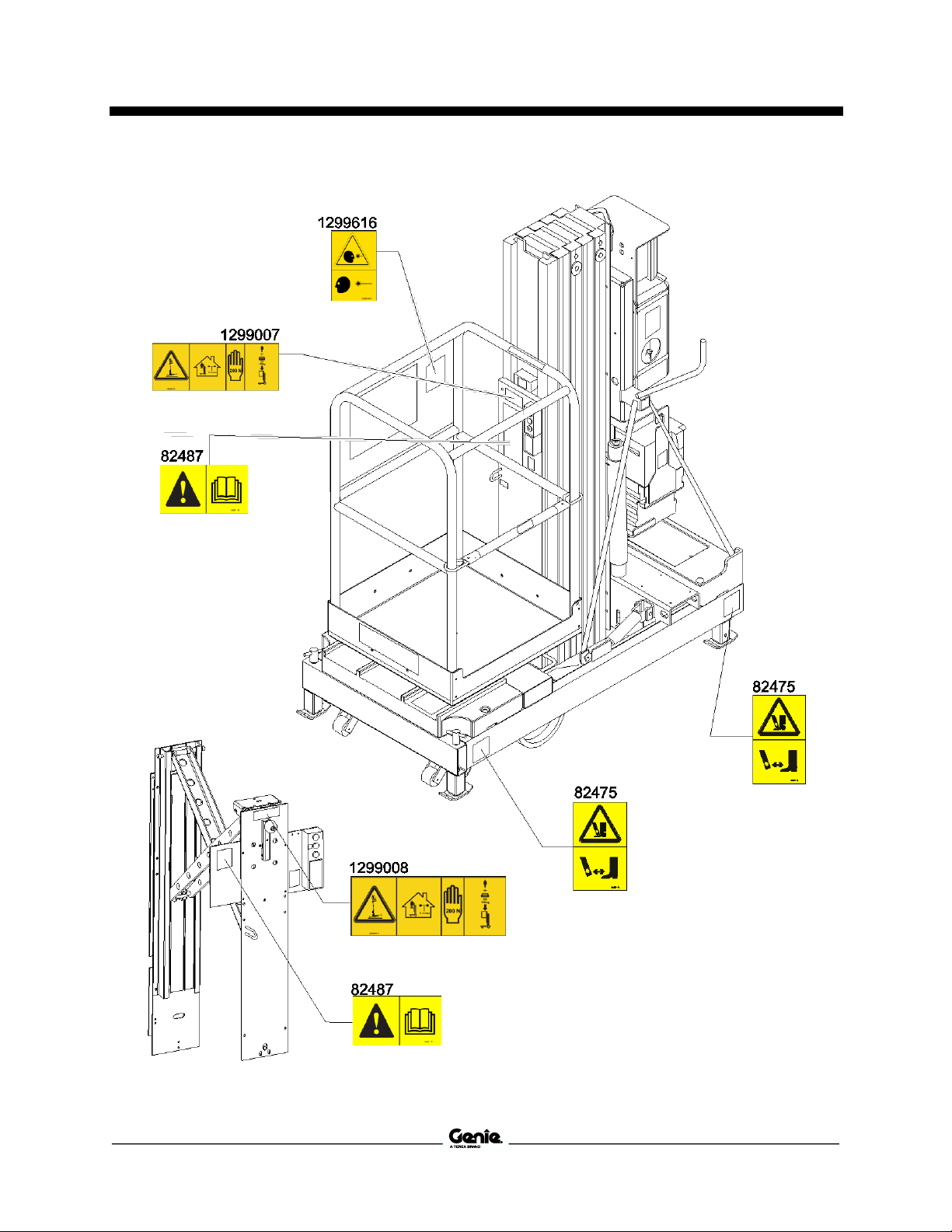
Inspection for Decals with
Symbols
Determine whether the decals on your machine
have words or symbols. Use the appropriate
inspection to verify that all decals are legible and
in place.
Part No. Decal Description
Qty
28174 Label – Power to Platform, 230V*
2
28235 Label – Power to Platform, 115V*
2
52475 Label – Transport Tie-down
3
72086 Label – Lifting Point
1
82366 Label – Chevron Rando*
1
82475 Label – Crushing Hazard, Outriggers
4
82481 Label – Battery/Charger Safety
1
82487 Label – Read the Manual
1
82802 Label - Function Enable
1
82915 Label - Manual Lowering Valve
1
82974 Warning - Collision Hazard
1
82987 Danger - Electrocution Hazard
1
97538 Label - Function Enable, Power
Wheel Assist
1
97775 Label - Interlock Display
1
97815 Label – Lower Mid-rail
1
133496 Label - Wheel Load
2
133497 Label - Footpad Load
4
1272242 Label – Machine Registration
1
1281175 Label – Lanyard Anchorage Point, Fall
Restrained
1
1294398 Label – ANSI/CSA Compliant
1
1299004 Label – Transport Diagram
1
1299007 Notice – Max. Capacity/Side Force,
159 kg/200N, IWP*
1
1299008 Notice – Max. Capacity/Side Force,
136 kg/200N, IWP*
1
1299616 Decal - Warning, Platform Locate
Light, Symbol*
1
Shading indicates decal is hidden from
view, i.e. under covers
* These decals are model, option or
configuration specific.

Sixth Edition • First Printing Operator's Manual
Inspections
Part No. 1298036GT IWP® Super Series 31

Operator's Manual Sixth Edition • First Printing
Operating Instructions
32 IWP® Super Series Part No. 1298036GT
Operating Instructions
Do Not Operate Unless:
You learn and practice the principles of safe
machine operation contained in this operator’s
manual.
1 Avoid hazardous situations.
2 Always perform a pre-operation inspection.
3 Always perform function tests prior to use.
4 Inspect the workplace.
5 Only use the machine as it was
intended.
Fundamentals
The Operating Instructions section provides
instructions for each aspect of machine operation.
It is the operator’s responsibility to follow all the
safety rules and instructions in the operator’s,
safety and responsibilities manuals.
Using the machine for anything other than lifting
personnel, along with their tools and materials, to
an aerial work site is unsafe and dangerous.
If more than one operator is expected to use a
machine at different times in the same work shift,
each operator is expected to follow all safety rules
and instructions in the operator’s manual. That
means every new operator should perform a
preoperation inspection, function tests and a work
place inspection before using the machine.
Setup
1 Pump the foot pedal
to raise the base until
the wheels contact
the ground.
2 Use the steering handle to push the machine.
3 Position the machine on a firm, level surface
directly below the work area.
4 Pull the base lowering
handle to lower the
base until all four
footpads are in firm
contact with the
ground.
5 Connect to the appropriate power source.
DC models: Connect the battery pack.
AC models: Connect to a grounded 15A AC
power supply. Use a 12 gauge / 3.3mm2 3wire grounded extension cord no longer than
50 feet / 13 m.
6 Insert the key and turn to platform control.
7 Pull out the red Emergency Stop button at the
ground controls and be sure the power light is
on.

Sixth Edition • First Printing Operator's Manual
Operating Instructions
Part No. 1298036GT IWP® Super Series 33
8 Be sure that the two level sensor interlock
display lights and the two footpad interlock
display lights are on.
Note: Two different interlock display decals were
produced. The symbols on them are different but
they both operate the same way. Both are
illustrated here and in the text throughout this
manual.
Emergency Stop
1 Push in the red Emergency Stop button at the
platform controls or at the ground controls to
stop the up function.
Platform Raise and Lower
1 Pull out the platform red Emergency Stop
button to the on position.
2 Push in the control activate button and rotate
the up/down switch in the direction of intended
travel.
Manual Lowering
1 Activate the
manual lowering
valve located at
the bottom of the
hydraulic
cylinder.
Auxiliary Platform Lowering
1 Turn the key switch to ground control.
2 Activate the auxiliary platform lowering button
at the ground controls.
Outreach Option Operating
Instructions
1 Lift up on the locking bracket.
2 Rotate the handle clockwise to extend the
platform. Rotate the handle counterclockwise
to retract the platform.
3 Be sure to lock the handle.
CE models: When the outreach is extended, the
up/down function will not operate. Retract the
outreach and reposition the platform.

Operator's Manual Sixth Edition • First Printing
Operating Instructions
34 IWP® Super Series Part No. 1298036GT
Power Wheel Assist Option
Operating Instructions
1 Lower the steer handle.
2 Pull and hold the function enable lever on
eitherside.
3 Activate the thumb rocker switch in the desired
direction of travel.
4 Release the thumb rocker switch. The
machine will continue to roll when the rocker
switch is released.
5 Release the function enable lever to stop the
machine and set the brake.
Note: The brake will hold the machine on inclines
of less than 3°.
To Move The Machine Without Power Wheel
Assist: Pull and hold the function enable lever to
release the brake.
After Each Use
1 Select a safe storage location—firm, level
surface, weather protected, clear of
obstruction and traffic.
2 Pull the base lowering handle to lower the
base until all four footpads are in firm contact
with the ground.
3 Remove the key to secure from unauthorized
use.
4 DC models: Charge the batteries.

Sixth Edition • First Printing Operator's Manual
Maintenance
Part No. 1298036GT IWP® Super Series 35
Maintenance
Observe and Obey:
Only routine maintenance items specified in
this manual shall be performed by the
operator.
Scheduled maintenance inspections shall be
completed by qualified service technicians,
according to the manufacturer’s specifications
and the requirements specified in the
responsibilities manual.
Dispose of material in accordance with
governmental regulations.
Maintenance Symbols Legend
The following symbols have
been used in this manual to help
communicate the intent of the
instructions. When one or more
of the symbols appear at the
beginning of a maintenance
procedure, it conveys the
meaning below.
Indicates that tools will be required to
perform this procedure.
Indicates that new parts will be required to
perform this procedure.
Check the Batteries - DC Models
Proper battery condition is essential to good
machine performance and operational safety.
Improper fluid levels or damaged cables and
connections can result in component damage and
hazardous conditions.
Electrocution hazard. Contact
with hot or live circuits may
result in death or serious injury.
Remove all rings, watches and
other jewelry.
Bodily injury hazard. Batteries
contain acid. Avoid spilling or
contacting battery acid.
Neutralize battery acid spills
with baking soda and water.
Perform this test after fully
charging the batteries.
1 Put on protective clothing and eye wear.
2 Remove the battery vent caps.
3 Check the battery acid level. If needed,
replenish with distilled water to the bottom of
the battery fill tube. Do not overfill.
4 Install the battery vent caps.

Operator's Manual Sixth Edition • First Printing
Maintenance
36 IWP® Super Series Part No. 1298036GT
Check the Hydraulic Oil Level
Maintaining the hydraulic oil at the proper level is
essential to machine operation. Improper hydraulic
oil levels can damage hydraulic components. Daily
checks allow the inspector to identify changes in
oil level that might indicate the presence of
hydraulic system problems.
1 Be sure the platform is fully lowered.
2 Check the sight gauge on the side of the
hydraulic reservoir.
Result: The hydraulic oil level should be visible
in the middle of the sight gauge. Do not
overfill.
Hydraulic oil specifications
Hydraulic oil type
Chevron Rando HD equivalent
Scheduled Maintenance
Maintenance performed quarterly, annually and
every two years must be completed by a person
trained and qualified to perform maintenance on
this machine according to the procedures found in
the service manual for this machine.
Machines that have been out of service for more
than three months must receive the quarterly
inspection before they are put back into service.

Sixth Edition • First Printing Operator's Manual
Battery Charging Instructions
Part No. 1298036GT IWP® Super Series 37
Battery Charging Instructions
Battery and Charger Instructions
Observe and Obey:
Do not use an external charger or booster
battery.
Charge the battery in a well-ventilated area.
Use proper AC input voltage for charging as
indicated on the charger.
Use only a Genie authorized battery and
charger.
To Charge Primary Battery
1 Open the battery pack lid to access the
battery.
2 Remove the battery vent caps and check the
battery acid level. If necessary, add only
enough distilled water to cover the plates. Do
not overfill prior to the charge cycle.
3 Replace the battery vent caps.
4 Be sure that the DC output cord is properly
connected to the battery. Black to negative,
red to positive.
5 Connect the battery charger to a grounded AC
circuit.
6 The charger will turn off automatically when
the battery is fully charged.
7 Check the battery acid level when the charge
cycle is complete. Replenish with distilled
water to the bottom of the fill tube. Do not
overfill.
To Charge Secondary Battery (if
equipped)
1 Disconnect the primary battery from the
machine by unplugging the Anderson
connector located at the rear of the primary
battery box.
2 If the primary battery was already
disconnected, ensure that the secondary
battery is not connected to the machine.
3 Remove the battery vent caps and check the
battery acid level. If necessary, add only
enough distilled water to cover the plates. Do
not overfill prior to the charge cycle.
4 Replace the battery vent caps.
5 Connect the Anderson connector from the
secondary battery to the Anderson connector
located at the rear of the primary battery box.
6 Connect the battery charger contained in the
top of the primary battery box to a grounded
AC circuit.
7 The charger will turn off automatically when
the battery is fully charged. If both batteries
are discharged, it could take up to 24 hours to
completely charge both batteries.
8 Check the battery acid level when the charge
cycle is complete. Replenish with distilled
water to the bottom of the fill tube. Do not
overfill.

Operator's Manual Sixth Edition • First Printing
Battery Charging Instructions
38 IWP® Super Series Part No. 1298036GT
Dry Battery Filling and Charging
Instructions
1 Remove the battery vent caps and
permanently remove the plastic seal from the
battery vent openings.
2 Fill each cell with battery acid (electrolyte) until
the level is sufficient to cover the plates.
Do not fill to maximum level until the battery
charge cycle is complete. Overfilling can cause the
battery acid to overflow during charging. Neutralize
battery acid spills with baking soda and water.
3 Install the battery vent caps.
4 Charge the battery.
5 Check the battery acid level when the charging
cycle is complete. Replenish with distilled
water to the bottom of the fill tube. Do not
overfill.

Sixth Edition • First Printing Operator's Manual
Transport and Lifting Instructions
Part No. 1298036GT IWP® Super Series 39
Transport and Lifting Instructions
Transport Instructions
Observe and Obey:
Common sense and planning must be applied
to control the movement of the machine when
lifting it with a crane or forklift.
The transport vehicle must be parked on a
level surface.
The transport vehicle must be secured to
prevent rolling while the machine is being
loaded.
Vehicle capacity, loading equipment and
surfaces must be capable of supporting the
machine weight. See the serial plate for the
machine weight.
The base of the machine must remain lowered
during all loading and transport procedures.
The machine must be securely fastened to the
transport vehicle. Use chains or straps of
ample load capacity.
Winching the Machine onto a
Flatbed Truck
1 Fully lower the platform.
2 Push in the red Emergency Stop buttons, turn
the key switch to the off position and remove
the key.
3 Inspect the entire machine for loose or
unsecured items.
4 Connect the cable to the winching point
located on the front of the base.
5 Carefully winch the machine onto the truck.
6 Secure the machine base and mast to the
transport vehicle. Use chains or straps of
ample load capacity.
Loading the Machine With a
Forklift
Use the forklift pockets located on the sides of the
machine or the forklift rings located behind the
counterweight under the platform.
Be sure to inspect the machine and remove any
loose or unsecured items.
To use the forklift rings:
1 Raise the platform
3 inches / 7.5 cm.
2 Position the forklift
rings in the up
position.

Operator's Manual Sixth Edition • First Printing
Transport and Lifting Instructions
40 IWP® Super Series Part No. 1298036GT
Loading the Machine With a
Crane
Use the lifting eye mounted on the rear mast
column.
The battery pack must be removed before lifting
the machine with a crane. Disconnect the battery
plug before removing the battery pack.
Inspect the entire machine
and remove any loose or
unsecured items.
Always place the lifting hook
through the lifting eye so that
it points away from the
machine.
Securing the Machine
Use chains or straps of ample load capacity.
Use a minimum of 3 chains or straps.
Adjust the rigging to prevent damage to the
chains.

Sixth Edition • First Printing Operator's Manual
Specifications
Part No. 1298036GT IWP® Super Series 41
Specifications
Specifications
Height, working maximum
IWP-20S
26 ft 3 in/8.0 m
IWP-25S
30 ft 11 in/9.4 m
IWP-30S
35 ft 6 in/10.8 m
Height, platform maximum
IWP-20S
20 ft 3 in/6.1 m
IWP-25S
24 ft 11 in/7.6 m
IWP-30S
29 ft 6 in/9.0 m
Height, stowed, base fully lowered
76 in/1.9m
Height, stowed, base raised
78 in/2.0 m
Width
IWP-20S, IWP-25S
32 in/81.3 cm
IWP-30S
40 in/101.6 cm
Length, all models
60 in/152.4 cm
Weight, all models
See Serial Label
Lift capacity, standard
350 lbs/159 kg
Lift capacity, with outreach
300 lbs/136 kg
Optional Outreach, extended
24 in/61 cm
Corner access, IWP-20S, IWP-25S
6 in/15 cm
Corner access, IWP-30S
7 in/18 cm
Power source
DC Model
12V
AC Model
110V or 220V
Ambient operating temperature
-20°F to 135°F
-29°C to 57°C
Airborne noise emissions
Sound pressure level at ground
workstation
<70 dBA
Sound pressure level at platform
workstation
<70 dBA
Total vibration value to which the hand/arm system is
subjected does not exceed 2.5 m/s2.
Highest root mean square value of weighted
acceleration to which the whole body is subjected does
not exceed 0.5 m/s2.
Platform dimensions (length x width)
Standard platform gated or
sliding mid-rail
27 x 26 x 44.75 in
69 cm x 66 cm x 1.1 m
Gated ultra-narrow platform
22 x 18 x 44.75 in
56 cm x 46 cm x 1.1 m
Gated narrow platform
26 x 20 x 44.75 in
66 cm x 51 cm x 1.1 m
Standard fiberglass platform
29 x 26.5 x 43.5 in
74 cm x 67 cm x 1.1 m
Narrow fiberglass platform
26 x 22 x 43.5 in
66 cm x 56 cm x 1.1 m
Continuous improvement of our products is a Genie
policy. Product specifications are subject to change
without notice or obligation.
IWP® Super Series
Part No. 1298036GT
Operator's Manual
Sixth Edition • First Printing

 Loading...