

Page 1
IPC2
Full HD IP Bodied Camera
User Manual
Page 2
Safety Information
Precaution
This exclamation point symbol is
intended to alert the user to the
presence of important operating and
maintenance (servicing) instructions
in the literature accompanying the
appliance.
Precaution
This exclamation point symbol is
intended to alert the user to the
presence of important operating and
maintenance (servicing) instructions
in the literature accompanying the
appliance.
Warning
1. Be sure to use only the standard adapter that is
specified in the specification sheet. Using any
other adapter could cause fire, electrical shock, or
damage to the product.
2. Incorrectly connecting the power supply or
replacing battery may cause explosion, fire,
electric shock, or damage to the product.
3. Do not connect multiple cameras to a single
adapter. Exceeding the capacity may cause
excessive heat generation or fire.
4. Securely plug the power cord into the power
socket. Insecure connection may cause fire.
5. When installing the camera, fasten it securely and
firmly. A falling camera may cause personal injury.
6. Do not place conductive objects (e.g. screw
drivers, coins, metal items, etc.) on top of the
camera. Doing so may cause personal injury, fire
or electric shock.
7. Do not install the unit in humid or dusty locations.
Doing so may cause fire or electric shock.
8. If any unusual smells or smoke comes from
the unit, stop using the product. Immediately
disconnect the power source and contact the
service centre. Continued use in such a condition
may cause fire or electric shock.
9. If this product fails to operate normally, contact
the nearest service centre. Never disassemble or
modify this product in any way.
10. When cleaning, do not spray water directly into
parts of the product. Doing so may cause fire or
electric shock.
Precaution
Operating
• Before using, make sure power supply and
all other parts are properly connected.
• While operating, if any abnormal condition
or malfunction is observed, stop using
the camera immediately and contact your
dealer.
Handling
• Do not disassemble or tamper with parts
inside the camera.
• Do not drop the camera or subject it to
shock or vibration as this can damage the
camera.
• Clean the clear dome cover with extra care
Scratches and dust can ruin the quality of
the camera image.
Installation and Storage
• Do not install the camera in areas of
extreme Temperature which exceed the
allowed range.
• Avoid installing in humid or dusty
environments.
• Avoid installing in places where radiation is
• present.
• Avoid installing in places where there are
strong magnetic fields and electric signals.
• Avoid installing in places where the camera
would be subject to strong vibrations.
CAUTION
RISK OF ELECTRIC SHOCK.
DO NOT OPEN.
TO REDUCE THE RISK OF ELECTRIC SHOCK, DO NOT REMOVE COVER (OR BACK) NO USER SERVICEABLE
PARTS INSIDE. REFER SERVICING TO QUALIFIED SERVICE PERSONNEL.
CAUTION
:
Page 3

Important Safety Instructions
1. Read these instructions - All safety and operating instructions should be read before the product is
installed or operated.
2. Keep these instructions - The safety, operating and user instructions should be retained for future
reference.
3. Heed all warnings - All warnings on the product and in the operating instructions should be adhered to.
4. Follow all instructions - All operating and user instructions should be followed.
5. Clean only with a dry lint free cloth - Unplug this product from the power source before cleaning. Only
use neutral detergents.
6. Do not block any ventilation openings. Install in accordance with the manufacturer’s instructions - Slots
and openings in the cabinet are provided for ventilation to ensure reliable operation of the product, and
to protect it from overheating.
7. Do not install near any heat sources such as radiators, heat registers, or other apparatus (including
amplifiers) that produce heat.
8. Protect the power cord from being walked on or pinched, particularly where they exit the product.
9. Only use accessories specified by the manufacturer.
10. Only use with brackets specified by the manufacturer, or sold with the apparatus.
11. Unplug this apparatus during lightning storms or when unused for long periods of time.
12. Refer all servicing to qualified service personnel. Servicing is required when the apparatus has been
damaged in any way, such as power supply cord or plug is damaged, liquid has been spilled or objects
have fallen into the apparatus, does not operate normally, or has been dropped.
Page 4
Product & Accessories
Introduction -
Quick Manual
NOTE
:
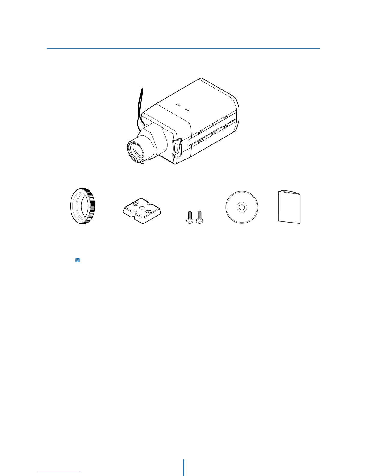
The C-Lens and CS-Lens are not included in the product package. C-Lens and CS-Lens is optional.
Manual CD
Please check if camera and accessories are all included in the product package.
Camera
Camera Holder MountC-Mount Adaptor Camera Holder
Screw-2pcs
4
Page 5
Part Name
Introduction -
2
1
5
3
4
6
7
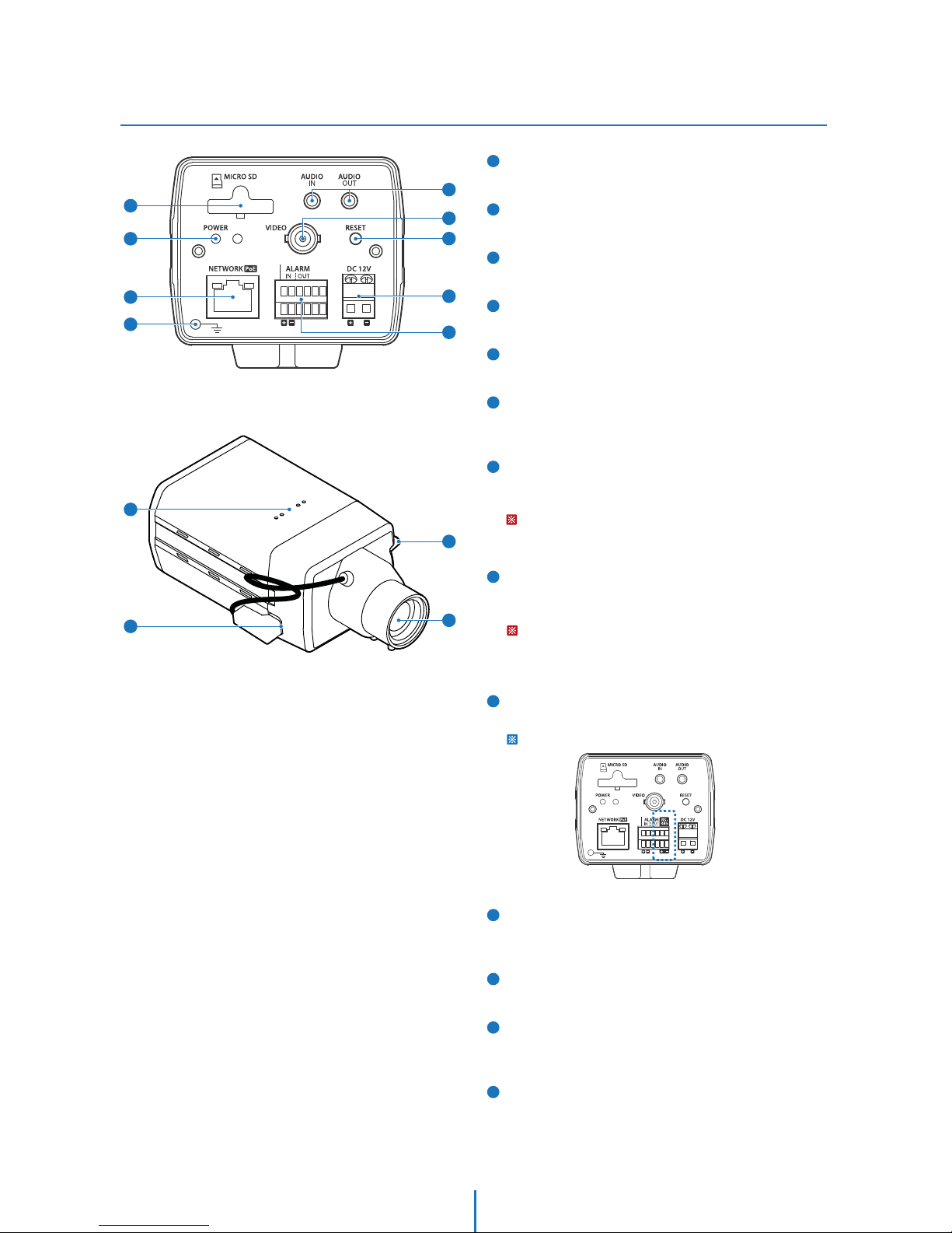
Micro SD Memory Card Slot
Covers the inner cover, lens, and main body to protect them.
Power Indicator
When the power turns on, the indicator will light on.
RJ-45 Connector
Used to connect a PoE or LAN cable.
GND
Used for earth-grounding.
Audio In/Out Port
Used to connect the audio in/out cable.
BNC Video Port
Used to connect video output device such as monitor using
the BNC coaxial cable.
Factory Reset Switch
All the settings will be restored to the factory default. Power
On the unit and push the switch for 5 seconds.
WARNING:
YOU WILL LOSE ALL DATA THAT HAD BEEN ENTERED PREVIOUSLY AND
THE IP DOME CAMERA WILL BE SET TO ITS FACTORY RESETS.
8
9
10
11
12
13
Power Port
Use the screwdriver to connect each line (+, –) of the power
cable to the corresponding power port of the camera.
WARNING:
Be careful not to reverse the polarity when you connect the power cable.
You can also use a router featuring PoE (Power over Ethernet) to supply
power to the camera.
Alarm Input/Output Port
Used to connect the alarm input/output signal.
Only 2M camera support the RS-485port.
Camera Holder (Mount) Holes
Used when you mount the camera onto the bracket by
fixing the camera holder (mount) adaptor with the bracket.
Lens Connector Port
Installed on the lens adaptor.
Back Focus Conctrol Lever
Used to connect the lens connector which output the power
and control signal to control the iris of lens.
Auto Iris Lens (Optional)
Used to control back focus for the lens.
Rear Side
Front Side
9
8
7
5
6
1
2
3
4
10
11
12
13
5
Page 6

Introduction -
Specication
Features and specications are subject to change for further improvement without any notice
Model Number IPC2
Image Sensor 1/2.8” 2MP CMOS
Resolution 2MP
Minimum Illumination
Colour: 0.5 Lux
B&W: 0.01 Lux
Day / Night AUTO / DAY / NIGHT
Focus Manual
Shutter Speed 1/25 ~ 1/30,000 Sec
AGC YES
WDR YES
BLC YES
DSS YES
DNR YES
Sensor I/O 1 Input / 1 Output
Video Output BNC: VBS 1.0 Vp-p
Material Aluminum Die-Casting
Video Compression H.264 / MPEG4 / MJPEG
Video Streaming VBR / CBR
Video Resolution 1080p / 720p / D1 / CIF / QCIF
Frame Rate 30 fps for 1080p
Audio Compression Two Way, G.711 PCM. μ-law 64kbps 8kHz
Local Storage SD Card (Not Included) - JPEG Capture Only
Power DC12V / PoE
Temperature -10°C ~ 50°C
Support Protocol IPV4 / IPV6 / DDNS / SECURITY
Onvif YES
Dimensions (W x H x L) 75 x 60 x 125 mm
Weight 0.45Kg
6
Page 7
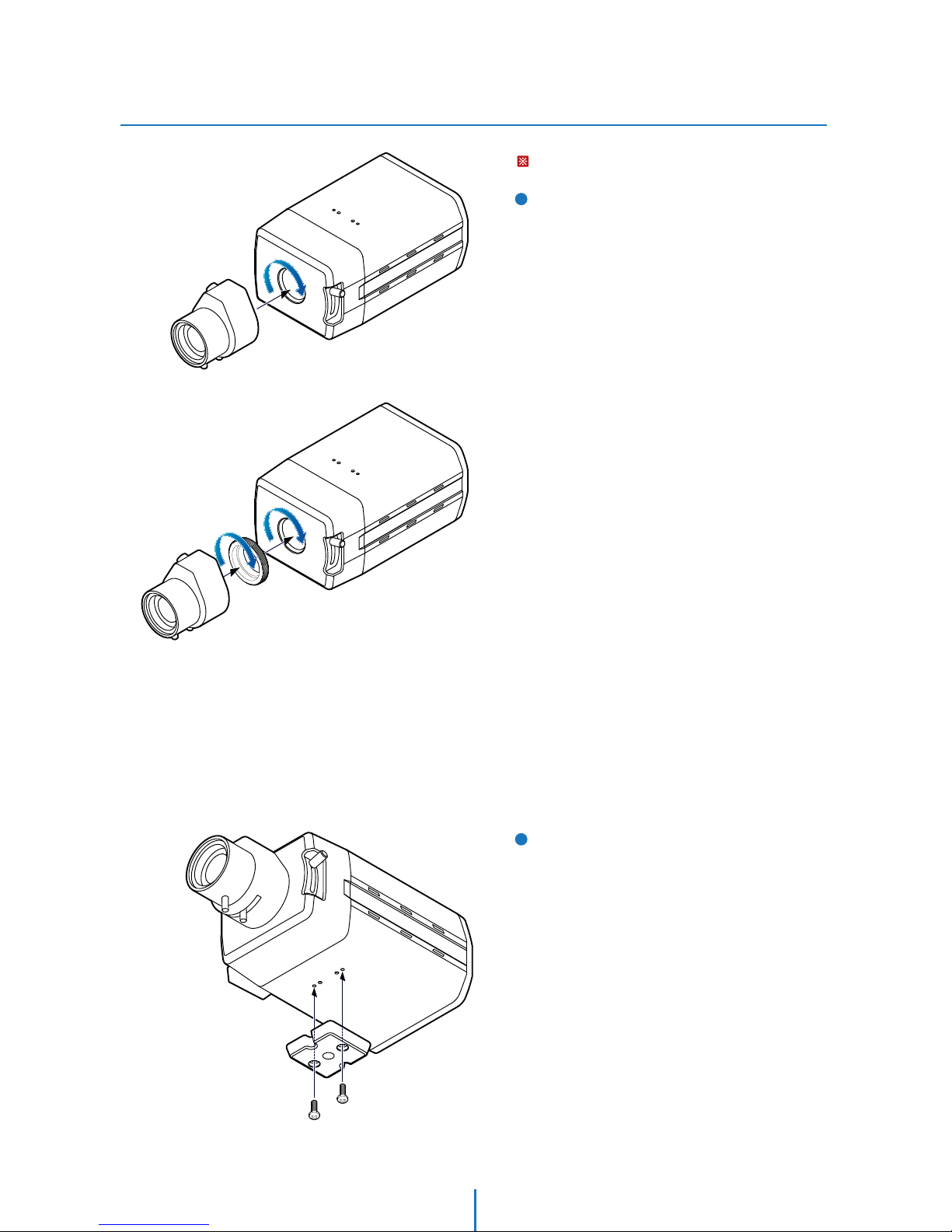
Installation
Installation -
2
1
Disconnect the power before proceeding.
Mounting the Lens
CS-Lens: Turn the optional CS-Lens clockwise to
insert it.
C-Lens: Turn the C mount adaptor clockwise to insert
it and do the same with the C-Lens.
CS-Lens
C-Lens
Fix the Camera Holder
By tightening two camera holde screws provided,
attach the camera holder on the camera.
7
Page 8
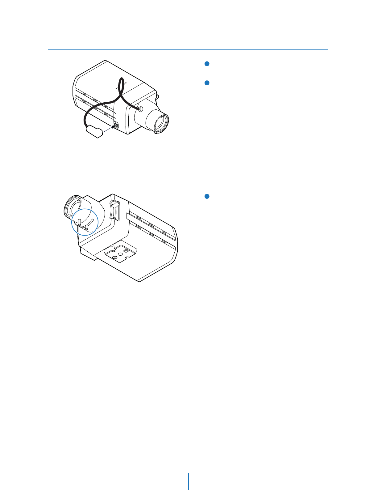
3
5
4
Adjusting Zoom and Focus
By turning screws of the lens, adjust the Zoom and
Focus after setting the position and view angle of
camera.
Lens Connector
Connection Lens Connector
Connect the lens control cable to the lens connector.
Connecting Cables
Connect the power, video, audio, alarm and network
cables respectively. See the section ‘Installation Cabling’ for detail.
Installation
Installation -
8
Page 9
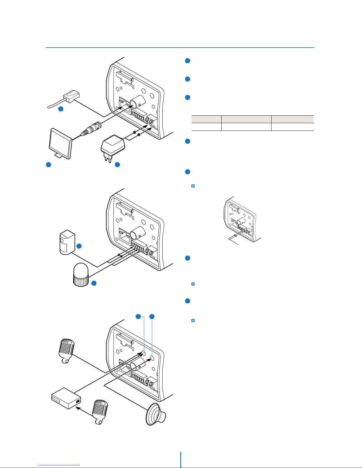
4
5
6
7
Sensor/Alarm Input
It connects to IR sensor, IrDA sensor or door switch. If the
sensor is activated, it can activate to move camera to the
specific angle and to connect the alarm device.
Relay Output
It connects to the alarm lights, siren or lamps.
RS-485(2M Camera Only): Controls with device using RS-485
communication standards.
Audio In
Connect the ‘Audio In’ port of the camera to the
microphone directly or ‘Line Out’ port of the amplifier
connected with microphone.
If the microphone is connected directly, the microphone with the
embedded amplifier such as condenser mic. needs to be used.
Audio Out
Connect the ‘Audio Out’ port of the camera to the ‘Line In’
port of the speaker.
If the speaker without the amplifier is connected to Audio Out
port, it doesn’t work properly. Therefore, the speaker with the
amplifier or the separate amplifier is needed.
1
3
2
Network Connection
Connect the crossover cable into the RS-45.
Video Output(BNC Cable)
The BNC cable is used to connect to a monitoring display.
Power Connection
Please, check the voltage and current capacity of rated
power carefully.
Rate Power Current Consumption
DC 12V 5.5W
PoE
IEEE802.3af Class 0
2
Video Output(BNC)
3
Power
1
Network
Connection
4
Sensor/
Alarm Input
5
Relay Output
Amplifier
Mic.
Speaker
Line In Connection
Line Out Connection
Direct Connection
Mic.
RS-485
Cabling
Installation -
7
Audio Out
6
Audio In
9
Page 10
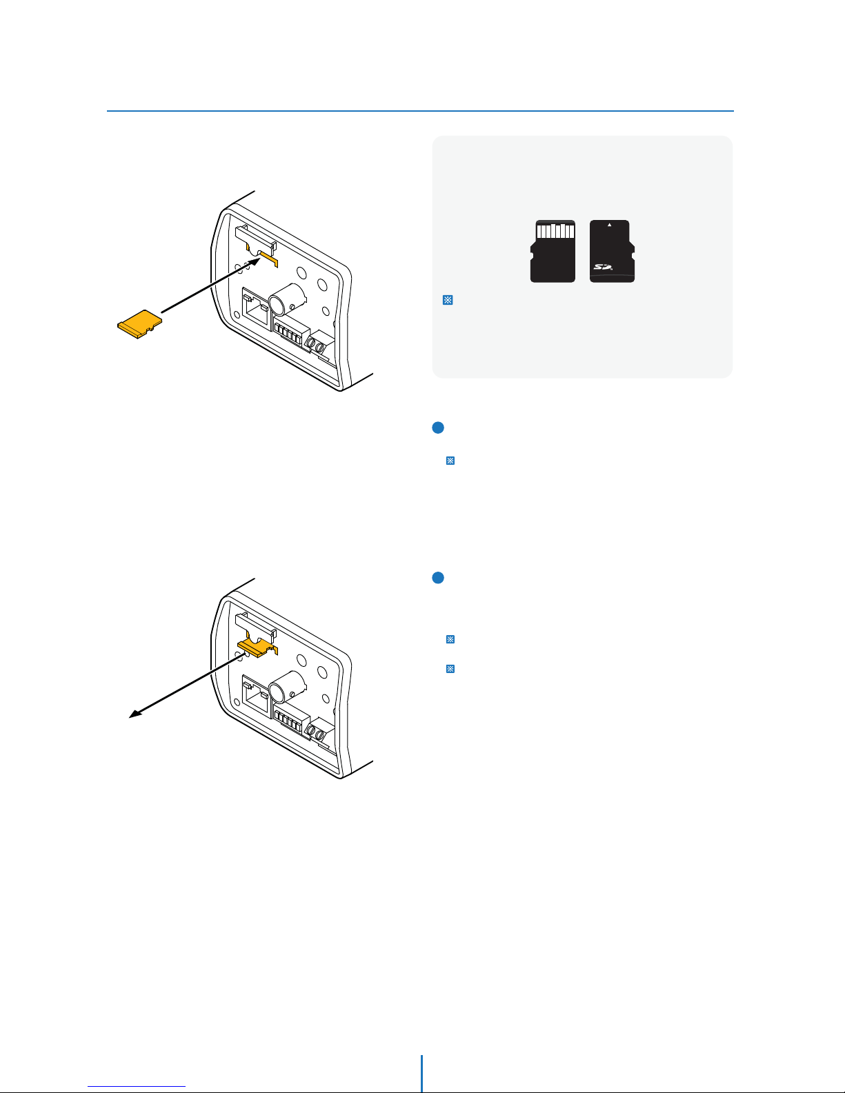
Micro
Inserting/Removing an SD Memory Card
Installation -
1
Inserting an SD Memory Card
Insert the SD card in the arrow direction.
Don’t insert the SD memory card while it’s upside down by force.
Otherwise, it may damage the SD memory card.
2
Removing an SD Memory Card
Removing an SD Memory Card Gently press down on the
exposed end of the memory card as shown in the diagram
to eject the memory card from the slot.
Pressing too hard on the SD memory card can cause the card to
shoot out uncontrollably from the slot when released.
If you have saved data in the SD memory card, removing the SD
memory card prior to setting record to OFF will cause damage to
the data stored in the card.
Recommended SD Card Specication (Not Included)
- Type: Micro SD (SDHC)
- Manufacturer: Transcend, Kingston, Toshiba, Sanddisk
- Capacity: 4~16G
- Class: over Class 6
The memory card is an external data storage device
that has been developed to oer an entirely new way
to record and share video, audio, and text data using
digital devices.
10
Page 11
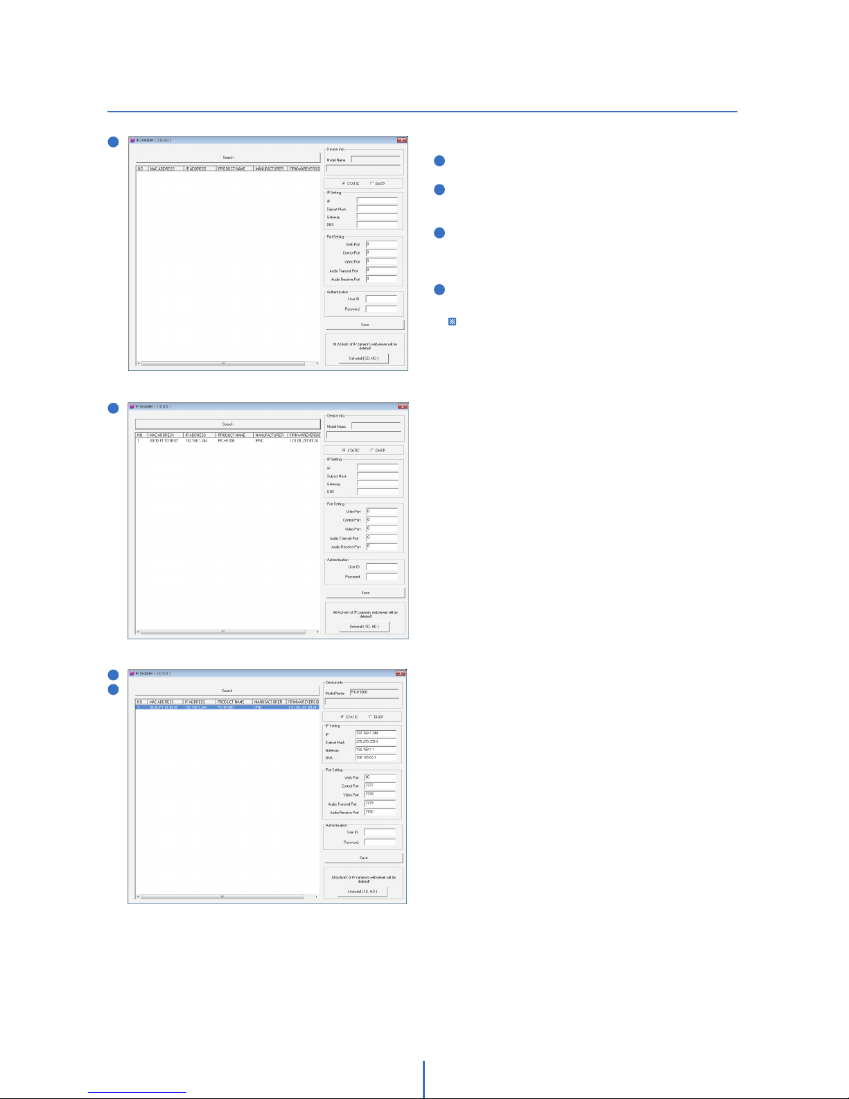
IP Installer
Network Setup -
3
4
1
1
2
3
4
2
Manual CD > Software > Run ‘IP Installer.exe’
If you run the program, it will automatically search all IP
cameras connected to the current PC within LAN.
If you click one of the lists, corresponding information on
IP and port setting will be shown on the right. Enter
suitable information for installation setting.
After changing IP and Port setting, enter ID and PW for the
camera and then click the “Save” button.
It takes the camera one and a half minutes and it will
automatically reboot after saving it.
1. Run IP Installer
11
Page 12
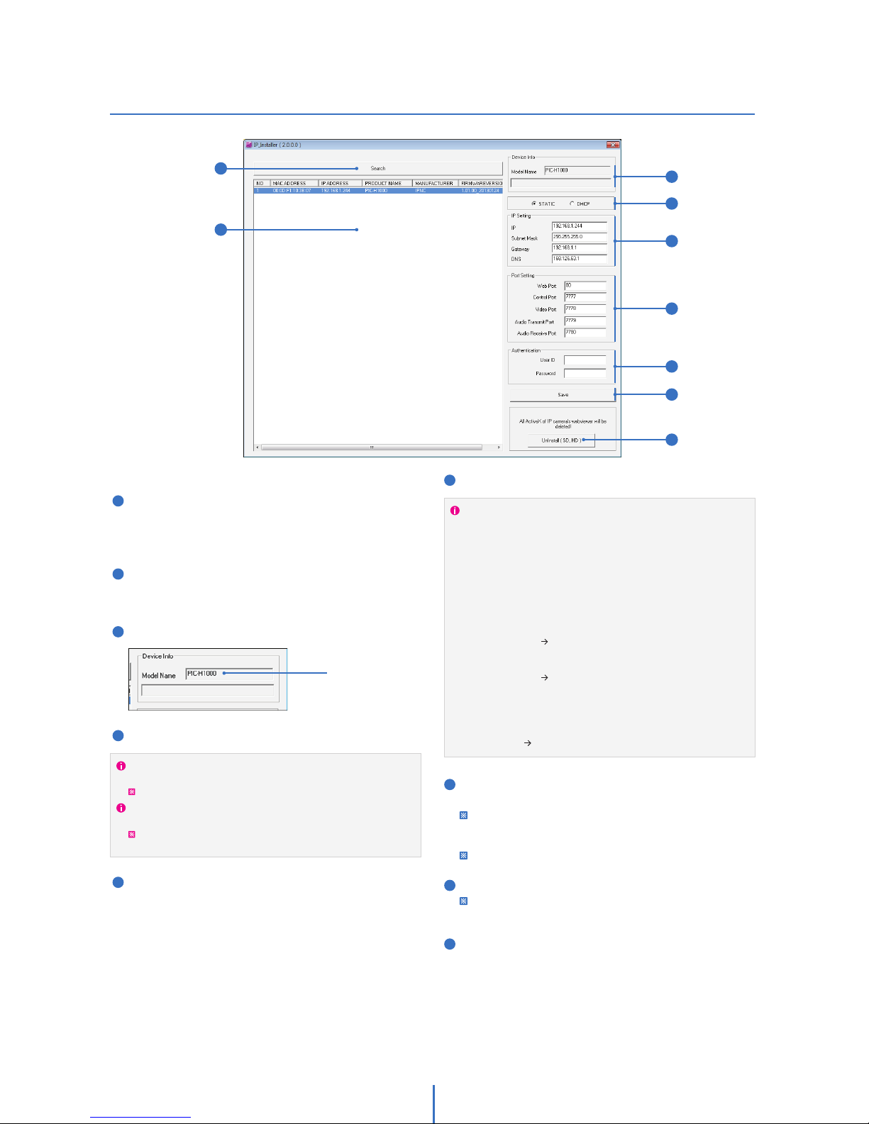
IP Installer
Network Setup -
You don’t need to change the setting when connected to IP
camera via IP router or within LAN. However, a port forwarding
is required to allow remote access to the IP camera within LAN
by external host. For the setting, refer to instructions of the IP
Router.
Case 1. Connection within LAN / via IP Router,
1) Open the Internet Browser.
2) Enter an IP address and HTTP port into the address bar.
Case 2.1) HTTP default value is not 80
e.g.) IP: 192.168.1.80, HTTP: 8080
http://192.168.1.80:8080
Case 2.2) HTTP default value is 80
e.g.) IP: 192.168.1.80, HTTP: 80
http://192.168.1.80
Case 2. Remote Connection by external host after port forwarding,
1) Open the Internet Browser.
2) Enter an IP address and HTTP port into the address bar.
e.g.) IP: 192.168.1.100, HTTP: 8888
http://192.168.1.100:8888
6
7
8
9
Port Setting: Configure Port Setting.
Authentication: Before saving settings, enter an ID and PW.
Default ID and PW are admin; admin.
For security reasons, recommend changing the ID and PW. For
configuration, go “Webviewer>Administrator tool( )>System>
Users”.
When factory reset the camera, both ID and PW are also reset.
Save: Click this button to save all settings.
It takes the camera one and a half minutes and it will reboot after
saving it automatically.
Uninstall (SD, HD): To make webviewer work, Active X should
be installed to PC. The Webviewer might not be seen because
of crash between previous installed one and this one.
Then click this button to uninstall/remove the previous one
and reinstall one of webviewer.
1
2
3
4
5
Search: IP installer searches and lists all IP
cameras connected to the current PC within
LAN. Re-click “Search” unless all IP cameras
are listed.
IP Camera List: Searched IP cameras are listed.
By clicking it, you can see information on the
camera name, IP and port setting on the right.
Device Info: Model name is shown.
Network Type: Choose Network Type.
IP Setting: Configure IP setting.
2. IP Installer details
Normally choose Static IP. In case that it is dynamic and get it via
DHCP server, choose Dynamic IP.
Choose Static IP when sharing IP address via IP router.
Enter suitable information on IP address, Subnet Mask, Gateway,
DNS for installation setting.
If it is Static IP, you can get the information from the Internet service
provider.
1
2
Model name
3
4
5
6
7
8
9
12
Page 13
Quick Start of Network Connection
Network Setup -
Please follow the steps below to complete
the initial setup of the network function.
In order to communicate with the IP Camera, access to
PC/laptop and configure the PC.
Keep a record of TCP/IP properties of the PC. (IP address,
subnet mask, gateway, DNS, etc.)
1.
Please do not power on the IP Camera until instructed.
Temporarily disable any proxy servers configured in internet
Explorer.
If connecting the IP Camera directly to a modem, power down
and reset the modem. Leave the modem powered down until
configurations are finalized with the IP Camera and the IP Camera
has been correctly connected to the modem.
Change the IP address of the host PC to 192.168.1.11 and
subnet mask to 255.255.255.0 (leave all other entries blank)
Connect the IP Camera to your PC’s Ethernet port via the
supplied crossover cable. (It does not matter what end is
used for the PC)
Power on the IP camera using the supplied power adapter.
After 1 minute of power, verify a flashing ACTIVE indicator
and a flashing or solid LINK indicator. After the
corresponding indicator lights are properly displayed, open
Internet Explorer.
Type - http://192.168.1.80 (the default IP of the IP Camera)
into your address bar.
Default ID/Password to access IP Camera are both the
word: admin.
Familiarize yourself with the Viewer Interface Screen.
Locate the TCP/IP configuration under Setup. Supply the
same ID and Password to enter Setup. (admin : admin)
Select STATIC under ‘Network Type’ . You will select Dynamic
only if you are connecting the IP Camera directly to your
cable/DSL/Broadband modem and your Internet Service
Provider is supplying a dynamic address.
2.
3.
4.
5.
6.
7.
8.
9.
10.
If your PC obtains its IP address automatically, there is no need to
record any information.
If you have a network with other devices (such as PC/laptop, etc.)
or a router, you will NEVER select Dynamic.
Configure the IP Camera’s TCP/IP settings as you normally
do any other PCs on your network by providing a proper IP
address, subnet mask, default gateway, and DNS server.
11.
If this is a stand-alone unit with a direct connection to cable/DSL/
Broadband modem, input the addresses you have received from
your ISP. If you have received no IP address from your ISP, select
Dynamic and choose the proper settings.
Current TCP/IP Settings
IP Address
Subnet Mask
Default Gateway
Primary DNS Server
Secondary DNS Server (Option)
Access your IP Camera via the Internet :
If you use a static IP address assigned by your ISP
1) Open Internet Explorer.
2) Type the IP of the IP Camera.
3) If you use a router, type the routers’ static IP and the web port
number of the IP Camera.
If you have a dynamic address provided by your ISP
1) Open Internet Explorer and visit the DDNS website.
2) Register the IP Camera.
3) Reboot the IP Camera.
4) Give the DDNS server 10 minutes to locate your IP Camera’s
IP information.
5) Click the refresh button in the Internet Explore.
6) After your camera is connected, select your camera.
15.
The IP Camera utilizes five TCP ports - a Web Port, a Video
Port, a Control Server Port, Audio ports. A Web Port is to
utilize Internet Explorer, a Video Server port is to support
the streaming video, a Control Control Port is to transmit to
control commands and Audio Ports are to transmit and
receive Audio data. If the IP Camera will be directly attached
to a cable/DSL/Broadband modem or it has been assigned a
static IP from your ISP, then leave the default port settings.
If you are installing the IP Camera on a network, you must
define a Web Port other than 80. The other ports, a Video
Port, a Control Port, Audio Ports can remain unchanged.
If the IP Camera is connected to a network which utilizes a
router, you must have Port Forwarding configured on your
personal router to forward all ports to the IP address you
have assigned the IP Camera.
After configuring Port Forwarding on your router
(if necessary), you may access your IP Camera on your local
network by opening Internet Explorer and specifying the IP
address and Web Port that you have assigned to the IP
Camera.
12.
13.
14.
Example: http://192.168.0.200:8888
If you leave your Web Port set to 80, you don’t need to specify
the port in the Address Bar to access to your IP Camera.
13
Page 14
Initial Setup via a Crossover Cable
Network Setup -
This section provides a guide on how to
connect the IP Camera to your PC/Laptop for
initial setup.
Please follow the instructions in the order
below without skipping steps. Do not supply
power to the IP Camera until instructed.
In order to access the IP Camera’s firmware
you will need to connect the Video Server to
a PC or Laptop directly via the supplied
crossover cable.
Before you begin, you must determine the current network/
INTERNET (TCP/IP) settings on the PC or laptop. Write down
your entries below for quick reference.
1.
You will have to click ‘Yes’ twice to two individual prompts. This
allows your video to be displayed in Internet Explorer.
Current TCP/IP Settings
IP Address
Subnet Mask
Default Gateway
Primary DNS Server
Secondary DNS Server (Option)
To make the IP Camera to communicate with your PC,
change your PC’s IP address and subnet mask.
2.
Now you will be able to see the login screen for the IP
Camera.
7.
The default ID and Password are both the word ‘admin’
(without the “ ”)
At any time if you are prompted to download ActiveX controls,
Click ‘Yes’ as all contents are safe.
8.
9.
You should change your IP address to 192.168.1.11 and change
the subnet mask to 255.255.255.0
Leave all other entries (Default Gateway, DNS Servers, etc.) blank.
For information on how to change your IP address and subnet
mask, see Appendix B.
After you have made the changes to your IP address and
subnet mask, you may attach the IP Camera to your PC via
the supplied crossover cable. Plug-in either end of the
crossover cable into the PC’s network card and the other end
into your IP Camera.
After connecting the PC and IP Camera using the crossover
cable, power on the IP Camera by plugging in the power
supply shipped with the IP Camera.
No longer than 1 minute after powering on the IP Camera,
verify that the ACTIVE indicator light is flashing, and the LINK
indicator light is flickering or solid. No longer than 1 minute
after power on the IP Camera, verify that the ACTIVE indicator
light is flashing and the LINK indicator light is flickering or
solid. If they are not, read the FAQ.
3.
4.
5.
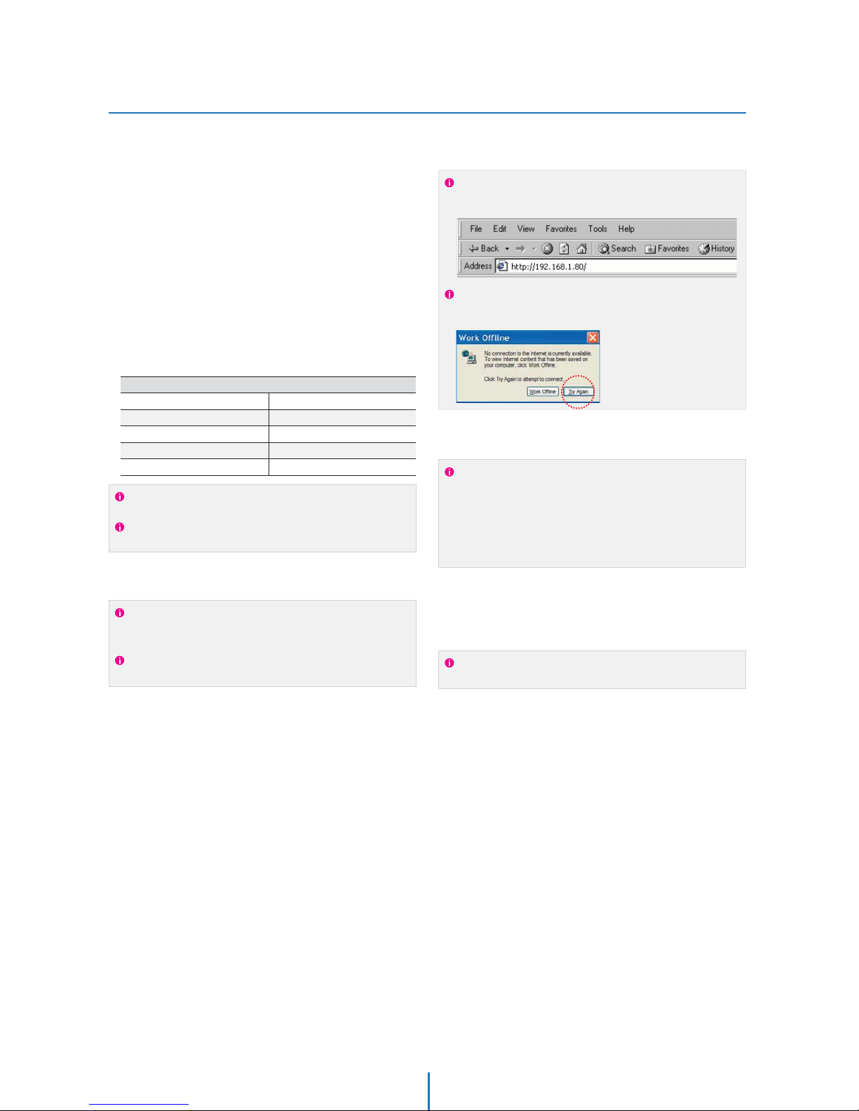
Open Internet Explorer and type the IP address of 192.168.1.80
(default IP of the IP Camera from the factory) into the Address Bar
of the web browser (as seen below). Press Enter.
If a message box similar to the image below appears, choose
‘Try Again’. The message will vary depending on the operating
system.
The 3 authorities are available :
Administrator, Operator and Viewer. The authority setup is
available in Setup.
t7JFXFS 0OMZNPOJUPSJOHJTBMMPXFE
t0QFSBUPS Most of the functions are allowed except
‘Setup’.
t"ENJOJTUSBUPS"MMGVODUJPOTBSFBMMPXFE
For information on how to determine your currents settings, see
Appendix A.
If you are obtaining an IP Address automatically, there is no need
to write down the information.
Now you will be able to access the viewer software within
the IP Camera.
6.
14
Page 15

DDNS Registration
Network Setup -
If you have DYNAMIC IP service from your
Internet Service Provider (ISP), you can’t tell
the current IP address of the IP Camera.
To solve this problem, you have to register to
our DDNS service.
At first, you have to check if you are using
dynamic addressing. If so, register your IP
Video Server on our DDNS website before you
configure, setup, or install the IP Camera.
Even though your IP is not dynamic, you will
get benefit if you register to DDNS. In this
case, just remember ‘alex.net4c.net/gate1’
instead of complicated series of numbers like
http://201.23.4.76:8078.
For more details, contact our Support Center.
To register IP Camera to DDNS, ‘Serial No.’ of the IP Camera should
be known. The ‘Serial No.’ can be found in section 6 ‘Setup - DDNS’
menu.
To use a public DDNS called ‘dyndns’ or ‘no-ip’, refer to the detail
information on how to use the service.
(Visit the web site : http://www.dyndns.com or
http://www.no-ip.com)
15
Page 16
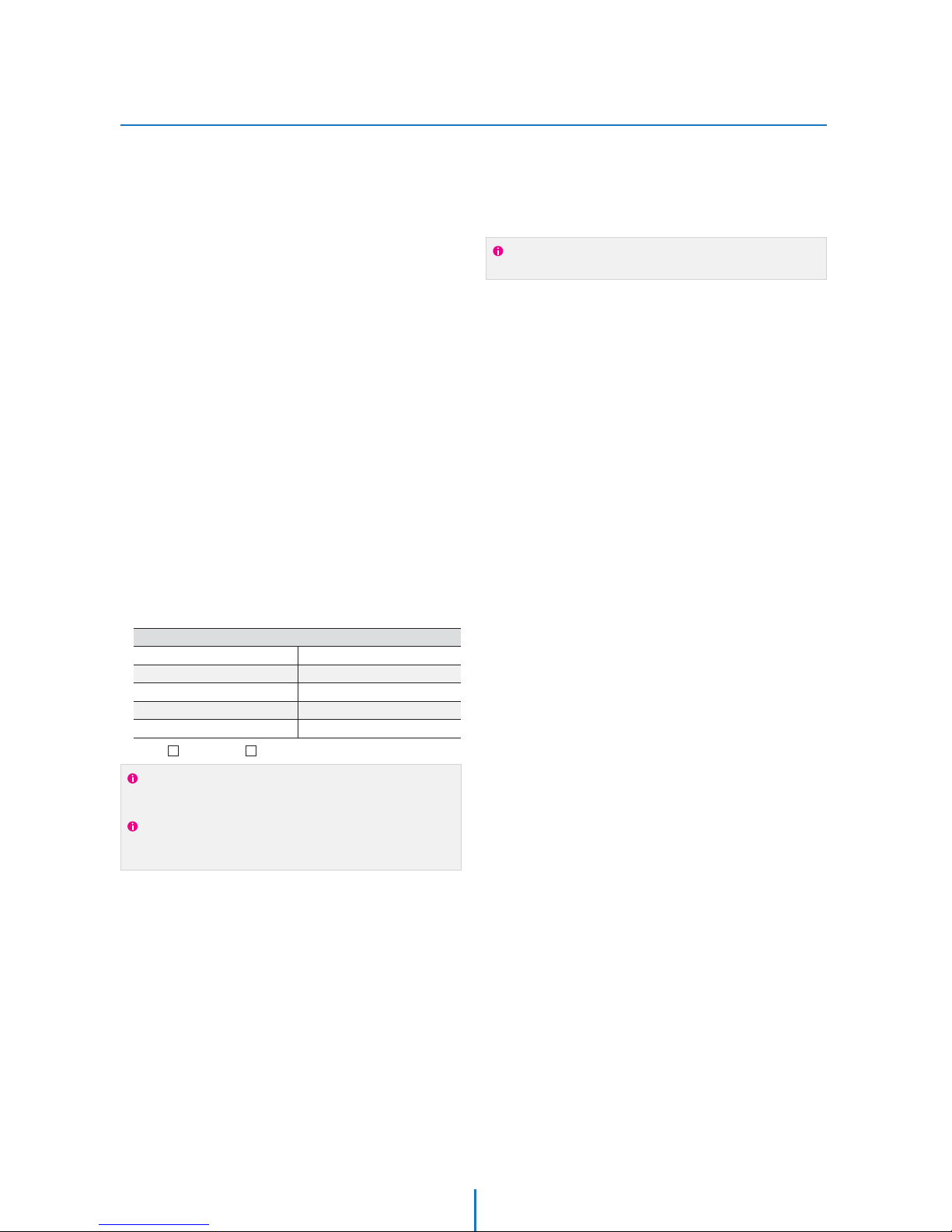
Guide to Network Environment
Network Setup -
Please configure the IP Camera at the
installation site. You must determine your
network scenario in order to configure the IP
Camera with the proper TCP/IP settings.
This tutorial will guide you through the
process. Before actually configuring the IP
Camera, determine settings to be applied.
Record those settings to be used to configure
your IP Camera for reference.
When configuring your IP Camera, treat the
IP Camera as another PC on your network.
You will assign it several addresses and other
TCP/IP properties to match your current
network.
This step-by-step tutorial will teach what IP
addresses and network configurations should
be assigned based on the network scenario.
If you were not given any IP addresses or the ISP was responsible
for the setup and installation of your Internet connection, go to
step 2.
If you are not using a router on your network, your ‘Current TCP/IP
Settings’ (from the previous section) and ‘Assigned IP Addresses
from My ISP’ will be exactly the same.
Before you begin, locate any information and settings
received from your Internet Service Provider (ISP). You may
need to refer to these IP addresses at a later time during the
configuration.
1.
You must determine whether the IP address is STATIC or
DYNAMIC. At this moment, you are only concerned about the
ISP. Did they provide you with a STATIC or DYNAMIC address?
If you are unsure, contact your ISP.
Configure your IP Camera’s TCP/IP settings for network
connectivity by selecting Setup from the main interface and
selecting TCP/IP located on the left of the Setup screen.
If prompted for ID and Password, use ‘admin’ for both entries.
The default web port number is 80. If port 80 is blocked by
the ISP, a value between 1025 ~ 60000 should be used. If TCP
port 80 is blocked, consult the ISP
2.
3.
4.
Current TCP/IP Settings
IP Address
Subnet Mask
Default Gateway
Primary DNS Server
Secondary DNS Server (Option)
Static Dynamic
5. The following descriptions are several basic network
scenarios. Determine which scenario describes your network.
If your network does not match one of the scenarios below
and you are unsure how to setup your IP Camera, contact
your network administrator and then call our Support Center.
You cannot control the rectangular gray areas and only the ISP
has access to the devices.
16
Page 17
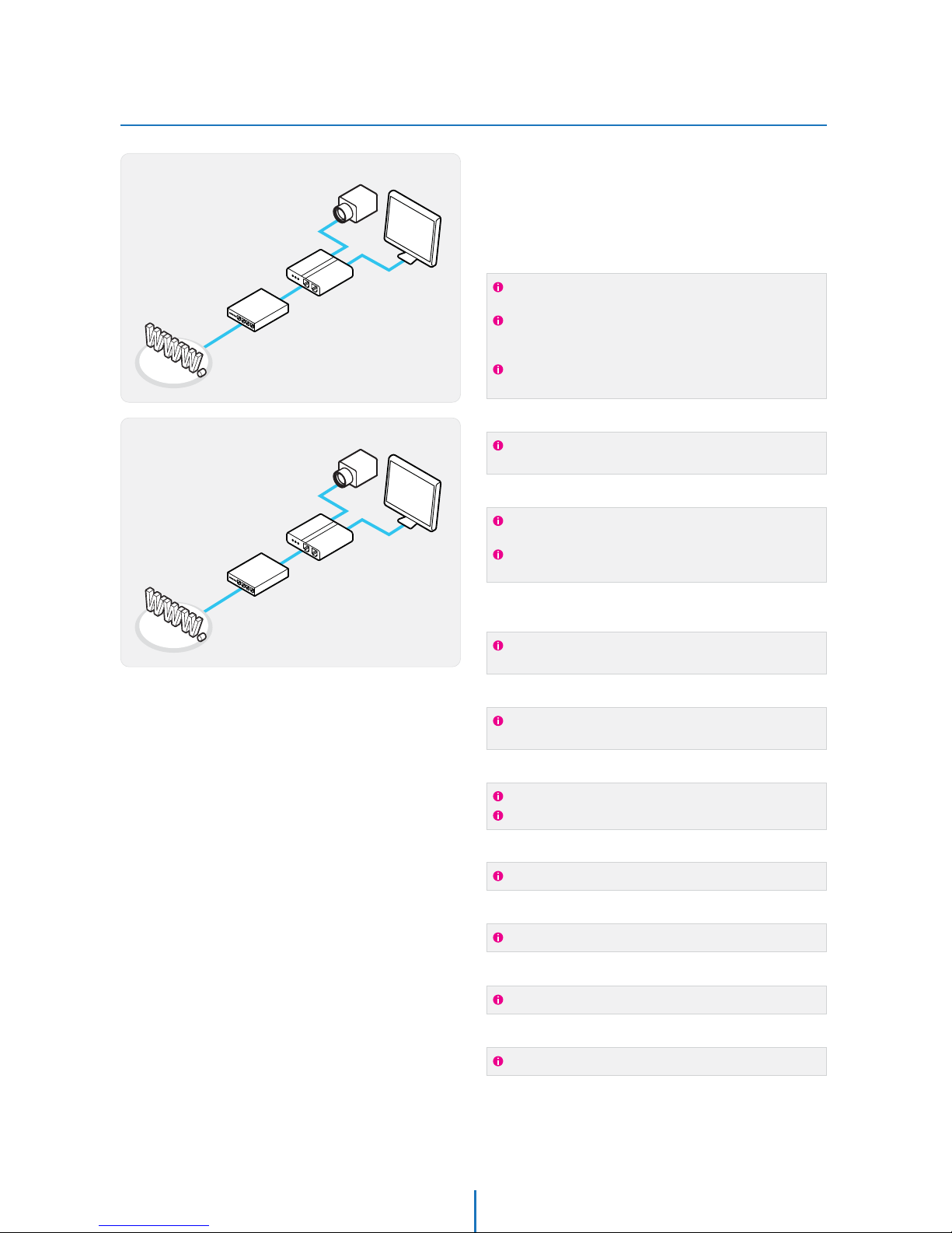
Setup Case A, B
Network Setup -
Case A:
Dynamic IP +
Personal Router [Most SOHO]
Personal Router
W/Intergrated Switch
Cable/xDSL Modem
(ISP Provided)
Phone Line
or CATV
PC
Internet
Case B:
Static(Fixed) IP +
Personal Router [Ecient]
PC
Personal Router
W/Intergrated Switch
Gateway or Router
at ISP
Public Line
Internet
Configure your IP Camera's TCP/IP properties
as follows :
STATIC (even though you have Dynamic IP from
your ISP, use STATIC on the IP Camera)
Network Type :1.
A private IP address such as
192.168.0.200 (Example)
Internet Address :2.
You need to assign an IP address to the IP Camera just as you do
with PC.
The IP address you assign must be unique to your network and
match your network as well. For information on how to choose
a unique IP and match your network, read the FAQ.
The IP address you assign must be a private IP. For information
on how to choose a private IP please, read the FAQ.
255.255.255.0 (Example)
192.168.0.1 (Example)
Subnet Mask :3.
You must use the same subnet mask as the one you noted under
‘Current TCP/IP Settings’.
Default Gateway :4.
This IP address must be the IP address of your router.
(private or LAN side)
Use the same Default Gateway you noted under ‘Current TCP/IP
Settings’.
Use the 1st DNS Server from ‘Assigned IP
Address from My ISP’.
Preferred DNS Server :5.
Use the DDNS server.
DDNS Server :6.
This is the same site you will register later to accommodate
dynamic IP from your ISP.
8888Web Port :7.
Do not use the default port 80 as this number must be changed.
You may select any number between 1025 ~ 60000.
7777Control Port :8.
You may select any number between 1025 ~ 60000.
7778Video Port :9.
You may select any number between 1025 ~ 60000.
7779
7780
Audio Transmit Port :10.
You may select any number between 1025 ~ 60000.
Audio Receive Port :11.
You may select any number between 1025 ~ 60000.
If you did not receive any IP addresses from your ISP, contact
the ISP and acquire the IP address of their DNS server.
Camera
Camera
17
Page 18
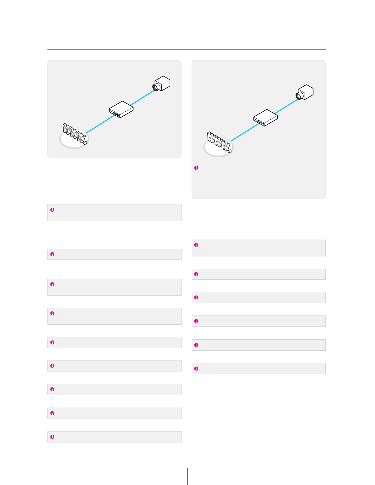
Setup Case C, D
Network Setup -
To connect the IP Camera directly to a modem, power down
and reset the modem. Leave the modem powered down until
configurations are finalized with the IP Camera and the IP
Camera has been connected correctly to the modem. Then
power on the modem, followed by the IP Camera.
Cable/xDSL Modem
(ISP Provided)
Phone Line
or CATV
Internet
Internet
Public Line
Gateway or
Router at ISP
STATICNetwork Type :1.
A static IP address received from your ISP such
as 24.107.88.125 (Example)
Internet Address :2.
You need to assign an IP address to the IP Camera just as you do
with PC.
Subnet mask assigned from your ISP such as
255.255.255.240 (Example)
24.107.88.113 (Example)
Subnet Mask :3.
Default Gateway :4.
Use the assigned default gateway from your ISP
Use the 1st DNS Server from ‘Assigned IP
Address from My ISP’
Preferred DNS Server :5.
Use the DDNS server
DDNS Server :6.
This is the same site you will register later to utilize our DDNS
service.
80Web Port :7.
You may select any number between 1025 ~ 60000.
7777Control Port :8.
You may select any number between 1025 ~ 60000.
7778Video Port :9.
You may select any number between 1025 ~ 60000.
7779
7780
Audio Transmit Port :10.
You may select any number between 1025 ~ 60000.
Audio Receive Port :11.
You may select any number between 1025 ~ 60000.
If you have not received any IP addresses from your ISP, contact
them to acquire the IP address of their DNS server.
DYNAMICNetwork Type :1.
Use the DDNS serverDDNS Server :2.
This is the same site you will register later to accommodate
dynamic IP from your ISP.
80Web Port :3.
You may select any number between 1025 ~ 60000.
7777Control Port :4.
You may select any number between 1025 ~ 60000.
7778Video Port :5.
You may select any number between 1025 ~ 60000.
7779
7780
Audio Transmit Port :6.
You may select any number between 1025 ~ 60000.
Audio Receive Port :7.
You may select any number between 1025 ~ 60000.
Configure your IP Camera's TCP/IP properties
as follows :
Configure your IP Camera's TCP/IP properties
as follows :
Case C:
Static(Fixed) IP [Dedicated line directly
to the IP Camera]
Case D:
Dynamic IP + DSL/Cable Modem [Connected
directly to the IP Camera]
Camera
Camera
18
Page 19
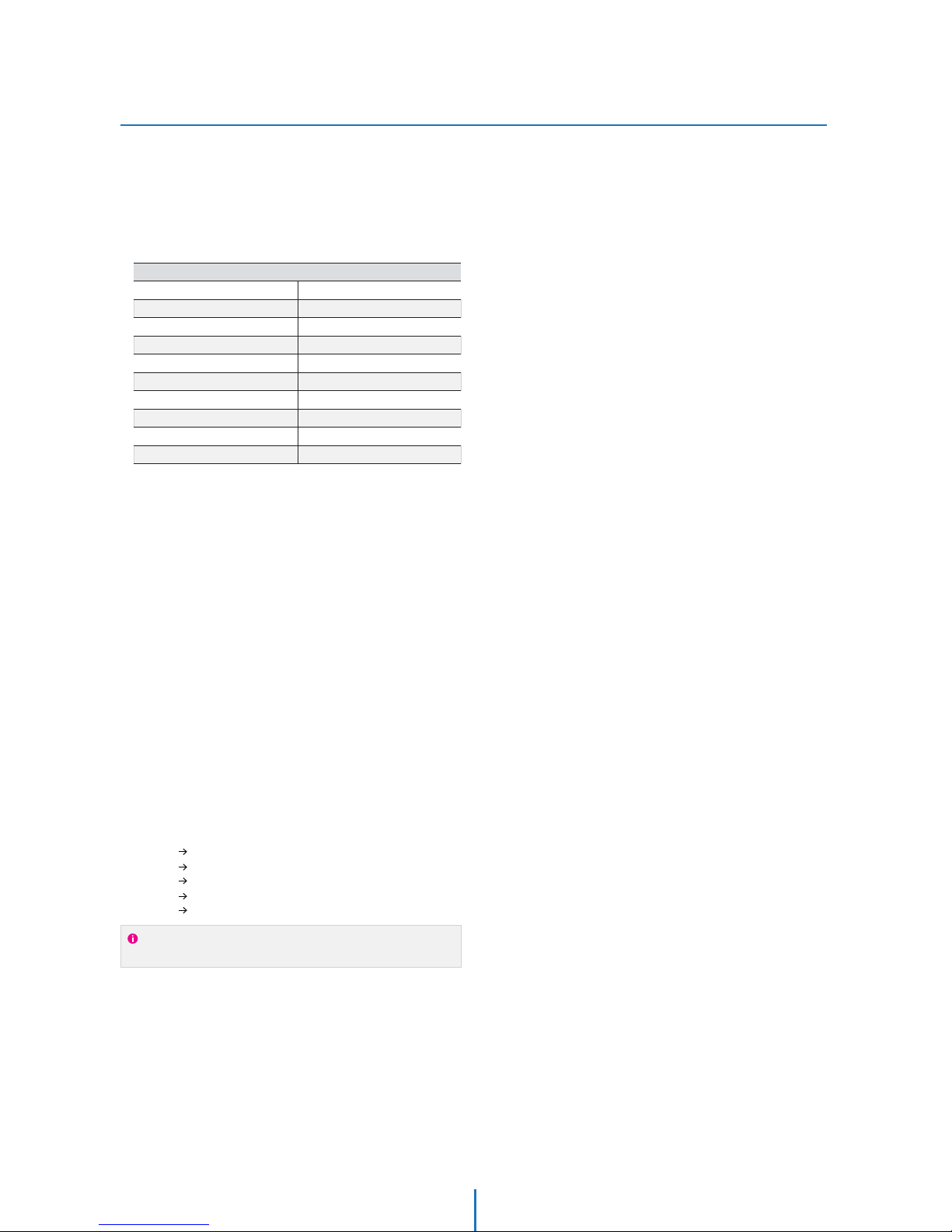
Port Forwarding
Network Setup -
After entering the correct TCP/IP settings, you
are ready for ‘Port Forwarding’(Cases A, B).
Please record the TCP/IP settings of your IP Camera for future
reference. You may need this information to access your IP
Camera and to configure ‘Port Forwarding’.
1.
After clicking ‘Apply’, the system will prompt for a reboot.
Please allow the system 50 seconds to reboot and accept the
changes. After 50 seconds, close the configuration screen.
The view will display ‘Trying to Reconnect’. If the ACTIVE light
on the IP Camera has gone off and is now back on again
flashing, the IP Camera has rebooted. After the system
reboots completely, remove the power supply from the
unit and close Internet Explorer.
Return your PC/Laptop TCP/IP properties to their original
settings.
Before installing the IP Camera, you must use ‘Port
Forwarding’ on your personal router (Cases A, B).
You will need to forward 5 ports:
t8FC1PSU
t$POUSPM1PSU
t7JEFP1PSU
t"VEJP5SBOTNJU1PSU
t"VEJP3FDFJWF1PSU
All the ports will be forwarded to the IP address you
assigned to the IP Camera.
In the example above, you would forward:
t
t
t
t
t
2.
3.
4.
IP Camera TCP/IP Settings
IP Address
Subnet Mask
Default Gateway
Preferred DNS Server
DDNS Server
8FC1PSU
Control Port
Video Port
Audio Transmit Port
Audio Receive Port
For information on how to use ‘Port Forwarding’, please read
Appendix C.
19
Page 20
Starting IP Camera
Network Setup -
After forwarding correctly the Web Port,
Video Port, Control Port and two Audio Ports
through your router (if applicable), install the
IP Camera in a proper location.
Locate the serial number located on the label attached to the
bottom of the IP Camera, you will need this for DDNS
registration.
Connect the IP Camera to your router or cable/DSL modem
(per your network scenario) via a Cat5/5e UTP Ethernet
network cable.
Supply power to the IP Camera.
After 1 minute, verify the IP Camera indicators:
t"$5*7&'MBTIJOH
t-*/,'MJDLFSJOH4PMJE
"GUFSDPOGJHVSJOH1PSU'PSXBSEJOHPOZPVSDPNQVUFS
(if necessary), access your IP Camera on your local network
by opening Internet Explorer and specifying the IP address
and Web Port assigned to the IP Camera.
1.
2.
3.
4.
5.
Access your IP Camera via the Internet :6.
Examples: http://192.168.0.200:8888 or http://24.106.88.123
If you left your Web Port set to 80, do not need to specify the
port in the Address Bar to access the IP Camera.
If you use Case B, C
1) Open Internet Explorer.
2) Type the IP of the IP Camera.
If you use Case A, D
1) Open Internet Explorer.
7JTJUUIF%%/4XFCTJUF
3) Register the IP Camera.
4) Give the DDNS server 10 minutes (MAX) to locate your IP
Camera’s IP information. You may reboot the server to send an
immediate request to our DDNS server.
5) After your camera is connected, select your camera.
The difference between B and C is that B needs to set the port
forwarding.
Since the type of DDNS differs from the service type, refer to
the related service site.
20
Page 21
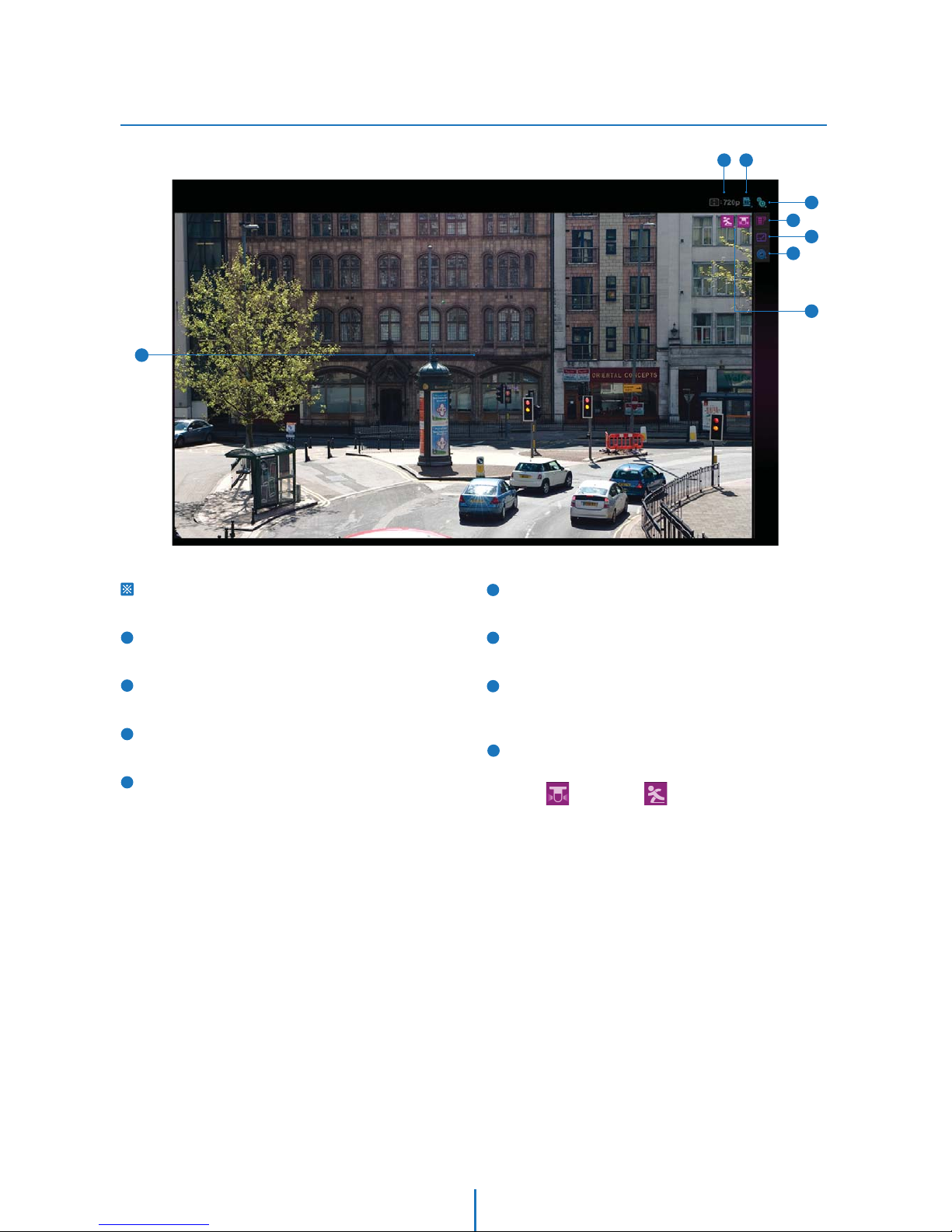
Basic Screen
Web Viewer Screen -
1
2
5
7
3
4
8
6
2
1
7
8
3
4
5
6
Web viewer is optimized with Windows XP or above version
and explorer browser.
Live video display. This is the region for live video stream
from the camera.
Resolution. The resolution of video that displays currently
on the screen.
SD Card Search. Searching or Playing the Image which
stored in the SD Card.
Setup popup button. Click it to open the Setup page to
setup details of IP camera like Video, Network, Events,
System and etc. See the section ‘Setup’ .
Control tab button. Click it to extend the panel to control
the function of web-viewer. See the next page for detail.
Full screen button. Click it to extend the live video to full
screen. To return to normal mode, press ‘Esc’ or ‘Enter’ key.
Camera Setup popup button. Click it to open the Setup page
to setup details of Lens, White Balance, Auto Exposure, image
Backlight and etc. See the section ‘Camera Setup’ .
Event alert icon. If Alarm in and Motion detection are
detected, below icons will appear.
<Alarm Input> <Motion Detection>
21
Page 22
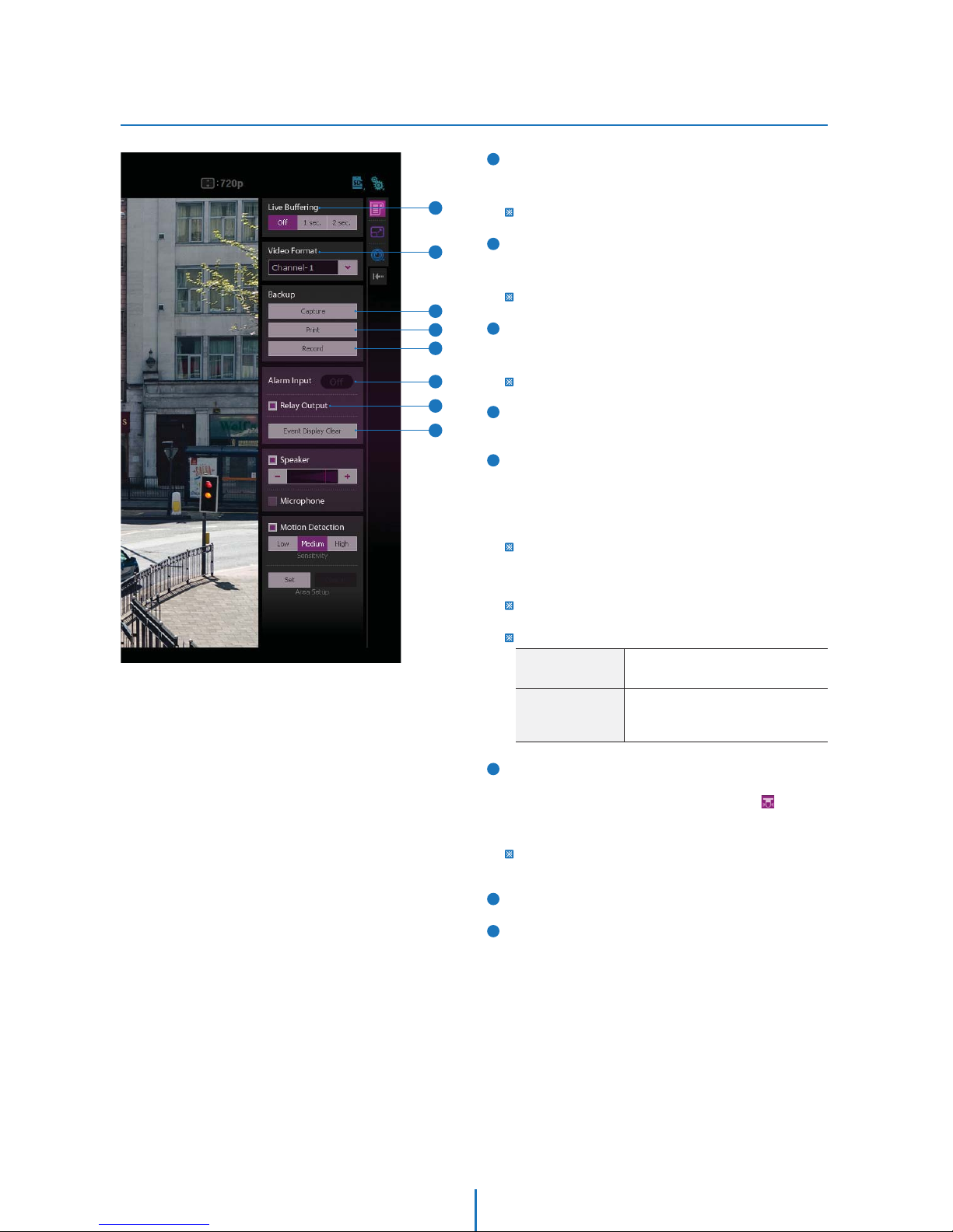
Control Tab
Web Viewer Screen -
2
1
5
3
4
6
When the image goes unsmoothly because of bad network
connection, it stored image during setup time and shows
the image on the live view screen.
User will see the delayed images as much as setup time.
Video stream button. Select a stream produced from the
camera between Stream 1 ~ 3 to display it in the live view
screen.
Refer the ‘Setup > Basic > Video’ to setup the Video Stream.
Capture button. Capture the live video in the form of BMP or
JPG file. The location and file name of image can be decided
after clicking this button.
Refer the ‘Setup > Basic > Backup’ to setup the type of Image.
Print Button. Print current live image to the printer
connected to the PC.
Record Button. If you click this button, the current live video
will be stored as AVI format file in your PC. During the
recording, you cannot change the Video Format. If you
change the Video Format, the recording will be stopped
automatically.
If remained disk space of the HDD drive where the video is
recorded is less than 1GByte, a warning message box regarding
the disk space will be shown and the recording will be stopped
automatically.
To play the recorded video in the Windows Media Player, H.264
codec must be installed.
Recorded files folder
Alarm Input Status. It shows the Alarm Input status. If the
status of alarm input becomes On state, the ‘Off ’ button will
be changed to ‘On’ button and event alert icon( ) is
displayed on the ‘Live video display’. If alarm is removed, the
alarm input status is reset.
Regardless of alarm status, the Alert Icon will remain unless
'Event Display Clear' button is clicked.
Relay Out Button. Enable or Disable relay out function.
Event Display Clear Button. Remove Event Alert Icons result
from Alarm Input or Motion detection.
7
8
Windows Vista &
Windows 7
Windows xp, 2000 &
Windows me, 98
c:\user\(username)\AppData\LocalLow\
IP Network Camera\RECORD
:\My Documents\IP Network Camera\
RECORD\(MAC Address)\Stream1(or
2, 3, 4, 5)\(Date)\Date,Time_Filename.avi’.
3
1
2
6
4
5
7
8
22
Page 23
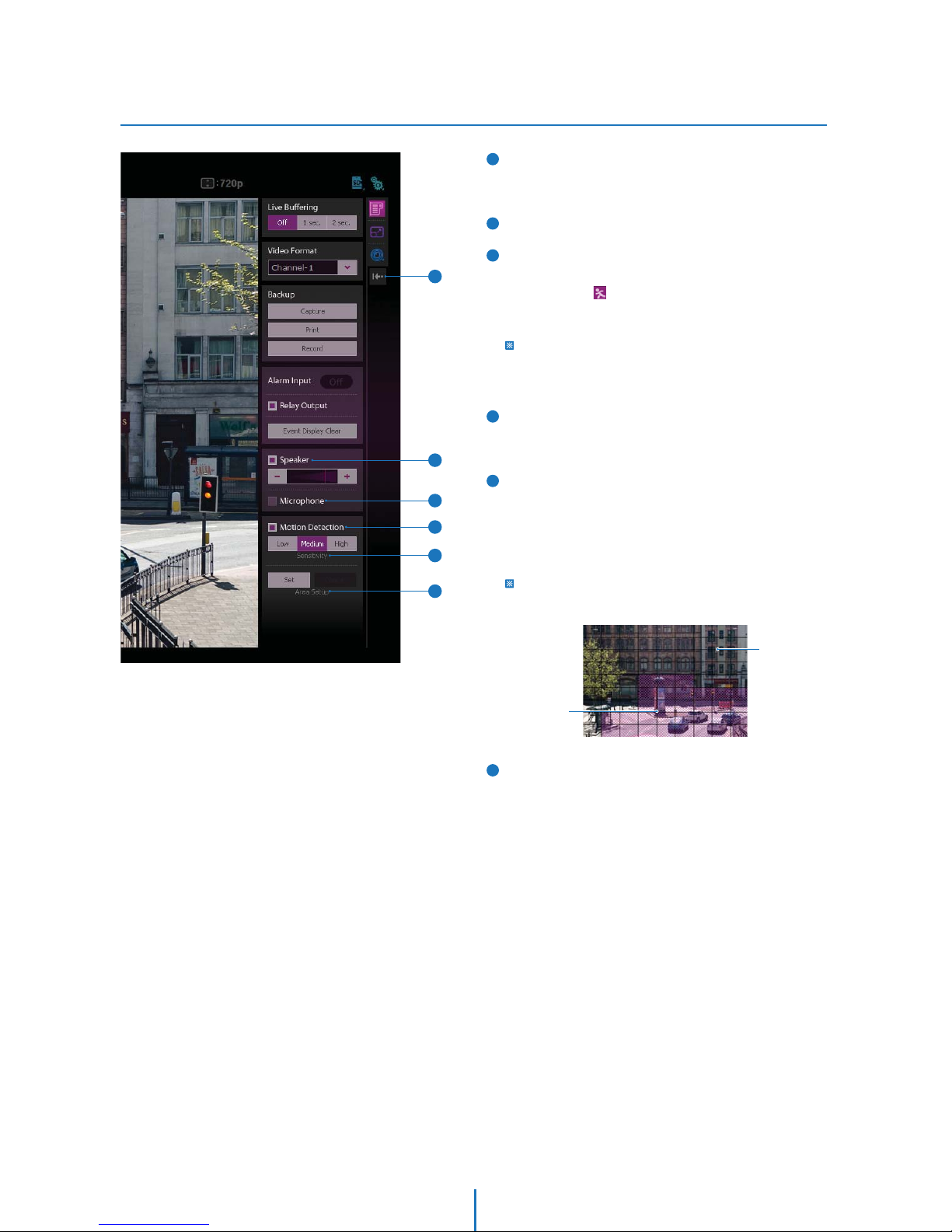
Control Tab
Web Viewer Screen -
9
11
Speaker Control. Enable/Disable Audio stream received
from the camera and Volume control of the speaker in the
computer.
Mic Control. Enable/Disable the Audio stream to the camera.
Motion Detection. Enable or Disable motion detection
function. ‘Area Setup’ below must be done in advance.
Event Alert Icon( ) appears on the screen if 'Motion
Detection' is activated. Icon will remain unless 'Event Display
Clear' button is clicked.
While the motion detection is activated, this function is
de-activated momentarily if the OSD and OSD menu is shown on
the screen. Then, it is re-activated when the OSD and OSD menu
is disappeared.
Sensitivity. Define the sensitivity of motion detection. If
High is selected, it will detect very small motion while it
becomes relatively insensitive when Low is selected.
Area Setup. Setup the target area of motion detection.
<How To Setup>
1) If ‘Set’ button is clicked, Live screen shows grids to help area setup.
2) By clicking or dragging mouse on the grids, create or erase the
masks on the main view.
3) Motion detection is effective in the masked Area.
4) Save setting by clicking ‘Save’ button.
Area Setup is possible only on the Ch No.1 in the ‘Video Format’.
If you change the video format, motion detection area will return
the setup to the default.
Hide Button. Hide all control panels extended.
Unmasked Area
No Detection
Masked Area
Detection Eective
12
13
14
10
11
10
12
13
9
14
23
Page 24
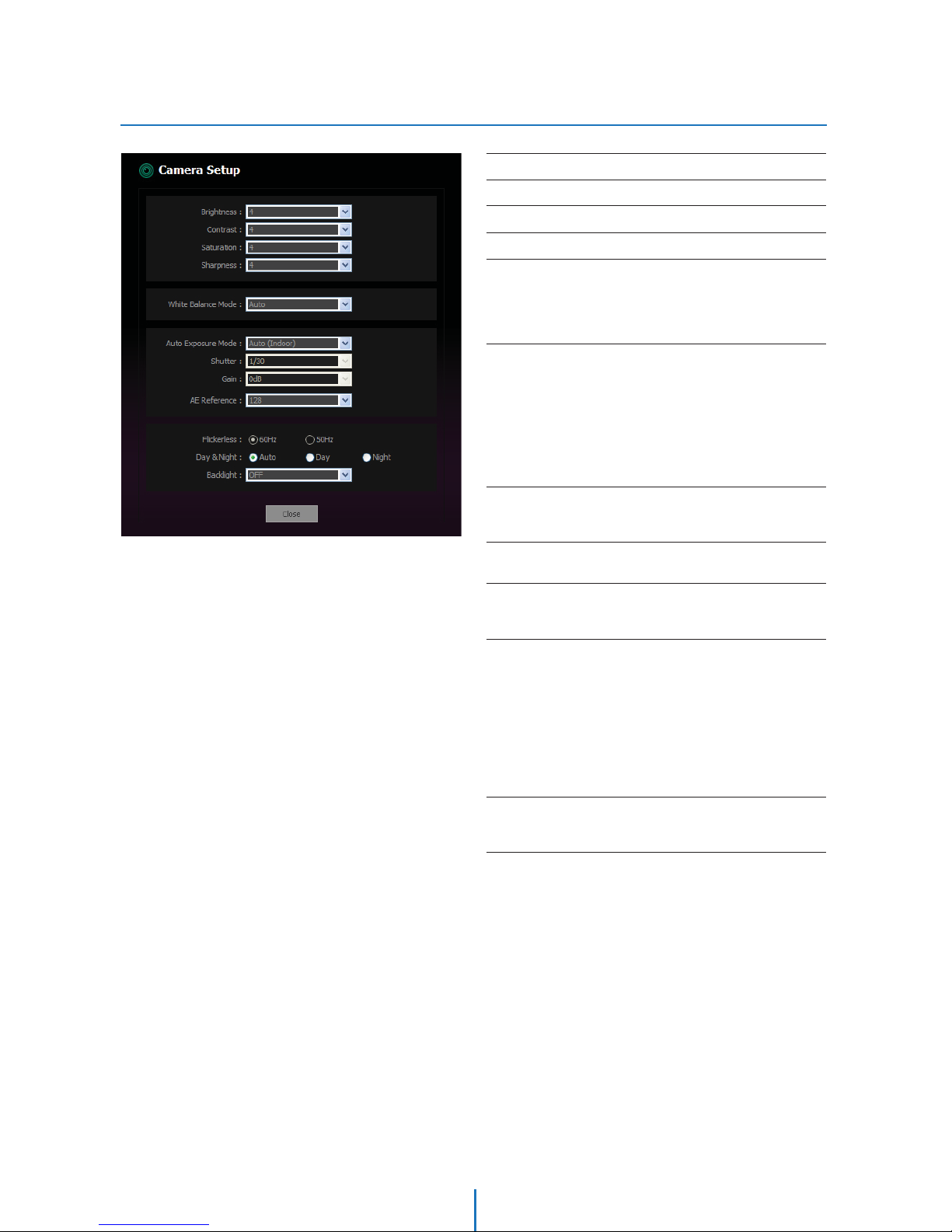
Camera Setup 1 (1M Camera Only)
Camera Setup -
Bright
Contrast
Saturation
Sharpness
White Balance Mode
Auto: The camera performs white balance automatically.
Indoor: WB will be done under the assumption of the Indoor
illumination.
Outdoor: WB will be done under the assumption of the Sun light.
Auto Exposure Mode
Auto(Indoor/Outdoor): The camera adjust the exposure under the
assumption of the sun light or Indoor illumination by itself
automatically.
Shutter Priority: The shutter speed can be selected by the user while
iris and gain are controlled by camera automatically.
Manual: Shutter speed and Gain can be adjusted by users according
to their preference.
Shutter
The slower the shutter setting, the brighter the image is. However, the
haunting can happen on the image when the object is moving fast.
Gain
The smaller number makes the daker image.
AE Reference
It is a theshold value to adjust exposure automatically when AE Mode
is Auto.
Day & Night
Day: In this mode, the IR cut filter is applied to the image sensor
all the time. Thus, the sensitivity will be reduced in the dark light
condition but the better color reproduction performance are
obtained.
Night: In this mode, the IR cut filter on the image sensor is removed
all the time. The sensitivity will be enhanced in the dark light
condition
but the image is black and white.
Auto: In this mode, the IR cut filter is removed automatically
depending on the light condition around.
Backlight
When the background is too bright or the object is too dark, the
backlight compensation will make the target object look clearer.
0 ~ 9 (10 Steps, Default: 4)
0 ~ 9 (10 Steps, Default: 4)
0 ~ 9 (10 Steps, Default: 4)
0 ~ 9 (10 Steps, Default: 4)
Auto / Indoor / Outdoor
Auto(Indoor) / Auto(Outdoor)
/ Shutter Priority / Manual
1/7.5 ~ 1/100,000 (10 Steps)
0dB ~ 24dB (17 Steps)
0 ~ 255 (256 Steps, Default: 128)
Auto / Day / Night
OFF / MIN / MID / MAX
24
Page 25
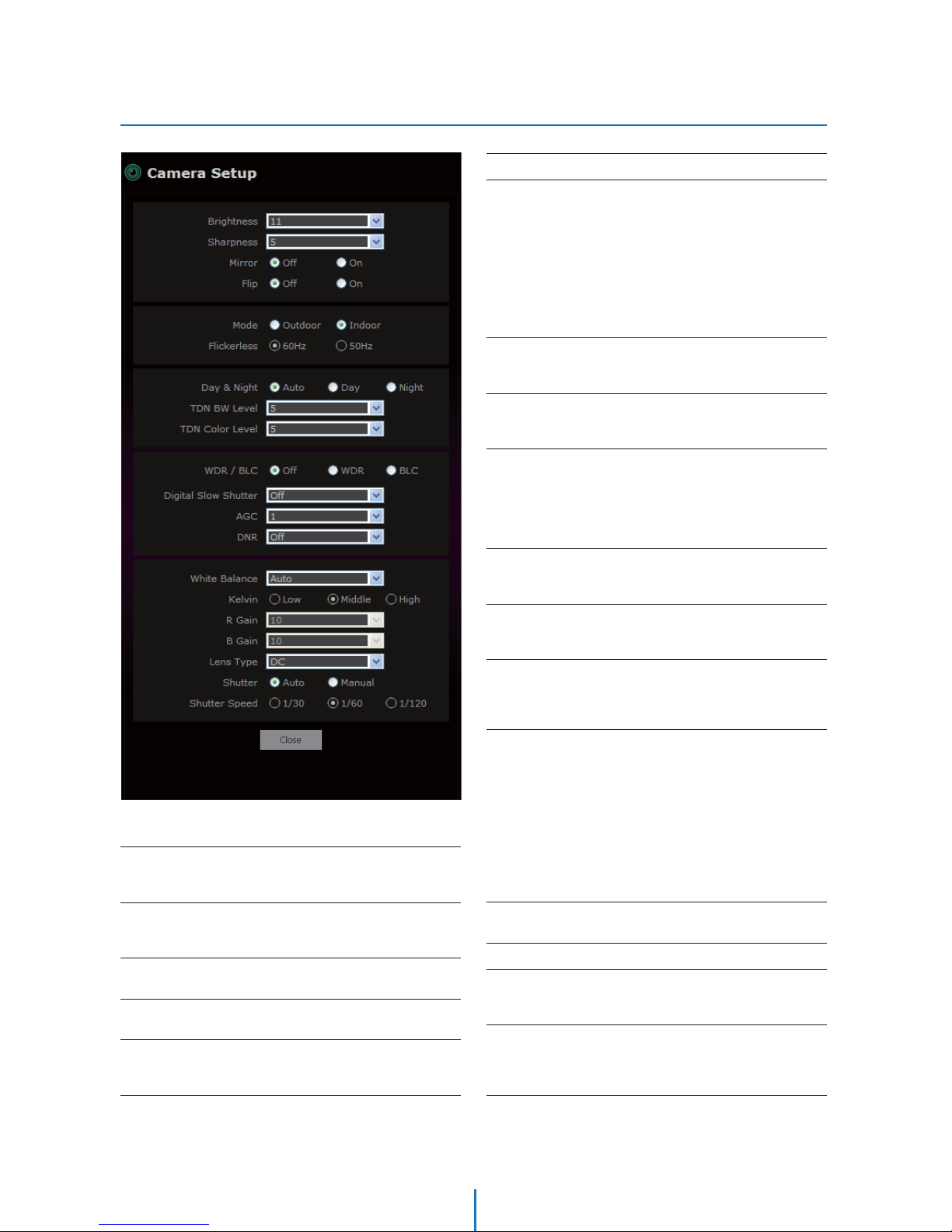
Camera Setup 2 (2M Camera Only)
Camera Setup -
Flickerless(Read Only)
Day & Night
Auto: In this mode, the IR cut filter is removed automatically
depending on the light condition around.
Day: In this mode, the IR cut filter is applied to the image sensor all
the time. Thus, the sensitivity will be reduced in the dark light
condition but the better color reproduction performance are
obtained.
Night: In this mode, the IR cut filter on the image sensor is removed
all the time. The sensitivity will be enhanced in the dark light
condition but the image is black and white.
TDN BW Level
It is a level to change Day mode into Night mode when Day & Night
mode is Auto.
TDN Color Level
It is a level to change Night mode into Day mode when Day & Night
mode is Auto.
WDR / BLC
WDR: This function is intended to provide clear live image even under
back light circumstances when there are both very bright and very
dark areas simultaneously in live video.
BLC: When the background is too bright or the object is too dark, the
backlight compensation will make the target object look clearer.
Digital Slow Shutter
The slower the shutter setting, the brighter the image is. However, the
haunting can happen on the image when the object is moving fast.
AGC
Enhances the brightness of the image by amplifying gain when the
illumination is low.
DNR
If reduces the noise caused by ‘AGC’ action. If set towards ‘HIGH’, the
noise will be reduced but the ghost effect on moving objects will be
increased.
White Balance
Auto: The color temperature is adjusted automatically between
2500K and 10000K.
Auto-L: The color temperature is adjusted automatically between
2500K and 7000K.
Auto-H: The color temperature is adjusted automatically between
4000K and 10000K.
Preset: Color temperature of moment of select to Preset is set to WB
in current environment.
Manual: The color temperature and the R/B gain level can be set up
manually.
Kelvin
This function is set to the range of color temperture to adjust the WB.
R / B Gain
Shutter
If Shutter is set to Auto, shutter speed is adjusted automatically
which refers to surrounding illumination.
Shutter Speed
If this speed is faster, the moving object can be photographed
without the ghost effect. However, pic
ture can be dark if there is no
sufficient lighting. This menu is activated when Shtter is set to Manual.
Bright
Using this control, brightness of image can be adjusted to meet your
preference.
Sharpness
Using this control, sharpness of image can be adjusted to meet your
preference.
Mirror
Reverse the video from side to side.
Flip
Reverse the video from up to down.
Mode
This function will prevent flickering screen from the natural outdoor
light or indoor light.
25
Page 26
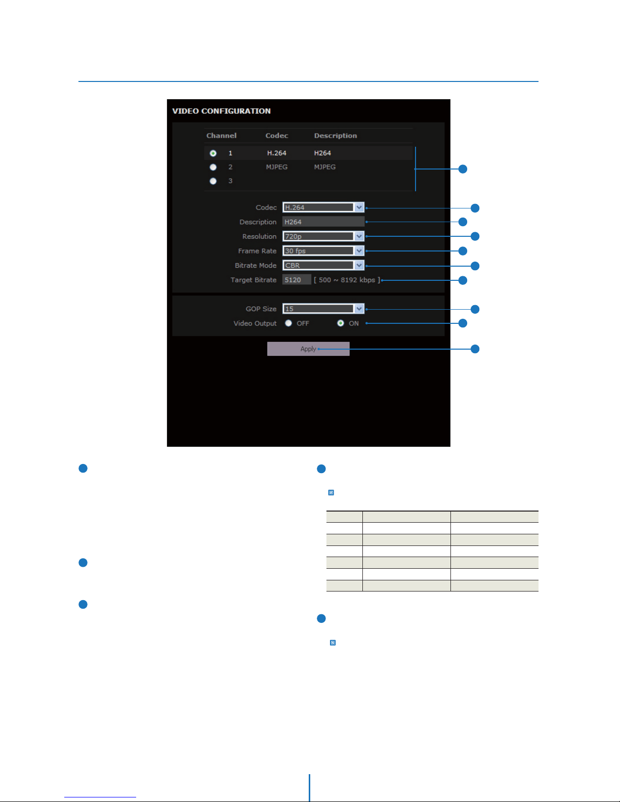
Video Setup
Setup -
Resolution
Select the video resolution.
Available resolution can be depends on the codec setup between
the channels.
<Resolution of Video Format>
3
2
4
Live Video Channel Setup
Setup the multiple codec and Video according to the
environment of installed camera. Using selected channel
on the ‘Web-Viewer > Control Tab > Video Format’.
CH No.1 and No.2 are the default CH, so they can't be
changed. However, detailed category of default codec can
be setup. CH No.3 is the user channel, and codec and
detailed category of codec can be setup.
Codec
Choose the video codec. According to the selected codec,
the subcategories can be changed automatically.
Description
Input the additional description about the selected channel.
Max. 15 alphabets are allowed(Including space). For the
description, English Alphabets, numbers and special
characters ( / ~ ` ! @ $ ^ ( ) _ - { } [ ] ; , ) can be used.
1080p/i
720p/i
D1
4CIF
CIF
QCIF
PAL
1920 x 1080
1280 x 720
720 x 576
704 x 576
352 x 288
176 x 144
1
NTSC
1920 x 1080
1280 x 720
720 x 480
704 x 480
352 x 240
176 x 120
1
2
3
4
8
7
6
5
10
9
5
Frame Rate
Select the maximum Frame Rate.
Available Frame Rate can be different although same codecs
were set up.
26
Page 27
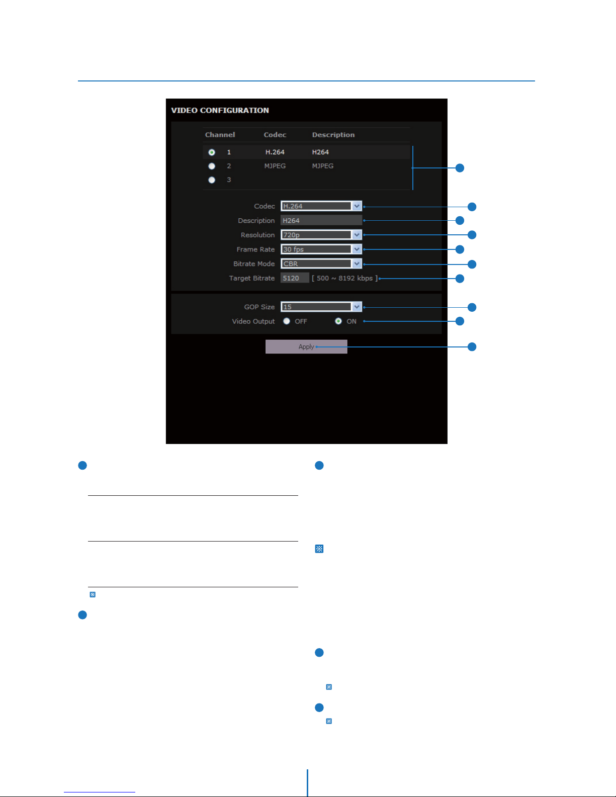
Video Setup
Setup -
6
7
CBR
To guarantee the designated constant bit rate, the quality of video
are controlled in this mode. Therefore, the quality of video is likely
to be varying when network traffic is changing.
VBR
To guarantee the designated quality, the bit rate of video stream
is changed in this mode. Therefore, the frame rate of video is likely
to be varying when network traffic is changing
Bitrate Mode
Select the bit rate control scheme of video compression
from CBR (Constant Bit Rate) or VBR (Variable Bit Rate).
This category won't be appear if you select the codec.
Target Bitrate
If Bitrate Control is set to be CBR, you can set the Target
Bitrate.
............................................................................................................
Quality
For VBR control mode, The Target Quality of video can be
setup.
8
9
10
GOP(Group of Pictures) Size
Set up the number of frames (P-frame) which contain only
changed information based on basic frame (I-frame).
Regarding videos with lots of movement, if you set GOP size
bigger, only the number of P-frames is bigger. As a result,
video resolution will be low but ‘File size’ and ‘Bit-rate can
be decreased.
GOP(Group of Pictures) Size is..
I-frame and P-frame can be created for MPEG4 and H.264
video compression. I-frame(=key-frame) means the whole
image data for one specific scene of video. P-frame is image
data which has been changed information compared to
I-frame GOP is made up of one I-frame and corresponding
several P-frames. To improve video quality, set the number
of P-frames smaller and to decrease image size, set the
number of P-frames bigger.
Video Output(Optional Function)
To check the display output status during the installation,
'On' status is required.
Recommend 'Off' status after installation.
Click ‘Apply’ to make above setting effective.
Click this button when completed setup each channels.
1
2
3
4
8
7
6
5
10
9
27
Page 28
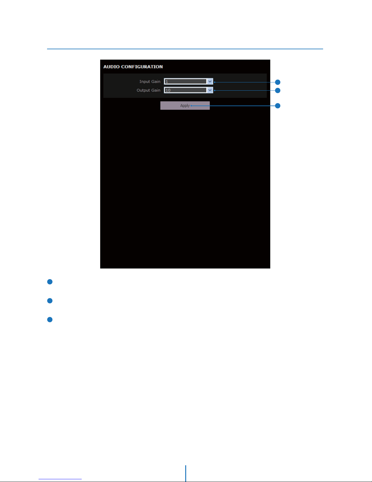
Audio Setup
Setup -
Input Gain
Adjust the input gain of audio.
Output Gain
Adjust the output gain of audio. Output gain 0 is mute.
Click ‘Apply’ to make above setting effective.
1
2
3
1
2
3
28
Page 29
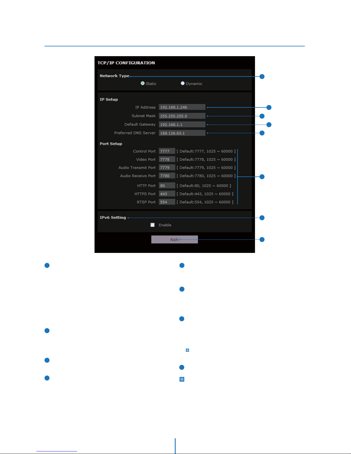
TCP/IP Setup
Setup -
Network Type
Define network IP address type from the Static Mode for the
fixed IP or the Dynamic Mode by the dynamic IP address.
If you select the Static Mode, you must fill out IP Address,
Subnet Mask, Gateway, DNS Server and all ports. If you
select the Dynamic Mode, the IP address will be allocated
automatically by DHCP equipment. If you click the Apply
button to update changes, the system will be re-booted.
In this case, you have to reconnect the camera using new IP
address.
IP Address
Define the IP address. The address is consisted of four
numbers separated by dots and the range of each number
is from 0 to 255.
Subnet Mask
Define the Subnet Mask. Format is same as the IP address.
Default Gateway
Default the Gateway IP Address. Format is same as the IP
address.
1
2
4
5
6
Preferred DNS Server
Define the DNS server IP address. Format is same as the IP
address.
Port
There are five ports in the camera providing different
services. To get those services separately, unique port
number must be assigned to each servers.
IPv6 Setting
Create the IPv6 address. If you click the Apply button after
checking the Enable check box, the system will be re-booted.
If you re-visit this screen after finishing reboot, IPv6 address
will be shown.
To use IPv6, network camera has to connect with the router for
IPv6.
Click ‘Apply’ to make above setting effective.
If the network type is dynamic, the IP address is changed in
below cases. Therefore, the IP address needs to be searched
again, and the camera needs to be reconnected in these
cases.
- When the camera power is on/off.
- After Firmware update, Default set and reboot.
7
3
8
1
2
3
4
8
6
5
7
29
Page 30
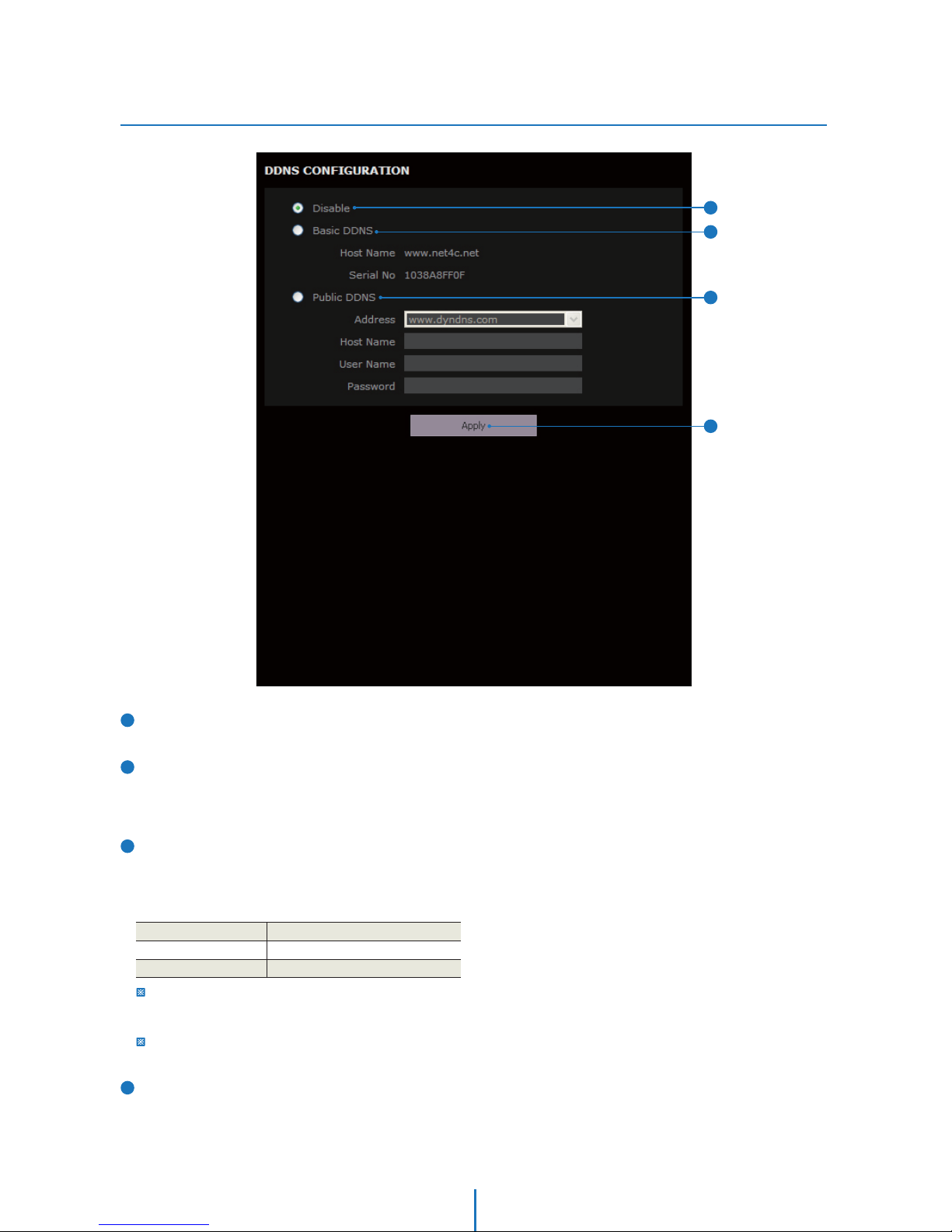
DDNS Setup
Setup -
DDNS Disable
If it is selected, DDNS service does not work.
Basic DDNS
Please register the camera in net4c site so as to use net4c
DDNS. Insert the serial number shown on the screen in the
serial entry field.
Public DDNS
To use public DDNS service, select a site address listed in the
list. After filling out the Host Name of the site, the setup is
completed by entering User Name and Password registered
in that DDNS site.
1
2
3
DDNS Provider Site Address
DynDNS
No-IP
www.dyndns.com
www.no-ip.com
If you setup DDNS properly, the IP address of your camera will be
updated automatically whenever IP address is changed or system
is rebooted.
If IP updating to DDNS site is failed, camera will keep retrying in
1min. interval.
Click ‘Apply’ to make above setting effective.
4
1
2
3
4
30
Page 31
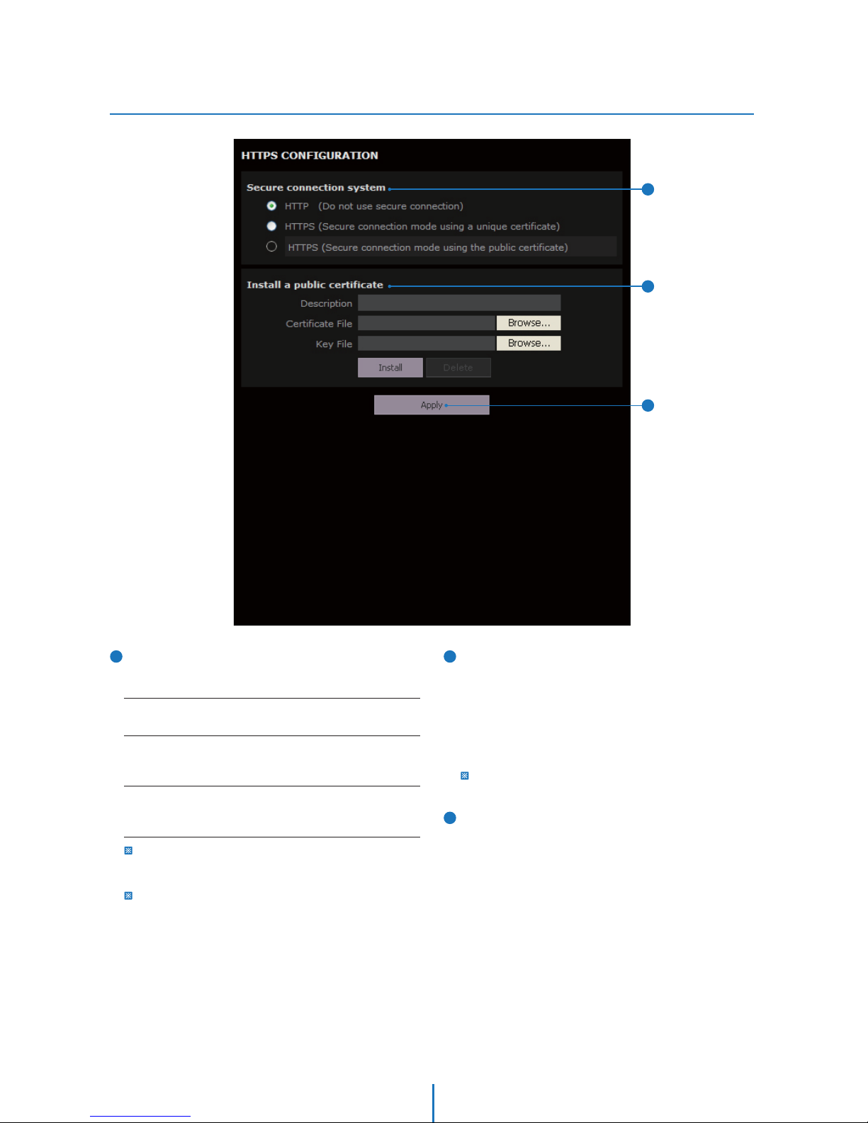
Secure Connection System
Secure Connection System chooses a method of security
connection.
HTTPS (Secure connection mode using the public certificate)
method can be selected only if a certificate has been already
installed.
When HTTPS mode is chosen, input https://<IP Address> to
connect to the camera.
1
2
3
Install a public certificate
A certificate issued by Certificate Authority can be installed
to the camera and the installed certificate can be deleted.
<How to install or delete the certificate>
1) Input the description(name) of a certificate.
2) Click ‘Install’ button after selecting the certificate files and
key file to be installed.
3) To remove the certificate files, click ‘Delete’ button.
While using HTTPS (Secure connection mode using the public
certificate) method, the certificate cannot be deleted.
Click ‘Apply’ to make above setting effective.
HTTP
HTTP mode does not use a security connection method.
HTTPS (Secure connection mode using a unique certicate)
This mode is a security connection method which uses the
(temporary) certicate in the camera.
HTTPS (Secure connection mode using the public certicate)
This mode is a security connection method which uses a certicate
issued by certicate authority.
HTTPS Setup
Setup -
2
3
1
31
Page 32
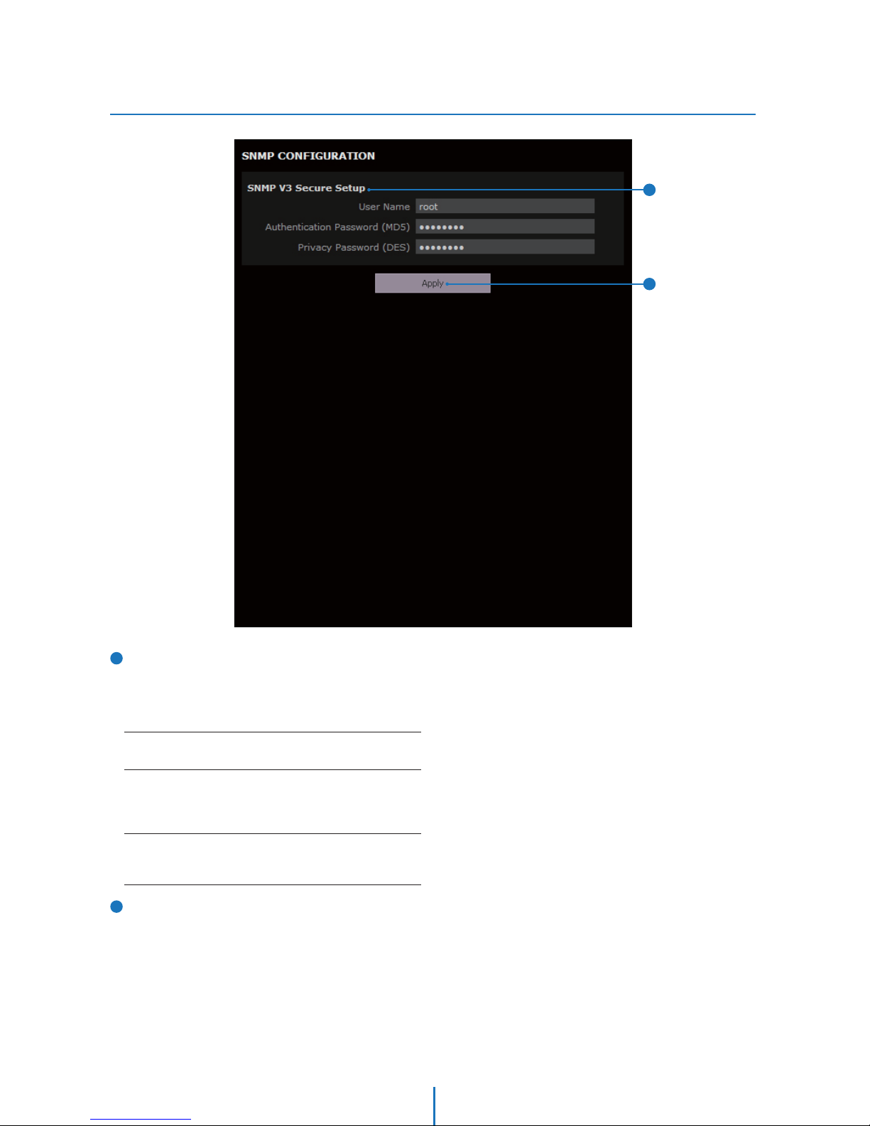
SNMP Setup
Setup -
SNMP V3 Secure Setup
- The information of camera system can be known and
configured with SNMP.
- The changes for configuration use version 3 and username
and password should be certified at that time.
1
2
Click ‘Apply’ to make above setting effective.
Username
Username is the information of user account for user authentication.
Authentication Password(MD5)
The Authentication Password (MD5) is an encryption for
authentication and they are at least 8 digits and up to 30 digits
allowed.
Privacy Password(DES)
Information protection password is a private encryption and they
are at least 8 digits and up to 30 digits allowed.
1
2
32
Page 33
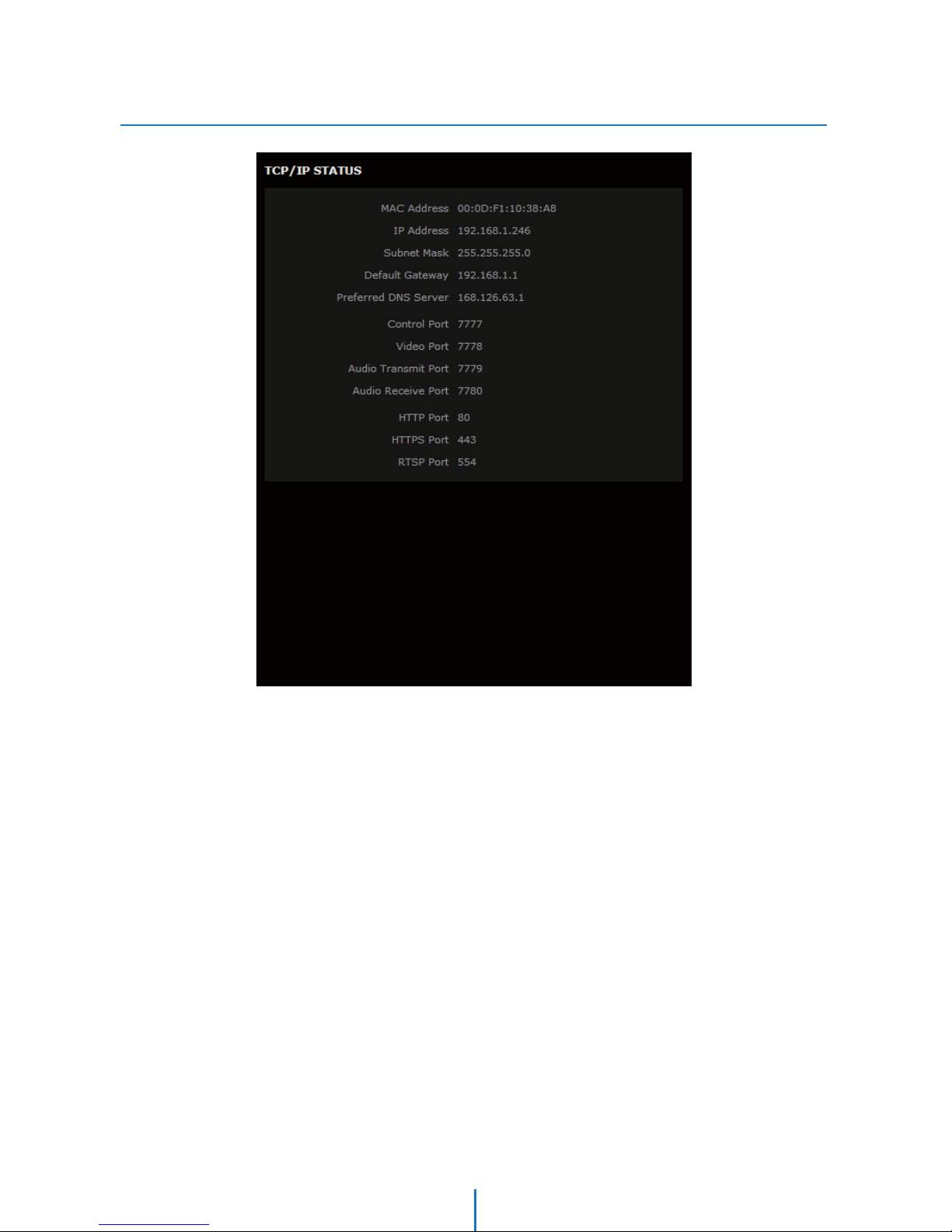
Status
Setup -
This menu will show you all the information of Network setting in the camera. However, you cannot change those here.
33
Page 34
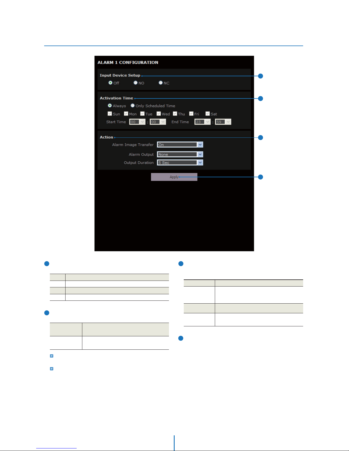
Alarm Input Setup
Setup -
Input Device Setup
Select input device type from OFF / N.O. / N.C.
Activation Time
Select activation time from Always / Only Scheduled Time.
Operation
O
NO
NC
Ignore this Input sensor.
The contact is normally open and closed when activated.
The contact is normally closed and open when activated.
Always
Only
Scheduled Time
An alarm event is activated whenever sensor
Input is detected.
An alarm event is activated only when sensor
input is detected during the scheduled time.
To setup the schedule, you need to define Start time and End time
followed by selecting Days.
If End time is earlier than Start time, End time is regarded as next
day.
Ex) Assume you select Tue. If you set Start time as 16:00 and End
Time as 09:00, Alarm Input will work from 4:00pm Tue to
9:00am Wed.
2
3
4
1
2
DescriptionAction
Output
Duration
Alarm Image
Transfer
Alarm Output Activate alarm out (relay).
Select time duration to maintain output.
Turn ON / OFF Image Transfer. Send image via
E-mail or FTP server. (For more detail see
Transfer Setup in this chapter)
4
Action
Define a counter action from Alarm Output / Alarm Image
Transfer / Camera Action when Alarm Input is detected.
Click ‘Apply’ to make above setting effective.
3
1
34
Page 35
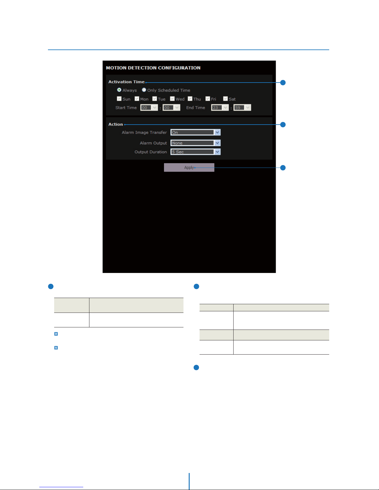
Motion Detection Setup
Setup -
Activation Time
Select activation time from Always / Only Scheduled Time.
DescriptionAction
Output
Duration
Alarm Image
Transfer
Alarm Output Activate alarm out (relay).
Select time duration to maintain output.
Turn ON / OFF Image Transfer. Send image via
E-mail or FTP server. (For more detail see
Transfer Setup in this chapter)
1
2
Action
Define a counter action from Alarm Output / Alarm Image
transfer when motion is detected.
Always
Only
Scheduled Time
An alarm is activated whenever motion is
detected.
An alarm event is activated only when motion
is detected during the scheduled time.
To setup schedule, you need to define Start time and End time
followed by selecting Days.
If End time is earlier than Start time, End time is regarded as next
day.
Ex) Assume you select Tue. If you set Start time as 16:00 and End
Time as 09:00, Alarm Input will work from 4:00pm Tue to
9:00 am Wed.
3
Click ‘Apply’ to make above setting effective.
1
2
3
35
Page 36
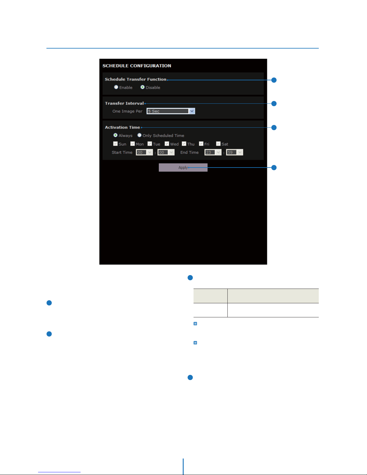
Schedule Setup
Setup -
Enable / Disable
Set Schedule function to be enabled or disabled. Schedule
function enables to transfer series of still images in a time
interval specified.
Transfer Interval
Define time interval of image transfer.
Schedule function enables to transfer series of still images in
a time interval specified via E-mail or FTP. (For more detail,
see ‘Transfer Setup’ in this chapter)
1
2
Activation Time
Select activation time from Always / Only Scheduled Time.
3
Always
Only
Scheduled Time
Transfer image at all times.
Transfer image during the scheduled time.
To setup ‘Only Scheduled Time’, you need to define Start time and
End time followed by selecting Days. The setup schedule is
repeated every week.
If End time is earlier than Start time, End time is regarded as next
day.
Ex) Assume you select Tue. If you set Start time as 16:00 and End
Time as 09:00, Alarm Input will work from 4:00pm Tue to 9:00am
Wed.
4
Click ‘Apply’ to make above setting effective.
1
2
4
3
36
Page 37
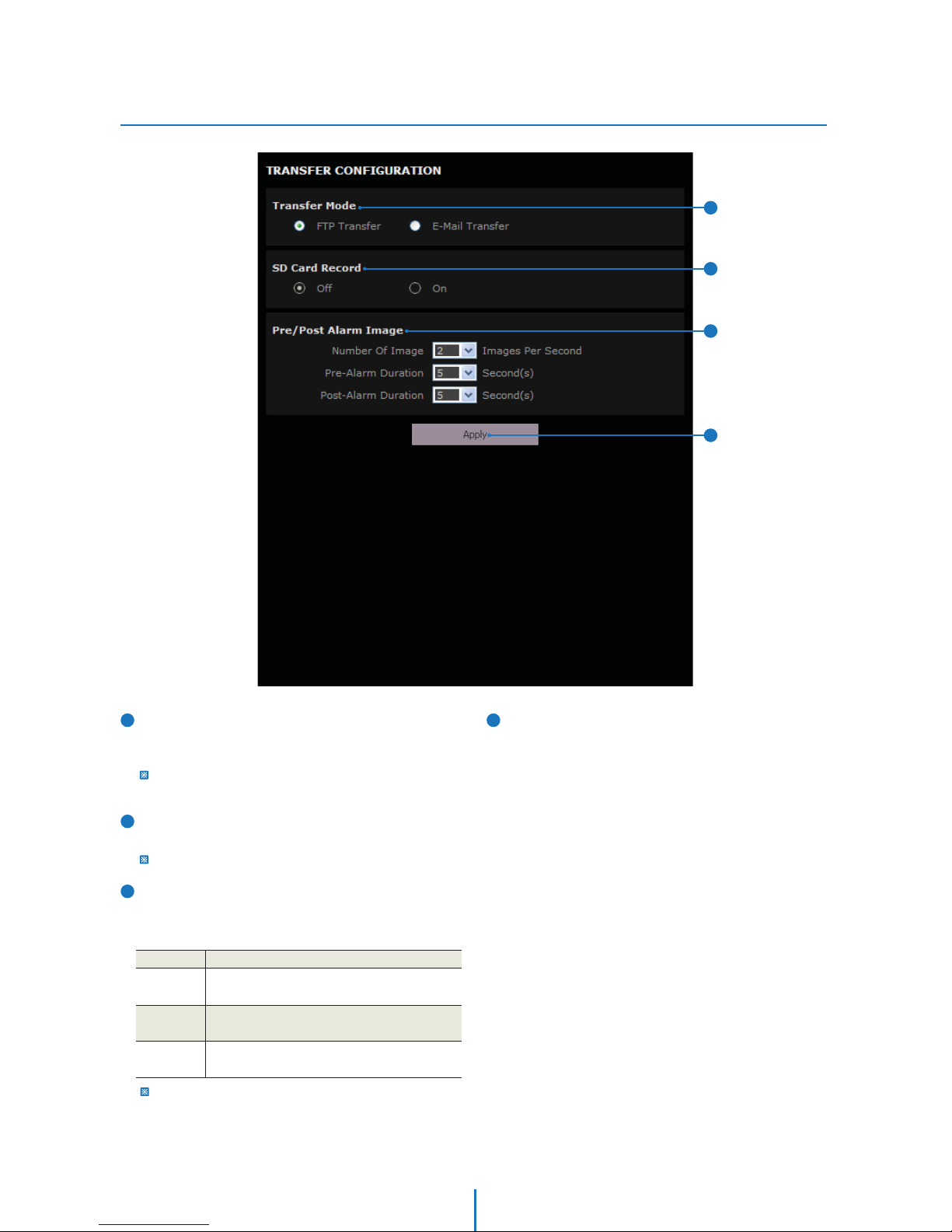
Transfer Setup
Setup -
1
Range of Pre/Post alarm duration can be changed according to
Number of image setting.
Click ‘Apply’ to make above setting effective.
4
3
2
Transfer Mode
Image Transfer method is selected from FTP and
E-Mail (SMTP).
To use image transfer, FTP and SMTP in the next sections must
be configured properly.
SD Card Record
If it is set to On, the image is saved into the SD card as well.
It will setup OFF automatically when SD card doesn't applied.
The SD card setting can be configured on the SD CARD section.
Pre/Post Alarm Image
Image Transfer due to event is configured by setting Image
transfer rate and Pre/Post alarm duration.
Number
of Image
Pre-alarm
Duration
Post-alarm
Duration
Dene Number of image transferred per second.
Descriptions
Define duration of image transfer before an event.
Define duration of image transfer after an event.
1
2
4
3
37
Page 38
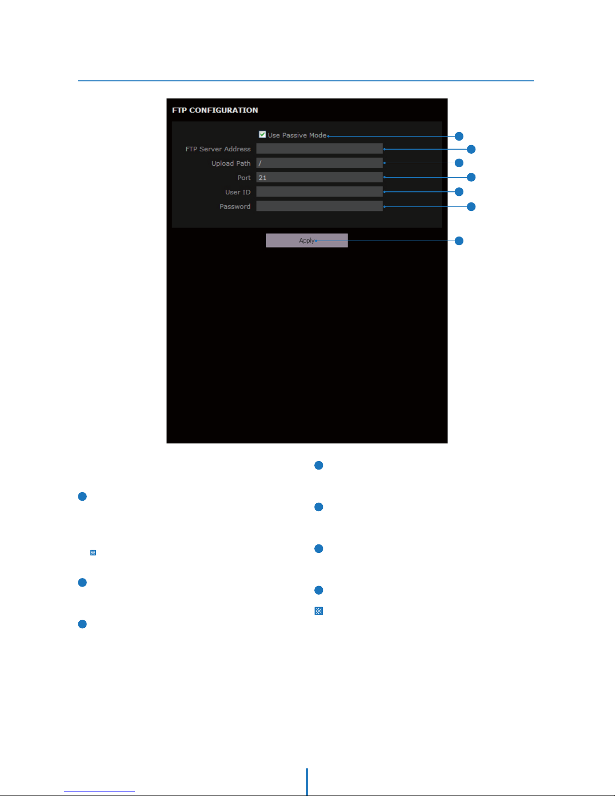
FTP Setup
Setup -
Use Passive Mode
Check it to use Passive mode for FTP transfer. If it is not check,
the transfer becomes Active Mode. However, if you select
active mode, it is possible that there might be problems due
to the firewall. Consult with your network manager.
In Active mode, the FTP transfer might not work due to the
firewall. In this case, ask to the network administrator.
FTP Server Address
Define FTP Server IP Address. If IP Address form is incorrect,
a Message box will be shown to try again.
Upload Path
Define a path in FTP server to store video. For the path name,
English Alphabets, numbers and special characters
aC
#AB^`>@can be used.
1
2
4
5
6
Port
Define the FTP Server Port. If Port is not appropriate, it is
impossible to access to FTP Server.
User ID
Define User ID to access to the FTP Server. Fill out the correct
User ID registered in the FTP Server.
Password
Define Password to access to the FTP Server. Fill out the
correct Password registered in the FTP Server.
Click ‘Apply’ to make above setting effective.
Refer the above screen image for the example.
3
7
To transfer/save the image to the relevant sites through FTP,
then FTP needs to be setup.
1
2
3
4
6
5
7
38
Page 39
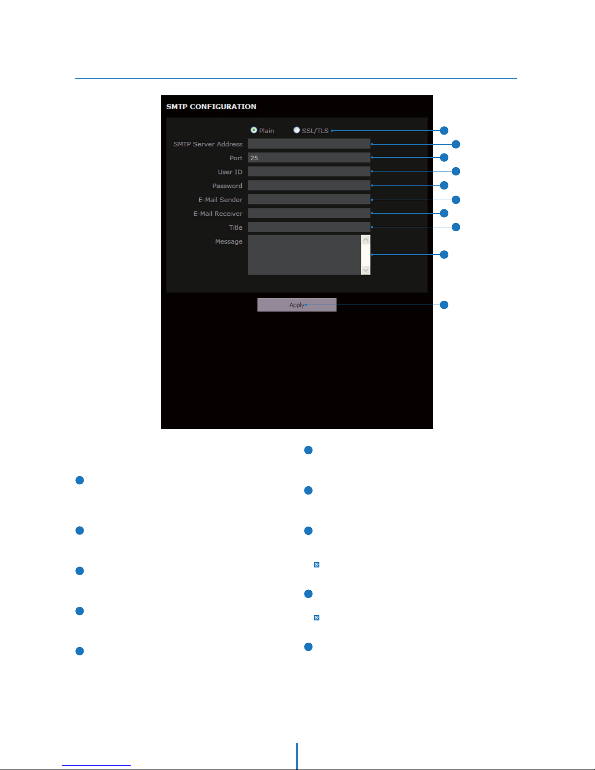
SMTP Setup
Setup -
E-Mail Sender
Define the e-mail address of E-Mail Sender. It will be
displayed as the sender when the camera sends an E-mail.
E-Mail Receiver
Define the e-mail address of E-Mail Receiver. It will be
displayed as the Receiver when the camera sends an E-mail.
Title
Define the title of the E-Mail when the camera sends an
E-mail.
The title of the Email is limited to 40 characters including the
spaces.
Message
Define the contents of E-Mail when camera sends an E-mail.
The message of the Email is limited to 40 characters including
the spaces.
Click ‘Apply’ to make above setting effective.
Plain, SSL/TLS
Select Security mode of SMTP from Plain or SSL/TLS. After
checking account setup of your SMTP Server, you may
select one.
SMTP Server Address
Define the SMTP Server Address. If the IP Address form is
incorrect, a Message box will be shown to try again.
Port
Define the Port used in the Plain or SSL/TLS security mode
in the above.
User ID
Define the User ID to access to SMTP Server. Fill out the
correct User ID registered in the SMTP Server.
Password
Define the Password to access to SMTP Server. Fill out the
correct Password registered in the SMTP Server.
1
2
4
5
3
6
7
8
9
10
To send/save the image to the relevant sites by Email, SMTP
needs to be setup.
2
1
3
4
6
5
7
8
9
10
39
Page 40
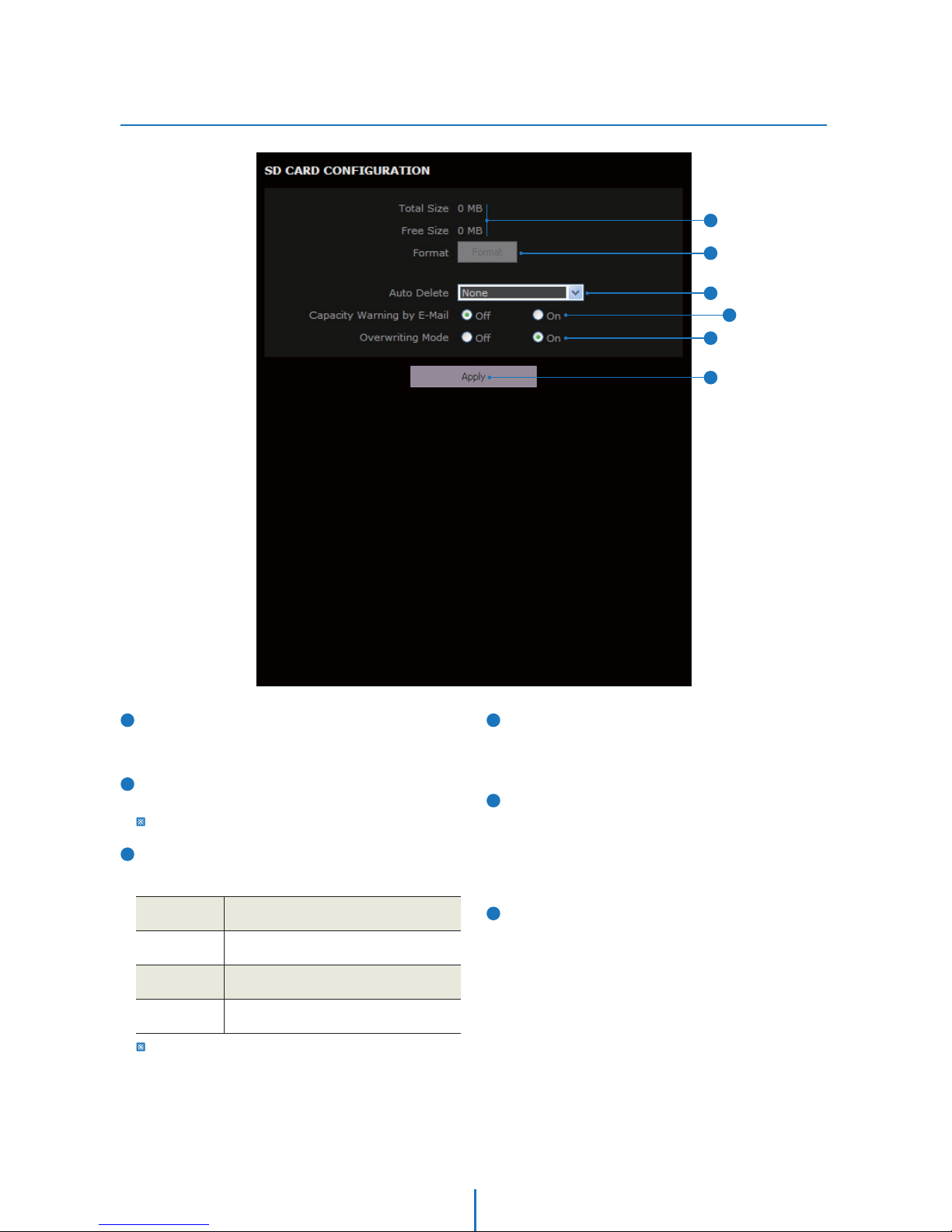
SD CARD Setup
Setup -
Total size / Free size
Total capacity of SD card and the remainder of it are
displayed.
Format
Delete the all contents that stored in SD card.
If the SD card doesn't applied, ‘Format’ button will be deactivated.
Auto Delete
Select the period for Auto delete. The image data stored
before period will be deleted automatically.
It is noted that this function will be executed everyday to delete
data before designated period.
1
2
4
5
6
3
Capacity Warning E-mail
If it is set ON and remained space of SD card reach to less
than 8MB, a warning e-mail will be sent to the e-mail
account set in SMTP menu.
Overwriting Mode
If it is set ON and remained space of SD card reach to less
than 8MB, new data will start to be overwritten on the
oldest data. However, if it is set OFF and remained space of
SD card reach to less than 8MB, image recording will be
stopped.
Click ‘Apply’ to make above setting effective.
1 Year
Delete all stored image older than 1 Year
from 00:00 today.
Delete all stored image older than 1 Month
from 00:00 today.
Delete all stored image older than 1 week
from 00:00 today.
Do not use ‘Auto Delete’.NONE
1 Week
1 Month
1
2
3
4
6
5
40
Page 41
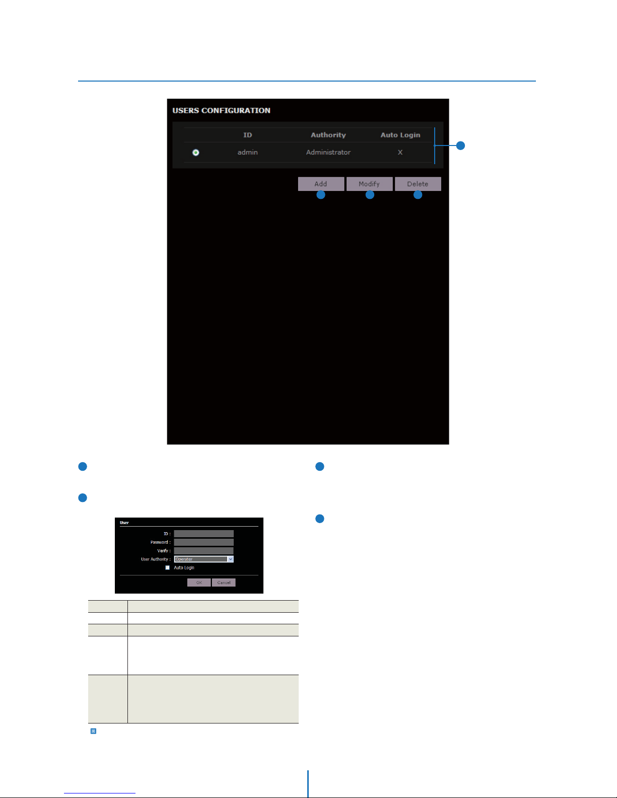
Users Setup
Setup -
Users
List all the user accounts for authentication.
Add
Register a new user
3
1
2
4
Modify
Modify the information of the user accounts registered.
For admin account, only Password and Auto Login function
can be modified.
Delete
Delete the selected user account. Admin account cannot
be deleted.
Auto Login If you check the auto login for an account, this account
becomes the public account. From the next login,
everybody can access the camera using this account
without
authentication. Only one account can have
the Auto Login.
User Level Select Operator or Viewer.
t7JFXFS : Only monitoring is allowed.
t0QFSBUPS :
Most of the functions are allowed
except ‘Setup’.
t"ENJOJTUSBUPS"MMGVODUJPOTBSFBMMPXFE
Verify Enter the user Password again for verication.
Password Enter the user Password.
ID Enter a new user ID except Admin since it exists.
The ID and Password are limited to 10 characters.
2
3
4
1
41
Page 42
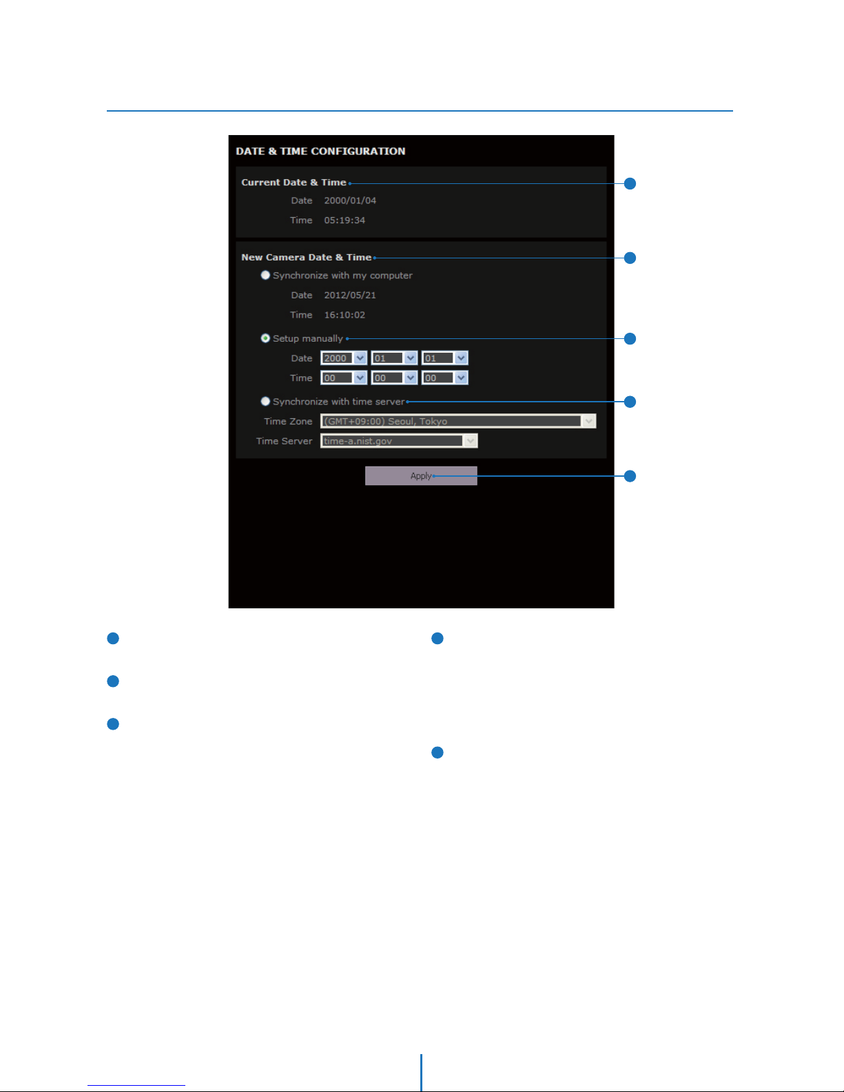
Date/Time Setup
Setup -
Current Date & Time
Shows the current date and time setting in the Camera.
Synchronize with my computer
Set the date/time using those of PC currently connected.
Setup manually
Set the date/time by typing manually.
1
2
4
Synchronize with the time server
In this mode, date/time is automatically updated using the
Time Server selected. After selecting the Time Zone
properly, Time Server must be selected. However, if you
want to assign a time server not in the list, select Manual.
Once synchronization is configured successfully, the time
and date will be updated every 1 hour automatically.
Click ‘Apply’ to make above setting effective.
3
5
2
1
3
4
5
42
Page 43
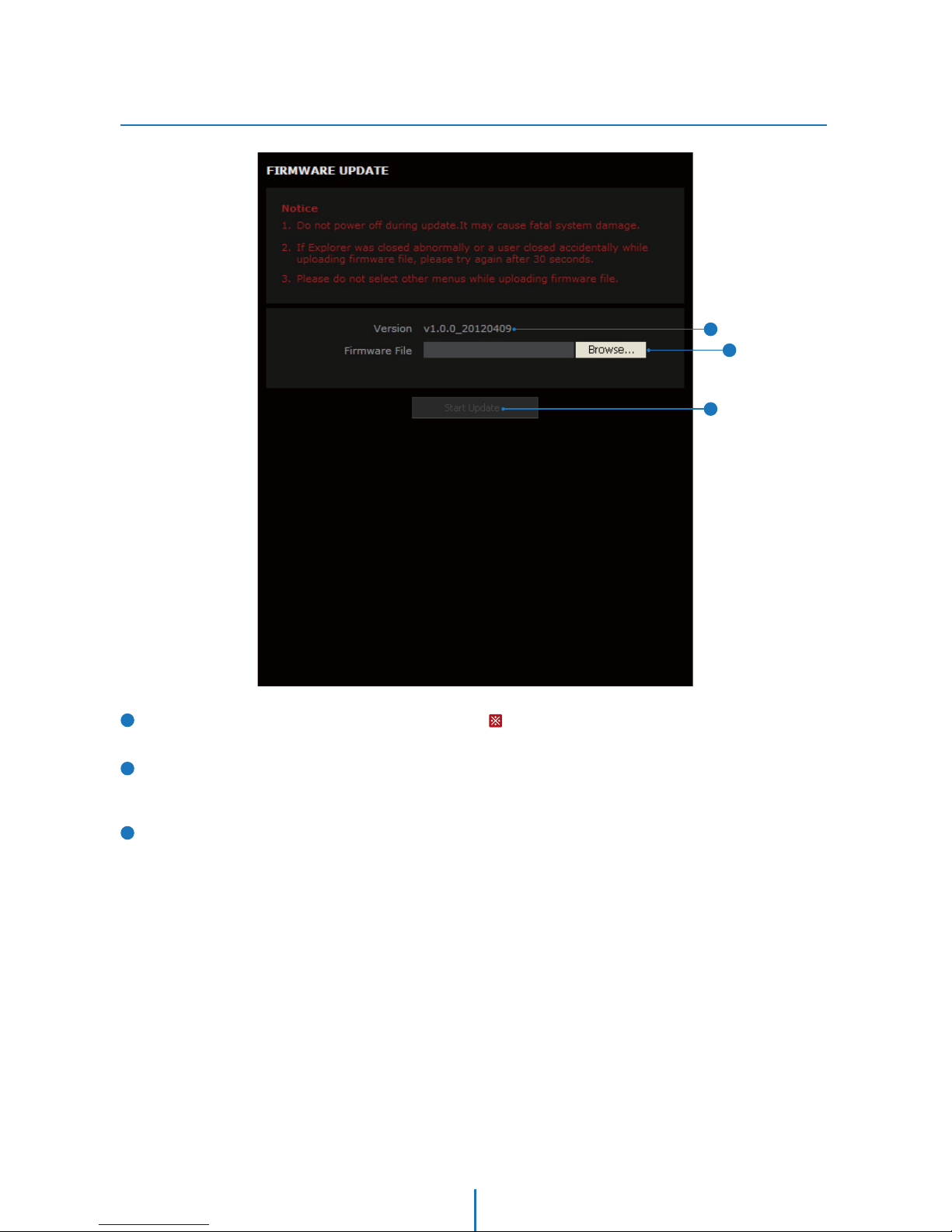
Firmware Update
Setup -
Firmware Version
It shows the current Firmware Version in the system.
Firmware Filename
Designate the Firmware file name in your computer by
clicking [Browse…] button.
Start Update
Click this button to start update. Progress of uploading will
be displayed using Progress Bar. If you assign the wrong file
name, an error massage will be shown.
3
1
2
Warning:
1. Do not turn off the power of camera during the Firmware
update. Otherwise, the system can be stuck to be unstable.
If updating is finished, the system will be rebooted
automatically.
2. Please make sure to check the ‘Notice’ shown on screen.
If firmware update is completed, the camera will reboot
automatically and ‘Setup window’ will be closed
2
1
3
43
Page 44
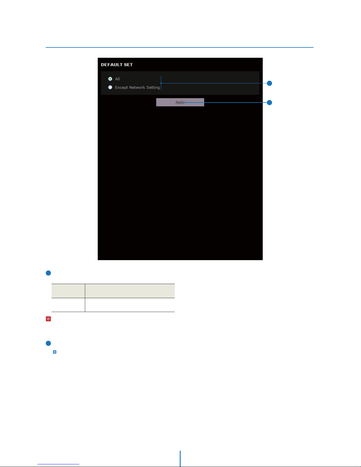
Default Set
Setup -
Reset to the Factory Defaults
Return the setup to the Factory Default.
1
All
Except
Network Settings
Reset all Settings to the Factory Defaults.
Except Network related settings, reset all
others to the Factory Defaults.
Warning:
If you click ‘Apply’, you will lose all setting data. If needed,
please, make a note for further installation.
2
Click ‘Apply’ to make above setting effective.
It takes approximated 4 minutes after clicking ‘Apply’ for the
Default Set.
2
1
44
Page 45
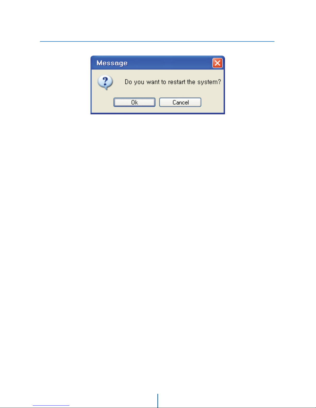
Restart
Setup -
If you click the ‘RESTART’ menu, a message box will be shown to confirm. Click the ‘Ok’ button to restart.
45
Page 46
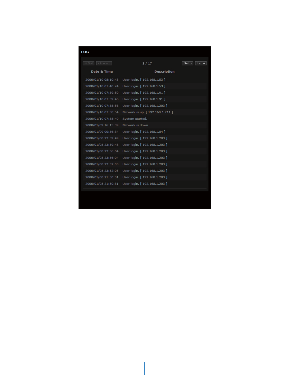
Log
Setup -
System Start, Network Connection Status(Including IP Address), Changing System Time, Changing Video Setup, Network
Setup and Event(Alarm / Motion) Alert will be recorded.
1000 PCS of Log can be stored and the recorded data won't be deleted.
46
Page 47
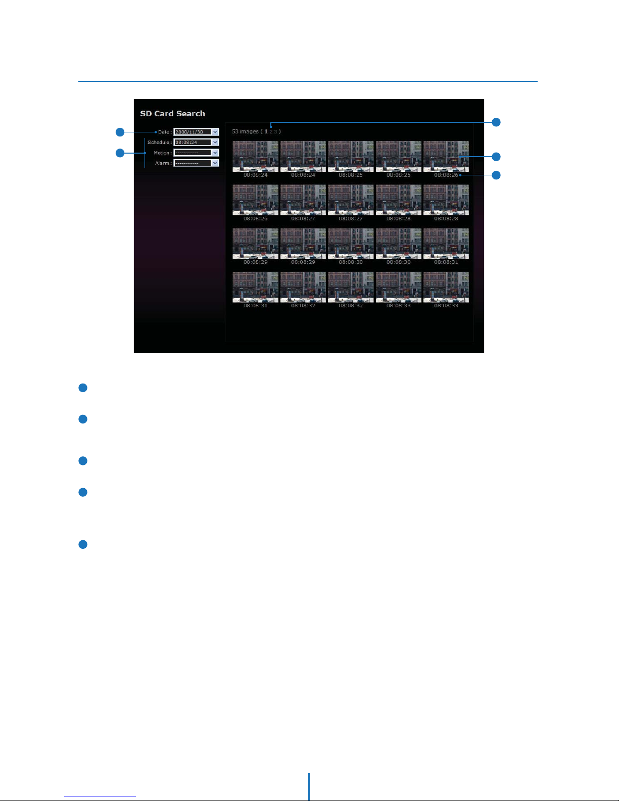
Search
SD Card Search -
3
5
4
1
2
1
2
3
4
5
Date of stored image
Choosing the date to nd the stored events.
Stored Events(Schedule / Motion / Alarm)
The interval of stored time and number of stored images in
the Event Setup can be dierent.
Page No. of searched Images
The latest page will be loaded at the head.
Stored Images
Image will be stored by value at CH No. 2 in ‘Setup>Video
conguration’. By clicking the image, see the image on the
larger screen.
Stored Time of Images
The interval of stored image can be setup depending on the
each Events.
47
Page 48
A : Current TCP/IP Settings
Appendix
Under the ‘General’ tab of the
TCP/IP Properties you will see
your IP address information.
Start
Right-click
Local Area Connection
Properties
Select the TCP/IP
in General Tab
Click Properties
Control Panel
Network and Dial-up
Connection or
Network Connection
Note the settings under the IP
Address, DNS Conguration,
and Gateway tabs
Under the ‘General’ tab of the
TCP/IP Properties you will see
your IP address information.
Start
Setting
Control Panel
Network
Conguration Tab
Select the TCP/IP
10/100 Protocol
Click Properties
Start
Network and
sharing center
Manage network
connections
Properties
Select either
Internet Protocol
Ver.4 (TCP/IPv4)
or Internet Protocol
Ver.6 (TCP/IPv4)
Click Properties
Control Panel
If your IP settings are obtained automatically, you could use the MS-DOS prompt (or Command Prompt) to determine your IP address.
For information on how to do this, please read the FAQ.
2. Windows 2000 or XP Users1. Windows 98 / ME Users 3. Windows Vista or 7 Users
48
Page 49
B : Changing IP address and subnet mask
Appendix -
Select 'Use the following IP
address'
Select 'Use the following IP
address'
2. Windows 2000 or XP Users
Start
Right-click
Local Area Connection
Properties
Select the TCP/IP
in General Tab
Click Properties
Control Panel
Network and Dial-up
Connection or
Network Connection
1. Windows 98 / ME Users 3. Windows Vista or 7 Users
Start
Setting
Control Panel
Network
Conguration Tab
Select the TCP/IP
10/100 Protocol
Click Properties
Start
Network and
sharing center
Manage network
connections
Properties
Select either
Internet Protocol
Ver.4 (TCP/IPv4)
or Internet Protocol
Ver.6 (TCP/IPv4)
Click Properties
Control Panel
Select 'Use the following IP
address' and change the IP
address and Subnet Mask.
49
Page 50
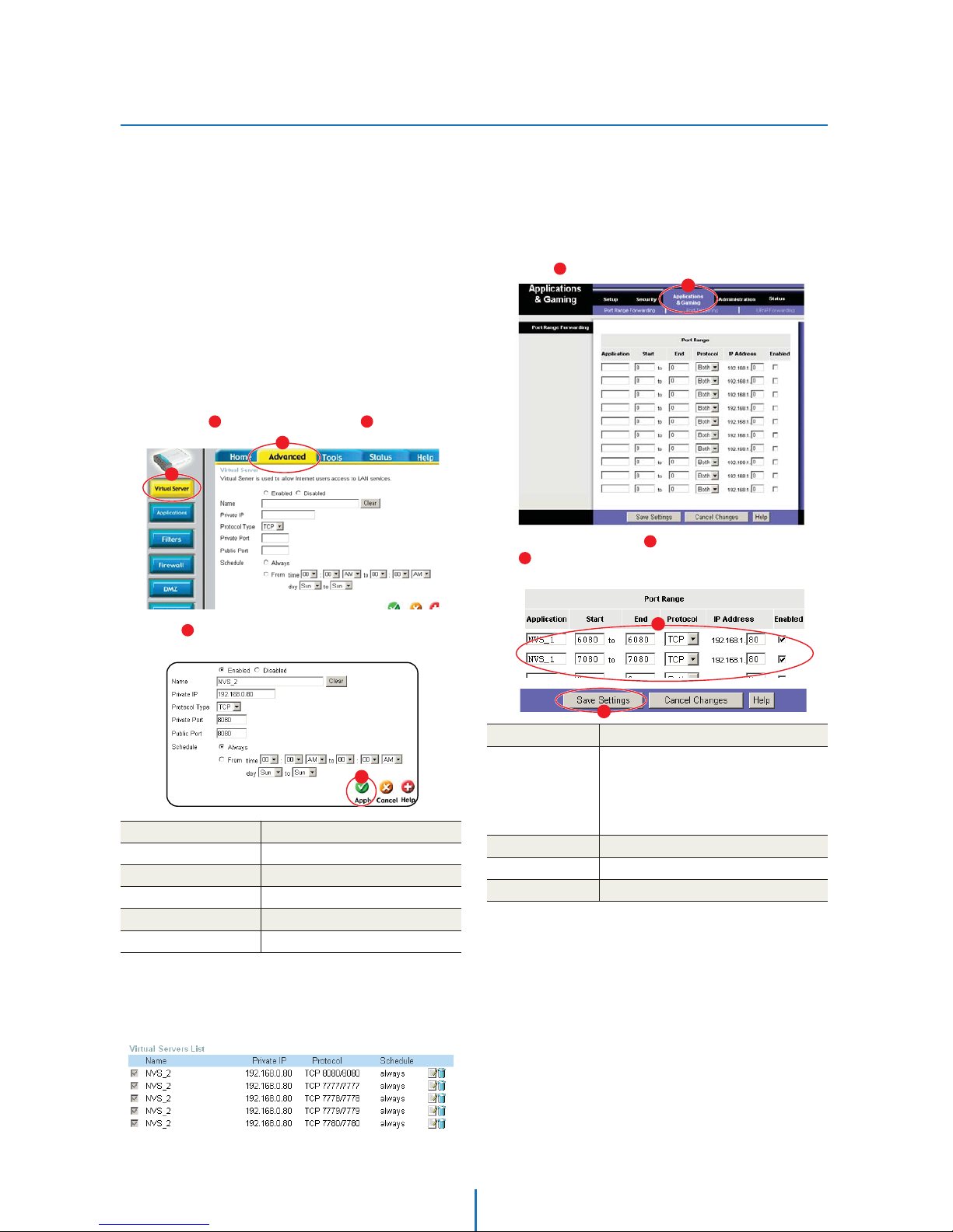
C : Port Forwarding
Appendix -
After assigning the IP Camera a web server
port and video server port you must use Port
Forwarding. (for cases A, B)
Please consult your router’s user guide on how
to correctly configure Port Forwarding.
For your convenience, we have provided two
example configurations.
For D-Link DI-604 broadband routers:
1) Open a web browser and type http://192.168.0.1 into your
Address bar. (the default IP address to access the router)
2) You will have to supply your User Name and Password to
log onto the router. Default from factory.
(User Name: admin Password: [leave blank])
3) Select the “ Advanced” tab and click " Virtual Server"
menu.
4) Click " Apply" button after inputting proper values.
The example is as below
1.
For Linksys BEFSR41 Cable/DSL routers:
1) Open a web browser and type http://192.168.1.1 into you
Address bar. (the default IP address to access the router)
2) You will have to supply your User Name and Password to
log onto the router. Default from factory
(User Name:[leave blank] Password: admin)
3) Select “ Applications & Gaming” from the menu bar.
4) Input port numbers in " Port Range" as below and click
“ Save Setting” button. Both of Web Server Port and Video
Server Port should be added. The example is as below.
2.
Enabled / Disabled
Name
Protocol Type
Private Port / Public Port
Schedule
Select “Enabled”.
Input IVS name.
Input IVS address.
Select “TCP”.
Input IVS Web Server Port.
Select “Always”
Private IP
Enabled / Disabled
Start / End
Protocol
IP Address
Enabled
Input IP Camera name.
Input IP Camera Web Server Port and Video
Server Port.
Start should be same as End.
Both of Web Server Port and Video Server
Port should be added.
Select “TCP” in Protocol option.
Input IP Camera IP Address.
Check the square.
1
3
2
4
5
6
1
2
3
5) If 'Setting Saved' shows, click [Continue] button.
6) With the same method as above, add Video Server Port.
7) The Web Server Port, Video Server Port and 2 Audio Ports
shows in "Virtual Server List" as below.
4
5
6
50
Page 51
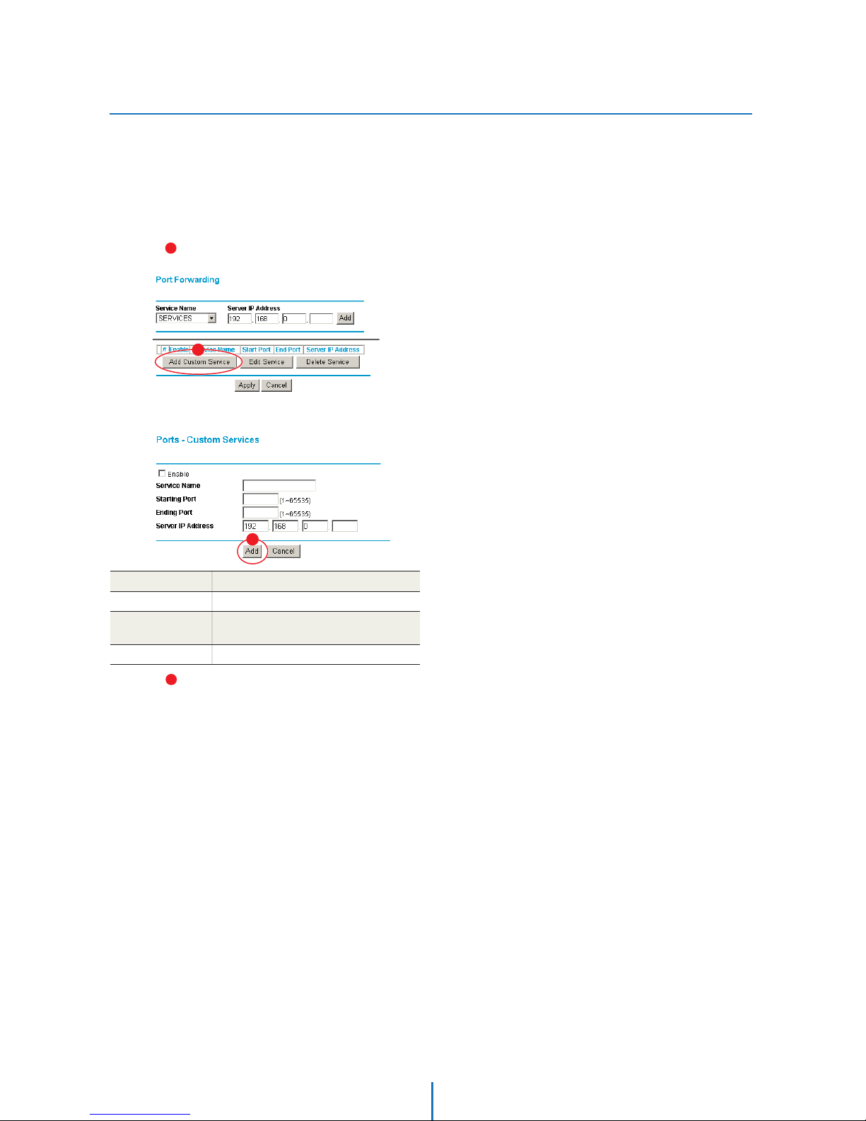
C : Port Forwarding
Appendix -
For Netgear RP614 routers:
1) Input http://192.168.0.1 in address bar of web browser.
http://192.168.0.1 is the default IP address.
2) If it asks ID and password, input admin as ID and password
as password.
3) Click “Port Forwarding” in "Advanced".
4) Click " Add Custom Service" button in Port Forwarding
page.
5) Input proper values in "Ports - Custom Services" page as
below.
6) Click " Add" button.
7) With the same method as above, add Video Server Port.
8) Click "Apply" button to finish Port Forwarding.
3.
Enable
Service Name
Starting/
Ending Port
Server IP Address
Check it.
Input IP Camera name.
Input IP Camera Web Server port.
Starting Port should be same as Ending Port.
Input IP Camera IP Address.
5
1
2
1
2
51
Page 52

FAQ
My POWER light is not on?
Power is not being supplied to the unit. Please use the power
supply shipped with the unit and verify that a power source
is active from the attached power outlet used to connect the
adapter. You can test this by plugging in any other electrical
device and verify its operation. After using the power supply
shipped with the product, checking the power source, and
reinserting the power connector into the IP Camera, please
call our Support Center. The power supply may be defective.
My ACTIVE light is not flashing?
Verify the power supply to the unit. Power off the unit and
back on again, wait 1 minute, if the ACTIVE light still does
not begin to flash, you will have to set the unit to its factory
default (THIS WILL DELETE ANY CONFIGURATION AND SET
THE UNIT TO THE FACTORY DEFAULTS). Power on the unit
and insert the end of a paper clip into the small recessed
opening on the back of the unit. Use the clip to press the
button located within that opening.
My LINK light is not flashing or solid?
Verify the cable connection. 99% of the time the cable’s
connection to the unit is causing this problem. Try using a
different network cable or crossover cable (for PC connection
only). Try reinserting the cable, if this still doesn’t solve the
problem call our Support Center.
I can access the video server on my LAN, but not from the
Internet.
Verify that your router (if applicable) has port forwarding
properly configured. If accessing from our DDNS service,
verify correct serial number. Firewall issues may prevent user
access.
How do I open an MS-DOS or Command Prompt?
t8JOEPXT.&6TFST
4UBSU1SPHSBNT"DDFTTPSJFT.4%04QSPNQU
t8JOEPXT916TFST
Start > (All) Programs > Accessories > Command Prompt
How do I find out my IP address information if my settings
were automatically detected?
1.
2.
3.
4.
5.
6.
Windows 98 / ME Users
0QFOBO.4%041SPNQU
"UUIFQSPNQUUZQFiXJOJQDGHwXJUIPVUUIFRVPUBUJPONBSLT
6TFUIFESPQEPXOMJTUUPTFMFDUZPVS&UIFSOFU"EBQUFS
(not a PPP adapter)
/PXZPVXJMMTFFZPVS*1"EESFTT4VCOFU.BTLBOE%FGBVMU
Gateway information
5) For DNS information contact your Internet Service Provider
Windows 2000 / XP Users
1) Open a Command Prompt
"UUIFQSPNQUUZQFiJQDPOGJHBMMwXJUIPVUUIFRVPUFT
3) Near the end of the information supplied, should be your
current IP address, subnet mask, default gateway and DNS
servers
I can’t connect!!
In the case of a connection failure.
.PEFN3FCPPU.PEFN3FCPPU'JOJTIFE3PVUFS3FCPPU
> Router Reboot Finished > IP Camera Reboot > IP Camera
Reboot Finish > Verify DDNS and IP Camera connection, if
applicable.
How do I “PING” an IP address?
0QFOBO.4%04PS$PNNBOEQSPNQU
"UUIFQSPNQUUZQFiQJOHYYYYYYYYYYYYwXJUIPVUUIF
RVPUFTBOESFQMBDFUIFiYwTXJUIBO*1BEESFTT
3) Press Enter
I’m accessing my video server remotely over the Internet
and the video stream is choppy, is this normal?
Yes. The frames per second received remotely are
determined by your bandwidth capabilities both at your site
where the IP Camera is installed and your remote location.
The lower of the two sites will determine how fast your
video stream is received. It is recommended to have at least
B,CTFDVQTUSFBNDPOOFDUJPOGSPNUIFTJUFXIFSFUIF
IP Camera is installed. Lower speeds will operate properly,
but provide poor remote performance. The Faster the
Internet connection at both ends, the faster the video
stream.
How do I enable or check ActiveX on my browser
0QFO*OUFSOFU&YQMPSFS5PPMTPOUIFNFOVCBS*OUFSOFU
Options > Security Tab > Custom Level > Scroll down and
WFSJGZUIBUZPVBSFQSPNQUFEPSIBWFFOBCMFE"DUJWF9
DPOUSPMTBOEQMVHJOTUPCFEPXOMPBEFEBOEFYFDVUFE
DMJDL0,SFTUBSUCSPXTFS
How do I reset the unit to factory defaults?
On the underside of the unit you will find a recessed opening
MPDBUFEOFBSUIFUPQMFGUTJEFPGUIFMBCFM1PXFS0/UIFVOJU
and use a paper clip to push the reset button within that
opening. You should then see the ACTIVE light turn off and
after a few seconds the ACTIVE light will begin to flash,
signifying a successful reboot. If the ACTIVE light does not
turn off after depressing the reset button, please try holding
the button in for a few seconds and releasing. YOU WILL LOSE
ALL DATA THAT HAD BEEN ENTERED PREVIOUSLY AND THE
*1$".&3"8*--#&4&550*54'"$503:3&4&54
7.
8.
9.
10.
11.
"QQFOEJY
52
Page 53
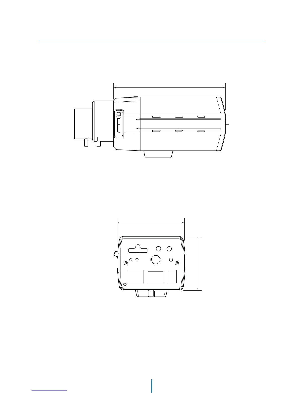
Unit: mm
125
60
75
Dimension
Specifications -
53
Page 54

GENIE CCTV LTD.
CCTV House, City Park, Watchmead, Welwyn Garden City, Hertfordshire, AL7 ILT
Tel: +44 (0) 1707 330541 Fax: +44 (0) 1707 330543
www.geniecctv.com
Edition. GN-February 2014
 Loading...