

Page 1
Operation and
Maintenance Manual
3628336241
TABLE OF CONTENTS
Warranty Information ................... 2
Safety Information ..................... 3
Safety Features ......................... 3
Important Installation Instructions ....... 3
Pre Installation Checklist .............. 46
Adjustments .......................... 7=8
Programming the Remote Control ..... 89
Installing Lightbulb and Lens ............ 9
Scheduled Maintenance ............... 10
Troubleshooting Guide ............. 1011
Wiring Diagram ........................ 12
Parts Lists and Exploded Views ...... 1213
Accessories ............................ 14
COMPLETE WITH mNTELLlCODE
REMOTE CONTROL AND SERIES li
For up to 7'-6" tall Doors. (Extension Kit avaimable for 8' Doors)
included Wail Control MUST be installed prior to Operation of
this Garage Door Operator.
Safe-T-Beam ®Safety Reverse System Must be installed and
the Force Controls MUST be Properly Set to close door.
This Equipment meets or exceeds all Federal, State and UL325
Page 2
THEGEN|ECOMPANYLIMITEDWARPJ ,NTY
What iscoveted?
Any defect [n material and product workmanship from personal,normal
household use [n accordance with the Owner's Manual.
For how long?
MODEL2560... 1Syears on motor, 3years all other parts.
MODEL3560... Lifetime' on motor,3 years allother parts.
%[fedme=Aslong dsyou own your home.
Who gets the warranty?
This warranty is limited to the consumer who originally purchased
the product.
Geographic scope:
This warranty applies only to units installed and operated within the country
where they were purchased.
Limitations:
IMPLIEDWARRANTIES,INCLUDINGTHOSEOFFITNESSFORA PARTICULAR
PURPOSEANDMERCHANTABILITY(ANUNWRITTENWT_RRANTYTHATTHE
PRODUCTISFITFORORDINARYUSE)ARELIMITEDTOONEYEARFROMTHE
DATEOFPURCHASE.GENIEWILL NOTPAYFOR:LOSSOFTIME;
INCONVENIENCE;LOSSOFUSEOFYOURGENIEPRODUCTORPROPERTY
DAMAGECAUSEDBYYOURGENIEPRODUCTORITSFAILURETOWORK;ANY
SPECIAL,INCIDENTALORCONSEQUENTIALDAMAGES;ORANY DAMAGES
RESULTINGFROMMISUSEORMODIFICATIONOFYOURGENIEPRODUCT.
Somestatesand provinces do not allow limitations on how long an implied
warranty lasts or the exclusion of incidental or consequential damages,sothe
above limitations or exclusionsmay not apply to you.
This warranty isthe only one we will give onyour Genie product, and it sets
forth allour responsibilities regarding your Genie product.There areno other
expresswarranties.
Stateand province rights:This warranty givesyou specificlegal rights,and you
mayalso have other rights which vary from stateto state and province to
province.
How to get warranty service:
To obtain warranty servicefor your Genie product, you must provide proof of
the date and placeof purchaseof the product.
1.Do-It=Yourself-Service.
Callthe Genie CustomerServicetoll free at 1.800.354.3643to speak in
person to atrained Genierepresentative for assistancein diagnosing the
problem and arranging to supply you with the required parts for do-it-
yourself repairs.Trained servicerepresentatives areavailable Monday-Friday,
8:00a.rn.- 9:00 p.m.,EasternTime,and on Saturday,10:00a.m.to 7:00 p.rn,
EasternTime (subject to holidays)You may alsoget the information you
needat www.geniecompony.com.
2,Service From Authorized Dealers.
YoualsomayobtainwarrantyservicefromGenieauthorizeddealersbycallingthe
GenieCustomerServiceat1.800.354.3643or byvisitingw_geniecomporry.com
beforeschedulingwarrantyservice.Ifwarrantyserviceisprovidedbyanauthorized
dealer,Geniewilt provideallrequiredpartsunderwarrantyat nochargetoyou,but
thedealersareindependentbusinesspeopleandmayrenderabenchor servicecall
chargeforthek services.Geniewill notreimburseyouor otherwisebe responsiblefor
thosecharges.
Wesuggestthat youretainyouroriginalpackingmaterialinthe eventwechooseto
repairor replaceyourGenieProductandrequestthat you shipit to us.Besureto
includeyourname,address,telephonenumber,proofofdateandplaceofpurchase
andadescriptionof theoperatingproblem.Afterrepairingor replacing,yourGenie
product,wewill shipitto yourhomeatnocostto youfor partsandlabor,butyouwill
haveto payaminimumof$5.00for shippingandhandlingcharges.
Yourchoiceofeitheroneofthe above-describedserviceoptionsisyourexclusive
remedyunderthis warranty.
What this warranty does not cover:
Thiswarrantydoesnot coverbatteries(whichareconsideredreplaceableparts),
installation,commercialuse,defectsresultingfromaccidents,damagewhilein transitto
ourservicelocationor damageresultingfromalterations,misuseorabuse,lackof proper
maintenance,unauthorizedrepairormodificationofthe product,affixingofany
attachmentnotprovidedwiththe product,programmingof the RemoteControl
Devices,Safe-T-Beam®adjustment/cleaning,staplesthroughwiring,pinchedor broken
wires,Carriagedisengaged,ForceContro!adjustments,doorout of balance,broken
springsorcables,poweroutages,useof extensioncords,missingordamagedpartson
discounted,clearanced,finalsaleortaped cartons,phantomoperations(laborisnot
coveredif Openerisfunctioning properlywhiletechnicianisin garage),fire,flood,or
actsof God,or otherfailureto followtheOwner'sManual
Pleasenote the following information,soit is available if you
need to call us.
Date Purchased / /
Serial Number
Operator Model
Remote Control Model
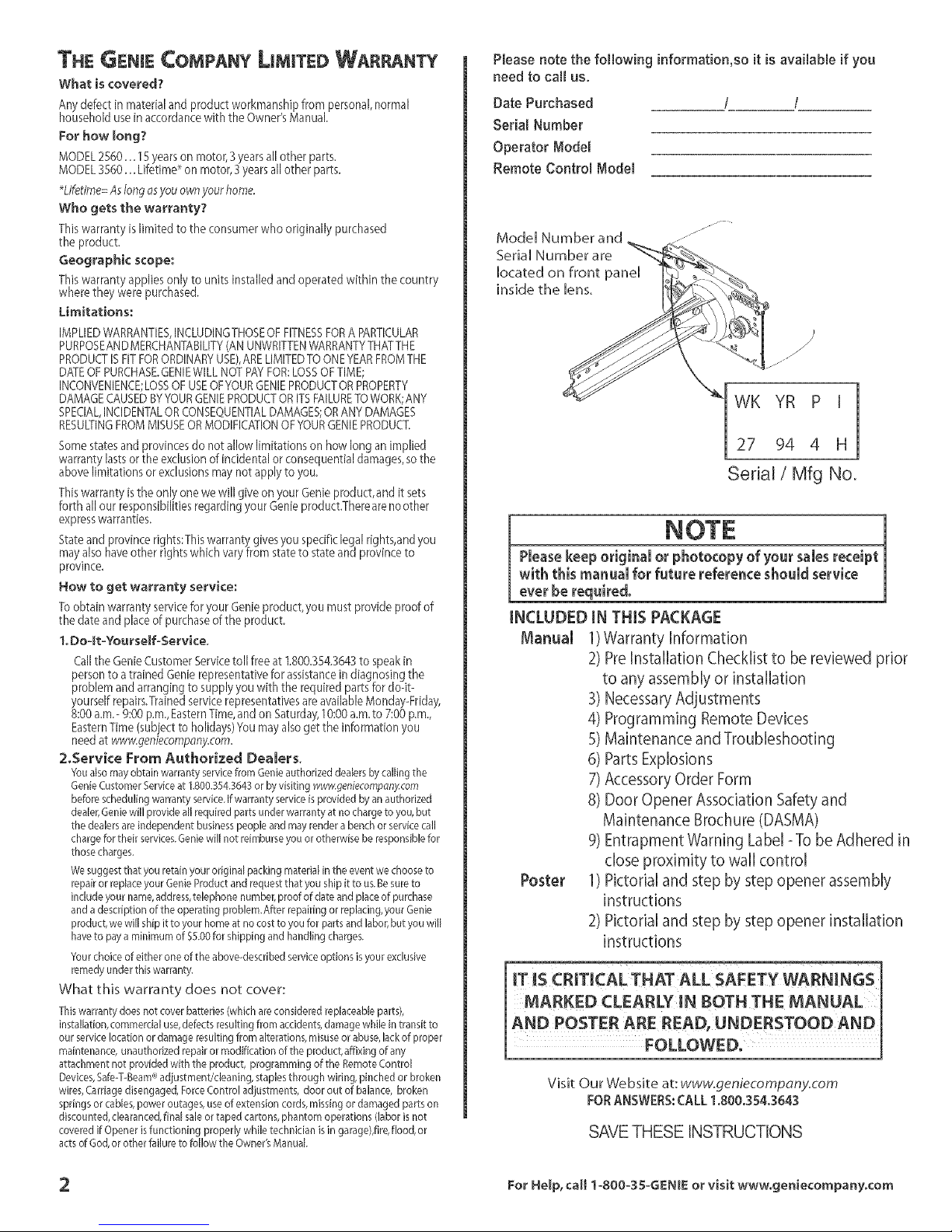
Model Number and
Serial Number are
located on front panel
inside the lens,
jj_
}
/
./
j_
WK YR P [
27 94 4 H
Serial/Mfg No.
Pleasekeep original or photocopy ofyour sales receipt
with this manual for future reference should service
ever be requiredo
INCLUDEDIN THIS PACKAGE
Manual 1)Warranty Information
2) Pre Installation Checklist to be reviewed prior
to any assembly or installation
3) Necessary Adjustments
4) Programming Remote Devices
5) Maintenance and Troubleshooting
6)PartsExplosions
7)AccessoryOrderForm
8) Door Opener Association Safety and
Maintenance Brochure (DASMA)
9) Entrapment Warning Label =To be Adhered in
close proximity to wall control
Poster 1) Pictorial and step by step opener assembly
instructions
2) Pictorial and step by step opener installation
instructions
iT IS CRITICAL THAT ALL SAFETY WARNINGS
MARKED CLEARLY [N BOTH THE MANUAL
AND POSTER ARE READ, UNDERSTOOD AND
FOLLOWED.
Visit Our Website at: www.geniecompany.com
FORANSWERS,"CALL 1,800,354,3643
SAVETHESE INSTRUCTIONS
2 For Help, call 1=8OO-35-GENIE or visit www.geniecompanyocom
Page 3

OVERVIEW OF POTENTIAL HAZARDS
Overhead doors arelarge,heavy objects that movewith the help ofsprings under high tension and electric motors. Sincemoving objects, springsunder
tension,and electricmotors can causeinjuries,your safetyand the safetyof othersdepend onyou reading the information in this manual. Ifyou have
questions or do not understand the information presented, callTheGenie Company.oryour localGenieDistributor.
Hnthis section, and those that follow, the words Danger, Warning and Caution are used to emphasize important safety
information. The word:
_, DANGER; indicates an imminently hazardous situation which, if not avoided, will result in death or serious injury.
A WARNING; indicates a potentially hazardous situation which, if not avoided, could result in death or serious injury.
A CAUTION; indicates a potentially hazardous situation which, if not avoided, may result in injury or property damage.
The word NOTE is used to indicate important steps to be followed or important considerations.
POTENTIALHAZARD
MOVINGDOOR
ELECTRICALSHOCK
HIGHSPRINGTENSION
EFFECT
WARNING:
Could result in death
or serious injury.
WARNING:
Could result in death
or serious injury.
WARNING:
Could result in death
or serious iniury.
Keep people clear of opening while door is moving.
oDo Not allow children to play with the door operator.
Do Not operate a door that jams or one that has a broken spring.
oTurn off power before removing operator cover.
oWhen replacing cover, make sure wires are not pinched or near
mowng parts.
oOperator must be properly grounded.
oDo Not try to remove, repair or adjust springs or anything to
which door spring parts are fastened, such as, wood blocks,
steel brackets, cables or other like items,
oRepairs and adjustments must be made by a trained door
system technician using proper tools and instructions,
MPORTANT INSTALLATION
NSTRUCTIONS
zLWARNING:
TO REDUCETHERISKOF SEVEREINJURYOR DEATH:
1 READAND FOLLOW ALL SAFETY.INSTALLATIONAND
OPERATIONINSTRUCTIONS.If you have any
questions or do not understand an instruction, call
your authorized Genie installation professional.
2 Do Not install operator on an improperly balanced
door. Animproperly balanceddoor couN cause
severe injury. Repairs and adjustments to cables,
spring assembly, and other Hardware must be made
by a trained service person using proper tools and
instructions.
3 Remove all ropes, and disable all locks connected to
the door before installing operator.
4 tnstall door operator 7 feet or more above the floor.
Mount the emergency release knob 6 feet above
the floor.
5 Oo Not connect the operator to the source of power
until instructed to do so.
5 Locate the control button:
[ Within sight of door,
At a minimum height of,5 feet so small children
cannot reach it_
, Away from all moving parts of the door.
7 Install the entrapment WARNING labet next to the
wal button or console. Install the emergency release
tag on, or next to, the emergency release
8 The operator must reverse when the door contacts a
1-1/2 inch high object on the floor at the, cen!er of
the doorway[Thisisabout the sizeof a2 x 4 board
laid flat.
PREVENTION
SAFETY FEATURES
Safe-T-Beam ® (STB) Non-Contact Reversing System
Places an invisible beam across door opening, that reverses
the door during down travel to the fully open position if
anything passes through beam.
Safe-T-Reverse ® Contact Reversing System
Automatically stops and reverses a closing door within 2
seconds of contact with an object.
Safe-T-Stop ® Timed Reversed System
Automatically opens a closing door, if door does not close
within 30 seconds,
ForceGuard ® Control
Used to set the force required for opening and closing
door. For maximum safety, set the minimum force required
to fully open and close door.
Automatic Lighting System
Light bulbs up to 60 Watts max., used for safer entries and
exits, The lights turn on when door isactivated and
automatically turn off 4,5 minutes later.
Manual Emergency Release
Allows the garage door to be opened or closed manually
for emergencies or maintenance,
For Help, ca!l 1-800-35-GENIE or visit wwwogeniecompany,¢ora 3
Page 4

PRE-INSTALLATiON CHECKUST
This Opener includes parts and supplies needed to install in most
garagesand connect to most garage doors. There aremany variations
of garages and garage doors, A few additional parts and supplies may
be needed to install Opener into your garage and connect to your
garage door. While checking items listed below, note any additional
items you will need,
Tools used in this section:
12'+Tape Measure • Pendl • Ladder • Level
Check following items before assembling Opener:
CHECK DOOR CONDiTiON AND
THICKNESS
Checkcondition of vertical stile in center of door, and its connection to
door's top and bottom beams. (Figure 2)
A If door frame isnailed together and not a solid connection, door
frame must be braced or reinforced before installing Opener,
B If door is'lightweight" (made with frame and skin- not solid),
door (including door frame) must be braced or reinforced before
installing Opener.
C Adoor opener reinforcement bracket may also be needed to
connect garage door to Opener's Door Bracket. This Opener is
designed for instalIation on a proper{y braced sectional door or
solidly braced one-piece door.
D Contact your Genie Factory Authorized Dealer or dealer of your
garage door for any necessarybracing and a door opener
reinforcement bracket (if needed) before proceeding.
E If you haveawooden door, measuredoor's thickness. If your door
islessthan 2"thick, brace door or useshorter Door Bracket Lag Screws
(1/4" x I-I/4" - not included)
SECTIONAL DOOR, TORSION SPRINGS SECTIONAL DOOR, EXTENSION SPRINGS
J'_;:>" Extension
Center "::::-_] :: I]
ONE-PIECE DOOR, TRACKLESS
Header Area
q_:]]
Center Stile
Figure 2 Note DoorType
MEASUREGARAGEDoor HBGHT
A
Measuredoor height (floor to top of door) using atape measure.
B
This new GarageDoorOpener isdesigned for doors up to and
including 7'6" tail.Ifdoor height is 7'6" or lesscontinue to CheckStep 4.
C Ifdoor height is8'-0'_you need a Rail Extension Kit.(Figure 3).
(SeeAccessoriesOrder Form,Page14).
D Ifthe door height istaller than 8'-0",the opener you purchased is
the wrong version.Contact your Customer ServiceRepresentative
at 1-800-354-3643.
E×,eos oofor
8"door
@m-- _ ---e
l__ Figure 3 Rail Extension Kit
CHECK DOOR HEADER AREA
CHECK GARAGE DOOR
ALIGNMENT_ OPERATION_
AND BALANCE
A Raisedoor,check alignment and seeif it moves freely (Figure 1). If
door appearsout of alignment, binds, ordoes not move smoothly,
contact a GenieFactory Authorized Dealerordealer of your garage
door for repairsand adjustments to door mechanism,
B Raisedoor to 3' - 4' above ground and carefully let go, Door
should stay stationary. Slight movement is acceptable, More than
slight movement means door is out of balance, Contact aGenie
FactoryAuthorized Dealer or dealer of your garage
door for repairsand adjustments to door mechanism,
KEEPFEET CLEAR OF DOOR
Sectional _ _q--_j'_ One-Piece
Door _ - Door
Figure 1 Checking door balance
C Checkdoor type. Make anote of whether it isa sectional or aone-
)iecedoor for reference later (Figure 2).
The header is a heavily reinforced section of the wall just
above the top of the garage door opening.
A Findvertical center line of door and header:
Closedoor.
Measuredoor width at top.
Marka point atcenter of door and on header directly
above door. Drawa center line to connect points.
B FindHeaderBracket mounting height (Figure 4): (Donot attach
Header Bracket).
Raisedoor,watching top edge of door and stop door
when its edge reaches its highest point.
Measuredistance ("H") from top edge of door to floor.
Forsectional doors, add 2-1/2" to "H': Marka point
on center line. Bottom of HeaderBracketwiII be
installed here.
Forone-piece doors, add 6" to'H': Mark this point on
center line. Bottom of Header BracketwiII be
installed here.
SECTIONAL DOOR ONE-PIECE DOOR
H+24/2"_ _ H+d"
/ 7
HEADER _IEADER
Ifyour door Sticks,binds,or isout of balance,have it adjusted
bya Genie Factory Authorized Dealer. Door springs,cables,
pulleys, brackets and associatedhardware are under extreme
tension and can Causeserious injury or death.
4 For Help, call 1-800-35-GENIE or visit www, geniecompanyocom
Figure 4 Find Highest Point of Trave[
Page 5
o Foralltypesand stylesof doors:
- ff the ceiling ,inyour garage is so low that there is
not at least a 3 space above the Header Bracket
mountingpolnt, contact a Genie Factory
AuthorizedDealer.
If a door spring isin the way, place the Header Bracket
above the spring. Do Not move the door spring.
Perforated Straps
FiNiSHEDCEILINGS
Locateceiling joists or trussesusing
astud finder or similar device.
Attach angle iron(not included) to
joistsor trussesthrough finish
material using Lag Screws.
Door springsareunder extremely hi
should be handled ONLY by a trained professional. I
C Checkwall for a stud ora solid header at your mark: (Ifchecking a
finished waJi,a stud finder may be helpful).
, Iflocation isabove Header,a 2" x 6" board must be
screwedto studs beside your mark with at least two Lag
Screwsand Flat W'ashers(not provided).
Transferyour markto new mounting board.
CHECK POWER HEAD
MOUNTING AREA
Check ceiling or space above where Opener Power Head will be
mounted (Figure 5): There must be a 120Volt grounded outlet or
wiring box within 3 feet of Power Head.
outlet
(7'-6"door
Figure6B
CHECK CEmLmNG FOR GROUNDED
PowER SOURCE
A Checkthat there is a 15Amp 120Volt grounded electrical
outlet or grounded permanent wiring box (per building code)
within 3'of Opener Power Head:Figure 5
• If not,an outlet or wiring box must be installed. Contact
alicensed electrician for installation.
• If building codes require permanent wiring, Power Head
must be partially disassembled to install appropriate
wiring in placeof PowerCord. (SeeAssemblyand
Installation Poster.)
Permanent wiring must be installed by a Licensed
Emectri¢ian. Not all Genie Factory Authorized Dealers
are Licensed Electrician's. Contact someone who isa
Licensed Electrician.
WARNING •
Do Not use an extension cord! Extension cords can
De Net use portable generator! This product is
designed to operate using standard house current.De
Not use alternate power supplies,
0
Door Center Line
Figure 5 Check Power Head location
A The measurements above aretaken from the garagedoor
centerJinetoward the rear of the garage.
B Findlocation of ceiling joist or truss above where Opener Power
Headwill be and estimate type and quantity of materials needed for
your installation (Figure 5A & B).
MOUNTING EXAMPLES
Perforated Angle Iron Conduit
Figure5A
OPENCEILINGSStrapsand angle iron may attach directly to joists
or trusses.
For HeJp, can 1-800-35-GENIE or visit www,geniecompany,¢om
Wood
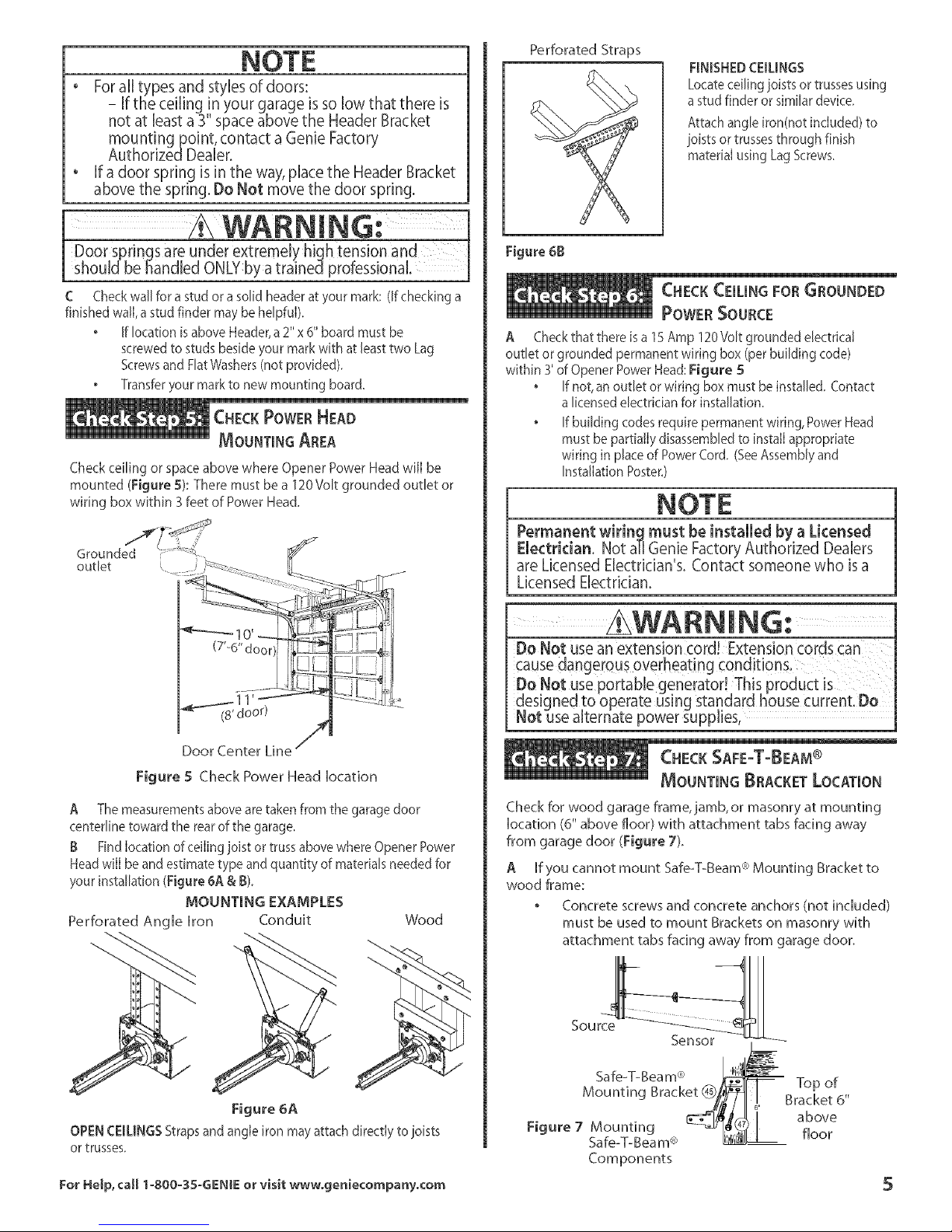
MOUNTmNG BRACKET LOCATmON
Check for wood garage frame, jamb, or masonry at mounting
[ocation (6" above floor) with attachment tabs facing away
from garage door (Figure 7L
A If you cannot mount Safe-T-Beam_ Mounting Bracket to
wood frame:
Concrete screws and concrete anchors (not incHuded)
must be used to mount Brackets on masonry with
attachment tabs facing away from garage door.
Source
Sensor .,d_-,
Safe-T-Beam® _ Top of
Mounting Brack_/_ !.. Bracket @'above
, _-
Figure,Mount,ng
Safe_T_Beam® _ floor
Components
Page 6

RECOMMENDED TOOLS
A
Tools (Figure 8):
B
Additional took to make installation easier:
Slotted and phi[Hps screw=driver bits
Stud finder
Sheebmeta[ cutting snips
REMOVE EXISTING GARAGE
Door LocKs
Check that the garage door locks, rope, and T-Handles are
removed from the garage door before starting the instaHHation.
A ffyour garage does not have a separate entry door, it is
highHy recommended to install[ a Genie Emergency Release Kit
(GER-2). Emergency Release Kit lets you open the garage door
from outside if there is a power failure. (Please see Accessories
Order Form on page 14.)
Before going further, get any items and tools if needed
for your installation
_7 Garagedoor frame reinforcement brackets,screws,bradng
or reinforcement kits (dealer)
_7 LagScrews(1-1/4") for a wood door lessthan 2" thick (store)
_7 Electricaloutlet and/or wiring (supplied by alicensed electrician)
_7 Sufficient angle iron or strapping for hanging PowerHead (store)
_7 60Wan light bulbs (Rough service bulbs recommended)(store)
_7 GER-2Emergency ReleaseKitfor entry during power failure (store)
_7 Wood for header,ceiling, and/or door braces (store)
_7 Masonry fastenersfor Safe-T-Beam€:'Bracket installation (store)
_7 Safe-T-Beam_"BracketExtensions (dealer)
_7 Masonrydri[[ bit (store)
_7 ExtensionKit (for 8'Garage Doors)(dealer)
IMPORTANT
SAFETY INSTRUCTIONS
SEVEREINJURY OR DEATH
1 READANDFOLLOWALLINSTRUCTIONS.
2 Neverlet childrenoperateor playwith the DoorControls,Keepthe
RemoteControlawayfromchildren.
3 Alwayskeepthe movingdoor in sightandawayfrom peopleand
objectsuntil thedoor iscompletelyclosed.
NOONESHOULDCROSS]HEPATHOFAMOVINGDOOR.
4 NEVERGOUNDERASTOPPED.PARTIALLYOPENDOOR.
5 TestOpenermonthly.Thedoo_MUSTreverseoncontactwith
alq/2 highobject(ora2 x4 board[aidflat)atthecenterofthe
doorway'onthefloor. Afteradjustingeitherthe Forceorthe Limit
oftraveLretestthe DoorOpener.Failureto adjustthe Opener
properlymaycausesevereinjuryor death.
7 KEEPGARAGEDOORSPROPERL_BALANCED.SeeOwner's
Manual.An improperlybalanceddoor increasesthe riskof severe
injuryoFdeath. HaveaGenieFactoryAuthorizedDealermake
'epaksto cablesspringassembliesandother hardware.
8 SAVETHESEINSTRUCTIONS.
NOTES, REMINDERS
Go to Assembly and Installation Poster for full
Installation Instructions,
I/t6" 5/32" Tape Measure_
DriH Bit DriH Bit
6' or 7'
Step Ladde_
AdjustaMe Wrench FUat BUade Screwdriver
Hammer Safety, GUasses r/l_ _-_
Hack Saw Wrench
Carpenter's LeveU
Figure 8 Recommended Tools
6 For Help, call 1-800-35-GENIE or visit www, geniecompanyocom
Wire Phi[bps Screwdriver
Stripper
/
1/4" 5/16" 3/8" 7/16" I/2" 9/16"
PenciU
Sockets
Page 7

MAmNTENANCE AND ADJUSTMENTS
ADJUSTING LiMiT SWITCHES
AND FORCE CONTROLS
WARNING:
• A moving garage door can cause senous injury or death.
Keepthe path dear.
o Position the ladder to the side of the Power Head so it is
clear of aHmoving parts of the Opener and the door.
o Set the door Opener to use the minimum force needed
to open the door,
A CLOSE ADJUSTMENT
On front pane[ of Power Head find adjusting screw
marked "CLOSE" (Figure MA-1).
, Gently turn screw counterclockwise until it stops.
- Very little force is required to turn adjusting screw.
PressWall Console to chose garage door.
- Observe if door stops at "CLOSE" limit switch.
(Figure MA-2). If door is fully closed--adjustment is
finished. Go to "OPEN" Adjustment.
- If door stops but is not fully closed,
a. Measure distance between bottom of door
and floor.
b. Move"CLOSE"Limit Switch that same distance
toward door.
- If door stops and/or reverses before reaching the
"CLOSE" Limit Switch
a. Slightly increase CLOSE Force setting (clockwise).
- If door reverses after contacting floor, move Limit
Switch toward Power Head.
- If door fails to move, check Safe=T=Beam®System. See
Troubleshooting Section, pages 10=] 1.
Tighten Limit Switch Set Screw. Do not over-tighten
(strip} Limit Switch Set Screw.
B OPEN ADJUSTMENT
On front pane[ of Power Head find adjusting screw
marked "OPEN" (Figure MA-1).
, Gently turn screw counterclockwise until it stops.
- Very little force is required to turn adjusting screw.
PressWall Console to open garage door.
- Observe if door stops at "OPEN" limit switch.
(Figure MA=2). If door is fully open--adjustment
is finished.
- If door stops but is not fully open,
a. Measure distance between bottom of door
top of door opening.
b. Move"OPEN"Limit Switch that same distance
toward Power Head.
- If door stops before reaching the "OPEN" Limit Switch
a. Slightly increase OPEN Force setting (clockwise).
- If door fails to move, see Troubleshooting Section,
pages 10=11.
Tighten Limit Switch Set Screw. Do not over-tighten
(strip) Limit Switch Set Screw.
Little effort isrequired to turn the Force
Adjusting Knobs.
° If the door stops moving while opening or
closing, adjust the Open Force or Close Force
Controls slightly clockwise (to slightly
increase the force) and retry the step.
. The Open Force and Close Force Controls are to
be set to the minimum force necessary to
ensure the door smoothly opens and
closes completely.
* Ensure the Carriage Assembly isengaged and is
between the two Limit Switches before
operating the Opener.
FORCE
CONTROLS
OPEN
Figure MA-1 Making Force Adjustments
OPEN
i!
CLOSE
, Cycle opener a few times to double check settings.
Repeat adjustment steps as necessary.
For Help, call 1-800-35-GENIE or visit wwwogeniecompany, com
Figure MA-2 Making Force Adjustments
Page 8

ACCESSORIES
f Transmitter Complance Statement
Transmitters comply with al United States and Canadian legal requirements asofthe date
of manufacture, No warranty is made that they comply with al UegaUrequirements of any
other jurisd'iclon. Iftransmitters are to be used in another country, the importer must
determine compUiancew4h anyUocaUUawsand reguUatlonswhich may differ from United
Statesand Canadian requirements prior to use.
Los transmisores cumplen con todas UasregUamentadones UegaUesde los EstadosUnidos
ydeUCanad_,en Uafecha de fabricaci6n, Ninguna garantfa seda que cumplan con todas
as regamentaciones legales de ninguna otrajudsdicci6n. Silos transmisores sevan a
utlizar err otto pais,el importador debe determinar sicumplen con lasreglamentaciones
y leyeslocales que puedao serdiferentes alas reglamentadones de los Estados Unidos y
del Canada, antes de usar losmismos.
Les emetteurs sont conformes £ la r_gementation am@icaine et canadienne _compter
de leur date defabrication, Aucune garantie n'est stipul@ indiquant qu'Is sont conformes
toutes lesprescriptions juridiques d'autres autorit_s, Siles _metteurs sont utlis_s dans
d'autres pays,t incombe a I'importateur d'en d_terminer leur conformit_ aux lois et r_ges
locales pouvant diff@er de celes des Ctats-Uniset du Canada avant toute utlisation
desdits 6metteurs.
Sendeger£te entsprechen alen gesetzlchen Bestimmungen in den USA und Kanada zum
Zeitpunkt der Herstelung.Wir Obernehmen keine Gew£hr[eistung fijr die Einha[tung a[[er
gesetzlichen Bestimmungen in anderen Landem,Solen Sendeger£te inanderen L£ndern
eingesetzt werden, so mussder Importeur vor dem Gebrauch sicherstelen,dass die
Sendeger£te auch sokhen Iokalen Bestimmungen entsprechen, wekhe yon den
Bestimmungen der USAund Kanadasabweichen.
£,x,l)l {_II!II __iiI I £ I?._ £ I I I _I InI _kI_ 4-1 __lSi _t£1t,_l_111°
;017l?,_!20_1-_t-_)'#,_lo)[_1c@.]1t¢'o5)tI, BI tl&l_',(0{_/IJ/E Y_,'L0 i)]_gR$]]Z)_
PROGRAMMING THE
REMOTE CONTROLS
, Each Remote Control must be programmed
separately.
° The Remote Controls will not cause the door
Opener to close the garage door if the Safe-T-
Beam®System is malfunctioning.
° When programminc) the Remote Controls, they
must be at least 24 from the Antenna Wire.
Ifthe red Learn Indicator Light blinks
approximately 4 times per second,
lrogramming has stopped. If programming
as stopped, repeat the above steps.
Each Button on a 2 or 3 Button Remote Control
isfor a different Opener. You cannot use more
than one Button per Remote, per Opener.
° A maximum of seven Remote Controls or
Wireless Keypads can be stored into the
Receiver at one time. If a Remote Control
becomes lost, or if you want to delete a Remote
Control or Wireless Keypad, see To EraseAll
Receiver Memory."
niEi_O]_]E_Eke-XJ_qlA_A_ U@ #q_xb_bA_o£8_slql_Ai ujq3_ _tL_E}£_£!£
SETTING CONTACT
REVERSE FUNCTION
Limit Switch and Force Adjustments must be completed
before checking the contact reverse function (Figure _A-3).
A Open garage door using
Wall Console, Figure _A-3
B Lay a 2" x 4" board fiat in center
of doorway.
C Close door using Wail Console.
Check that door stops and reverses
within 2 seconds after it
contacts board:
, if door does not reverse, decrease
Close Force until door reverses.
, If door still does not reverse,
move Limit Switch toward door.
E Check Safe-T-Beam ° System
operation:
, If beam is blocked, door will
not close.
2" x 4" boa rd
hid fiat
A To program one Button of a Remote Control (Figure MA-4):
Locate Learn Button and Learn Indicator Light
on left side of Power Head (Figure _A-5),
Press and release Learn Button, Red Learn
Indicator Light will blink 2 times per second,
Press Remote Control Button once within 30
seconds, Red Learn Indicator Light will stay lit,
Press Remote Control Button again, Red Learn
Indicator Light will go out, indicating that
memory is stored,
Press Remote Control Button again and the door
will operate,
B Program each additional Remote using step A above
(up to seven),
To Erase AiJ Remotes from Power Head Memory
A Press and hold Learn Button on Power Head for 10
seconds or untl Learn Indicator Light goes out.
Memory is erased:
Program Transmitter/Receiver again as needed.
To Replace Remote Control Battery
A FOR NON-FLASHLIGHTMODELS
Pop offthe back of the transmitter,
- Use coin, pen, screwdriver or any similar device,
- Replace old Battery with new coin type battery,
Replace back of remote,
B FOR FLASHLIGHT MODELS
Slide open battery cover,
- Replace old Battery with new AAA battery,
Replace battery cover,
8 For Help, call 1-800-35-GENl£ or vBit wwwogeniecompanyocom
Page 9

£ WARNING:
A moving garage door may cause senous injury or death.
o Keep people dear of opemng while door is moving.
Do not allow children to play with the Remote Controls,
Ufthe Safety Reverse does mot work properly:
, Close the door and disconnect the Opener using the
Emergency Release Cord,
° Do not use the door Opener, Remote ControB, oJ
Wireless Keypad.
o Refer to the door and door Opener Owner's Manuals
before attempting any repairs.
iNSTALLLUGHTBULBSAND LENs
A Install two 60Watt light bulbs (not included) into Light
Sockets (Figure MA-6):
o Rough service,] 30Volt bulbs are recommended.
B Insert the hooks at the bottom of the Iens into the slots
provided in the front plate of the power head (Figure MA-7).
o Ftip Lensupand fasten with (2) #8-32x 3/8"Phi]]ips Pan
Head Screwswhere indicated.
Remote Control Operation
A Press Button on Remote Control Garage door wH[ move.
B Press Button again. Garage door wi[I stop:
The door automatically stops at the end of the open or
close cycle.
C Press Button again. Garage door will reverse.
1 Button Compact Remote 3 Button Compact Remote
w/Docking Station w/Docking Station
Figure MA-4 Genie Remote Controls
Receiver Learn
Code Button
U_ith Opener. Any 1
moth__pener to operate 1
mune_ stop_,orking. "
Figure MA-6
(not to
scab)
Receiver
Figure MA-5 Learn Code Button and indicator Light
Toprogram a Hemelink ®or CaJ'2U Device:
(This GDO is Home!ink _ end Car2U compotible)
o Follow the Home[ink_)or Car2Uinstructions in your car
owner's manual
For Help, call 1-8OO-35-GENIE or visit wwwogeniecompany,¢om
Figure MA=7
J
J
Page 10

A Monthly:
Door springs and door hardware:
Oil door roller, bearings, and hinges using silicone
lubricant or light oil
WARNING:
If the door fails to reverse on contact with the board
adjust the Close Force Control as specified in Set Limit
Switches and Force Controls on page 7 & 8. If the Opener
still fails,contact a Genie Factory Authorized Dealer for
service or call Customer Service at 1-800-35-GENIE
DO not operatedooiautomaticai[y or manually if springs [
are broken. Contact a Genie Factory Authorized Deater for
service orcaH Customer Service at 1.800.35.6ENIE. 1
, BaHanceDoor.
- CHosedoor.
- ReleaseCarriage Assembly from Rail Assembly by pulling
the Emergency Release Knob towards the door.
- Raisedoor manually 3L 4' and verify' that door staysat
that position. See Check Step 2on page 4.
When the door is 3' _4' above the ground, the door
should stay open. Slight movement is acceptable, ff
the door moves too much, contact a Genie Factory
Authorized Dealer for service or call Customer Service at
1-800=35-GENIE.
- Reattach CarnageAssemb[y to Rail Assembly:
a. Pull the Emergency Release Knob toward Power Head.
b. CHosedoor.
Contact ReverseTest.
- Perform Adjustment 2 on page 8.
B Yearly:
Wipe off oid excess Hubdcant from Drive Screw.
Lubricate Drive Screw with Genie Lubricant GLU-3_
UseONLYGenieLubricant(6LU-3). Other lubricants
may damage the Opener.
GLU-3
Lubricant
FCC AND [C CERTIFIED
this device must accept any interference received, indud
ins interference that may cause undesired operation.
C Asneeded
Replace lightbulbs.(See page 9)
Safe-T-Beam ®System Self-Diagnostic Troubleshooting
Source {Red LED) Sensor {Green LED} Possible Problem solution
ON ON Normal operation None required
OFF OFF
OFF ON • Wiring to Source missing or bad • Check wiring
2 BLINKS, Pause o Beam not aligned o Check Source, Sensor alignment
(Repeat) ON o Beam obstructed o Check for obstruction
2 BLINKS, Pause o Wire to Sensor missing or bad o Check wiring
(Repeat) OFF o Sensor defective o Contact Customer Service
-3 BLINKS, Pause • Sensor receiving interference • Determine source of interference
(Repeat) ON o Check for interference from sun-
4 BLINKS, Pause o Source not sending pubes o Contact Customer Service
(Repeat) • Source defective • Contact Customer Service
ON
• Power Head not powered o Check breakers, fuses, plugs
• Wiring from Power Head bad • Check wiring for obvious shorts
• Power has been interrupted o Remove power and reappiy
o Sensor defective o Contact Customer Service
light or a source unit on an
adjacent door
• Contact Customer Service
1 0 For Help, call 1-800-35-GENIE or visit www, geniecompanyocom
Page 11

Probmem What To Do
Opener does not run
from Wall Control
t
Door Opener starts
for no apparent reason
Door starts down, then
stops before it is
completely closed
Door starts down, then
stops andgoesback up
Door will only run dosed
Doorwill only run open
Lightswill not turn off
Door starts up, but stop'.
before it is
completely open
Operator runs,but door
doesnot move
WallConsoleVacation
Lockfunction does
not work
NoisyOperation
GeneraJ TroubJeshooting
1. Check Lock switch on Wall Control (seeWall Console section on Installation Poster).
2. Check Power Source:
* For Grounded Plug Connection.
- Plug alamp into the electrical outlet used for the door opener.
a. If lamp lights, power source isgood.
b. If lamp does not light, check fuse or circuit breaker.
* For Permanent Wiring Connection.
- Checkfuse or circuit breaker.
3. Check connections (seeWail Console section on Installation Poster):
At Power Head Terminats and Walt Control.
1. Check Wiresto ensure that they are not cut (Stapes can cut insutation and short Wires)
Replaceany shorting Staples and shorted Wires.
2. Was Remote Control lost or stolen? If so,erase all Remote Control codes from Receiver's memory
and reprogram for remaining remote controls. (See EraseAll Receiver Memory on page 11).
3. Ensurethat no Buttons are stuck"pushed-in"on Wall Console or any Remote Controls.
1. Check dose Limit Switch setting (page 7and Installation Poster). Adjust asneeded.
2. Check Force Setting (page 7 & 8).Adjust as needed.
3. Check for shorted wires.
1. If a new installation, check Door Arm position.
2. Check operation of Contact Reversefunction.
3. Check Safe-T-Beam¢_Systemfor beam obstruction or misalignment ofLenses.
4. Check Safe-T-Beam_ Systemdiagnostic code.
5. Check dose Forceadjustment (seeSetLimit Switchesand ForceControls on page 7). Adjust asneeded.
6. Check garagedoorfor binding.
1, CheckOpen Limit Switch for a short drcuit and for proper wiring,
2, Check Open Force adjustment (seeSet Limit Switchesand ForceContro[son page 7& 8). Adjust asneeded.
:3, Check condition ofgarage door and door spring(s),
4, WARNJNIG:If yoususpect a probtem with the garage door hardware or springs, contact a Genie
Factory Authorized Dealer for service,or contact CustomerService at 1-800-3S-GENIE
5. Check position of LockSwitch on Console.
m
1. CheckSafe.T_Beam®SystemasdetaiIed inthe Safe.T_Beam®SystemSeIf_diagn_sticTr_ubIesh__ting Chart
(page10).
2. Check d°se Limit Switch f°r a sh°rt circuit and f°r pr°per wiring'
3. Check CIoseForceadjustment (seeSetLimit Switchesand ForceControls on page 7& B). Adjust asneeded.
1. DisconnectWires connecting WallConsole to PowerHead(see"WalIConsole Installation"- on Installation poster).
Checktheir condition and either replace or reconnect.
2. Until areplacementWailConsolecan be obtained, disconnect Wall Consoleand useonly RemoteControls
or WirelessKeypadto operate Opener.
3. Check for non-compatible wall control.
1. Check (ensure) that garage door and Opener are in good repair,properly lubricated, and properly
balanced as detailed in Maintenance Section.
2, WARNING: Ifyou suspect a problem with the garage door hardware or springs, contact a Genie Factory
Authorized Dea_erfor service, or contact Customer Service at 1-800-35-GENIE,
3. Check Open Limit Switch for ashort circuit andfor proper wiring.
4. Check Open Forceadjustment (see SetLimit Switchesand ForceControlson page 7 &8). Adjust asneeded.
1. EnsureCarriageAssembly isengaged to RailDrive Screw(seeInstall CarriageAssembly-INSTALLATIONPOSTER).
2. Check Forceadjustment (seeSetLimit Switchesand ForceControls on page 7).Adjust asneeded.
3. Check that alIsections of RailDrive Screwareturning when Motor runs. Ifnot:
Checkcondition (not cracked,split,orbroken)and placement of Coupler.Replaceasneeded.
Checkcondition (not cracked,split,orbroken)and placement of Collarand dip. Replacethem
asneeded.
1. EnsureCarriageAssembly isin contact with CloseLimit Switch.
2. Check when door isfully closed,that Carriage activatesClose Limit Switch. If not.adjust position of Close
Limit Switch(Seepage7).
1. Besureallfastenersaretight.
2. Check (ensure) that garage door and Opener are in good repair, properly lubricated, and properly
babnced as described in Maintenance Section (page 10).
m
T
11 For Help, call 1-800-35-GENIE or visit wwwogeniecompanyocom
Page 12

WIRmNG DIAGRAM
[_ WA RNiNG,'_ M;ycauseE!ectrii%_Ck--_
CE
BLACK
o
O
cc
WHITE
2
GREEN /_
PRIMARY
SEQUENCER
ORANGE
THERMAL
PROTECTOR
MOTOR
YELLOW
PRIMARY SECONDARY
GREY
ORANGE
yELlOW
=
=
MOTOR
CAPACITOR
PURPLE
(Vet)
RADIOCONNECTOR
........ u
SEQUENCER/_
HOUSING
WALL
CONTROL
STB
SYSTEM
TERMINAL
STRIP
E
.IGHTS
PARTS IDENTIFICATION
[1],o o,Assembly
Power Head Parts List
item Part Name
1 Power Head Assembly
A Cover (by Series Model)
B Front Plate Assembly
C Light Socket
D Motor Parts
E Receiver Assembly
F Capacitor(By Series/Model)
G Opto Wheel
H Opto-Luctor Assembly
J Sequencer Assembly
K Circuit Board Bracket
L Transformer
M Terminal Strip
N No.8-32 x 1/2" Hex Head Screw
w/Lockwasher
P No.8-32 x 3/8" Slot Hex Head
Screw w/Lockwasher
R Capacitor Isolator
4 1/4-20 Shoulder Bolt
5 1/4" Flange Nut
39 Coupler
41 No.8-32 x 3/8" Phillips
Hex Head Screw
42 No,8-32 x 3/8" Phillips
Pan Head Screw
48 Mounting Straps
49 Light Lens
1
1
1
1
2
1
1
1
1
1
4
1
1
1
1
1
2
2
1
4
2
2
1
For Help, call 1=800=3S-GENIE or visit wwwogeniecompany, com 1:2
Page 13

PARTS [DENTmFmCATmON
[3] AssemUy
i
i
Parts List (co.t')
item Part Name
1 Power Head Assembly (see page 12)
3 RailAssembly(3-piece)
3A First Rail Section
3B Middle Rail Section
3C End Rail Section
4 1/4"-20 Hex Head Shoulder Bolt
5 1/4"-20 Hex Flange Nut
6 Carriage Stop
7 Rail Clamps
8 5/16"Hex Head Shoulder Bolt
9 5/16"Hex Flange Nut
10 Carriage Assembly
11 Collar
12 Retaining Clip
13 Rail Strap
15 Limit Swit(h Assembly
16 #8-32 x 3/8" Hex Head Screw
17 Emergency Release Cord
18 Emergency Release Knob
19 Emergency ReleaseTag (not shown)
20 Header Bracket
21 Door Bracket
22 1/4"x2"LagScrew
23 Straight Door Arm
24 Clevis Pin
25 Cotter Pin
26 Curved Door Arm
27 3/8"x 7/8"Hex Head Bolt
28 3/8" Hex Flange Nut
Number
mnduded
1
1
1
1
1
2
2
1
4
8
13
1
2
2
1
2
2
1
1
1
1
1
7
1
2
2
1
2
2
Parts List (cont9
Part Name
29
Wire (not shown)
30
Insulated Staples (not shown)
31
Wall Button (not shown)
33
Wall Console (not shown)
35
Entrapment WARNING Label (not shown)
36
Safe-T-Beam (STB)Sensor (green LED)
(not shown
37
Safe-T-Beam Source (red LED)
(not shown)
38
Safe-T-Beam Bracket (not shown)
39
Coupler
40
#10 x 1q/4" Phillips Hex Head Screw
43
Safety and Maintenance Guide
(not shown)
44 4
Wire Clip
5/16" x 3/4"Hex Head Bolt
46 5
47 3
1/4"-20 x 3/4" Self-tapping Screw
48 2
Mounting Straps
49 1
Light Lens (see page 12)
50 varies
Remote Control (not shown)
_gsft
varies
varies
30
1
I
2
I
4
1
For HeJp, ca[[ 1-800-3S-GENIE or visit wwwogeniecompany, com 13
Page 14

Garage Door Opener Accessories Order Form
Formu[ario de pedido de accesorios pare abndores de puertas de garaje
Formulaire de commando des accessoires pour ouvre-porte de garage
Foradditionalaccessoriesnotshown.visitourwebsiteatwww.geniecompany.com
Pareaccesodosadicionalesnomostrada,visitenuestrositioweben www.geniecompany.com
pourlosaccessoiressupplBmentairespasmontrB,visiternotrBsiteweb_ www.geniecompany.com
(GI CT390-1 ) 1°Button compact Remote- Allowsremoteoperationof garagedoor.
Cempdmad Monde do Dgtanda- ProporciBnaroperation remotede lapumtade[ garaje.
TBIOcommandocempacto- Pemmttreop&ation _loign-de portedegarage. P/N 36248R $36.50
(G[FT390-1) 1=ButtonRashlight Transmitter - RemoteControllerwith aFlashlight.
1abrocha transmgor do lintorna- Directorremotecon una[intema.
l=boutonnor FOmottourdo lampodo pocho -LecontrOMlr doign_ avecde lampedepoche.
P/N 35657S $45.00
(G[ C[390-3) 3=ButtonCompact Remote- Allowsremoteoperationof3garagedoors.
Do3 botonos Comprimad Monde doDistancia- PropordOnaroperation remotede tres[aspuertasdd garaje.
3°beutonnor laTOIOcommandocompacto -Pennettreop@ation_loign'trois portes
@garage. P/N 36223R $50.00
(GWC-2W} Dduxo WallConsdo - OperatesGarageDoor.Independentlight control.Securityvacationlock.
¢onsda do [ujodo pared - Acciona[apuertadd garaje,Controlde [uzindependiente.Cerradurade
seguridadparavacadones.
La¢onsdo dso[uxodoMur- Acfionne laporte de garage.Commanded'_dairageind@endante.
Intermpteurde verrouilhgede s_curRO. P/N 35661 R $35.00
(GWKPD} wirdoss Keypad-Operates[ntdlicode"GarageDoorOpenerswithout RemoteControlorkey.
Sistomado ontrada per todado numOricoinal_mbrico- AccionaInsabridomsde puertasdegarajeIntellicode sin
controlremoteo Ilave.
SystOmod'ouvro-porto dogarage _ davior sansfib Actinnnelosouvre-pnrtede garageavecIntellicode sans
td_commandeni cir.
P/N 35691R $50.00
(GLU-3} 314oz, ScrewDdvo Lubricant - Ensuresproperequipment wear protection.
3/4once Lubricantodotornillo occionar -Asegmacomponentecorrectoprotection per deterioro.
Laonza 3/4Lubrkant dola vis - Garantlrcomponentexactparsyst_meddenseversuser. P/N 35218A. S $5.00
(6W-2) UniversalWall Button- Providesadditionalconvenientinsideoperation of does _>1
BotBndo pared universal- Propordonaoperad6nconvenientede[apuerto des@el interior.
neuron mural universe[- ActionneFnuvm-portedeI'int@ieurdu garage. P/N 35693R $3.75
(GPS-5} Perfect Step- Ensuresperfectparking. ZZE_....... _-
StopPorfoctd- Aseguraelestacionamientoperfecto.
Butoir Perfect Step'- Permetdestationnmala perfectiondanelegarage. P/N 35677R $4.00
(GABXS} Bolt Drive E×tonsionKit- AnExtenBonthat increasesthe travelofan Openerto accommodatean
eightfoot door.
Juogo dooxtonsi6n do cadonadoslizabla- UnaextensionparaaumentarlaIongituddelabarandadeChain
Glide,paraacomodarunapuertade 8pies(2,43m),
N&ossairo do prolongomont du couikseau - Rallongede prdongeanth coursedeI'ouvre-porteChainGlide
pouruneporte de2,4m (gpi)dehauteur. P/N 35663R $32.00
(LCBX-8} chain Ddvo ExtensionKit- An Extensionthatincreasesthe travelof anOpenerto accommodatean _
eightfoot door. _ )
Juogo dooxtonsi6n de cadonadoslizablo- UnaextensionparaaumentarlaIongituddeh barandadeChain _._/
Glide,paraacomodarunapuerta de8pies(2,43m).
N&ossaira de prolongamant du coulksoau - Raliongede prdongeant[acoursede ['ouvre-pmteChainGlide
pouruneporte de2,4m (8pi)dehauteur. P/N 35679 R $32.00
(GSX-8} ScrewDrive Extension Kit- AnExtensionto increasetravelof anOperatorto accommodate
eightfoot door.
Juago doextension doslizanto do ScrewDdvo- Bnaextensionpareaumentar[acarfarede unabridor _,
desiizaNe,paraacomodarunapuertade 8pies(2,43m.).
N&essaire de raliongodu ScrewDrive- Rallongedeprolongeant la
course@I'ouvre-portepour une portede 2,4m (8pi)de hauteur.(GIRUqT) P/N 35678R $32.00
(60WATT)Enhancad/BoughServiceLight Bulb- Ensuresproperequipment compatabilW /%
Bembilla do60 Vatios- Aseguracomponentecorrectode sBtema. _--_"
Edairagode 60 WATT-Garantircomponentexactparsysteme. P/N 26210A.S $2.73
(GER-2} Emergenoy Release }(it - Provides access to garage from outside in the event of
an electrical power failure.
Juego de pica-porte de pastille - Permitir entrtada desde par fuera de garaje porque corte
de el&trim.
NBcossairee de D_dencbement de seceuro - Le n&essaire de d&lenchement
de secours est consupour vous perme_tre d'accOder Rvotre garage depuis
I'extBrieur en cos de panne de courant et Iorsqu% P/N 35675R $20.00
STB Adapter Brackets (2) - Used in conjunction with standard STBBrackets.They provide
additional clearance and mounting options.
EI adaptador pone entre par_ntesis (2) - Usado en uni6n con par_ntesis uniformes de
montar de STB,ellos proporcionan el espacio libre adicional junto con mortar las opdones.
Croohets d'adaptateur (2} - UtilisB conjointement avec STBstandard mentor les crochets,
ils fournissent le dBgagement supplementaire avec mentor d'options. P/N 34439R.S $4.37
How many?
LQu_ntos_
Ordering Instructions
No C.O.D.shipments. Please include check or money order,
made payable to The Genie Company. Do not send cash.
Allow 34 weeks for delivery.
1-800-3544643. Please have part number and credit card
ready. Mail Order Form to: Genie Company, 22790 Lake
Park Blvd, Alliance, Ohio 44601 .We accept Visa or
Mastercard on phone orders only.
Pleaseadd local salestax if you leUde in one of the states listed
California, Connecticut, Florida, Georgia, Illinois, Indiana, Maryland,
Massachusett_ Michigan, New Jersey, New York, Ohio, Tennessee,
Virginia, Wisconsin
TOTALORDER
SHIPPING& HANDLING
STATESALESFAX
GRAND TO]:AL
S
S 5.o0
S
S
Las Instrucciones que Ordenan
No se aceptan pedidos de page centre entrega (COD).
SirvaseincJuir su cheque o sire postal, Jacuenta pagadera
hecha aTheGenie Company. Noenv[e dinero en elective.
ConcBdanos 3 a 4 semanas para[a entrega. 1-800-35&3643.
Sirvasetenor [istos los nOmeros de[ mode[o yde [atadeta de
cr_dito. Enviar hater un pedido de mercancia a: Genie
Company, 22790 LakePark Bird, Alliance, Ohio
44601Aceptamos pedidos telefBnicos de Visao Mastercard.
Silvase aglegal el impue to de venta local si usted reside en uno de los
Uguientes estados;
California, Connecticut, Florida, Georgia, Illinois, Indiana, Maryland,
Massachusetts, Michigan, New Jersey, New Yolk, Ohio, Tennessee,
VOginia,Wisconsin
TOEAL DEL PEDIDO $
FLETEYMANEJO $ 5.00
IMPUESTODE VENTAS ES-FATAL $
GRANTOTAL $
Instructions Commandant
Pasd'exp_ditioncentre remboursemencVeuillezindure unch#que
ou un mandatbancake,lepayablefaitaTheGenie Company,
N'envoyezpasd'argent comptam.Accordezde 3_4 semainespour
la[ivraison.1-800-354 3643,Ayezsous[amain [enum&o de [a piece
et celuide[acarte de cr_dicMettre _[aposte learmgement a:Genie
Compan_22790LakeParkBlvd,Alliance,Ohio 4400I.Nousaccep
tons loscommandospar t_l@honeavecpaiement parcartede
credit VisaouMastercard.
VeuiIlez indJquel los taxes de vente locales si vous i _sklez clans I'un des _,tats
repertories ci dessous
California, Connecticut, Florida, Geomia, Illinois, Indiana, Mawland,
Massachusetts, Michigan, New Jersey, New Yell<,Ohio, ]%nnessee,
Vagirda,Wiscon in
COMMANDE TOTALE $
MANUTENTION ET EXPEDITION $ 5.00
-EAXE DE VENTE $
TOTAL GLOBAL $
SHIPORDERTO:
ENVIAR MEfiCANCIA CON:
EXPEDIERMARCHANDISE POUR:
NAME/ NOMBflE/ NOM
ADDRESS/ DIRECCION/ ADfiESSE
CITY/CIUDAD/ WLLE
STArE/ EflTADO/ ETAT
ZiP / ( ODIGO POSTAL / CODE POSTAL
(Prices subject to change without notice)
(Valoran el cambio con sujeci6n a sin nora)
(Lee prix assujettissent pour changer sans [a notification)
For Help, call 1-800-35-GENIE or visit www.geniecompany.com
 Loading...