

Page 1

Exclusive Distribution:
WWW.BEGLEC.COM
Page 2
Page 3
1
Page 4
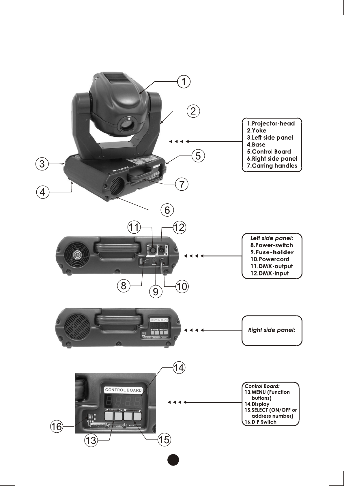
Description of the appearance
2
Page 5
Inspection
Carefully unpack the carton, and make sure if any damage or loss
caused by transportation.
Contact your Geni dealer to assure your right by telephone or
facsimile immediately if damage has occurred or if something is
missing.
Packing List:
A. OBY-5 Moving Head
B.Operating Manual
Bracket
C.
D.GOBO
E. Lamps (Optional)
3
Page 6

Safety instructions
This appliance must be earthed (grounded).
Disconnect power before removing covers or servicing.
Keep case closed while operating.
OBY-5 contains no user serviceable parts. Refer servicing to
qualified technicians only.
Lamp and components become hot during operation. Allow time to
cool before handling.
Keep flammable material at least one meter away from unit.
Do not operate in wet conditions or near liquids.
Keep air vents clear to avoid overheating.
Lamp produces hazardous UV light. Do not look directly at lamp
when lit.
Replace any blown or damaged fuses only with those of identical
values.
4
Page 7
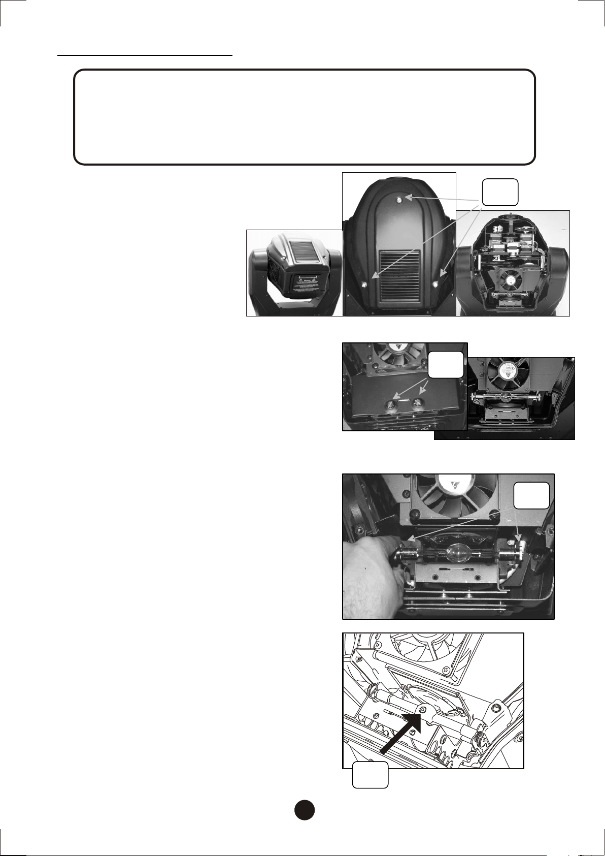
Lamp Installation
Warning!
When replacing the lamp, please wait 15 minutes after powering down to allow the
unit to cool down! Always disconnect from main power prior to lamp replace ment.
Do not touch the envelope (glass area) of the bulb with bare hands. If this happens,
clean the lamp with alcohol and wipe it with a lint free cloth before installation.
1.Keep projector-head upward .Unscrew
thumbscrews (S1) to detach the top
cover.
2. Unscrew screws (S2) to remove lamp
cover and expose lamp compartment.
3. If installing a new lamp, loosen both
screws on the double ended lamp to
allow for the lamp to slide into the
lamp socket slots. Lower lamp
evenly.
4. If replacing a lamp, loosen both lamp
screws (S3) to relieve tension from
lamp socket slots so you can slide the
lamp freely, upwards and out of lamp
socket. Raise lamp evenly to remove.
1
2
3,4
S1
1
S2
2
S3
5. Before you tighten the lamp end
screws, rotate the bulb until the nipple
on the envelope (N) of the bulb is facing
upwards as illustrated.
6. If you are replacing the lamp, you may
want to log the fixture hours in order to
track the lamps use. Navigate to the
(LPti)on the menu display to obtain this
information.
5
5
N
Page 8
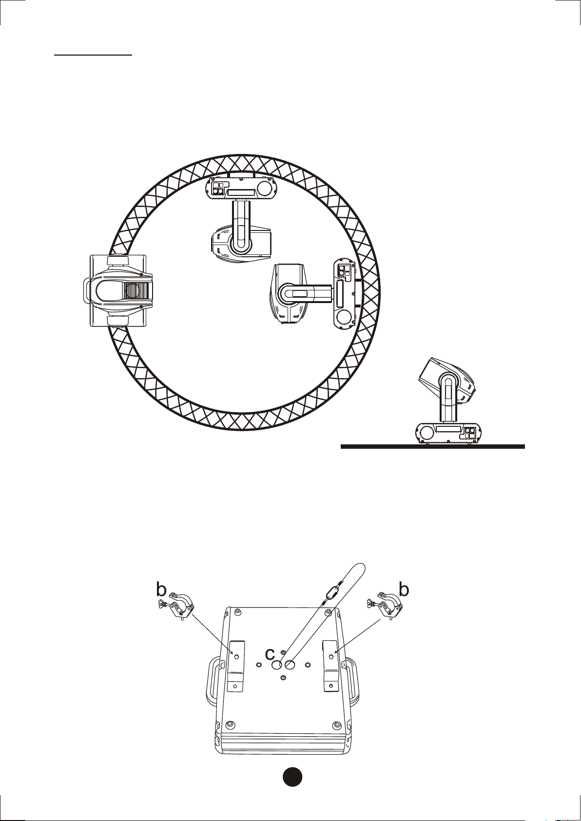
Rigging:
OBY-5 can be set on the flat stage floor directly or use clamp to mount on
any kinds of trusses for fitting the mobility of various venues.
Mount two attached brackets(a) on the bottom (See Figure ), and
collocate the appropriate clamps(b) to rig with trusses. Must use the
safety ropes that can hold the ten times as heavy as the fixture through
the eye bolts(c) on the bottom of the base and trusses; then join the
safety ropes with screw-on carabines(d).
d
a a
6
Page 9
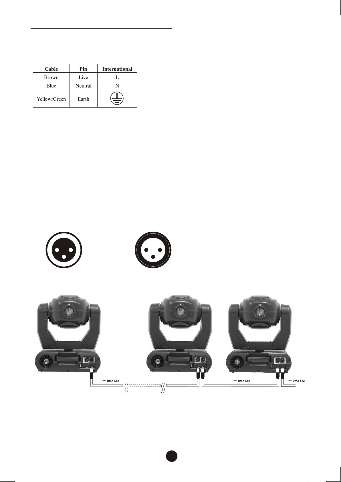
Connection with the mains
Connect the device to the mains with the power-plug.
The occupation of the connection-cables is as follows:
The earth has to be connected! In general, lighting effects should not
be connected to dimming-packs.
Linking
Use 3-pin XLR data cables to link the controller to DMX lighting
equipment.
3-pin XLR connectors are follows:
DMX-output
XLR mounting-socket:
12
3
1:Ground
2:Signal(-)
3.Signal(+)
DMX-input
XLR mounting-plug:
1 2
3
Building a serial DMX-chain:
1:Ground
2:Signal(-)
3.Signal(+)
Connect the DMX output of the first fixture with the DMX input of the
next fixture. And execute all the setups following the abovementioned instruction.
Flip the DIP SWITCH #3 of last fixture to ON position for terminal
confirmation.
7
Page 10
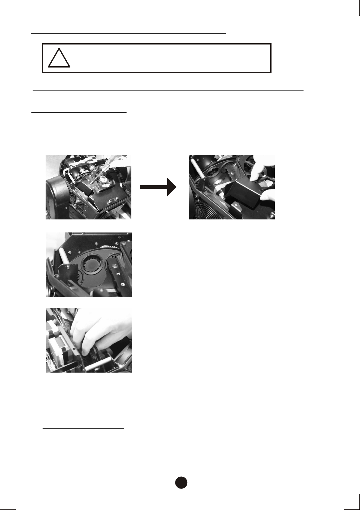
Instructions for gobo replacement
DANGER!
!
Plea se cho ose the suitab le go bo di mensions of thi s fixture. (App endi x A)
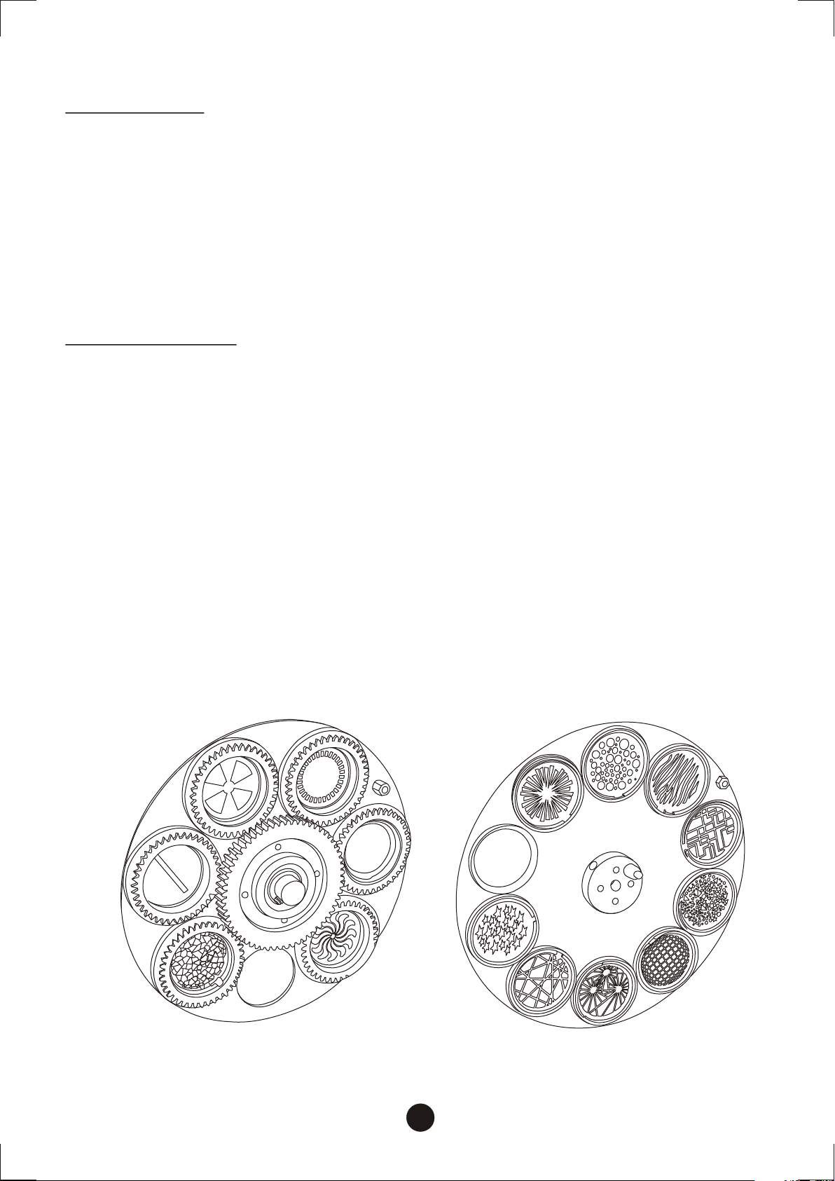
Rotating GOBO wheel
1.Open the top cover (*Refer to the steps of lamp installation.), and
loosen the screws with appropriate tools then extract A . (See the
figures below.)
Install the gobos with the device switched
off only. Unplug from mains before!
A
2.Turn the open (circle) of the GOBO wheel to
"U" shape gap in order to extract the rotating
GOBO easily.
3.Push GOBO & the spring ring out with the
fingers carefully. (*Caution: Avoid falling
the spring ring into the fixture.)
4.Insert the new GOBO and the spring ring (*Press the spring ring
tight with the appropriate tools in order to keep GOBO compact),
put A back and screw up the top cover.
Fixed GOBO wheel
The instructions are the same as changing the rotating GOBO; only
winkle the spring ring out with appropriate flat screw driver before
push GOBO out.
8
Page 11
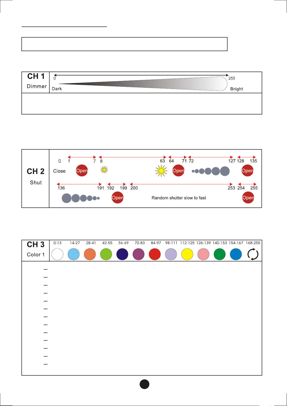
DMX Channel chart
Function of the control channels - 16 bit protocol
Channel 1 - Dimmer intensity
0-255
Gradual adjustment of the dimmer intensity from 0 to 100 %
Channel 2 - Shutter, Strobe
Channel 3 - Color wheel 1
14
28
42
56
70
84
98
112
126
140
154
168
0
13
27
41
55
69
83
97
111
125
139
153
167
255
Open/white
Steel Blue
Orange
Green Blue
Bright Blue
Bright Pink
Red
Deep Blue
Yellow
Dark Pink
Moss Green
Light Blue
Color wheel rotation slow to fast
9
Page 12
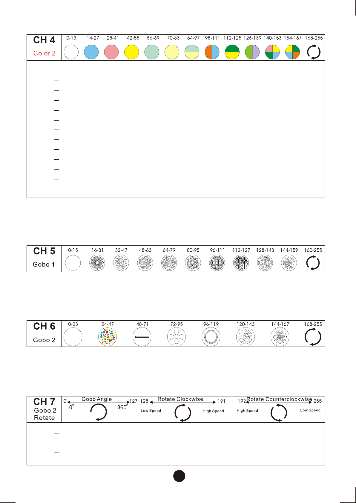
Channel 4 - Color wheel 2
Open/white
Steel Blue
Rose Pink
Yellow
Pale Blue
C.T Orange
Pale Blue- C.T Orange
Steel Blue-Orange
GreenRose Pink-Moss Green
Rose PinkYellow-Moss Green-Orange-Steel Blue
Color wheel rotation slow to fast
Yellow
Yellow-
Steel Blue-Green
14
28
42
56
70
84
98
112
126
140
154
168
0
13
27
41
55
69
83
97
111
125
139
153
167
255
Channel 5 - Fixed gobo wheel
Channel 6 - Rotating gobo wheel
Channel 7 - indexing & Rotating gobo rotation
Rotating gobo angle zero to 360 degrees. adjustment from
Forwards gobo rotation from fast to slow
Backwards gobo rotation from slow to fast
10
128
192
0
127
191
255
Page 13
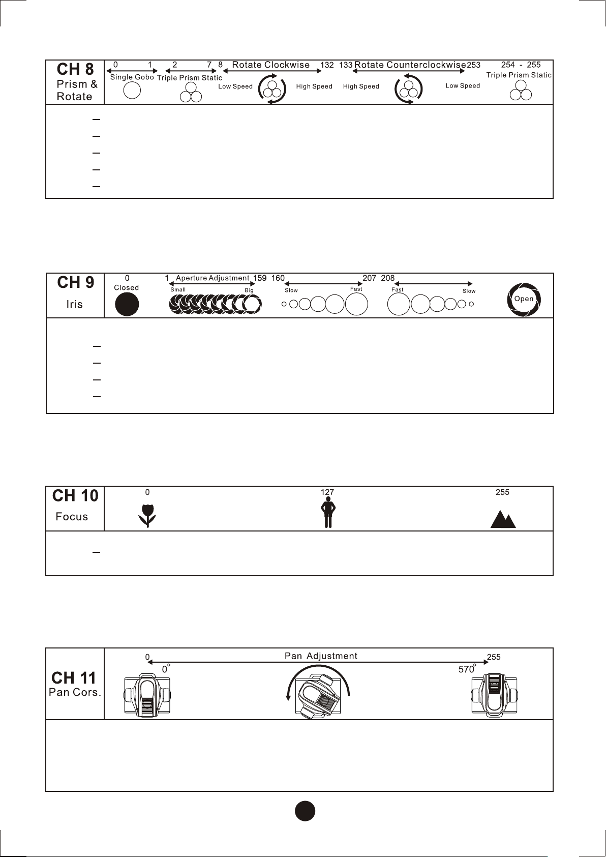
Channel 8- Prism-wheel
Open position
Triple prism static
Triple prism forwards rotation from fast to slow
Triple prism backwards rotation from slow to fast
Triple prism static
133
254
0
2
8
1
7
132
253
255
Channel 9- Iris
Closed
Min. Diameter to max. diameter
Iris-in from slow to fast
Iris-out from fast to slow
Open
1
160
208
254
0
159
207
253
255
Iris-in Iris-out
253
254 -255
Channel 10- Focus
0
255
Focus adjustment from far to near
Channel 11- Pan reguration
CH-11
CH-11
zero to 570 degrees.
zero to 570 degrees.
The “head” of the unit is allowed to turn horizontally from
The “head” of the unit is allowed to turn horizontally from
11
Page 14
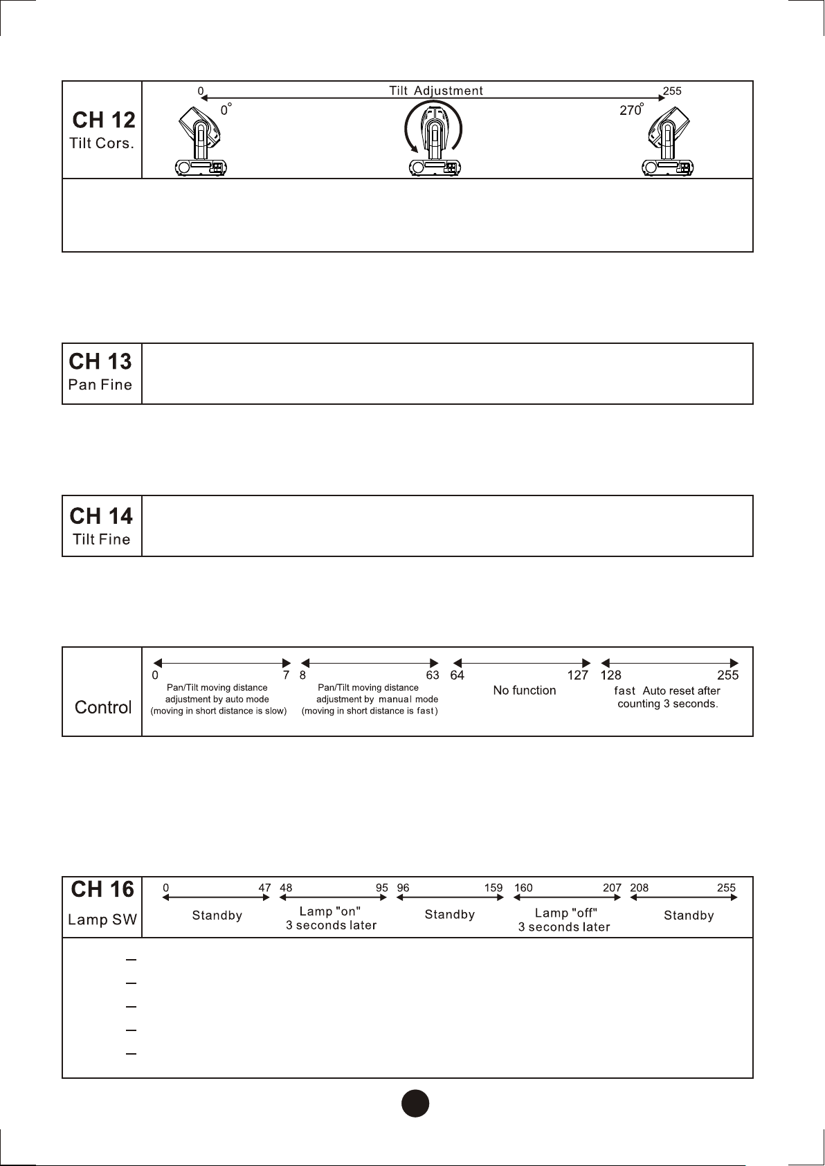
Channel 12 Tilt reguration
The “head” of the unit is allowed to turn vertically from
zero to 270 degrees
Channel 13 Pan fine-tune
While rotating horizontally the “head” is allowed to be
fine tuned from zero to 2.2 degrees.
Channel 14 Tilt fine-tune
While rotating vertically the “head” is allowed to be
fine tuned from zero to 1 degree.
Channel 15 - Control
CH 12
Channel 16- Lamp switch
48
96
160
208
0
47
95
159
207
255
Standby
Lamp "on" 3 seconds later
Standby
Lamp "off" 3 seconds later
Standby
12
Page 15
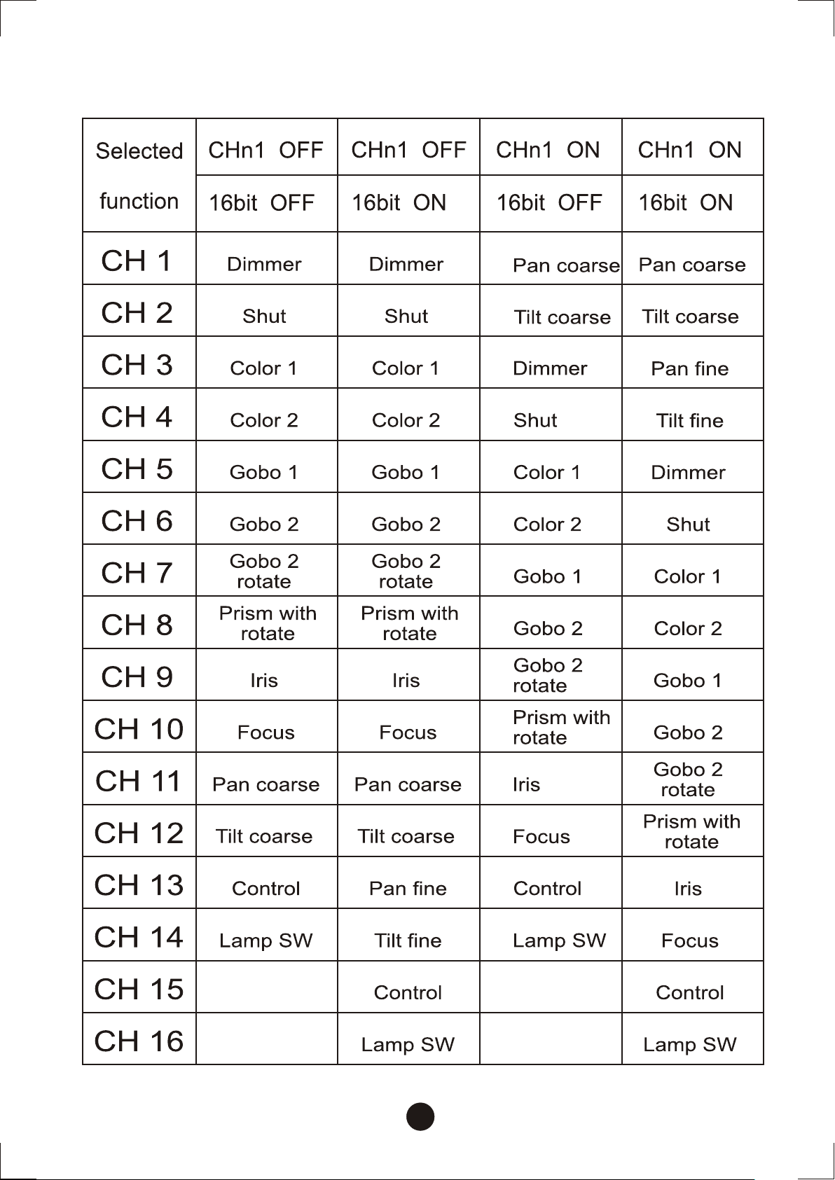
Channels arrangement
13
Page 16
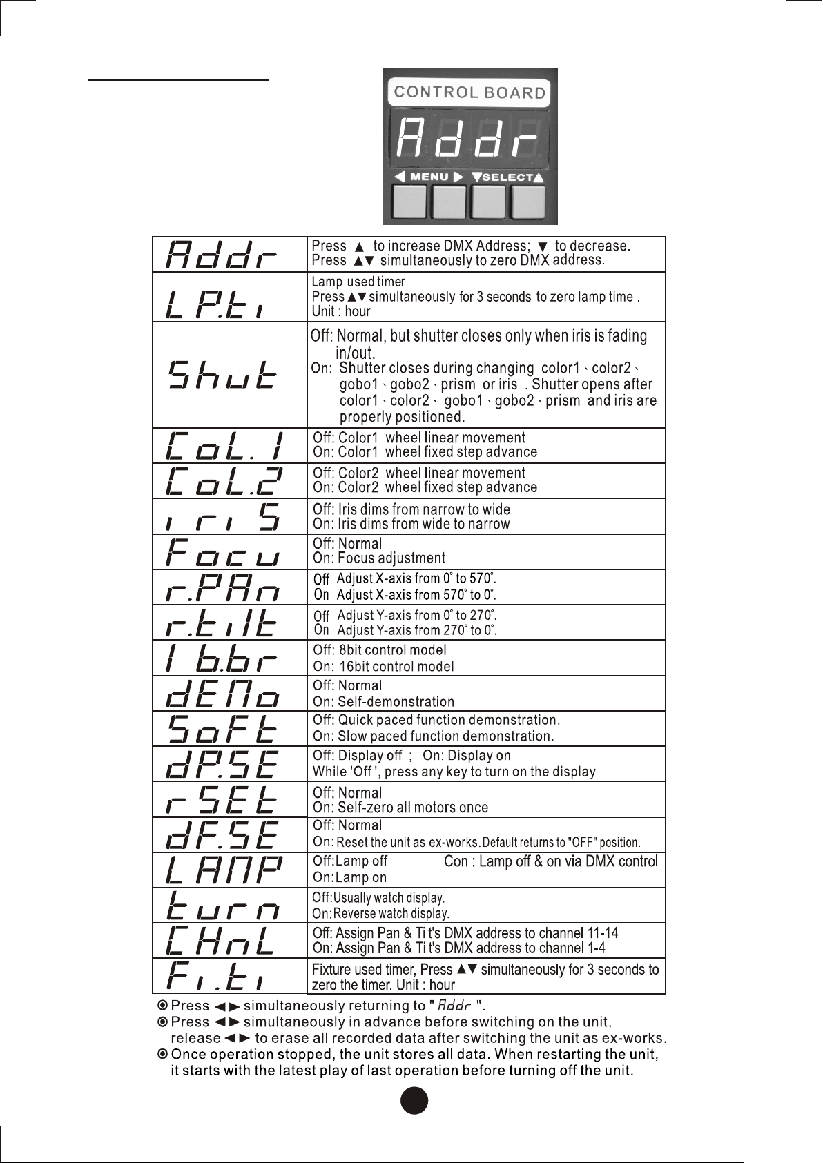
Control Board
14
Page 17
Maintenance
Refer maintenance to qualified technicians. Please disconnect power
and signal wire before maintaining fixtures.
In order to preserve OBY-5 in good condition, keep the routine
maintenance by following date.
The steps are as follows:
The dichroic colour-filters, the metal gobo-wheel, the internal lenses
and cooling fans should be cleaned with soft brush monthly.
The interior of the fixture should be cleaned at least half-yearly using
a vacuum-cleaner or an air-jet.
Caution: Be careful not to damage the interior mechanical structures
or circuits when using the air-jet.
To ensure a proper function and smooth rotation of the gobo-wheel,
we recommend lubrication in six-month intervals.
Caution: Avoid the damage of interior structures when fixtures
rotated, do not use excess lubrication.
Due to emit fog frequently, the optical lens and gobos would be oily;
thus luminosity would be weak. We recommend using moist cloth or a
trace of detergents to wipe them every two weeks. (Prohibit using the
detergents consisted of alcohol and solvents.)
15
Page 18
Replacing the Fuse
If the fixture does not function, that may be the fuse was burned out. It
may be time to replace the fuse of same type and specification for
eliminating this fault.
Remove the electric power and flip the switch to " off " position before
replacing the fuse.
Replace the fuse as follows:
Step 1: Unscrew the screw of the fuse holder on the housing
counterclockwise with appropriate tools.
Step 2: Remove the broken fuse and then replace the new fuse.
Step 3: Reinsert and tighten the screw on the fuse-holder.
Step 4: Turn the power on for test.
Please contact with the dealer if the fixture still cannot work or the fuse
burns out again.
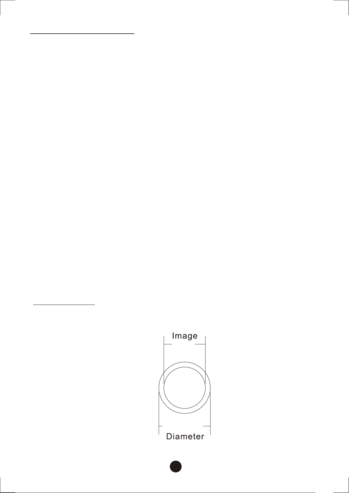
Appendix A
GOBO Size
25 m m
31 mm31 mm
16
Page 19
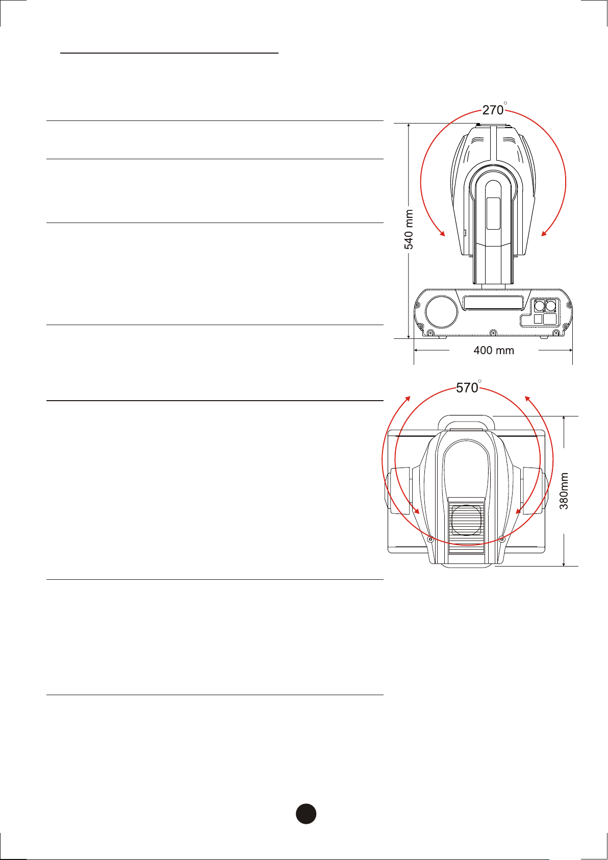
Product Specifications
Physical
Dimension(L × W × H): 400 × 380 × 540mm
Weight: 26kg
AC supply
AC input: Certified power cord with plug or without plug
Voltage: 220V, 230, 240V 50/60Hz: 100V,120V 50/60Hz
Fuse: AC 230V: 7A/250V AC 100V~120V:15A/250V
Power Consumption: 800W
Control and programming
Signal pinout: pin 1 shield, pin 2 (-), pin 3 (+)
Setting and addressing: LED control panel
Protocol: USITT DMX-512
Pan/tilt resolution: 8 or 16 bit
DMX channels: 14-16
Signal input: 3-pin XLR male
Signal output: 3-pin XLR female
Source
Lamp: 575W discharge
Base: SFC10-4
Approved models: Philips MSI-575/HR (1000 hr; 6000K)
Philips MSI-575/2 (1000 hr; 6500K)
Control: Automatic and DMX remote on/off
Electromechanical effects
Color wheel 1: 11 dichroic colors+white
Color wheel 2: 11 dichroic colors+white
Fixed gobo wheel: 9 replaceable gobos+white
Rotating gobo wheel: 6 replaceable gobos+white
Gobo rotation: adjustable speed and position direction
Dimmer: 0-100% linear dimmer
Strobe: 1-7Hz fast flashing
Rotating 3-facet prism: in/out variable speed and direction
Focus: 2m-infinity
Iris: Mini 4 -Max 15° °
Pan: 0 ~570° °
Tilt: 0 ~270° °
Wheel control: auto-electronic reset
Gobos
Metal gobo: Diameter:31 mm
Maximum image diameter:25 mm
Metal type:white iron
Glass gobo: Diameter:31 mm
Maximum image diameter:25 mm
Glass type:heat-resistant and intensify glass
Glass coating:dichroic
17
 Loading...