

Page 1
TM
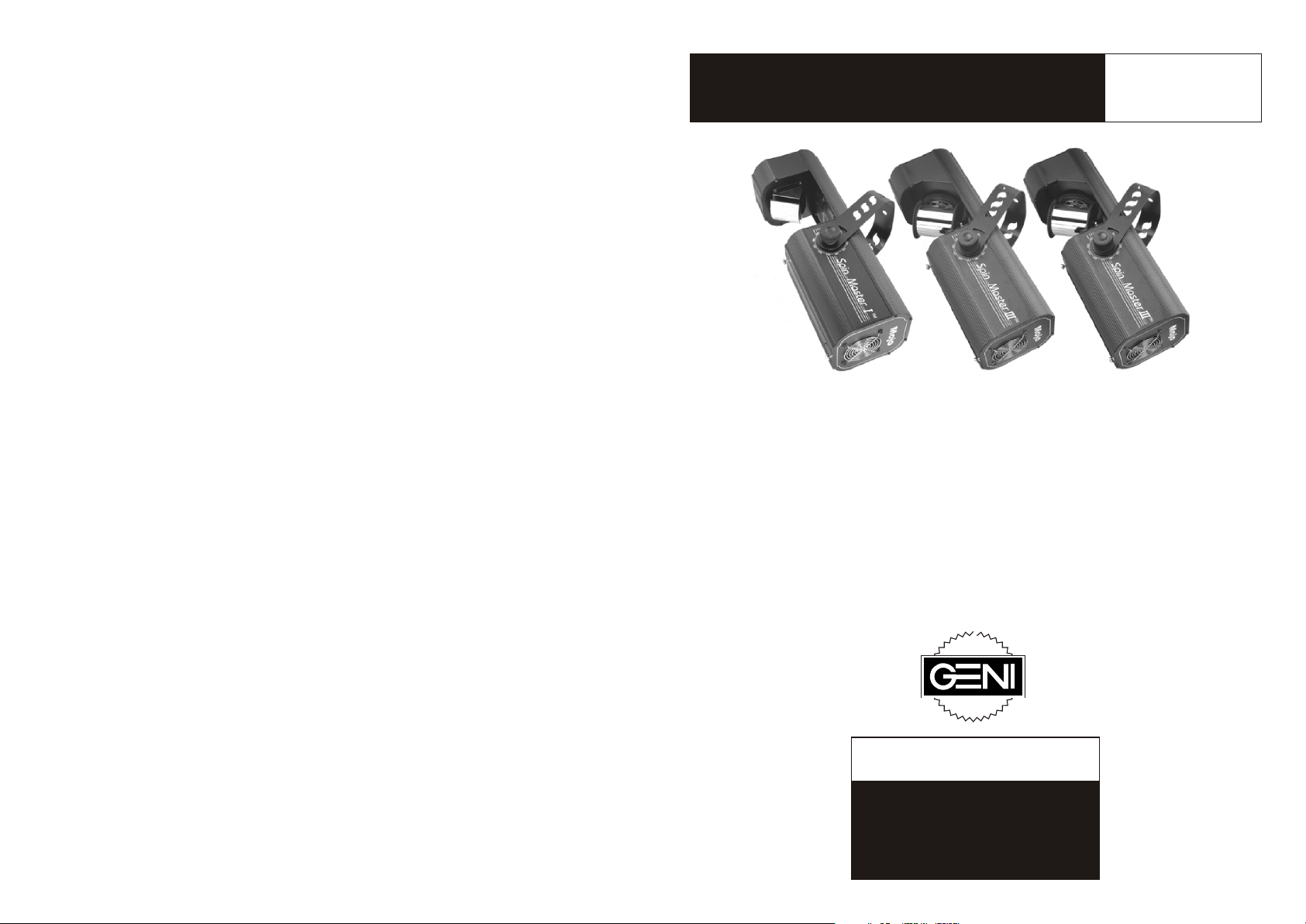
Mojo Spin Master
Product User
Guide to MJS1,
MJS2, MJS3
MJS-1 MJS-2 MJS-3
Mojo Spin Master light effects
TM
create an energetic whirl of colored images.
Spin Master I emits a wild, whirling vortex of images.
Spin Master II lines the dance floor with racing images.
Spin Master III sends viewers reeling - with a swerving,
TM
TM
TM
turning, unlimited movement, image ray effect.
ã
Copyright 2001 Geni Electronics Co., Ltd.
Product specifications may be subject to change.
For more information, please visit our web site:
http://www.geni.com.tw. Thank you!
Geni Electronics Co., Ltd.
THANK YOU!
Thank you for buying a Geni
product. For best results, please
carefully read and follow the
directions in this product user manual.
Page 2
Congratulations!
You have a great, innovative product from Geni Electronics Co., Ltd. Geni
Mojo Spin Master effect lights bring excitement to any venue. Whether you
want simple plug-&-play action or a sophisticated DMX show, this product
series provides the effect you need.
You can rely on Geni Electronics Co., Ltd., for more excellent lighting products.
We design and manufacture strobes, effects, and mirrored projectors. And
new products are being launched regularly. For information, please visit our
web site at http://www.geni.com.tw. We work hard to keep you, our customer,
satisfied.
You can get some of the best quality, best priced products on the market from
Geni. So next time, turn to Geni for more great lighting equipment. Always get
the best -- with Geni.
TM
Appendix B - Back Panel
Mojo Series Product Back Panel
B
A
H
C
D
Mojo
E
G
F
A - Earth (Ground)
B - IEC power connector
C - Fuse holder
D - DMX signal Canon connector (IN)
E - DMX signal Canon connector (OUT)
F - Microphone
G - Product specification label
H - DMX and function dip switches
Thank you!
Geni Electronics Co., Ltd.
Main Office/Factory Address:
Geni Electronics Co., Ltd.
No. 22, Chung Cheng 5 Street
th
Yung Kang Tainan Hsien, Taiwan
Tel: 886-6-253-8513
Fax: 886-6-253-8685
Showroom Address:
Taipei World Trade Center, Room 3A-04
No. 5, Section 5, Hsin Yi Road
Taipei, Taiwan
Tel: 886-2-2722-2910 Get the Best - Get Geni
Fax: 886-2-2722-2918 Geni Sets the Standard
Note: For simplicity, the back panel of one Mojo product is shown.
Other product back panels may differ slightly.
Figure 4
12
Page 3

Appendix A - DMX Dip Switch Value Guide
DMX products must have their own "address" to receive DMX signals.
Addresses on Mojo series products are set by flipping appropriate DMX dip
switches.
Mojo Spin Master Product Guide
TM
This product user guide covers the following effect lights:
Mojo Spin Master I (MJS-1), Mojo Spin Master II (MJS-2), Mojo Spin
Master III (MJS-3).
TM
TM TM
To do this, you need to know that DMX dip switches have the following values:
#1=1; #2=2; #3=4; #4=8; #5=1; #6=32; #7=64; #8=128; #9=256. And you need
to know that DMX address settings are the sum of the dip switch values.
For example, standard DMX addresses for four Mojo Spin Master III effect
TM
lights, each of which has four channels (See page 10.), Follow:
MJS3 Address Value DMX Dip Switches "ON"
Unit 1 1 #1
Unit 2 5 #3 & #1
Unit 3 9 #4 & #1
Unit 4 13 #4, #3, #1
Explanation: Since each unit has four channels, each address advances four
values (See Address Value above).
Once address values are figured out, add DMX dip switch values to obtain the
appropriate address (DMX Dip Switches "ON") for each unit. Flip appropriate
DMX dip switches on each unit.
Description........................................................................................Page 1
Warning............................................................................................ Page 1
Getting Ready...................................................................................Page 2
Install the Lamp................................................................................ Page 2
Lamp Installation.............................................................................. Page 2
Installing the Lamp (Figure 1)...........................................................Page 2
Set Up and Operation.......................................................................Page 3
One-unit Audio Set Up .....................................................................Page 3
Four-unit Audio.................................................................................Page 3
Four-unit Audio Set Up (Figure 2).................................................... Page 4
DMX Control.................................................................................... Page 4
DMX Set Up(Figure 3)......................................................................Page 5
Product Operation Overview............................................................ Page 5
Function Dip Switch Chart................................................................Page 6
Mojo Spin Master I DMX Channel Chart........................................Page 6
Mojo Spin Master II DMX Channel Chart.......................................Page 7
Mojo Spin Master III DMX Channel Chart......................................Page 7
TM
TM
TM
Maintenance.....................................................................................Page 8
Changing the Lamp.......................................................................... Page 8
Replacing the Fuse.......................................................................... Page 8
Troubleshooting................................................................................Page 9
No Light, No Movement - All Products..............................................Page 9
No Response to DMX ......................................................................Page 9
No Response to Audio .................................................................... Page 9
Product Specifications......................................................................Page 10
Appendix A - DMX Dip Switch Value Guide.................................... Page 11
Appendix B - Back Panel (Figure 4)............................................... Page 12
11
Page 4
Description
Mojo Spin Master effect lights create an energetic whirl of colored images.
Mojo Spin Master I emits an energetic whirl of colored images. Spin Master
TM TM
II lines the dance floor with racing images. Spin Master III sends viewers
reeling -- with a swerving, turning, unlimited movement, image ray effect.
The set up, control, and functions of various Mojo Spin Master effect lights
may differ. Please refer to specific product headings in this manual.
TM
TM
TM
Product Specifications
Name: Mojo Spin Master I Name: Mojo Spin Master I
Model: MJS-1 Model: MJS-1
Voltage: 230V~50Hz (CE) Voltage: 120V~50/60Hz
Power consumption: 300W Power consumption: 300W
Fuse: T3.15A Fuse: T3.15A
Dimensions: 475x220x160 mm Dimensions: 475x220x160mm
Weight: 7.5 kg Weight: 7.5 kg
Lamp: GX5.3 24V/250W (ELC)* Lamp: GX5.3 24V/250W (ELC)*
TM TM
Warning!
Like all electronic products, Mojo Spin Master effect
lights must be used with common safety precautions
in mind.
! Mojo Spin Master effect lights contain no user-serviceable parts.
TM
Refer servicing to qualified technicians only.
! Disconnect from electric mains power supply before removing covers
or changing lamps. Keep case closed while operating. Do not insert
objects into air vents.
! Keep away from flames and flammable material. Keep away from
liquids. Never operate in rain or in damp conditions.
! If effect lights are dropped or struck, disconnect mains power supply
immediately. Have a qualified engineer inspect for safety before
operating.
! Lamp and metal become hot during operation. Allow time to cool
before handling. Do not touch lamp bulb glass with bare hands.
! Read user manual instructions thoroughly before operating. Follow the
instructions. Never remove warning or informative labels from the unit.
TM
Name: Mojo Spin Master II Name: Mojo Spin Master II
TM TM
Model: MJS-2 Model: MJS-2
Voltage: 230V~50Hz (CE) Voltage: 120V~50/60Hz
Power consumption: 300W Power consumption: 300W
Fuse: T3.15A Fuse: T3.15A
Dimensions: 475x220x160 mm Dimensions: 475x220x160mm
Weight: 7.8 kg Weight: 7.8 kg
Lamp: GX5.3 24V/250W (ELC)* Lamp: GX5.3 24V/250W (ELC)*
Name: Mojo Spin Master III Name: Mojo Spin Master III
TM TM
Model: MJS-3 Model: MJS-3
Voltage: 230V~50Hz (CE) Voltage: 120V~50/60Hz
Power consumption: 300W Power consumption: 300W
Fuse: T3.15A Fuse: T3.15A
Dimensions: 475x220x160 mm Dimensions: 475x220x160mm
Weight: 8.7 kg Weight: 8.7 kg
Lamp: GX5.3 24V/250W (ELC)* Lamp: GX5.3 24V/250W (ELC)*
*: Versions for other lamps may be produced. Please check the specification
label on your product.
Product specifications may be subject to change. Please visit
www.geni.com.tw for details.
1
10
Page 5
Troubleshooting
This troubleshooting guide is meant to help solve simple problems. If a
problem occurs, carry out the steps below in sequence until a solution is found.
Once the unit operates properly, do not carry out following steps. If the effect
does not operate properly, refer servicing to a technician.
No Light, No Movement - All Products
Response: Suspect three potential problem areas: the power supply, the lamp,
the fuse.
1. Power supply. Check that the unit is plugged into an appropriate power
supply.
2. The lamp. Replace the old lamp with a new one of appropriate
specifications. See directions above for replacing lamps.
3. The fuse. Replace the fuse. See directions above for replacing the fuse.
No Response to DMX
Response: Suspect the DMX dip switch setting, DMX cable or connectors, a
controller malfunction, a light effect DMX card malfunction.
1. Check the DMX dip switch setting. Make sure the DMX dip switch address
setting is correct.
2. Check the DMX cable: Unplug the unit; change the DMX cable; resupply
electrical power. Try your DMX control again.
3. Determine whether the controller or light effect is at fault. Does the controller
operate other DMX products properly? If not, take the controller in for repair.
If so, take the DMX cable and the light effect to a qualified technician.
No Response to Audio
1. Check the function setting of the first unit. Make sure that function dip switch
#1 is on. (Function dip switch #1 on = audio control.)
2. Turn up the music volume.
Getting Ready
All Geni products are thoroughly tested at the factory and shipped in perfect
condition. If damage has occurred during shipping or if components are
missing, please contact your Geni dealer immediately.
Your package should include:
(1) One Mojo Spin Master series lighting effect with bracket.
TM
(2) One IEC electric mains power cord with plug.
(3) One product user manual.
The lamp may or may not be included, depending on your Geni dealer. In most
cases, the lamp is not included.
Install the Lamp
Mojo Spin Master series effects use either the GX5.3 24V/250W lamp by
Osram or the ELC lamp of identical specifications by Philips. Use only the
appropriate lamp for your unit. Note that product versions that use other lamps
may be offered in the future. Check your product specification label for
information.
TM
Lamp Installation
(1) Loosen the two screws on the top of the lamp cover. Open the case.
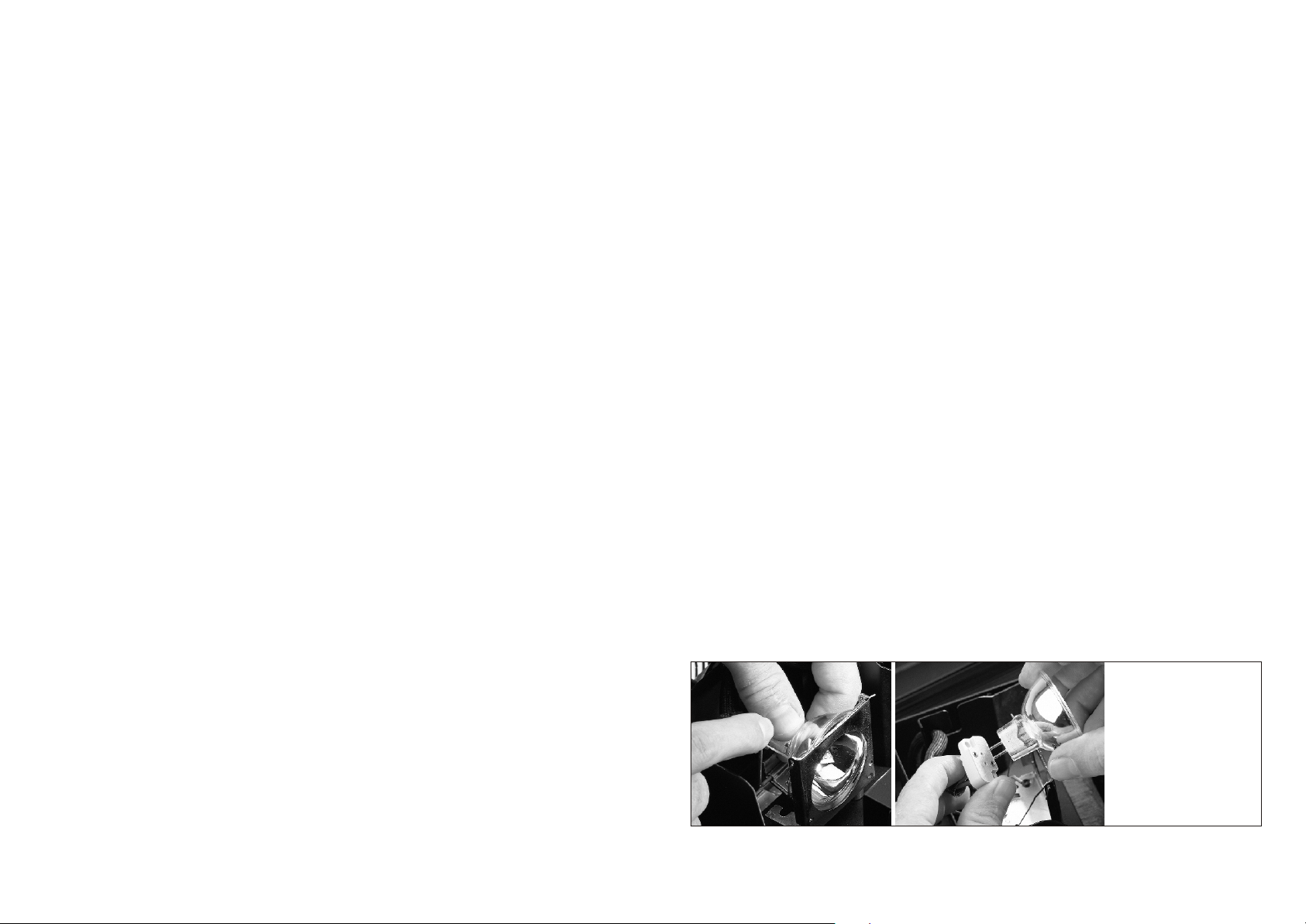
(2) Read lamp instructions. Do not touch the lamp bulb glass. (See Figure 1.)
Oil on hands shortens the lamp life. (If you touch the bulb glass, wipe off
the glass with a clean, lint-free towel and rubbing alcohol.)
(3) Hold the lamp socket with one hand. Insert the lamp pins into the holes in
the lamp socket.
(4) Make sure that the lever is up. Slide the lamp into the lamp base.
(5) Put on the lamp cover and fasten the screws snugly.
Lamp Items
B
A
C
D
A - Lever
B - "ELC" Lamp
E
C - Lamp Base
D - Lamp Socket
E - Lamp Pins
Figure 1
9
2
Page 6

Set Up and Operation
The set up and operation of all Mojo Spin Master light effects is similar. The
main difference is that function channels of various items vary, so that dip
switch settings differ slightly. Follow directions below as they pertain to your
particular product and your preferred operation mode.
Before plugging unit in, always make sure that the power supply matches the
product specification voltage. Do not attempt to operate a 120V specification
product on 230V power, or vice versa.
TM
One-unit Audio Effect
(1) Fasten the effect light onto firm trussing (Use a 30-kg rated or stronger Cclamp fastened onto the Mojo Moon bracket). Leave at least one meter on all
sides for air circulation.
(2) Flip "on" function dip switch #1 and regular dip switch #1.
(3) Plug one end of the electric mains power cord into the IEC socket on the
unit. (See figure 5, page 6.) Then plug the other end of the cord into a proper
electric power supply socket.
(4) Turn on the music. The effect will change to the music.
Four-unit Audio
1. Fasten the effect lights onto firm trussing (Use a 30-kg rated or stronger Cclamp bolted onto the Mojo Moon bracket). Leave at least one meter on all
sides for air circulation.
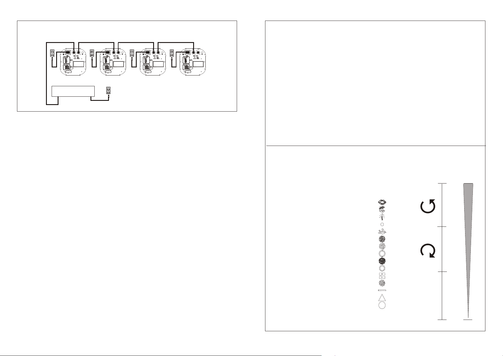
2. Link the units as shown in figure 2, page 4. Connect a DMX signal cable from
the first unit's DMX "out" socket to the second unit's "in" socket. Repeat this
process to link the second, third, and fourth units.
3. Activate audio control: On the first unit, flip "on" function dip switch #1.
Terminate the system: On the last unit, flip "on" function dip switch #2.
4. Set DMX dip switches as follows.
MJS1 Dip ON MJS2 Dip ON MJS3 Dip ON
Unit 1 #2 Unit 1 #2 Unit 1 #2
Unit 2 #3 Unit 2 #1 #2 Unit 2 #1 #3
Unit 3 #1 #2 #3 Unit 3 #1 #3 Unit 3 #1 #4
Unit 4 #2 #4 Unit 4 #1 #2 #3 Unit 4 #1 #3 #4
4. Supply electric power: Plug electric mains power cords into each unit's IEC
socket (see figure 4), then plug the other end of the mains power cord into
proper electric power supply sockets, starting with the first unit. Do not supply
Maintenance
Mojo Spin Master light effects require almost no maintenance. However,
you should:
! Keep the unit clean. Disconnect the mains power supply, then wipe the cover
with a damp cloth. Do not immerse in liquid. Wipe lens clean with glass
cleaner and a soft cloth. Clean internal components about once a year with a
light brush and vacuum cleaner. Do not use alcohol or solvents.
! Keep connections clean. Disconnect electric power, then wipe the DMX and
audio connections with a damp cloth. Make sure connections are thoroughly
dry before linking equipment or supplying electric power.
TM
Changing the Lamp
If electrical power is supplied and the lamp does not light, it may be time to
change the lamp. Follow directions below to do so.
1. Disconnect mains power supply. Loosen the two screws on the top of the
lamp cover. Open the cover.
2. With one hand holding the lamp reflector, pull down the lamp lever
(toward the base of the unit). (See figure 1.) The lamp will be pushed out
of the lamp base. Holding the lamp socket with one hand, pull the lamp
out of the lamp socket with the other.
3. Pull up the lamp lever (away from the unit base, toward the lamp cover).
4. Follow directions for installing a new lamp, page 2.
Replacing a Fuse
Power surges or inappropriate electrical power supply may cause a fuse to
burn out. If the fuse burns out, the product will not function whatsoever. If
this happens, replace the fuse as follows:
1) Unplug the unit from electric power source.
2) Insert a flat-head screwdriver into a slot in the fuse cover (C in figure 4).
Gently pry up the fuse cover.
3) Note two fuses: The replacement fuse is covered; The used fuse has both
ends exposed. Remove the used fuse. If brown or unclear, it is burned out.
4) Push the replacement fuse out of its cover, then insert the replacement fuse
into the holder where the old fuse was. Reinsert the fuse cover.
Products are packed with a replacement fuse. If your replacement fuse is
missing, a new one can be purchased at an electric appliance store. Be sure to
use a fuse of the same type and specification. See the product specification
label for details.
3
3
8
Page 7
DMX Set Up
Function Dip Switch Chart
DMX IN DMX OUT
Unit 1
DMX Controller
DMX OUT
DMX IN DMX OUT
MojoMojo Mojo Mojo
Unit 2
Note: Link all DMX cables and
set dip switches before con-
DMX IN DMX OUT
Unit 3
DMX IN DMX OUT
Unit 4
Figure 4
necting electric power.
Do not supply power before the whole system is set up and connected
properly.
6. Design your show according to your DMX controller functions. DMX
channel functions are shown on pages 9,10, 11.
Product Operation Overview
Mojo Spin Master products are easy to operate. In general, there are two
modes: audio and DMX. Activate audio mode by flipping function dip switch #1
"on" on the first unit. Allow for DMX control by leaving function dip switch #1
"off". Function dip switch #1 on the first unit determines the control mode.
Leave function dip switch #1 in the "off" position on all following units, in audio
and DMX modes.
In audio mode (function dip switch #1 "on"), choose various shows by flipping
regular dip switches on the first unit. For example, for a slow, four-unit audio
show, flip "on" function dip switch #1 on the first unit to activate audio mode,
then flip regular dip switches #2 and #6 "on" to activate a slow-paced, four-unit
audio show. (See the following Function Channel Chart.)
Do not activate audio dip switches on following units, but set their DMX
channels according to regular DMX procedures. (See Appendix 1 for an
introduction to DMX dip switch settings.)
One final note: Terminate all systems by flipping "on" the second function dip
switch on the last unit. This preserves clear signal transmission in both audio
and DMX modes.
TM
Dip OFF Mode ON Mode
#1 Single unit show mode Single unit audio show mode
#2 Single unit audio mode 4-unit audio show mode, master
#3 Single unit audio mode Self-test mode
#4 Single unit audio mode Single, slow show mode
#5 Single unit audio mode Focus assistance
#6 1- unit audio, mixed show Audio low BPM show mode
#7 1-unit audio, mixed show Audio high BPM show mode
#8 Single unit audio mode No program
#9 Single unit audio mode No program
Applies only when audio mode (function dip switch #1 "on") is activated.
Otherwise, these channels are DMX address setting dip switches.
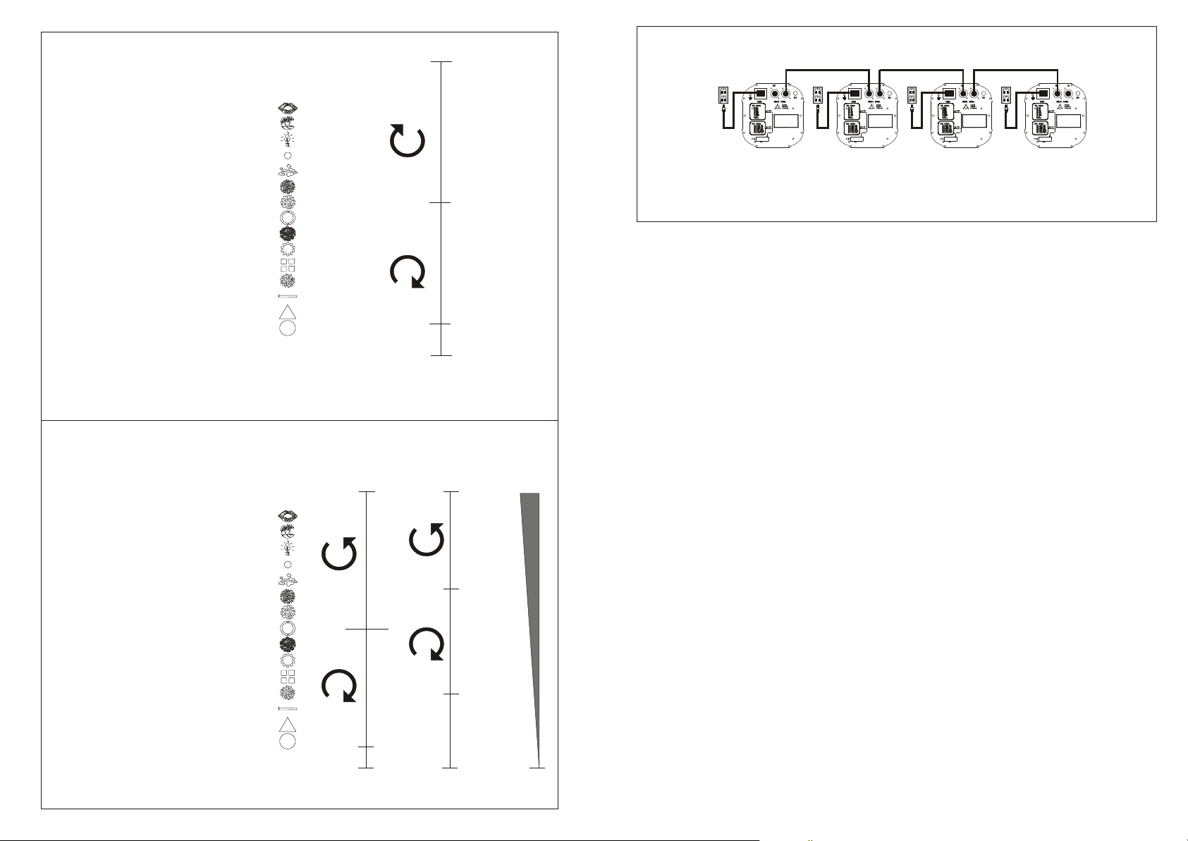
Mojo Spin Master I DMX Channel Chart
TM
CH1 - Effect CH2 CH3
209-255 Strobe - 1 flash per 4 seconds to 4fps 255 255
160-208 Rotation slow - fast slow
150-159 Red Lips (16)
140-149 Green Tropics (15)
130-139 Orange Candle (14) fast
120-129 White Roundlet(13) 184
110-119 White Clouds (12) 183
100-109 Blue Stars (11) fast
90-99 Purple Hearts (10)
80-89 Blue & Purple Arc (9)
70-79 Green Flowers (8) slow micro
60-69 Yellow Circle Ring (7) 112
50-59 Four-color Square (6) 111
40-49 Blue Bubbles (5)
30-39 Green, White, Yellow Bar (4) angle adjust-
20-29 Red Triangle (3) ment
10-19 White Circle (2)
0-9 Shutter (1) 0 0
0 Light unit automatically shuts off 5 seconds laters.
5
6
Page 8
Mojo Spin Master II DMX Channel Chart
CH 1 - Effect CH 2
209-255 Strobe- 1 flash per 4 seconds to 4 fps 255
160-208 Rotation slow - fast
150-159 Red Lips (16)
140-149 Green Tropics (15)
130-139 Orange Candle (14)
120-129 White Roundlet (13)
110-119 White Clouds (12)
100-109 Blue Stars (11)
90-99 Purple Hearts (10) 128
80-89 Blue & Purple Arc (9) 127
70-79 Green Flowers (8)
60-69 Yellow Circle Ring (7)
50-59 Four-color Square (6)
40-49 Blue Bubbles (5)
30-39 Green, White, Yellow Bar (4)
20-29 Red Triangle (3) 4
10-19 White Circle (2)
0-9 Shutter (1) 0-3 stop
0 Light unit automatically shuts off 5
seconds laters.
Mojo Spin Master III DMX Channel Chart
CH 1 - Effect
209-255 Strobe- 1 flash per 4 seconds to 4 fps
160-208 Rotation slow - fast
150-159 Red Lips (16)
140-149 Green Tropics (15)
130-139 Orange Candle (14)
120-129 White Roundlet (13)
110-119 White Clouds (12)
100-109 Blue Stars (11)
90-99 Purple Hearts (10)
80-89 Blue & Purple Arc (9)
70-79 Green Flowers (8)
60-69 Yellow Circle Ring (7)
50-59 Four-color Square (6)
40-49 Blue Bubbles (5)
30-39 Green, White, Yellow Bar (4)
20-29 Red Triangle (3)
10-19 White Circle (2)
0-9 Shutter (1)
0 Light unit automatically shuts off 5
seconds laters.
TM
CH 2 CH 3 CH 4
255
128
127
4
0-3 STOP
255
slow
Fast
184
183
Fast
slow
112
111
angle
0
255
micro
adjustment
0
Four-unit Audio Set Up
DMX IN DMX OUT DMX IN DMX OUT DMX IN DMX OUT DMX IN DMX OUT
MojoMojo Mojo Mojo
Unit 1
Unit 2
Unit 3
Unit 4
Note:Link cables and set dip switches before connecting
electric power.
power before the whole system is set up and connected properly.
5. Turn on the music.
Note that up to 64 units can be connected and operated in audio mode. To do
so, flip on DMX dip switch #1 on the 5th, 9th, 13th, etc., unit. Then repeat
settings on following units, so 6th, 10th, 14th, etc., unit DMX settings = unit 2
settings: 7th, 11th, 15th, etc., Unit DMX settings = unit 3 settings; 8th, 12th,
16th unit settings = unit 4 settings.
Figure 2
DMX Control
1. Fasten the effect light onto firm trussing (Use a 30-kg rated or stronger C clamp bolted onto the Mojo Spin Master bracket). Leave at least one
meter on all sides for air circulation.
2. Link the units as shown in Figure 3. Plug a DMX signal cable from the
controller to the first unit's DMX "in" socket. Then plug a DMX signal cable
from the first unit's DMX "out" socket to the second unit's "in" socket.
Repeat this process to link following units.
3. Set DMX dip switches as follows.
MJS-I Dip ON MJS-2 Dip ON MJS-3 Dip ON
Unit 1 #1
Unit 2 #3
Unit 3 #1#2#3
Unit 4 #2#4
Unit 1 #1
Unit 2 #1#2
Unit 3 #1#3
Unit 4 #1#2#3
For more units, continue to use standard DMX dip switch settings. See
Appendix 1 for details.
4. On the last in a series of units, flip "on" the Terminate dip switch (function
dip switch #2). This keeps the signal clear. Make sure other function dip
switches are "off".
5. Supply electric power: Plug electric mains power cords into each unit's IEC
socket (see figure 5), then plug the other end of the mains power cord into
proper electric power supply sockets. Do so for all units and the controller.
TM
Unit 1 #1
Unit 2 #1#3
Unit 3 #1#4
Unit 4 #1#3#4
7 4
 Loading...