

Page 1
TMTM
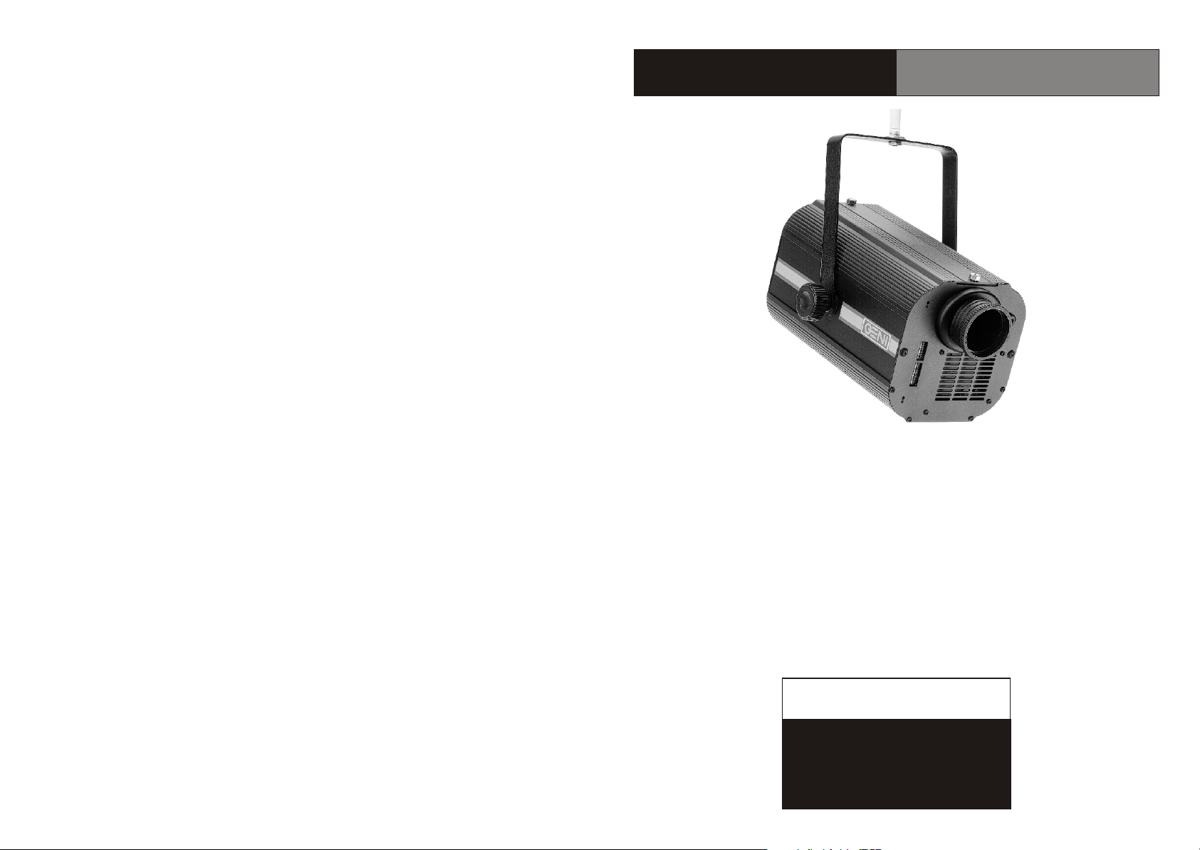
Color Blaster
Compact case, outstanding output,
Color Blaster color changer gets it right.
Color Blaster delivers a broad, strong beam of light;
Ten dichroic colors, + white, rainbow effect,
TM
TM
strobe and dimming.
CB-250/B/T
CAUTION!
Risk of electric shock
Read instructions before installing
or connecting to power
Page 2

Page 3
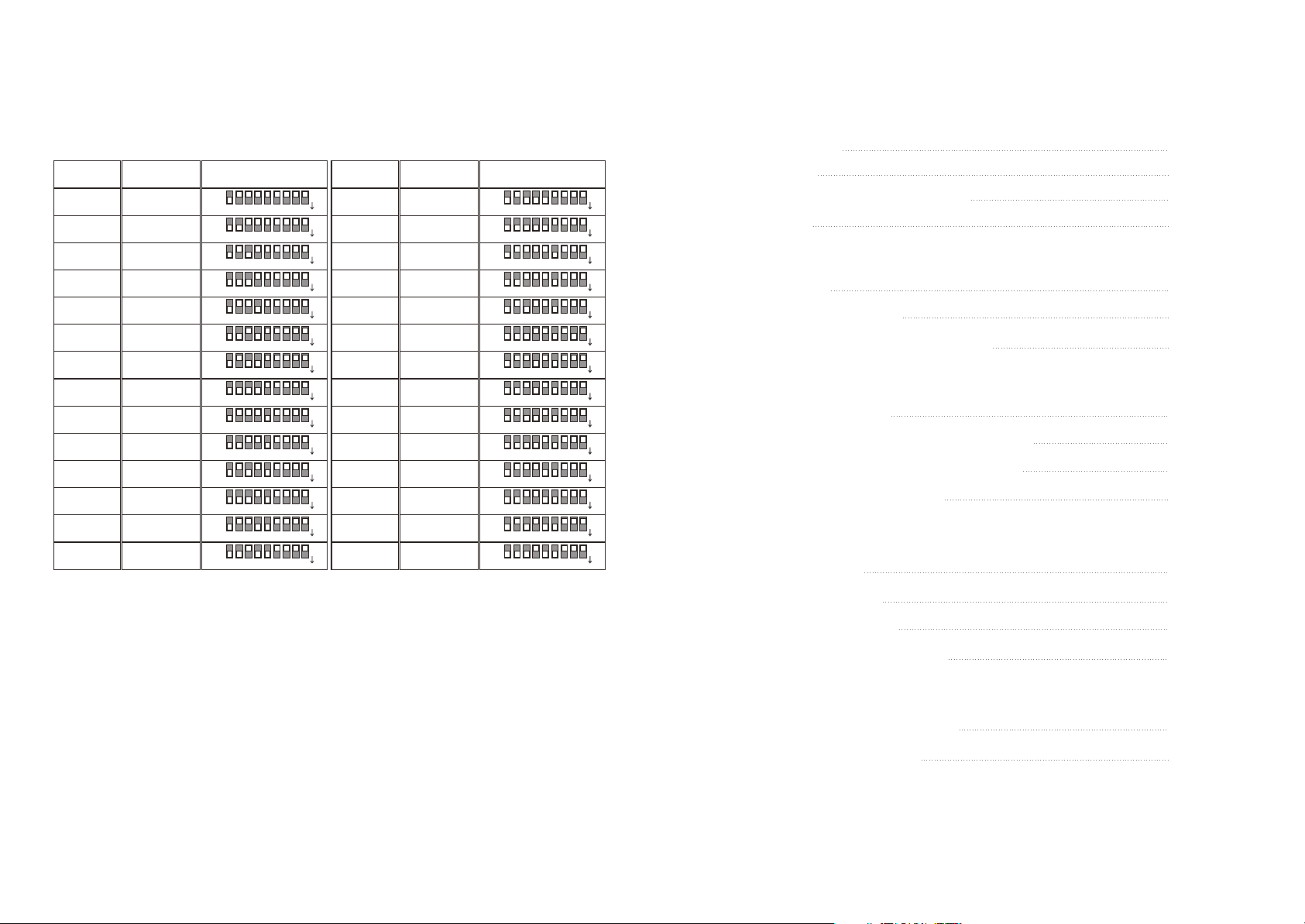
DMX Address Chart
DMX starting addresses and dip switch settings for 28 Color Blaster color
changers follow. For more information about the DMX512 addressing
system, please see the guide DMX512 Basics.
Unit
Unit 1
Unit 2
Unit 3
Unit 4
Unit 5
Unit 6
Unit 7
Unit 8
Unit 9
Unit 10
Unit 11
Unit 12
Unit 13
Unit 14
Address
1
3
5
7
9
11
13
15
17
19
21
23
25
27
Dip Switches
O
N
2 1
O
N
2 1
O
N
2 1
O
N
2 1
O
N
2 1
O
N
2 1
O
N
2 1
O
N
2 1
O
N
2 1
O
N
2 1
O
N
2 1
O
N
2 1
O
N
2 1
O
N
2 1
7
6 5
3
3
3
3
3
3
3
3
3
3
3
3
3
3
8
4
7
6 5
8
4
7
6 5
8
4
7
6 5
8
4
7
6 5
8
4
7
6 5
8
4
7
6 5
8
4
7
6 5
8
4
7
6 5
8
4
7
6 5
8
4
7
6 5
8
4
7
6 5
8
4
7
6 5
8
4
7
6 5
8
4
9
9
9
9
9
9
9
9
9
9
9
9
9
9
Unit
Unit 15
Unit 16
Unit 17
Unit 18
Unit 19
Unit 20
Unit 21
Unit 22
Unit 23
Unit 24
Unit 25
Unit 26
Unit 27
Unit 28
Address
29
31
33
35
37
39
41
43
45
47
49
51
53
55
Dip Switches
O
N
2 1
O
N
2 1
O
N
2 1
O
N
2 1
O
N
2 1
O
N
2 1
O
N
2 1
O
N
2 1
O
N
2 1
O
N
2 1
O
N
2 1
O
N
2 1
O
N
2 1
O
N
2 1
TM
9
7
6 5
3
3
3
3
3
3
3
3
3
3
3
3
3
3
8
4
9
7
6 5
8
4
9
7
6 5
8
4
9
7
6 5
8
4
9
7
6 5
8
4
9
7
6 5
8
4
9
7
6 5
8
4
9
7
6 5
8
4
9
7
6 5
8
4
9
7
6 5
8
4
9
7
6 5
8
4
9
7
6 5
8
4
9
7
6 5
8
4
9
7
6 5
8
4
Contents
Color Blaster
Description
Features
Color Changer Diagrams
Warning
Section 1 - Setting Up
Inspection
Lamp Installation
Color Changer Installation
Section 2 - Operation
DMX512 Control
DMX Channel Control Diagram
Audio Control for 4 or 8 Units
Function Dip Switches
Section 3 - General Use
Maintenance
TM
Page 1
Page 1
Page 2
Page 3
Page 3
Page 4
Page 5
Page 6
Page 7
Page 8
Page 9
Page 10
15
Lamp Removal
Trouble-shooting
Product Specifications
Appendix 1
Setting DMX Addresses
DMX Address Chart
Page 10
Page 11
Page 13
Page 14
Page 15
Page 4
Color Blaster
TM
Appendix 1
Description
A compact, powerful color changer, Color Blaster delivers a broad, strong
beam of colored light. You get ten dichroic colors + white, along with 1 to 5
frequency-per-second strobe and 0 to 100% dimming. Either turn on the
music to enjoy a preprogrammed audio-controlled show or use DMX
control. Both are chosen simply with the flip of a dip switch.
User-oriented design lets you work at your convenience. User aids
include focus assistance, selection of a four- or eight-unit audio program,
self-test function, and DMX signal termination.
Use Color Blaster color changer as a companion to Nimbus or Shiva
TM
series scanners, or make a powerful color show with Color Blaster alone.
With Color Blaster , you get a reliable, easy-to-use color changer that's
TM
value-engineered to serve you for years to come.
TM
TM
TM
TM
Features
High lumen output: large optical path
AR & IR coated lenses, high quality optics
Effect variety: Ten dichroic colors + white
Rainbow effect; shutter and dimming
Engineered to perform:
Electronic dimming 0-100%
Up to five frequency-per-second (fps) strobe
Audio and DMX512 control
Self-test and focus assistance functions
Powerful fan for efficient cooling
Built for lasting value:
One precision, quality stepper motor
Convenient to use:
Two preprogrammed audio-controlled shows
Standard DMX512 control and address
Convenient 3-pin XLR signal connection
Two channels: color/shutter; dimmer
Built-in focus assistance and self-test functions
1
Setting DMX Addresses
To set DMX addresses, you must know about (1) the relationship between
DMX512 dip switches and address values, (2) your equipment, and (3) how to
compute DMX addresses. The following is a brief explanation of the DMX512
system. For a more thorough guide, please see the booklet DMX512 Basics.
1. The relationship between DMX512 dip switches and address values:
Dip
Switch
Value DMX
1
1
2
2
3
4
4
8
5
1
6
32
N ote th at DMX values double progre ssiv ely: the fir st D MX dip sw itc h has a
DM X addre ss valu e of 1; Th e secon d DM X d ip switc h h as a valu e of 2; th e
thi rd DM X d ip swit ch h as a valu e of 4, etc ., as show n above.
2. Your equipment. Since each Color Blaster colo r change r ha s two DM X
TM
channe ls, ea ch starti ng address es advanc es tw o place s. I n th is example ,we
ha ve no oth er DM X equipme nt in fro nt of o ur co lor change rs, so the first
effe ct un it's starti ng addre ss shou ld = 1; Th e secon d uni t's startin g addre ss
shou ld = 3, e tc. L ist t he DM X starti ng valu es th at yo ur equipme nt sho uld
have.
3. Set DMX dip switches to appropriate DMX starting addresses . Begin wit h
t he highe st di p switc h valu e possibl e and wor k down from there . Fo r a DMX
startin g addre ss of 1 9, f or examp le, activ ate D MX dip sw itch #5 (w ith a
valu e of 16 ), the n wo rk dow n, activatin g d ip switc h #2 , (wi th a valu e o f 2 ),
an d d ip switc h # 1 (wit h a valu e o f 1 ). Us e a ballpoin t pe n o r a toothpic k to
fl ip DM X d ip switch es to th e appropria te addre ss settings.
For c onvenience, C olor B laster color change r startin g address es f or 28
TM
units and corresponding DMX dip switch settings are shown on the following
page.
6
7
6
4
8
128
9
256
14
Page 5
Product Specifications
Model: CB-250
Voltage: 120V~60Hz input
Lamp: 82V/250W EXY GX5.3 (200-hr)
Dimensions: 280x150x155mm (LxWxH)
Weight: 3.35 kg
Power consumption: 300VA
Signal: USITT DMX512
Signal connection: 3 pin XLR
Addressing: Standard DMX512 9-pin binary
Channels: 2 Fuse: T5A/250V 20mm
Termination: Built-in (manual)
Model: CB-250B
Voltage: 120V~50Hz; 230V~50Hz(CE Approved)
Lamp: 24V/250W EHJ G6.35 (No: 64655, 50-hr.; No: 64657 300-hr)
Dimensions: 280x150x155mm (LxWxH)
Weight: 5.70 kg
Power consumption: 300VA
Signal: USITT DMX512
Signal connection: 3 pin XLR
Addressing: Standard DMX512 9-pin binary
Channels: 2 Fuse: T5A/250V 20mm
Termination: Built-in (manual)
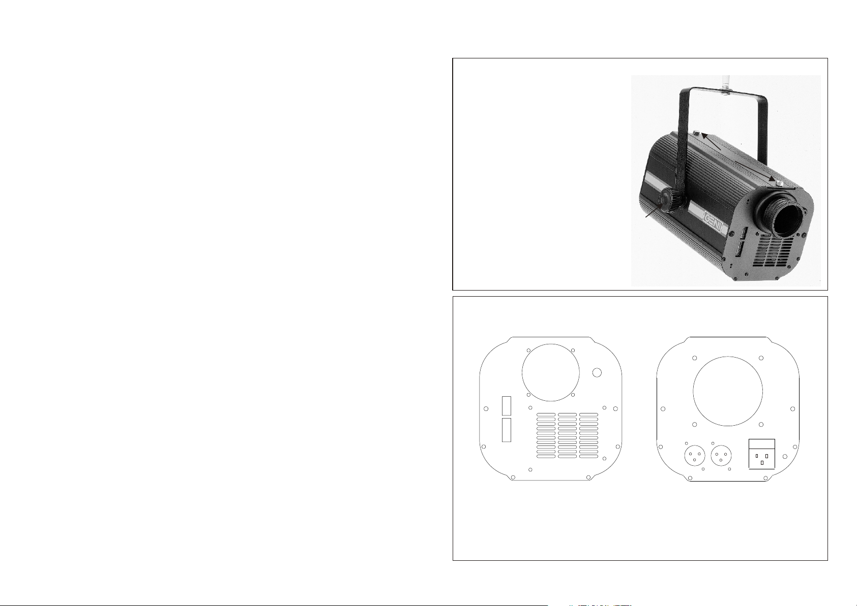
Color Changer Diagrams
Three-dimensional Diagram
T1 - Bracket
T2 - Unit Cover
T3 - Cover Screws
T4 - Bracket Knob
T4
Front and Back Views
Front
F1
F2
T1
T2
T3
Back
B1
Model: CB-250T
Voltage: 120V~50Hz; 230V~50Hz(CE Approved)
Lamp: 24V/250W ELC GX5.3 (50-hr)
Dimensions: 280x150x155mm (LxWxH)
Weight: 5.70 kg
Power consumption: 300VA
Signal: USITT DMX512
Signal connection: 3 pin XLR
Addressing: Standard DMX512 9-pin binary
Channels: 2 Fuse: T5A/250V 20mm
Termination: Built-in (manual)
13
F3
F4
F1 - Lens
F2 - Built-in Microphone
F3 - Function Dip Switches
F4 - DMX512 Dip Switches
F5 - Air Vents
F5
B4
B3
B1 - Fan Hole
B2 - Fuse Holder
B3 - Canon XLR Socket (DMX in)
B4 - Canon XLR Socket (DMX out)
B5 - Mains IEC Power Socket
B2
B5
2
Page 6
Warning!
Follow standard precautions for all electronic products.
This appliance must be earthed (grounded). Disconnect from
power before removing covers or servicing. Keep case closed while
operating.
Color Blaster color changer contains no user serviceable parts.
Servicing must be conducted by qualified service personnel.
Lamp and components become hot during operation. Allow time to
cool before handling.
Keep flammable material at least one meter away from unit. Do not
operate in wet conditions or near liquids.
Keep air vents clear to avoid overheating. Never insert objects into
air vents.
Lamp produces hazardous UV light. Do not look directly at lamp
when lit. Do not expose skin to uncovered lamp.
If objects fall on unit, disconnect mains power supply immediately.
Have a qualified technician inspect for safety before operating.
Never remove warning or informative labels from the unit.
TM
Problem: Function dip switches have been set for "audio mode," but color
changer does not respond to music.
Solution:
1. Disconnect power. Turnon Function dip switch #1. Turn off other
Function dip switches. Disconnect DMX signal cables. Reconnect
power supply. Turn on music.
2. Have a qualified service technician inspect the PC board.
Problem: Color changer light does not dim according to DMX slider positions.
Solution:
1. Have a qualified service technician inspect the unit, including Triac
41600.
Section 1 - Setting Up
Inspection
Every Color Blaster color changer was thoroughly tested and shipped in
perfect condition. Carefully unpack your Color Blaster color changer and
remove the bag with components from the carton. Inspect equipment for
shipping damage. If shipping damage has occurred, contact your Geni dealer
immediately.
Packing list:
1. Color Blaster color changer
2. IEC power cord
3. Operating manual
3
TM
TM
TM
12
Page 7

Trouble-shooting
Lamp Installation
The following tips are provide d t o he lp use rs so lve mi nor proble ms. Alw ays
refer servicing to qualified technicians.
Problem: Lamp is not lit and fan (B1) is not spinning.
Solution:
1. Check for proper power connection and supply.
2. Disconnect power supply. Use a flat-head screw driver to pr y open th e
fuse holder (B2) above the IEC power socket (B5). Check the fuse. If the
fuse is discolo red, rathe r than clear, replace it. A replac ement fuse is
provided in the fuse holder. Always use appropriate type of fuse.
Problem: Lamp is not lit, but fan is operating.
Solution:
1. Disconnect power (D5). Let unit cool. Check t he l amp. I f lamp is
discolored or broken, r eplace i t w ith a n ew la mp o f th e a ppropriate ty pe.
2. If lamp is not burnt or broken, re-insert it. If you accidentally touch
the lamp bulb with your bare hands, wipe the bulb clean with a lint-free
clo th.
3.
Close the case ( 2), tighten case screw s (T3) , an d reconnec t powe r. If
T
unit still doesn't operate properly , refe r servicing t o a qualifie d servic e
technician.
Problem: Colors don't change according to DMX512 slider positions.
Solution:
1. Check DMX512 dip switch setting s (F4 ). Mak e su re un it is address ed
properly. Make sure that Function dip switches (F3) 1-5 and 7 are off.
2. Turn on self-test function, Functio n d ip swi tch # 3 . If unit ope rates
properly, replace the original DMX signal cable with a good cable.
3. Have a qualified service technician check the unit, including the stepper
motor and its driver, IC 2069.
Caution! Lamp and metal components get hot during operation. Always
disconnect power and allo w un it to co ol befo re chang ing lam p s or open ing
unit cover.
Note: There are thre e type s of Co lor Blas t e r co lor chang ers, e ac h of which
TM
uses a different lamp. Be sure to use the proper lamp for your unit.
CB-250
designed
is
for
is
there where use
power 120V~50/60Hz
uses EXY 93510 GV5.3 82V/250W (200-hour) lamp. This lamp is sometimes
referred to as a "cup lamp" because the bulb is in the center of a cup-shaped
reflector.
CB-250B
is
or 120V~50/60Hz is there where use for designed
230V~50/60Hz power supply. It uses EHJ 64655 G6.35 24V/250W
(50hour) or EHJ 64657 G6.35 24V/250W (300-hour ) lamp . This lamp slip s
into the center of a reflector plate that is built into the unit.
CB-250T
is
or 120V~50/60Hz is there where use for designed
230V~50/60Hz power supply. It uses HLX 64653 ELC 24V/250W (50-hour)
lamp. Like the lamp of CB-250, this lamp is a "cup lamp."
Follow lamp installation instructions for your specific product. Always
disconnect from power source before opening cover or servicing.
CB-250B
1. Loosen the two screws (T3) on the unit cover (T2). Remove cover (T2).
2. Remove lamp from packaging. Read lamp instructions. Grasp the lamp
stem, not the lamp bulb glas s. Touching the glass with bare hands can shorten
the lamp life. (Lamp not included with Color Blaster color changer.)
TM
3. Cover the lamp bulb glass with a lint-fre e clot h o r pape r. Ho ld th e covere d
bulb in one hand and inser t the lamp stem through th e hol e i n th e reflector
cup.
4. With your other hand, guide the lamp pins into the holes in the lamp socket.
Insert firmly.
5. Replace unit cover (T2) and fasten screws (T3) firmly.
It supply.
11
4
Page 8

CB-250 and CB-250T
1. Loosen the two screws (T3) on the unit cover (T2). Remove the cover.
2. Remove lamp from pa ckaging. Read lamp instructions . Do not touc h lam p
bulb with bare hands, as this could damage the lamp. (Lamp not included with
Color Blaster color changer.)
3 Holding the lamp reflector cup in one hand and the lamp socket in the other,
.
insert the lamp pins into the holes in the lamp socket.
4. Slide the reflector cup fully down into the lamp holder. The lamp lever will
move forward.
5. Replace unit cover (F2) and fasten screws (F3) firmly.
TM
Section 3 - General Use
Maintenance
Warning: Disconnect power and let unit cool before handling. Never open uni t
when in use. Keep away from water and other liquids.
To maintain maximum brightness, clean the unit regularly with a damp cloth o r
glass cleaner. Do not use alcohol or solvents.
1. Wipe lens clean regularly.
2. Keep internal optical path free from dust or cobwebs.
3. Clean internal parts once a year with a brush and strong vacuum cleaner.
Color Changer Installation
Follow the steps below to install Color Blaster color changer.
1. Use a 12-kg rated or stronger clamp to fasten Color Blaste r color changer
bracket (T1) onto a good t russ. A llowo ne m eter o n a ll si desfo r pr oper co oling.
Keep unit away from liquids a nd f lammable i t ems. A djust t il t a n d tig hten
bracket knob (T4).
2. "Daisy chain" the color changers as illustrated in DMX Basics. Always use
h igh q uality, t wisted p air1 20 o hm sh ielded, 22 or 24 AW G, bra ided shi eld
microphone cables and three-pin canon XLR connectors.
3. Set Function dip switch #6. Flip the dip switch as appropriate with either a
toothpick or ballpoint pen.I n a reas w ith 5 0 H z p ower su pply, tu rn Fu ction dip
switch #6 off. In areas with 60 Hz power, turn Fuction dip switch #6 on.
4. Use appropriate power supply for your unit. Plug mains power supply cord
into the unit's mains IEC power s ocket ( B5), t hen p lug o ther e nd in to
appropriate power supply socket.
5. Adjust focus. First, turn on Function dip (F3 ) switc h #4 : a whi te sp ot w ill
appear, then rotate lens until a good focus is obtained.
TM
TM
Lamp Removal
Disconnect power, let unit cool, then follow the directions below for your
specific product.
CB-250B
1. Loosen the two screws (T3) on the unit cover (T2). Remove cover (T2).
2. With one hand on the lamp socke t, pu ll th e lam p stem awa y from th e lam p
sock et.
3. Dispose lamps properly. Keep old lamps away from children and animals.
CB-250 and CB-250T
1. Loosen the two screws (T3) on the lamp cover (T2). Remove cover (T2).
2. Note that the lamp holder assembly includes a lever. While holding the
cup-shaped lamp reflector in one hand, pull the lever toward the back of the
unit.
3. With one hand holding the lamp socket, gently pull the cup-shaped lamp
reflector stem out of the lamp socket.
4. Dispose lamps properly. Keep old lamps away from children and animals.
5
10
Page 9
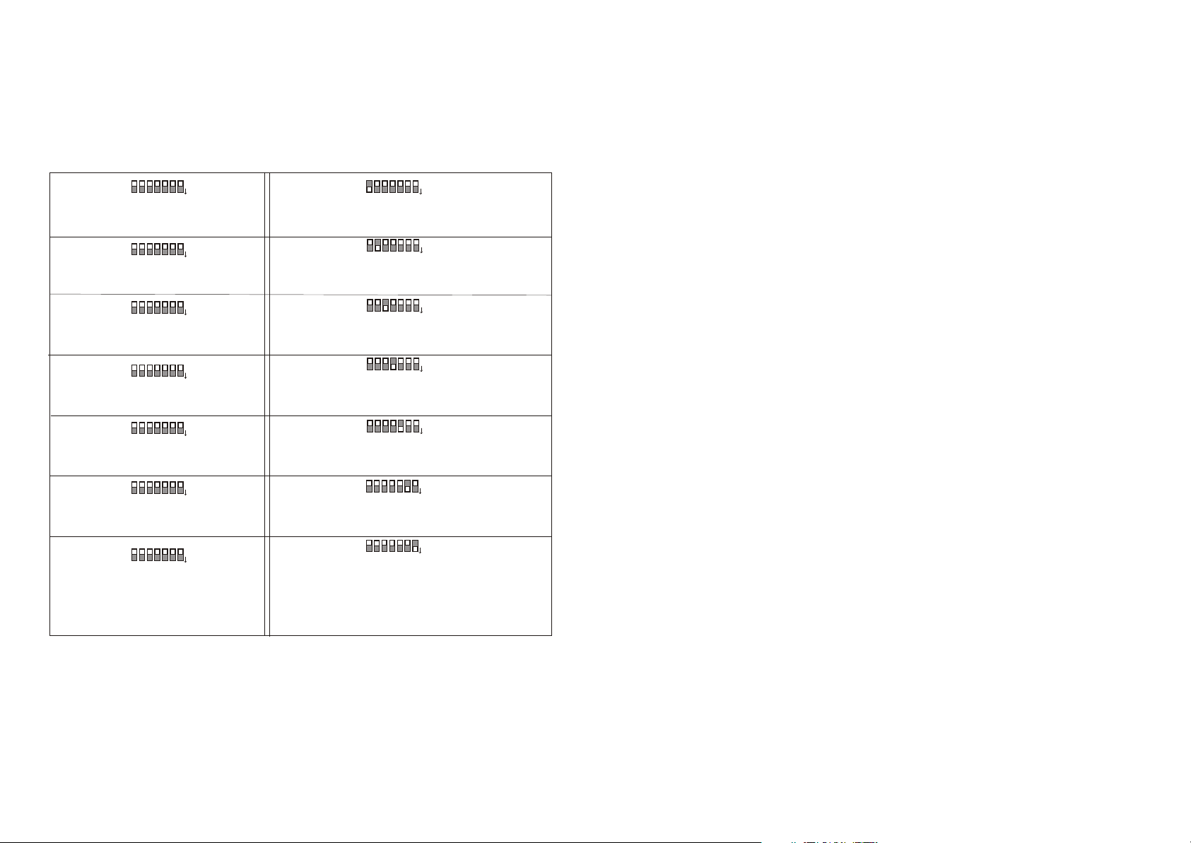
Function Dip Switches
The following functions are designed to enhance user convenience. Simply flip
the appropriate function dip switch as shown to activate the desired function.
Function Dip Switch Chart
O
#1 Off
O
2 1
2 1
5
5
7 6
4 3
7 6
4 3
N
N
Activates DMX controller mode
O
#2 Off
O
2 1
2 1
5
5
7 6
4 3
7 6
4 3
N
N
Activates DMX controller mode
O
#3 Off
O
2 1
2 1
5
5
7 6
4 3
7 6
4 3
N
N
Activates DMX controller mode
O
#4 Off
O
2 1
2 1
5
5
7 6
4 3
7 6
4 3
N
N
Activates DMX controller mode
O
#5 Off
O
2 1
2 1
5
5
7 6
4 3
7 6
4 3
N
N
Activates DMX controller mode
O
#6 Off
O
2 1
2 1
5
5
7 6
4 3
7 6
4 3
N
N
50 Hz power supply
O
#7 Off
O
2 1
2 1
5
5
7 6
4 3
7 6
4 3
N
N
Normal DMX operation
#1 On
Activates 4-unit audio mode; Please
refer to the audio control section.
#2 On
Activates 8-unit audio mode; Please
refer to the audio control section.
#3 On
Activates self-test function; Unit runs
through a set pattern of actions.
#4 On
Activates focus assistance; A white spot
appears for easy focusing.
#5 On
Not presently used
#6 On
60 Hz power supply; Activate this dip
switch if you have 60 Hz power supply.
#7 On
DMX signal termination; Activate this on
the last unit in a series of DMX
equipment. This keeps the DMX signal
free from interference.
O
O
2 1
2 1
5
5
7 6
4 3
7 6
4 3
N
N
O
O
2 1
2 1
5
5
7 6
4 3
7 6
4 3
N
N
O
O
2 1
2 1
5
5
7 6
4 3
7 6
4 3
N
N
O
O
2 1
2 1
5
5
7 6
4 3
7 6
4 3
N
N
O
O
2 1
2 1
5
5
7 6
4 3
7 6
4 3
N
N
O
O
2 1
2 1
5
5
7 6
4 3
7 6
4 3
N
N
O
O
2 1
2 1
5
5
7 6
4 3
7 6
4 3
N
N
Section 2 - Operation
DMX512 Control
Each Color Blaster c olor c hanger h as t wo D MX c hannels. T he fi rst ch annel
controls strobe, rotation, and color. The second channel c ontrols d imming.
Please see the DMX Channel Position Diagram on t he n ext p age f or d etails.
Follow t he d irectionsb elow to u se a D MX512 co ntroller w ith C olor Bl aster
color changer.
1. Link DMX signal cables to each unit properly, plugging signa l cable
connectors into c anon c o nnectors (B 4 an d B5 ). (S e e the gui de DM X512
Basics for more information.)
2. Set DMX512 dip switches settings. Use a toothpick o r ballpoin t pe n t o fl ip
dip switches to the appropriate address. See DMX Basics f or i nformation. O r
use Appendix 1 as reference.
3. Activate Function dip switch #7 on the last in a series of units. This will k eep
the DMX signal clear.
4. Make sure that your power source and th e uni t's specifie d pow er volta ge
are the same. Plug power cords into colo r change r IE C sock et (B5 ), th en
connect effect units and controller to power source.
5. Please refer to the Color Blaster c olor c hanger D MX C hannel C ontrol
Diagr am for programming positions.
TM
TM
TM
Note: Your color changer power supply should be disconnected when you
adjust dip switches. Reconnect power supply after setting Function dip
switches.
9
6
Page 10
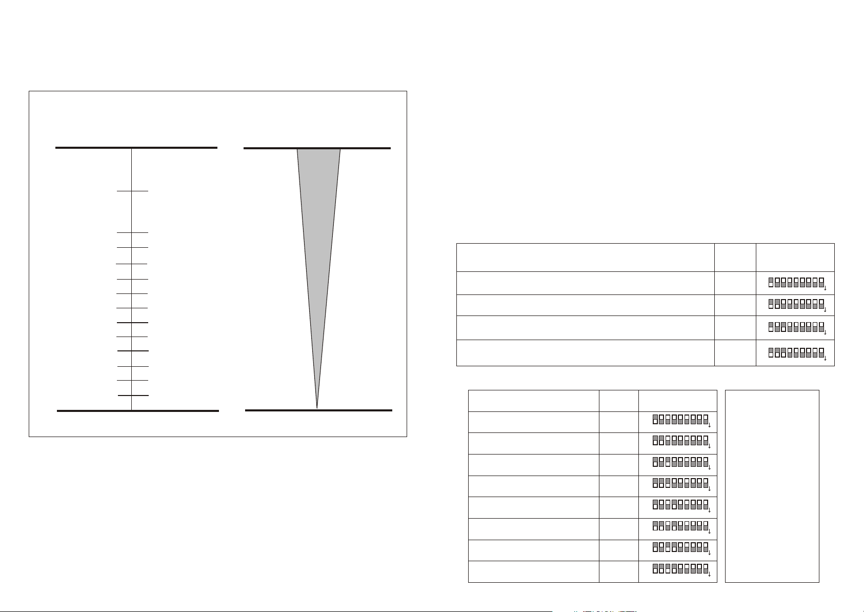
DMX Channel Control Diagram
Channel positions produce effects as indicated below.
Channel 2Channel 1
Color
Dimming
Audio Control for 4 or 8 Units
Color Blaster color changer has two sound activated show s i n memor y.
One show is for four units; the othe r is fo r eigh t units.
1. For an automatic, sound activated four-unit show, turn on Function dip
switch #1 of the first unit in the daisy chain. For an automatic, sound
activated eight-unit show, turn on Function dip switch #2 of the first unit in
the daisy chain. Turn on the music. The light show will begin.
TM
5 fps
255
Open
255
Strobe
1 fps
Fast
192
191
Rainbow
Slow
Light Pink
Blue Green
Dark Blue
Red
Green
Orange
Purple
Yellow
Lt. Blue
Pink
White
Off
141 - 153
128 - 140
116 - 127
103 - 115
154
90 - 102
77 - 89
64 - 76
52 - 63
39 - 51
26 - 38
13 - 25
0 - 12
Closed
128
0
For example, when using a DMX512 controller on channel one, from
position 103 to 115, a red-colored light will be projected. On channel two,
at position 255, light output will be on full power.
7
To operate more units on audio control, "double up" the DMX dip switch
addresses. For example, on the four-unit audio mode, the first, fifth, ninth,
and 13th units (etc.) would have the same DMX starting address value, 1.
And the second, sixth, tenth, (etc.) units would have the same dip switch
starting address value, 3. Refer to the diagram below for assistance.
Four-unit Audio Mode - DMX Dip Switch Settings
Color Changer Units
21,
17, 13, 9, 5, 1,
45 41, 37, 33, 29, 25,
3, 7, 11, 15, 19, 23, 27, 31, 35, 39, 43,47
Starting
Address
1
46 42, 38, 34, 30, 26, 22, 18, 14, 10, 6, 2,
3
5
748 44, 40, 36, 32, 28, 24, 20, 16, 12, 8, 4,
DMX Dip
Switches
O
O
2 1
2 1
N
N
O
O
2 1
2 1
N
N
O
O
2 1
2 1
N
N
O
O
2 1
2 1
N
N
8
8
9
9
5
5
7 6
4 3
7 6
4 3
8
8
9
9
5
5
7 6
4 3
7 6
4 3
8
8
9
9
5
5
7 6
4 3
7 6
4 3
8
8
9
9
5
5
7 6
4 3
7 6
4 3
Eight-unit Audio Mode - DMX Dip Switch Settings
Color Changer Units
1, 9, 17, 25, 33, 41
2, 10, 18, 26, 34, 42
3, 11, 19, 27, 35, 43
4, 12, 20, 28, 36, 44
5, 13, 21, 29, 37, 45
6, 14, 22, 30, 38, 46
7, 15, 23, 31, 39, 47
8, 16, 24, 32, 40, 48
Starting
Address
1
3
5
7
9
11
13
15
O
O
N
N
O
O
N
N
O
O
N
N
O
O
N
N
O
O
N
N
O
O
N
N
O
O
N
N
O
O
N
N
DMX Dip
Switches
2 1
2 1
5
5
4 3
4 3
2 1
2 1
5
5
4 3
4 3
2 1
2 1
5
5
4 3
4 3
2 1
2 1
5
5
4 3
4 3
2 1
2 1
5
5
4 3
4 3
2 1
2 1
5
5
4 3
4 3
2 1
2 1
5
5
4 3
4 3
2 1
2 1
5
5
4 3
4 3
Note: Up to
48 color
9
9
changers can
8
8
7 6
7 6
be operated
8
8
9
9
7 6
7 6
8
8
7 6
7 6
8
8
7 6
7 6
8
8
7 6
7 6
9
9
9
9
9
9
in the four-
unit or eightunit audio
modes, or in
DMX mode.
Keep DMX
cable length
8
8
9
9
7 6
7 6
8
8
7 6
7 6
8
8
7 6
7 6
within 100 meters
from the controller
9
9
to the last
color changer.
9
9
8
 Loading...