


User Manual
Routed Ethernet Gateway
OCG-218 / OCG-220 / OCG-2018 / OCG-2020
PRELIMINARY - JAN. 2011
Copyright © Genexis BV. All rights reserved 1

Table of Contents
Installation guide........................................................................................................3
Introduction...........................................................................................................................3
Product overview....................................................................................................................3
The front of the router............................................................................................................................3
...........................................................................................................................................................3
The side of the router.............................................................................................................................4
Installation.............................................................................................................................5
Getting started.......................................................................................................................7
Configuring the router (optional)...............................................................................................9
Troubleshooting....................................................................................................................10
Appendix: Router settings.........................................................................................11
Basic...................................................................................................................................11
Network Settings..................................................................................................................................11
Advanced ............................................................................................................................14
Virtual Server......................................................................................................................................14
Special Applications .............................................................................................................................15
Port Forwarding....................................................................................................................................16
Routing...............................................................................................................................................16
Access Control.....................................................................................................................................17
Website Filter.......................................................................................................................................17
Firewall Settings...................................................................................................................................18
Inbound Filter......................................................................................................................................20
Advanced Network................................................................................................................................21
Tools ..................................................................................................................................22
Administrator Settings..........................................................................................................................22
Time...................................................................................................................................................22
System...............................................................................................................................................23
Dynamic DNS......................................................................................................................................23
System Check......................................................................................................................................23
Schedules...........................................................................................................................................24
Status .................................................................................................................................25
Device Info..........................................................................................................................................25
Routing...............................................................................................................................................25
Logs...................................................................................................................................................25
Statistics.............................................................................................................................................25
Internet Sessions.................................................................................................................................26
Firewall Holes......................................................................................................................................26
Copyright © Genexis BV. All rights reserved 2
Installation guide
Introduction
Congratulation on your acquiring of the Genexis Routed Ethernet Gateway. The Routed Ethernet Gateway will
enable you to utilize your internet connection at maximum speeds.
This document describes how to install and how to configure the Genexis router.
Product overview
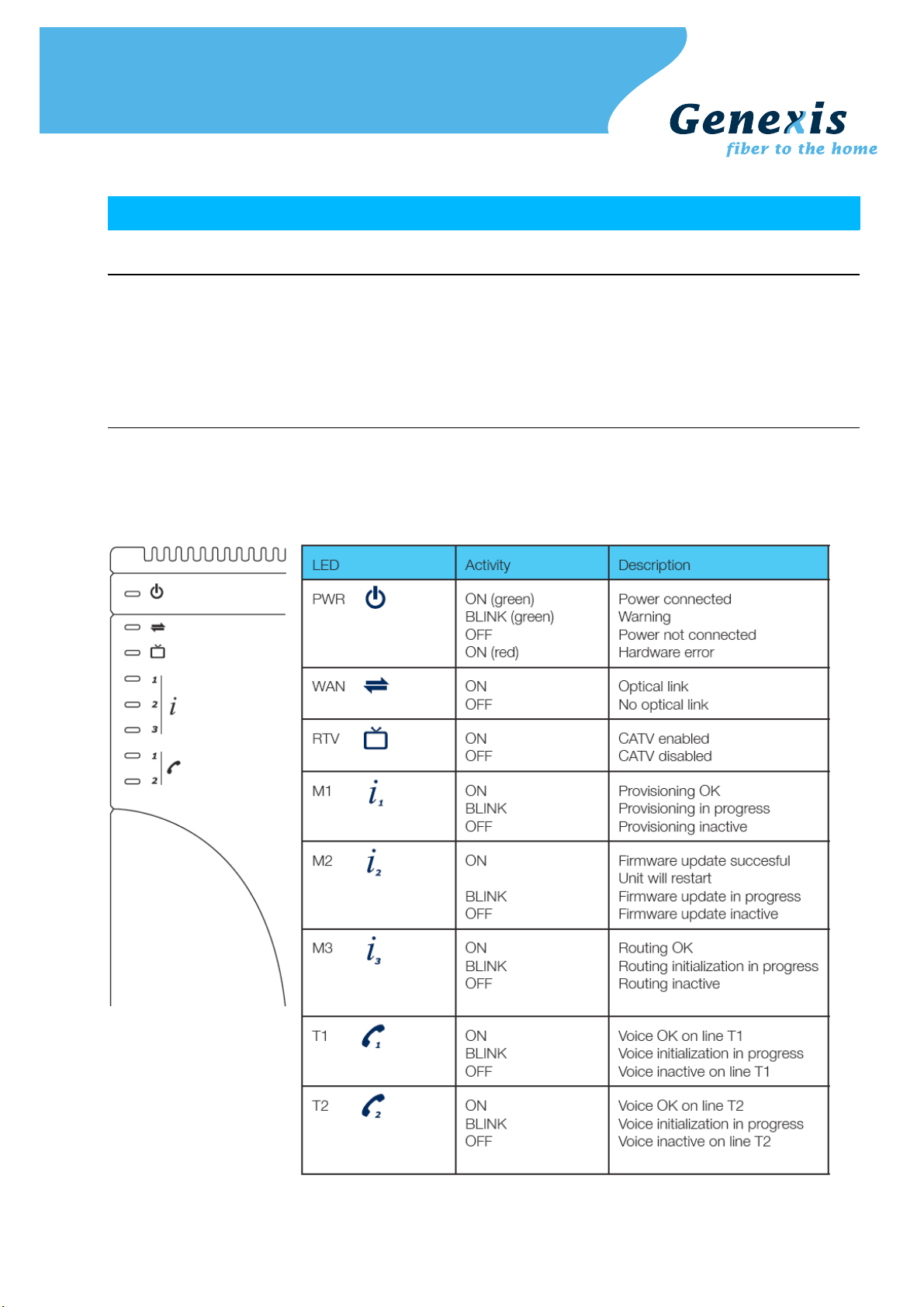
The front of the router
The front of the router is shown below. The status LEDs on the front of the router can be used to get status
information. A short description is given in the table below.
Copyright © Genexis BV. All rights reserved 3
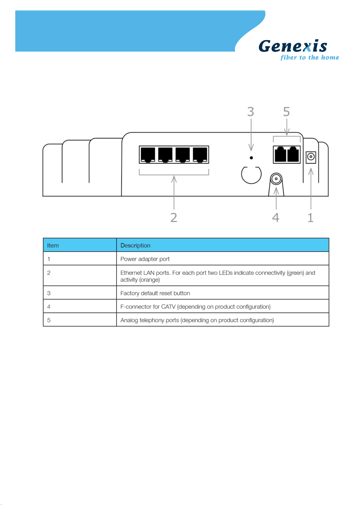
The side of the router
The side of the router is shown below. A short description of the port connections is given in the table below.
The presence of the POTS voice ports, and the F-connector for CATV are depending on the configuration of your
router, and may not be present.
Copyright © Genexis BV. All rights reserved 4
Installation
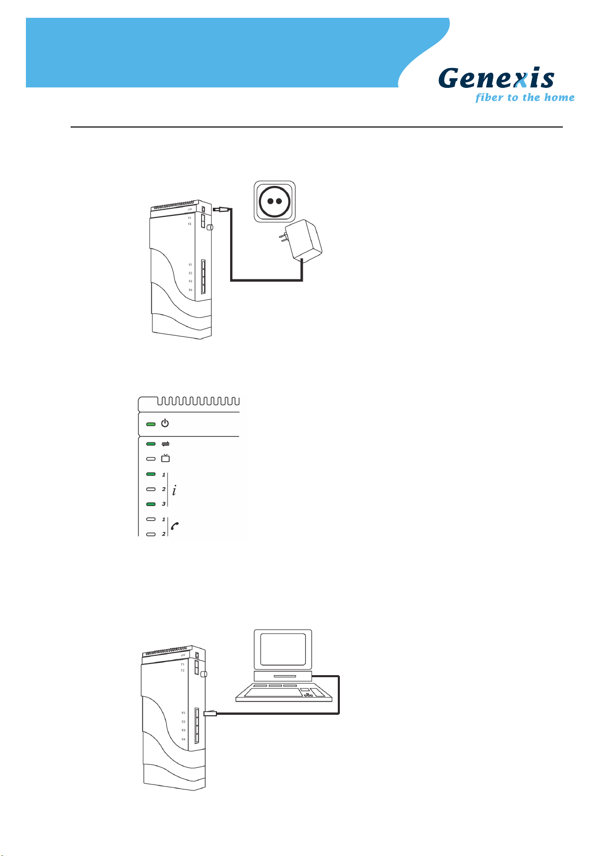
Step 1. Connect the 12V plug of the supplied adapter to the router and connect the adapter to a power socket.
Step 2. The unit will now start up. The start-up sequence takes less than 3 minutes. After the start-up sequence
Step 3. Connect a computer to one of the routed LAN port on the Genexis router, using an Ethernet cable with a
the following LEDs should be on: PWR, WAN, M1, and M3.
If any of above mentioned LEDs is off or blinking for more than 3 minutes after powering on the router,
please refer to the troubleshooting section.
RJ-45 connector. Your provider can tell you which ports routing is enabled.
Copyright © Genexis BV. All rights reserved 5

Step 4. This step is optional, and is only relevant if the router has voice ports
The indicators T1 and T2 indicate if voice is enabled (LED ON) on voice port T1 and/or voice port T2
respectively. A standard analog telephone can be connected to the active ports, using a RJ-11
connector.
Step 5. This step is optional, and is only relevant if the router has a CATV receiver
The indicator RTV indicates if the (radio and) television signal is enabled (LED ON). Your radio or
television can be connected using a coaxial cable with a male F-connector.
Copyright © Genexis BV. All rights reserved 6
Getting started
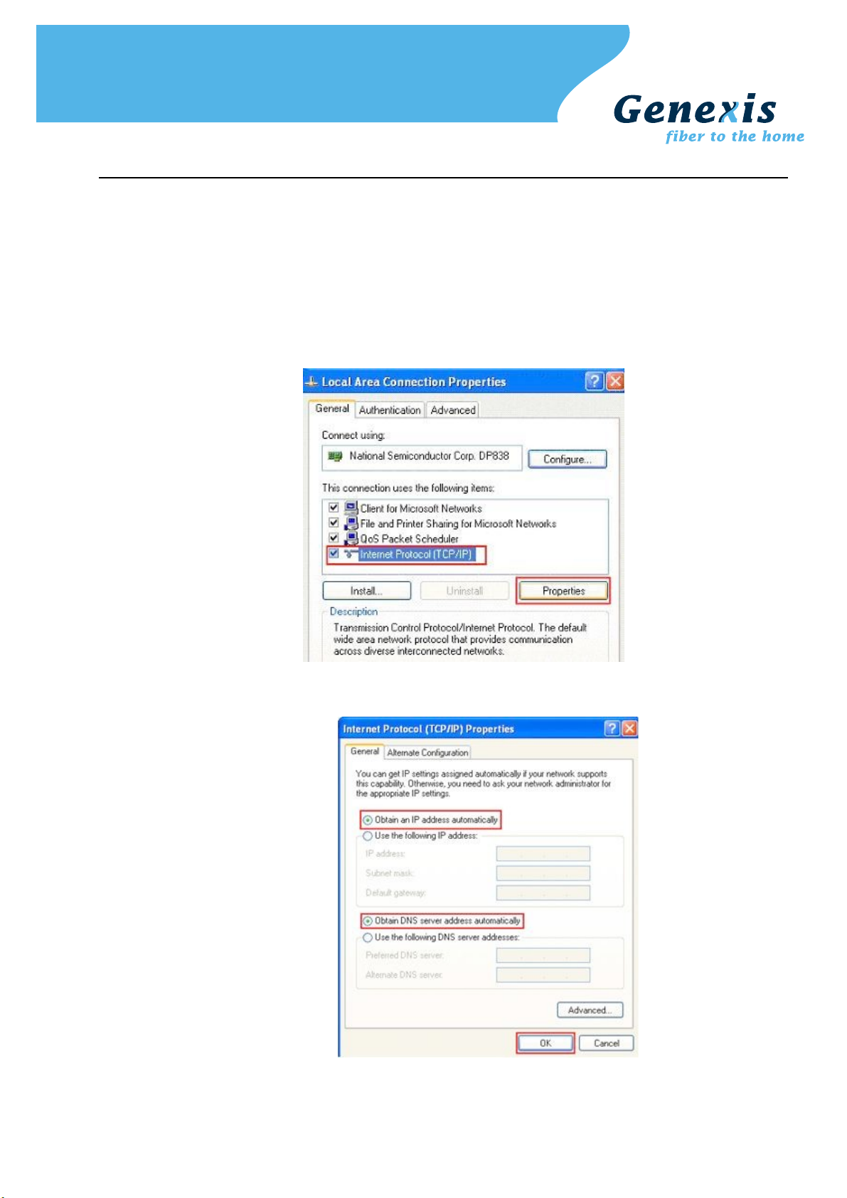
Step 1. Setup your network adapter properly:
Windows XP/Vista
➢ Go to "Start" and click on "Control panel"
➢ The Control Panel window will appear. Double click on "Network Connections"
➢ The Network Connections window will appear. Identify the correct network card, and right click on
correct "Local Area Connection" and click "Properties"
➢ Select "Internet Protocol (TCP/IP)". Click on "Properties"
➢ Make sure "Obtain an IP address automatically", and "Obtain DNS server address automatically" are
selected. Save the settings by clicking "OK"
Copyright © Genexis BV. All rights reserved 7

MacOS X
➢ Go to "Apple-symbol" and click on "System Preferences"
➢ The System Preferences window will appear. Click on "Network"
➢ The Network window will appear. Click on "Ethernet"
➢ Make sure "Using DHCP" is selected. Save the settings by clicking "Apply"
Step 2. Launch the web browser and check if your connection is working. If your connection is not working,
please refer to the troubleshooting section.
Copyright © Genexis BV. All rights reserved 8
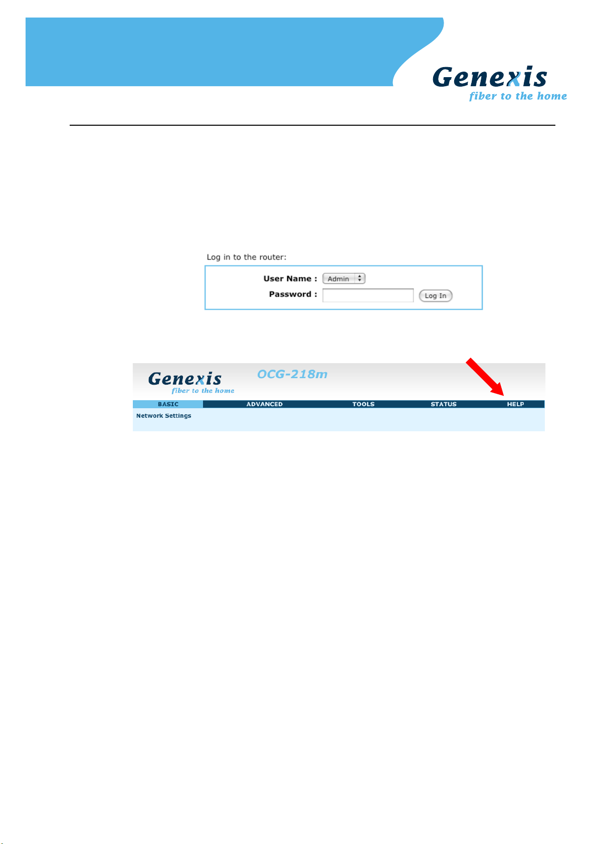
Configuring the router (optional)
Note: changing the configuration is only advised for advanced users and might interrupt your connection. Please refer
to the troubleshooting section on how to reset the router settings back to the factory default settings.
Step 1. Launch the web browser on your computer and enter the router's default IP address '192.168.0.1' in
Step 2. Log in as 'Admin' or 'User' which both default to a blank password. It is recommended to change the
Step 3. Configure the router to the desired configuration. Information about the settings can be found in the
the address field.
password after the first log in.
"Router settings" sections.
Copyright © Genexis BV. All rights reserved 9

Troubleshooting
Copyright © Genexis BV. All rights reserved 10

Appendix: Router settings
Basic
Network Settings
Router Settings
These are the settings of the LAN (Local Area Network) interface for the router. The router's local network (LAN)
settings are configured based on the IP Address and Subnet Mask assigned in this section. The IP address is also
used to access this Web-based management interface. It is recommended that you use the default settings if
you do not have an existing network.
Router IP
Address
Subnet Mask The subnet mask of your router on the local area network.
The IP address of your router on the local area network. Your local area network settings
are based on the address assigned here. For example, 192.168.0.1.
Local Domain
Name
Enable DNS Relay When DNS Relay is enabled, the router plays the role of a DNS server. DNS requests sent
RIP (Routing Information Protocol)
RIP enables the router to share routing information with other routers and hosts on the LAN.
Enable RIP Enable RIP if the LAN has multiple routers or if the LAN has other hosts that listen for RIP
Accept Updates The "Accept Updates" option controls whether the router updates its routing tables when
RIP Operating
mode
This entry is optional. Enter a domain name for the local network. LAN computers will
assume this domain name when they get an address from the router's built in DHCP
server. So, for example, if you enter mynetwork.net here, and you have a LAN side
laptop with a name of chris, that laptop will be known as chris.mynetwork.net. Note,
however, the entered domain name can be overridden by the one obtained from the
router's upstream DHCP server.
to the router are forwarded to the ISP's DNS server. This provides a constant DNS
address that LAN computers can use, even when the router obtains a different DNS
server address from the ISP upon re-establishing the WAN connection. You should disable
DNS relay if you implement a LAN-side DNS server as a virtual server.
messages, such as auto-IP devices or the Windows XP RIP Listener Service.
it receives RIP messages from other LAN devices. Disable "Accept Updates" if not needed
or if RIP messages could originate from an insecure device on the LAN. Enable "Accept
Updates" only if operation of your network requires updates from other routers, and if
you have assured the security of RIP messages on your network.
This router supports both version 2 and version 1 of the RIP specification.
V1. Use if none of the routers supports Version 2.
V2 Broadcast. Use if some routers are capable of Version 2, but some are only capable of
Version 1.
V2 Multicast. Use if this is the only router on the LAN or if all the routers support Version
2.
Router Metric The additional cost of routing a packet through this router. The normal value for a simple
Act as default
router
RIP Password This router supports the use of clear-text passwords in RIP version 2 messages. Only
Copyright © Genexis BV. All rights reserved 11
network is 1. This metric is added to routes learned from other routers; it is not added to
static or system routes.
Make this router the preferred destination for packets that are not otherwise destined.
routers with the same RIP password can share routes via RIP. RIP passwords serve more
as a mechanism to limit route sharing rather than as a security mechanism. You might
use RIP passwords, for example, to prevent routes from one subnet from being seen by a
router on another subnet that has conflicting IP addresses. Enter the password twice for
verification. Leave both password fields empty if RIP passwords are not used.

DHCP Server Settings
DHCP stands for Dynamic Host Configuration Protocol. The DHCP section is where you configure the built-in
DHCP Server to assign IP addresses to the computers and other devices on your local area network (LAN).
Enable DHCP
Server
Once your router is properly configured and this option is enabled, the DHCP Server will
manage the IP addresses and other network configuration information for computers and
other devices connected to your Local Area Network. There is no need for you to do this
yourself.
The computers (and other devices) connected to your LAN also need to have their TCP/IP
configuration set to "DHCP" or "Obtain an IP address automatically".
When you set Enable DHCP Server, the following options are displayed.
DHCP IP Address
Range
DHCP Lease Time The amount of time that a computer may have an IP address before it is required to
These two IP values (from and to) define a range of IP addresses that the DHCP Server
uses when assigning addresses to computers and devices on your Local Area Network.
Any addresses that are outside of this range are not managed by the DHCP Server; these
could, therefore, be used for manually configured devices or devices that cannot use
DHCP to obtain network address details automatically.
It is possible for a computer or device that is manually configured to have an address
that does reside within this range. In this case the address should be reserved (see DHCP
Reservation below), so that the DHCP Server knows that this specific address can only be
used by a specific computer or device.
Your router, by default, has a static IP address of 192.168.0.1. This means that addresses
192.168.0.2 to 192.168.0.254 can be made available for allocation by the DHCP Server.
Example:
Your router uses 192.168.0.1 for the IP address. You've assigned a computer that you
want to designate as a Web server with a static IP address of 192.168.0.3. You've
assigned another computer that you want to designate as an FTP server with a static IP
address of 192.168.0.4. Therefore the starting IP address for your DHCP IP address
range needs to be 192.168.0.5 or greater.
Example:
Suppose you configure the DHCP Server to manage addresses from 192.168.0.100 to
192.168.0.199. This means that 192.168.0.3 to 192.168.0.99 and 192.168.0.200 to
192.168.0.254 are NOT managed by the DHCP Server. Computers or devices that use
addresses from these ranges are to be manually configured. Suppose you have a web
server computer that has a manually configured address of 192.168.0.100. Because this
falls within the "managed range" be sure to create a reservation for this address and
match it to the relevant computer (see Static DHCP Client below).
renew the lease. The lease functions just as a lease on an apartment would. The initial
lease designates the amount of time before the lease expires. If the tenant wishes to
retain the address when the lease is expired then a new lease is established. If the lease
expires and the address is no longer needed than another tenant may use the address.
Always Broadcast If all the computers on the LAN successfully obtain their IP addresses from the router's
NetBIOS
announcement
Learn NetBIOS
from WAN
NetBIOS Scope This is an advanced setting and is normally left blank. This allows the configuration of a
NetBIOS node
type
Copyright © Genexis BV. All rights reserved 12
DHCP server as expected, this option can remain disabled. However, if one of the
computers on the LAN fails to obtain an IP address from the router's DHCP server, it may
have an old DHCP client that incorrectly turns off the broadcast flag of DHCP packets.
Enabling this option will cause the router to always broadcast its responses to all clients,
thereby working around the problem, at the cost of increased broadcast traffic on the
LAN.
Check this box to allow the DHCP Server to offer NetBIOS configuration settings to the
LAN hosts. NetBIOS allows LAN hosts to discover all other computers within the network,
e.g. within Network Neighbourhood.
If NetBIOS advertisement is switched on, switching this setting on causes WINS
information to be learned from the WAN side, if available. Turn this setting off to
configure manually.
NetBIOS 'domain' name under which network hosts operate. This setting has no effect if
the 'Learn NetBIOS information from WAN' is activated
Indicates how network hosts are to perform NetBIOS name registration and discovery.
Broadcast only: Local network broadcast only. This setting is useful where there are no
WINS servers available, however, it is preferred you try Mixed Mode operation first. This
setting has no effect if the 'Learn NetBIOS information from WAN' is activated.

Point-to-Point: Use WINS servers only. This setting is useful to force all NetBIOS
operation to the configured WINS servers. You must have configured at least the primary
WINS server IP to point to a working WINS server.
Mixed Mode: First, the Broadcast operation is performed to register hosts and discover
other hosts, if broadcast operation fails, WINS servers are tried, if any. This mode favours
broadcast operation which may be preferred if WINS servers are reachable by a slow
network link and the majority of network services such as servers and printers are local
to the LAN.
Hybrid: First WINS servers are tried, if any, followed by local network broadcast. This is
generally the preferred mode if you have configured WINS servers.
Primary WINS
Server IP address
Secondary WINS
Server IP address
Add/Edit DHCP Reservation
This option lets you reserve IP addresses, and assign the same IP address to the network device with the
specified MAC address any time it requests an IP address. This is almost the same as when a device has a static
IP address except that the device must still request an IP address from the router. The router will provide the
device the same IP address every time. DHCP Reservations are helpful for server computers on the local
network that are hosting applications such as Web and FTP. Servers on your network should either use a static
IP address or use this option.
Enable Specifies whether the entry will be active or inactive.
Computer Name You can assign a name for each computer that is given a reserved IP address. This may
IP Address The LAN address that you want to reserve.
MAC Address To input the MAC address of your system, enter it in manually or connect to the router's
Configure the IP address of the preferred WINS server. WINS Servers store information
regarding network hosts, allowing hosts to 'register' themselves as well as discover other
available hosts, e.g. for use in Network Neighbourhood. This setting has no effect if the
'Learn NetBIOS information from WAN' is activated.
Configure the IP address of the backup WINS server, if any. This setting has no effect if
the 'Learn NetBIOS information from WAN' is activated.
help you keep track of which computers are assigned this way. Example: Game Server.
Web-Management interface from the system and click the Copy Your PC's MAC Address
button.
A MAC address is usually located on a sticker on the bottom of a network device. The
MAC address is comprised of twelve digits. Each pair of hexadecimal digits are usually
separated by dashes or colons such as 00-0D-88-11-22-33 or 00:0D:88:11:22:33. If
your network device is a computer and the network card is already located inside the
computer, you can connect to the router from the computer and click the Copy Your PC's
MAC Address button to enter the MAC address.
As an alternative, you can locate a MAC address in a specific operating system by
following the steps below:
Go to the Start menu, select Run, type in winipcfg, and hit Enter. A
Windows 98
Windows Me
Windows 2000
Windows XP
Mac OS X
popup window will be displayed. Select the appropriate adapter from the
pull-down menu and you will see the Adapter Address. This is the MAC
address of the device.
Go to your Start menu, select Programs, select Accessories, and select
Command Prompt. At the command prompt type ipconfig /all and hit
Enter. The physical address displayed for the adapter connecting to the
router is the MAC address.
Go to the Apple Menu, select System Preferences, select Network, and
select the Ethernet Adapter connecting to the router. Select the Ethernet
button and the Ethernet ID will be listed. This is the same as the MAC
address.
Save/Update Record the changes you have made into the following list.
Clear Re-initialize this area of the screen, discarding any changes you have made.
DHCP Reservations List
This shows clients that you have specified to have reserved DHCP addresses. Click the Enable checkbox at the
left to directly activate or de-activate the entry. An entry can be changed by clicking the Edit icon or can be
deleted by clicking the Delete icon. When you click the Edit icon, the item is highlighted, and the "Edit DHCP
Copyright © Genexis BV. All rights reserved 13

Reservation" section is activated for editing.
Number of Dynamic DHCP Clients
In this section you can see what LAN devices are currently leasing IP addresses.
Revoke The Revoke option is available for the situation in which the lease table becomes full or
nearly full, you need to recover space in the table for new entries, and you know that
some of the currently allocated leases are no longer needed. Clicking Revoke cancels the
lease for a specific LAN device and frees an entry in the lease table. Do this only if the
device no longer needs the leased IP address, because, for example, it has been removed
from the network.
Reserve The Reserve option converts this dynamic IP allocation into a DHCP Reservation and adds
the corresponding entry to the DHCP Reservations List.
Advanced
Virtual Server
The Virtual Server option gives Internet users access to services on your LAN. This feature is useful for hosting
online services such as FTP, Web, or game servers. For each Virtual Server, you define a public port on your
router for redirection to an internal LAN IP Address and LAN port.
Example:
You are hosting a Web Server on a PC that has LAN IP Address of 192.168.0.50 and your ISP is blocking Port 80.
1. Name the Virtual Server (for example: Web Server)
2. Enter the IP Address of the machine on your LAN (for example: 192.168.0.50
3. Enter the Private Port as [80]
4. Enter the Public Port as [8888]
5. Select the Protocol (for example TCP).
6. Ensure the schedule is set to Always
7. Click Save to add the settings to the Virtual Servers List
8. Repeat these steps for each Virtual Server Rule you wish to add.
With this Virtual Server entry, all Internet traffic on Port 8888 will be redirected to your internal web server on
port 80 at IP Address 192.168.0.50.
Add/Edit Virtual Server
Enable Specifies whether the entry will be active or inactive.
Name Assign a meaningful name to the virtual server, for example Web Server. Several well-
known types of virtual server are available from the "Application Name" drop-down list.
Selecting one of these entries fills some of the remaining parameters with standard
values for that type of server.
IP Address The IP address of the system on your internal network that will provide the virtual
Protocol Select the protocol used by the service. The common choices -- UDP, TCP, and both UDP
Public Port The port that will be accessed from the Internet.
Private Port The port that will be used on your internal network.
Schedule Select a schedule for when the service will be enabled. If you do not see the schedule
Inbound Filter Select a filter that controls access as needed for this virtual server. If you do not see the
service, for example 192.168.0.50. You can select a computer from the list of DHCP
clients in the "Computer Name" drop-down menu, or you can manually enter the IP
address of the server computer.
and TCP -- can be selected from the drop-down menu. To specify any other protocol,
select "Other" from the list, then enter the corresponding protocol number (as assigned
by the IANA) in the Protocol box.
you need in the list of schedules, go to the Tools Schedules→ screen and create a new
schedule.
filter you need in the list of filters, go to the Advanced Inbound Filter screen and create→
a new filter.
Copyright © Genexis BV. All rights reserved 14

Save/Update Record the changes you have made into the following list.
Clear Re-initialize this area of the screen, discarding any changes you have made.
Virtual Server List
This is a list of the defined Virtual Servers. Click the Enable checkbox at the left to directly activate or deactivate the entry. An entry can be changed by clicking the Edit icon or can be deleted by clicking the Delete
icon. When you click the Edit icon, the item is highlighted, and the "Edit Virtual Servers" section is activated for
editing.
Note: You might have trouble accessing a virtual server using its public identity (WAN-side IP-address of the
gateway or its dynamic DNS name) from a machine on the LAN. Your requests may not be looped back or you
may be redirected to the "Forbidden" page.
This will happen if you have an Access Control Rule configured for this LAN machine.
The requests from the LAN machine will not be looped back if Internet access is blocked at the time of access.
To work around this problem, access the LAN machine using its LAN-side identity.
Requests may be redirected to the "Forbidden" page if web access for the LAN machine is restricted by an
Access Control Rule. Add the WAN-side identity (WAN-side IP-address of the router or its dynamic DNS name)
on the Advanced Web→ Filter screen to work around this problem.
Special Applications
An application rule is used to open single or multiple ports on your router when the router senses data sent to
the Internet on a "trigger" port or port range. An application rule applies to all computers on your internal
network.
Add/Edit Application Rule
Example:
You need to configure your router to allow a software application running on any computer on your network to
connect to a web-based server or another user on the Internet.
Enable Specifies whether the entry will be active or inactive.
Name Enter a name for the Special Application Rule, for example Game App, which will help you
identify the rule in the future. Alternatively, you can select from the Application Name list
of common applications.
Application Name Instead of entering a name for the Special Application rule, you can select from this list
Trigger Ports Enter the outgoing port range used by your application (for example 6500-6700).
Trigger Traffic
Type
Firewall Ports Enter the port range that you want to open up to Internet traffic (for example 6000-
Firewall Traffic
Type
Schedule Select a schedule for when this rule is in effect. If you do not see the schedule you need
Save/Update Record the changes you have made into the following list.
Clear Re-initialize this area of the screen, discarding any changes you have made.
With the above example application rule enabled, the router will open up a range of ports from 6000-6200 for
incoming traffic from the Internet, whenever any computer on the internal network opens up an application that
sends data to the Internet using a port in the range of 6500-6700.
of common applications, and the remaining configuration values will be filled in
accordingly.
Select the outbound protocol used by your application (for example Both).
6200).
Select the protocol used by the Internet traffic coming back into the router through the
opened port range (for example Both).
in the list of schedules, go to the Tools Schedules screen and create a new schedule. →
Application Rules
This is a list of the defined application rules. Click the Enable checkbox at the left to directly activate or deactivate the entry. An entry can be changed by clicking the Edit icon or can be deleted by clicking the Delete
icon. When you click the Edit icon, the item is highlighted, and the "Edit Application Rule" section is activated for
editing.
Copyright © Genexis BV. All rights reserved 15

Port Forwarding
Multiple connections are required by some applications, such as internet games, video conferencing, Internet
telephony, and others. These applications have difficulties working through NAT (Network Address Translation).
This section is used to open multiple ports or a range of ports in your router and redirect data through those
ports to a single PC on your network. You can enter ports in various formats:
Range (50-100)
Individual (80, 68, 888)
Mixed (1020-5000, 689)
Example:
Suppose you are hosting an online game server that is running on a PC with a private IP Address of
192.168.0.50. This game requires that you open multiple ports (6159-6180, 99) on the router so Internet users
can connect.
Add/Edit Port Forwarding Rule
Use this section to add a Port Forwarding Rule to the following list or to edit a rule already in the list.
Enable Specifies whether the entry will be active or inactive.
Name Give the rule a name that is meaningful to you, for example Game Server. You can also
select from a list of popular games, and many of the remaining configuration values will
be filled in accordingly. However, you should check whether the port values have changed
since this list was created, and you must fill in the IP address field.
IP Address Enter the local network IP address of the system hosting the server, for example
TCP Ports Enter the TCP ports to open (for example 6159-6180, 99).
UDP Ports Enter the UDP ports to open (for example 6159-6180, 99).
Schedule Select a schedule for the times when this rule is in effect. If you do not see the schedule
Inbound Filter Select a filter that controls access as needed for this rule. If you do not see the filter you
Save/Update Record the changes you have made into the following list.
Clear Re-initialize this area of the screen, discarding any changes you have made.
With the above example values filled in and this Port Forwarding Rule enabled, all TCP and UDP traffic on ports
6159 through 6180 and port 99 is passed through the router and redirected to the Internal Private IP Address of
your Game Server at 192.168.0.50.
Note that different LAN computers cannot be associated with Port Forwarding rules that contain any ports in
common; such rules would contradict each other.
Port Forwarding Rules
This is a list of the defined Port Forwarding Rules. Click the Enable checkbox at the left to directly activate or deactivate the entry. An entry can be changed by clicking the Edit icon or can be deleted by clicking the Delete
icon. When you click the Edit icon, the item is highlighted, and the "Edit Port Forwarding Rule" section is
activated for editing.
192.168.0.50. You can select a computer from the list of DHCP clients in the "Computer
Name" drop-down menu, or you can manually enter the IP address of the server
computer.
you need in the list of schedules, go to the Tools Schedules screen and create a new→
schedule.
need in the list of filters, go to the Advanced Inbound Filter screen and create a new→
filter.
Routing
Add/Edit Route
Adds a new route to the IP routing table or edits an existing route.
Enable Specifies whether the entry will be enabled or disabled.
Route is via
another gateway
Copyright © Genexis BV. All rights reserved 16
When checked, the Gateway box is displayed and must be completed with the IP address
of the gateway/router to which this route corresponds. Datagrams sent to this route are
forwarded onto the given Gateway IP address for further processing. When unchecked,
this route represents a local route for which this router has its own IP address with which
to communicate.

Name Assign a meaningful name to this route for your own use.
Netmask One bits in the mask specify which bits of the IP address must match.
Metric The route metric is a value from 1 to 16 that indicates the cost of using this route. A
Interface Specifies the interface -- LAN or WAN -- that the IP packet must use to transit out of the
Save/Update Record the changes you have made into the following list.
Clear Re-initialize this area of the screen, discarding any changes you have made.
Routes via another gateway
Destination IP The IP address of packets that will take this route.
Gateway Specifies the next hop to be taken if this route is used.
Routes not via another gateway
Router's IP Routes not via another gateway are routes to PC connected directly to one of the router's
Routes List
The section shows the current routing table entries. Certain required routes are predefined and cannot be
changed. Routes that you add can be changed by clicking the Edit icon or can be deleted by clicking the Delete
icon. When you click the Edit icon, the item is highlighted, and the "Edit Route" section is activated for editing.
Click the Enable checkbox at the left to directly activate or de-activate the entry.
value of 1 is the lowest cost, and 15 is the highest cost. A value of 16 indicates that the
route is not reachable from this router. When trying to reach a particular destination,
computers on your network will select the best route, ignoring unreachable routes.
router, when this route is used.
own interfaces. The IP address this router uses when talking to devices on this route is
specified here.
Access Control
The Access Control section allows you to control access in and out of devices on your network. Use this feature
as Parental Controls to only grant access to approved sites, limit web access based on time or dates, and/or
block access from applications such as peer-to-peer utilities or games.
Enable By default, the Access Control feature is disabled. If you need Access Control, check this
Add Policy Click this button to start creating a new access control policy.
Policy Wizard The Policy Wizard guides you through the steps of defining each access control policy. A
Policy Table
This section shows the currently defined access control policies. A policy can be changed by clicking the Edit
icon, or deleted by clicking the Delete icon. When you click the Edit icon, the Policy Wizard starts and guides you
through the process of changing a policy. You can enable or disable specific policies in the list by clicking the
"Enable" checkbox.
option.
Note: When Access Control is disabled, every device on the LAN has unrestricted access
to the Internet. However, if you enable Access Control, Internet access is restricted for
those devices that have an Access Control Policy configured for them. All other devices
have unrestricted access to the Internet.
policy is the "Who, What, When, and How" of access control -- whose computer will be
affected by the control, what internet addresses are controlled, when will the control be
in effect, and how is the control implemented. You can define multiple policies. The Policy
Wizard starts when you click the button below and also when you edit an existing policy.
Website Filter
The Web sites listed here are used when the Web Filter option is enabled in Advanced Access Control. →
Add Web Filtering Rule
This section is where you add the Web sites to be used for Access Control.
Website
URL/Domain
Copyright © Genexis BV. All rights reserved 17
Enter the URL (address) of the Web Site that you want to allow; for example:

google.com. Do not enter the http:// preceding the URL. Enter the most inclusive
domain; for example, enter example.com and access will be permitted to both
www.example.com and support.example.com.
Save Record the changes you have made into the following list.
Note: Many web sites construct pages with images and content from other web sites. Access will be forbidden if
you do not enable all the web sites used to construct a page. For example, to access my.yahoo.com, you need to
enable access to yahoo.com, yimg.com, and doubleclick.net.
Website Filtering Rules
The section lists the currently allowed web sites.
Firewall Settings
The router provides a tight firewall by virtue of the way NAT works. Unless you configure the router to the
contrary, the NAT does not respond to unsolicited incoming requests on any port, thereby making your LAN
invisible to Internet cyberattackers. However, some network applications cannot run with a tight firewall. Those
applications need to selectively open ports in the firewall to function correctly. The options on this page control
several ways of opening the firewall to address the needs of specific types of applications. See also
Advanced Virtual Server, Advanced Port Forwarding, Advanced Application Rules, and Advanced Network→ → → →
(UPnP) for related options.
Firewall Settings
Enable SPI SPI ("stateful packet inspection" also known as "dynamic packet filtering") helps to
prevent cyberattacks by tracking more state per session. It validates that the traffic
passing through that session conforms to the protocol. When the protocol is TCP, SPI
checks that packet sequence numbers are within the valid range for the session,
discarding those packets that do not have valid sequence numbers.
Whether SPI is enabled or not, the router always tracks TCP connection states and
ensures that each TCP packet's flags are valid for the current state.
NAT Endpoint Filtering
The NAT Endpoint Filtering options control how the router's NAT manages incoming connection requests to ports
that are already being used.
Endpoint
Independent
Address
Restricted
Port And Address
Restricted
Note that some of these options can interact with other port restrictions. Endpoint Independent Filtering takes
priority over inbound filters or schedules, so it is possible for an incoming session request related to an outgoing
session to enter through a port in spite of an active inbound filter on that port. However, packets will be rejected
as expected when sent to blocked ports (whether blocked by schedule or by inbound filter) for which there are
no active sessions. Port and Address Restricted Filtering ensures that inbound filters and schedules work
precisely, but prevents some level of connectivity, and therefore might require the use of port triggers, virtual
servers, or port forwarding to open the ports needed by the application. Address Restricted Filtering gives a
compromise position, which avoids problems when communicating with certain other types of NAT router
(symmetric NATs in particular) but leaves inbound filters and scheduled access working as expected.
UDP Endpoint
Filtering
Once a LAN-side application has created a connection through a specific port, the NAT will
forward any incoming connection requests with the same port to the LAN-side application
regardless of their origin. This is the least restrictive option, giving the best connectivity
and allowing some applications (P2P applications in particular) to behave almost as if
they are directly connected to the Internet.
The NAT forwards incoming connection requests to a LAN-side host only when they come
from the same IP address with which a connection was established. This allows the
remote application to send data back through a port different from the one used when
the outgoing session was created.
The NAT does not forward any incoming connection requests with the same port address
as an already establish connection.
Controls endpoint filtering for packets of the UDP protocol.
TCP Endpoint
Filtering
Formerly, the terms "Full Cone", "Restricted Cone", "Port Restricted Cone" and "Symmetric" were used to refer
Copyright © Genexis BV. All rights reserved 18
Controls endpoint filtering for packets of the TCP protocol.

to different variations of NATs. These terms are purposely not used here, because they do not fully describe the
behavior of this router's NAT. While not a perfect mapping, the following loose correspondences between the
"cone" classification and the "endpoint filtering" modes can be drawn: if this router is configured for endpoint
independent filtering, it implements full cone behavior; address restricted filtering implements restricted cone
behavior; and port and address restricted filtering implements port restricted cone behavior.
NAT Port Preservation
NAT Port preservation (on by default) tries to ensure that, when a LAN host makes an Internet connection, the
same LAN port is also used as the Internet visible port. This ensures best compatibility for internet
communications.
Under some circumstances it may be desirable to turn off this feature.
Anti-Spoof checking
Enabling this option can provide protection from certain kinds of "spoofing" attacks. However, enable this option
with care. With some modems, the WAN connection may be lost when this option is enabled. In that case, it
may be necessary to change the LAN subnet to something other than 192.168.0.x (192.168.2.x, for example),
to re-establish the WAN connection.
DMZ Host
DMZ means "Demilitarized Zone." If an application has trouble working from behind the router, you can expose
one computer to the Internet and run the application on that computer.
When a LAN host is configured as a DMZ host, it becomes the destination for all incoming packets that do not
match some other incoming session or rule. If any other ingress rule is in place, that will be used instead of
sending packets to the DMZ host; so, an active session, virtual server, active port trigger, or port forwarding rule
will take priority over sending a packet to the DMZ host. (The DMZ policy resembles a default port forwarding
rule that forwards every port that is not specifically sent anywhere else.)
The router provides only limited firewall protection for the DMZ host. The router does not forward a TCP packet
that does not match an active DMZ session, unless it is a connection establishment packet (SYN). Except for this
limited protection, the DMZ host is effectively "outside the firewall". Anyone considering using a DMZ host
should also consider running a firewall on that DMZ host system to provide additional protection.
Packets received by the DMZ host have their IP addresses translated from the WAN-side IP address of the router
to the LAN-side IP address of the DMZ host. However, port numbers are not translated; so applications on the
DMZ host can depend on specific port numbers.
The DMZ capability is just one of several means for allowing incoming requests that might appear unsolicited to
the NAT. In general, the DMZ host should be used only if there are no other alternatives, because it is much
more exposed to cyberattacks than any other system on the LAN. Thought should be given to using other
configurations instead: a virtual server, a port forwarding rule, or a port trigger. Virtual servers open one port for
incoming sessions bound for a specific application (and also allow port redirection and the use of ALGs). Port
forwarding is rather like a selective DMZ, where incoming traffic targeted at one or more ports is forwarded to a
specific LAN host (thereby not exposing as many ports as a DMZ host). Port triggering is a special form of port
forwarding, which is activated by outgoing traffic, and for which ports are only forwarded while the trigger is
active.
Few applications truly require the use of the DMZ host. Following are examples of when a DMZ host might be
required:
• A host needs to support several applications that might use overlapping ingress ports such that two
port forwarding rules cannot be used because they would potentially be in conflict.
• To handle incoming connections that use a protocol other than ICMP, TCP, UDP, and IGMP (also GRE and
ESP, when these protocols are enabled by the PPTP and IPSec ALGs ).
Enable DMZ Note: Putting a computer in the DMZ may expose that computer to a variety of security
risks. Use of this option is only recommended as a last resort.
DMZ IP Address Specify the LAN IP address of the LAN computer that you want to have unrestricted
Non-UDP/TCP/ICMP LAN Sessions
When a LAN application that uses a protocol other than UDP, TCP, or ICMP initiates a session to the Internet, the
router's NAT can track such a session, even though it does not recognize the protocol. This feature is useful
because it enables certain applications (most importantly a single VPN connection to a remote host) without the
need for an ALG.
Note that this feature does not apply to the DMZ host (if one is enabled). The DMZ host always handles these
kinds of sessions.
Enable Enabling this option (the default setting) enables single VPN connections to a remote
Copyright © Genexis BV. All rights reserved 19
Internet communication. If this computer obtains its address Automatically using DHCP,
then you may want to make a static reservation on the Basic Network Settings page so→
that the IP address of the DMZ computer does not change.
host. (But, for multiple VPN connections, the appropriate VPN ALG must be used.)

Disabling this option, however, only disables VPN if the appropriate VPN ALG is also
disabled.
Application Level Gateway (ALG) Configuration
Here you can enable or disable ALGs. Some protocols and applications require special handling of the IP payload
to make them work with network address translation (NAT). Each ALG provides special handling for a specific
protocol or application. A number of ALGs for common applications are enabled by default.
PPTP Allows multiple machines on the LAN to connect to their corporate networks using PPTP
protocol. When the PPTP ALG is enabled, LAN computers can establish PPTP VPN
connections either with the same or with different VPN servers. When the PPTP ALG is
disabled, the router allows VPN operation in a restricted way -- LAN computers are
typically able to establish VPN tunnels to different VPN Internet servers but not to the
same server. The advantage of disabling the PPTP ALG is to increase VPN performance.
Enabling the PPTP ALG also allows incoming VPN connections to a LAN side VPN server
(refer to Advanced Virtual Server). →
IPSec (VPN) Allows multiple VPN clients to connect to their corporate networks using IPSec. Some VPN
RTSP Allows applications that use Real Time Streaming Protocol to receive streaming media
Windows/MSN
Messenger
FTP Allows FTP clients and servers to transfer data across NAT. Refer to the Advanced Virtual→
H.323
(Netmeeting)
SIP Allows devices and applications using VoIP (Voice over IP) to communicate across NAT.
Wake-On-LAN This feature enables forwarding of "magic packets" (that is, specially formatted wake-up
clients support traversal of IPSec through NAT. This option may interfere with the
operation of such VPN clients. If you are having trouble connecting with your corporate
network, try disabling this option.
Check with the system administrator of your corporate network whether your VPN client
supports NAT traversal.
Note that L2TP VPN connections typically use IPSec to secure the connection. To achieve
multiple VPN pass-through in this case, the IPSec ALG must be enabled.
from the internet. QuickTime and Real Player are some of the common applications using
this protocol.
Supports use on LAN computers of Microsoft Windows Messenger (the Internet
messaging client that ships with Microsoft Windows) and MSN Messenger. The SIP ALG
must also be enabled when the Windows Messenger ALG is enabled.
Server page if you want to host an FTP server.
Allows H.323 (specifically Microsoft Netmeeting) clients to communicate across NAT. Note
that if you want your buddies to call you, you should also set up a virtual server for
NetMeeting. Refer to the Advanced Virtual Server page for information on how to set up→
a virtual server.
Some VoIP applications and devices have the ability to discover NAT devices and work
around them. This ALG may interfere with the operation of such devices. If you are
having trouble making VoIP calls, try turning this ALG off.
packets) from the WAN to a LAN computer or other device that is "Wake on LAN" (WOL)
capable. The WOL device must be defined as such on the Advanced Virtual Server page.→
The LAN IP address for the virtual server is typically set to the broadcast address
192.168.0.255. The computer on the LAN whose MAC address is contained in the magic
packet will be awakened.
MMS Allows Windows Media Player, using MMS protocol, to receive streaming media from the
internet.
Inbound Filter
When you use the Virtual Server, Port Forwarding, or Remote Administration features to open specific ports to
traffic from the Internet, you could be increasing the exposure of your LAN to cyberattacks from the Internet. In
these cases, you can use Inbound Filters to limit that exposure by specifying the IP addresses of internet hosts
that you trust to access your LAN through the ports that you have opened. You might, for example, only allow
access to a game server on your home LAN from the computers of friends whom you have invited to play the
games on that server.
Inbound Filters can be used for limiting access to a server on your network to a system or group of systems.
Filter rules can be used with Virtual Server, Gaming, or Remote Administration features. Each filter can be used
for several functions; for example a "Game Clan" filter might allow all of the members of a particular gaming
group to play several different games for which gaming entries have been created. At the same time an "Admin"
filter might only allows systems from your office network to access the WAN admin pages and an FTP server you
Copyright © Genexis BV. All rights reserved 20

use at home. If you add an IP address to a filter, the change is effected in all of the places where the filter is
used.
Add/Edit Inbound Filter Rule
Here you can add entries to the Inbound Filter Rules List below, or edit existing entries.
Name Enter a name for the rule that is meaningful to you.
Action The rule can either Allow or Deny messages.
Remote IP Range Define the ranges of Internet addresses this rule applies to. For a single IP address, enter
Save/Update Record the changes you have made into the following list.
Clear Re-initialize this area of the screen, discarding any changes you have made.
Inbound Filter Rules List
The section lists the current Inbound Filter Rules. An entry can be changed by clicking the Edit icon or can be
deleted by clicking the Delete icon. When you click the Edit icon, the item is highlighted, and the "Edit Inbound
Filter Rule" section is activated for editing.
In addition to the filters listed here, two predefined filters are available wherever inbound filters can be applied:
Allow All Permit any WAN user to access the related capability.
Deny All Prevent all WAN users from accessing the related capability. (LAN users are not affected
the same address in both the Start and End boxes. Up to eight ranges can be entered.
The Enable checkbox allows you to turn on or off specific entries in the list of ranges.
by Inbound Filter Rules.)
Advanced Network
UPnP
UPnP is short for Universal Plug and Play, which is a networking architecture that provides compatibility among
networking equipment, software, and peripherals. This router has optional UPnP capability, and can work with
other UPnP devices and software.
Enable UPnP If you need to use the UPnP functionality, you can enable it here.
Allow Users to
disable Internet
Access
Disabling this option prevents UPnP clients from terminating the WAN connection.
Allow Users to
modify Virtual
Server Mappings
PPPoE Pass Through
This option controls whether LAN computers can act as PPPoE clients and negotiate PPP sessions through the
router over the WAN ethernet link.
Enable PPPoE
Pass Through
LAN Auto IP
Enables the router to automatically generate its LAN-side IP address and communicate with other LAN
computers that also implement auto-IP, even when the router's DHCP server function is disabled.
Enable LAN Auto
IP
Disabling this option prevents UPnP clients from adding, modifying, deleting, or disabling
virtual server entries.
Enabling this option allows LAN computers to act as PPPoE clients. Disabling this option
prevents LAN computers from establishing PPPoE pass-through connections.
This option should normally remain enabled.
Copyright © Genexis BV. All rights reserved 21

Tools
Administrator Settings
The Administrator Settings section is used to set-up secure access to the Web-based management. By default
no password is configured. It is highly recommended that you create a password to keep your new router
secure.
Admin Password
Enter a password for the user "admin", who will have full access to the Web-based management interface.
User Password
Enter a password for the user "user", who will have read-only access to the Web-based management interface.
Gateway Name
The name of the router can be changed here.
Administration
Inactivity Time
Out
If the router does not detect any administrative activity (from WAN or LAN) during this
number of minutes, it logs the administrator off.
Enable Remote
Management
Remote Admin
Port
Remote Admin
Inbound Filter
Enabling Remote Management allows you to manage the router from anywhere on the
Internet. Disabling Remote Management allows you to manage the router only from
computers on your LAN.
The port that you will use to address the management interface from the Internet. For
example, if you specify port 1080 here, then, to access the router from the Internet, you
would use a URL of the form: http://my.domain.com:1080/.
Select a filter that controls access as needed for this admin port. If you do not see the
filter you need in the list of filters, go to the Advanced Inbound Filter screen and create→
a new filter.
Time
The Time Configuration option allows you to configure, update, and maintain the correct time on the router's
internal system clock. From this section you can set the time zone that you are in and set the Time Server.
Daylight saving can also be configured to automatically adjust the time when needed.
Time Configuration
Current Router
Time
Time Zone Select your local time zone from pull down menu.
Enable Daylight
Saving
Daylight Saving
Offset
DST Start and
DST End
Displays the time currently maintained by the router. If this is not correct, use the
following options to configure the time correctly.
Check this option if your location observes daylight saving time.
Select the time offset, if your location observes daylight saving time.
Select the starting and ending times for the change to and from daylight saving time. For
example, suppose for DST Start you select Month="Oct", Week="3rd", Day="Sun" and
Time="2am". This is the same as saying: "Daylight saving starts on the third Sunday of
October at 2:00 AM."
Automatic Time Configuration
Enable NTP
Server
NTP Server Used Select a Network Time Server for synchronization. You can type in the address of a time
Copyright © Genexis BV. All rights reserved 22
Select this option if you want to synchronize the router's clock to a Network Time Server
over the Internet. If you are using schedules or logs, this is the best way to ensure that
the schedules and logs are kept accurate.
Note that, even when NTP Server is enabled, you must still choose a time zone and set
the daylight saving parameters.
server or select one from the list. If you have trouble using one server, select another.

Set the Date and Time Manually
If you do not have the NTP Server option in effect, you can either manually set the time for your router here, or
you can click the Copy Your Computer's Time Settings button to copy the time from the computer you are using.
(Make sure that computer's time is set correctly.)
Note: If the router loses power for any reason, it cannot keep its clock running, and will not have the correct
time when it is started again. To maintain correct time for schedules and logs, either you must enter the correct
time after you restart the router, or you must enable the NTP Server option.
System
This section allows you to manage the router's configuration settings, reboot the router, and restore the router
to the factory default settings. Restoring the unit to the factory default settings will erase all settings, including
any rules that you've created.
Save To Local
Hard Drive
This option allows you to save the router's configuration to a file on your computer. Be
sure to save the configuration before performing a firmware upgrade.
Load From Local
Hard Drive
Restore To
Factory Default
Reboot The
Device
Use this option to restore previously saved router configuration settings.
This option restores all configuration settings back to the settings that were in effect at
the time the router was shipped from the factory. Any settings that have not been saved
will be lost. If you want to save your router configuration settings, use the Save Settings
option above.
This restarts the router. Useful for restarting when you are not near the device.
Dynamic DNS
The Dynamic DNS feature allows you to host a server (Web, FTP, Game Server, etc.) using a domain name that
you have purchased (www.whateveryournameis.com) with your dynamically assigned IP address. Most
broadband Internet Service Providers assign dynamic (changing) IP addresses. When you use a Dynamic DNS
service provider, your friends can enter your host name to connect to your server, no matter what your IP
address is.
Enable Dynamic
DNS
Server Address Select a dynamic DNS service provider from the pull-down list.
Host Name Enter your host name, fully qualified; for example: myhost.mydomain.net.
Username or Key Enter the username or key provided by your service provider. If the Dynamic DNS
Password or Key Enter the password or key provided by your service provider. If the Dynamic DNS
Enable this option only if you have purchased your own domain name and registered with
a dynamic DNS service provider. The following parameters are displayed when the option
is enabled.
provider supplies only a key, enter that key in all three fields.
provider supplies only a key, enter that key in all three fields.
Verify Password
or Key
Timeout The time between periodic updates to the Dynamic DNS, if your dynamic IP address has
Note: If a dynamic DNS update fails for any reason (for example, when incorrect parameters are entered), the
router automatically disables the Dynamic DNS feature and records the failure in the log.
Note: After configuring the router for dynamic DNS, you can open a browser and navigate to the URL for your
domain (for example http://www.mydomain.info) and the router will attempt to forward the request to port 80
on your LAN. If, however, you do this from a LAN-side computer and there is no virtual server defined for port
80, the router will return the router's configuration home page. Refer to the Advanced Virtual Server→
configuration page to set up a a virtual server.
Re-type the password or key provided by your service provider. If the Dynamic DNS
provider supplies only a key, enter that key in all three fields.
not changed. The timeout period is entered in hours.
System Check
Ping Test
"Ping" is an Internet utility function that sends a series of short messages to a target computer and reports the
results. You can use it to test whether a computer is running, and to get an idea of the quality of the connection
to that computer, based on the speed of the responses.
Copyright © Genexis BV. All rights reserved 23

Host Name or IP
Address
Ping Start pinging the specified host.
Stop The host is pinged repeatedly until you press this button.
Example:
Host Name or IP Address: www.whitehouse.gov
Ping Result
Please wait, resolving www.whitehouse.gov....
Resolved to 205.161.7.102.
Response from 205.161.7.102 received in 7 milliseconds.
Response from 205.161.7.102 received in 6 milliseconds.
Response from 205.161.7.102 received in 7 milliseconds.
User stopped ping.
Enter either the IP address of the target computer or enter its fully qualified domain
name.
Schedules
Schedules can be created for use with enforcing rules. For example, if you want to restrict web access to Mon-Fri
from 3pm to 8pm, you could create a schedule selecting Mon, Tue, Wed, Thu, and Fri and enter a Start Time of
3pm and End Time of 8pm.
Add/Edit Schedule Rule
In this section you can add entries to the Schedule Rules List below or edit existing entries.
Name Give the schedule a name that is meaningful to you, such as "Weekday rule".
Day(s) Place a checkmark in the boxes for the desired days or select the All Week radio button to
All Day - 24 hrs Select this option if you want this schedule in effect all day for the selected day(s).
Start Time If you don't use the All Day option, then you enter the time here. The start time is
End Time The end time is entered in the same format as the start time. The hour in the first box
Save/Update Record the changes you have made into the following list.
Clear Re-initialize this area of the screen, discarding any changes you have made.
Schedule Rules List
This section shows the currently defined Schedule Rules. An entry can be changed by clicking the Edit icon or
can be deleted by clicking the Delete icon. When you click the Edit icon, the item is highlighted, and the "Edit
Schedule Rule" section is activated for editing.
select all seven days of the week.
entered in two fields. The first box is for the hour and the second box is for the minute.
Email events are normally triggered only by the start time.
and the minutes in the second box. The end time is used for most other rules, but is not
normally used for email events.
Copyright © Genexis BV. All rights reserved 24

Status
Device Info
All of your Internet and network connection details are displayed on the Device Info page. The firmware version
is also displayed here.
Note: Some browsers have limitations that make it impossible to update the WAN status display when the status
changes. Some browsers require that you refresh the display to obtain updated status. Some browsers report an
error condition when trying to obtain WAN status.
LAN Computers
This area of the screen continually updates to show all DHCP enabled computers and devices connected to the
LAN side of your router. The detection "range" is limited to the address range as configured in DHCP Server.
Computers that have an address outside of this range will not show. If the DHCP Client (i.e. a computer
configured to "Automatically obtain an address") supplies a Host Name then that will also be shown. Any
computer or device that has a static IP address that lies within the detection "range" may show, however its
host name will not.
IGMP Multicast memberships
If IGMP is enabled, this area of the screen shows all multicast groups of which any LAN devices are members.
Routing
The Routing Status page shows both the static routes (configured in Advanced Routing ) and the dynamic→
routes (for example, from a DHCP assigned WAN address).
Logs
The router automatically logs (records) events of possible interest in its internal memory. If there is not enough
internal memory for all events, logs of older events are deleted, but logs of the latest events are retained. The
Logs option allows you to view the router logs. You can define what types of events you want to view and the
level of events to view. This router also has external Syslog Server support so you can send the log files to a
computer on your network that is running a Syslog utility.
What to View Select the kinds of events that you want to view.
• Firewall and Security
• System
• Router Status
View Levels Select the level of events that you want to view.
Apply Log
Settings Now
Refresh Clicking this button refreshes the display of log entries. There may be new events since
Clear Clicking this button erases all log entries.
Save Log Select this option to save the router log to a file on your computer.
Statistics
Sent The number of packets sent from the router.
Received The number of packets received by the router.
TX Packets
Dropped
RX Packets
Dropped
Collisions The number of packets that were dropped due to Ethernet collisions (two or more devices
• Critical
• Warning
• Informational
Click this button after changing Log Options to make them effective and permanent.
the last time you accessed the log.
The number of packets that were dropped while being sent, due to errors, collisions, or
router resource limitations.
The number of packets that were dropped while being received, due to errors, collisions,
or router resource limitations.
Copyright © Genexis BV. All rights reserved 25

attempting to use an Ethernet circuit at the same time).
Errors The number of transmission failures that cause loss of a packet.
Internet Sessions
The Internet Sessions page displays full details of active Internet sessions through your router. An Internet
session is a conversation between a program or application on a LAN-side computer and a program or
application on a WAN-side computer.
Local The IP address and, where appropriate, port number of the local application.
NAT The port number of the LAN-side application as viewed by the WAN-side application.
Internet The IP address and, where appropriate, port number of the application on the Internet.
Protocol The communications protocol used for the conversation.
State State for sessions that use the TCP protocol.
• NO: None -- This entry is used as a placeholder for a future connection that may
occur.
• SS: SYN Sent -- One of the systems is attempting to start a connection.
• EST: Established -- the connection is passing data.
• FW: FIN Wait -- The client system has requested that the connection be stopped.
• CW: Close Wait -- the server system has requested that the connection be stopped.
• TW: Time Wait -- Waiting for a short time while a connection that was in FIN Wait is
fully closed.
• LA: Last ACK -- Waiting for a short time while a connection that was in Close Wait is
fully closed.
• CL: Closed -- The connection is no longer active but the session is being tracked in
case there are any retransmitted packets still pending.
Dir The direction of initiation of the conversation:
Out: Initiated from LAN to WAN.
In: Initiated from WAN to LAN.
Priority The preference given to outbound packets of this conversation by the QoS Engine logic.
Time Out The number of seconds of idle time until the router considers the session terminated. The
Smaller numbers represent higher priority.
initial value of Time Out depends on the type and state of the connection.
300 seconds: UDP connections.
240 seconds: Reset or closed TCP connections. The connection does not close instantly so
that lingering packets can pass or the connection can be re-established.
7800 seconds: Established or closing TCP connections.
Firewall Holes
An Internet session is a conversation between a program or application on a LAN-side computer and a program
or application on a WAN-side computer. You can view current sessions on the Internet Sessions page. Normally,
all connections are started by a LAN-side computer that initiates a session with an Internet-side (WAN-side)
computer. Connections from LAN to WAN are always allowed, when possible and in accordance with any policies
you set.
If an WAN-side computer attempts to start a connection with a LAN-side computer, that connection attempt will,
under normal circumstances, be blocked by the "firewall", and a record of the attempt will be written in the Log.
However, certain useful kinds of Internet sessions are normally initiated from WAN-side computers. To allow
connections to be started by WAN-side computers, a "hole" must be created in the firewall.
Firewall holes can be created by several means. You can explicitly create holes with Virtual Server, Port
forwarding, and Gaming rules, for example. Also, UPnP devices and LAN-side computers can ask for a hole to be
created -- typically the case with peer-to-peer programs, such as Bit Torrent, and IM programs, such as
Windows Live Messenger Service -- but there are many other types. The router itself can even create holes for
its own use.
The firewall holes page shows currently open holes. It shows you the types of connections that can be started by
Copyright © Genexis BV. All rights reserved 26

Internet computers. It also shows the LAN-side computer that will receive any connection started by an Internet
computer.
Local The IP address of the LAN-side computer that will receive packets started by an Internet
computer on this connection.
NAT If the router has more than one WAN-side IP address, the connection attempts are
Internet An IP address entry means that only that IP address can start a connection. An entry of
Protocol The internet protocol that this connection is allowed to use.
Private Ports The LAN-side ports used for the connection.
Public Ports The WAN-side ports used for the connection.
Type Specifies both how the hole was created and what the hole is used for. For example,
Active For holes that are created by scheduled rules, shows whether the rule is currently
limited to the address shown. An entry of "*.*.*.*" means any IP address.
"*.*.*.*" means any IP address. A policy-name entry means that the connection is
limited to that policy.
"Virtual server \ SMTP" shows that the hole was created as a virtual server rule for the
Simple Mail Transfer Protocol..
scheduled.
Copyright © Genexis BV. All rights reserved 27
 Loading...