

Page 1

GENESYS
TM
GEN 2.4kW SERIES POWER
SUPPLIES
USER MANUAL
GENESYS
TM
GEN 2.4kW SERIES POWER
SUPPLIES
USER MANUAL
This Manual Covers Models:
GEN8-300
GEN10-240
GEN16-150
GEN20-120
GEN30-80
GEN40-60
GEN60-40
GEN80-30
GEN100-24
GEN150-16
GEN300-8
GEN600-4
IA669-04-01-Rev. F
Manual Supplement
For units equipped with IEEE488.2 (GPIB) Interface option,
refer to Manual IA586-04-01_.
For units equipped with LAN Interface option,
refer to Manual IA672-04-01_.
Page 2

This page intentionaly left blank
Page 3
Page 4
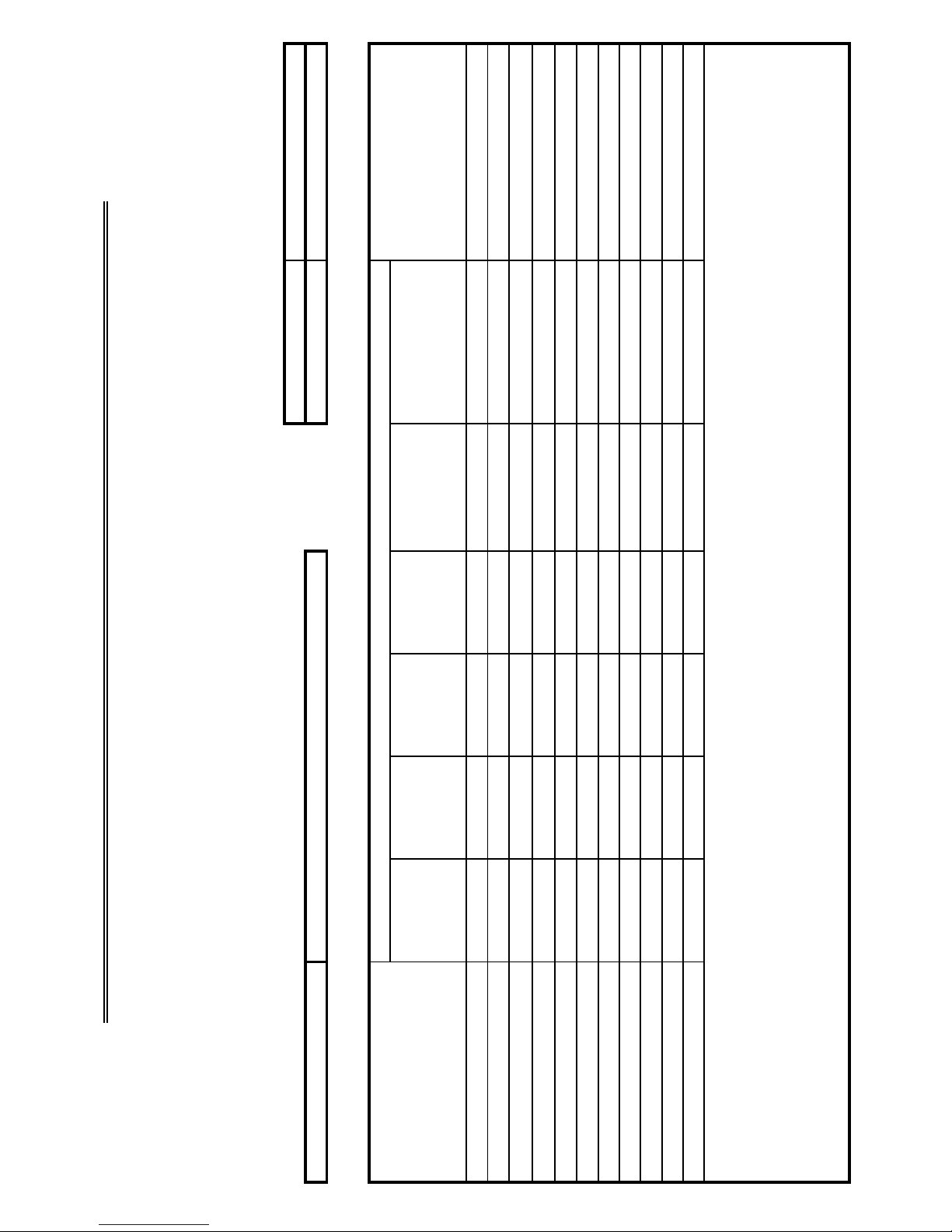
This information sheet was prepared based on People's Republic of China "Management Methods for Controlling Pollution Caused by Electronic Information Products Regulation"and
"SJ/T 11364—2006 Marking for Control of Pollution Caused by Electronic Information Products".
As People's Republic of China "Management Methods for Controlling Pollution Caused by Electronic Information Products Regulation"is a different legislation from EU RoHS Directive
(2002/95/EC), inquiries concerning EU RoHS Directive (2002/95/EC) information should be done separately.
The date of manufacture
Part Name
GENESYS, GEN2.4KW POWER SUPPLY SERIES Product Weight
10Kg
Lead (Pb) Mercury (Hg) Cadmium (Cd) Hexavalent
Chromium (Cr6+)
Polybrominated
Biphenyls (PBB)
Polybrominated Diphenyl
Ethers(PBDE)
0.1wt% 0.1wt% 0.01wt% 0.1wt% 0.1wt% 0.1wt%
Case
O O O O O O
Plastic panel
O O O O O O
PCB's assembly X O O O O O
Inner metal parts O O O O O O
Inner cables O O O O O O
Accessories O O O O O O Provided in the package
○ : Indicates that the concentration values of toxic and hazardous substances in all "homogeneous materials" of respective parts and materials does not exceed the concentration limits
regulated by "SJ/T 11363-2006 Requirements for Concentration Limits for Certain Hazardous Substances in Electronic Information Products".
× : Indicates that the concentration value of a toxic or hazardous substance included in a "homogeneous part" of a respective part ot material exceeds the concentration limit regulated by
"SJ/T 11363-2006 Requirements for Concentration Limits for Certain Hazardous Substances in Electronic Information Products".
Information Concerning Inclusion of Toxic and Hazardous Substances
NotesConcentration Values of Toxic and Hazardous Substances/Elements (wt%)
Subpart Name
(2002/95/EC), inquiries concerning EU RoHS Directive (2002/95/EC) information should be done separately.
The date of manufacture
Part Name
GENESYS, GEN2.4KW POWER SUPPLY SERIES Product Weight
10Kg
Lead (Pb) Mercury (Hg) Cadmium (Cd) Hexavalent
Chromium (Cr6+)
Polybrominated
Biphenyls (PBB)
Polybrominated Diphenyl
Ethers(PBDE)
0.1wt% 0.1wt% 0.01wt% 0.1wt% 0.1wt% 0.1wt%
Case
O O O O O O
Plastic panel
O O O O O O
PCB's assembly X O O O O O
Inner metal parts O O O O O O
Inner cables O O O O O O
Accessories O O O O O O Provided in the package
○ : Indicates that the concentration values of toxic and hazardous substances in all "homogeneous materials" of respective parts and materials does not exceed the concentration limits
regulated by "SJ/T 11363-2006 Requirements for Concentration Limits for Certain Hazardous Substances in Electronic Information Products".
× : Indicates that the concentration value of a toxic or hazardous substance included in a "homogeneous part" of a respective part ot material exceeds the concentration limit regulated by
"SJ/T 11363-2006 Requirements for Concentration Limits for Certain Hazardous Substances in Electronic Information Products".
NotesConcentration Values of Toxic and Hazardous Substances/Elements (wt%)
Subpart Name
Page 5

WARRANTY ..........................................................................................................................................
REGULATORY NOTICES ....................................................................................................................
SAFETY INSTRUCTIONS.....................................................................................................................
GERMAN SAFETY INSTRUCTIONS ...................................................................................................
....................................................................................
1.1 OPERATION MANUAL CONTENT .................................................................................................
1.2 INTRODUCTION .............................................................................................................................
1.2.1 General description ................................................................................................................
1.2.2 Models covered ......................................................................................................................
1.2.3 Features and options .............................................................................................................
1.2.4 Multiple output power system .................................................................................................
1.2.5 Control via the serial communication port ..............................................................................
1.2.6 Analog voltage programming and monitoring .................................................................. ......
1.2.7 Parallel operation ...................................................................................................................
1.2.8 Output connections ................................................................................................................
1.2.9 Cooling and mechanical construction ....................................................................................
1.3 ACCESSORIES ...............................................................................................................................
1.3.1 General ..................................................................................................................................
1.3.2 Serial link cable ......................................................................................................................
1.3.3 Misc. hardware .......................................................................................................................
1.3.4 AC cables ...............................................................................................................................
...................................................................................................
2.1 OUTPUT RATING ...........................................................................................................................
2.2 AUXILIARY OUTPUTS....................................................................................................................
2.3 INPUT CHARACTERISTICS ..........................................................................................................
2.4 CONSTANT VOLTAGE MODE .......................................................................................................
2.5 CONSTANT CURRENT MODE ......................................................................................................
2.6 ANALOG PROGRAMMING AND MONITORING ............................................................................
2.6.1 PROGRAMMING AND READBACK .......................................................................................
2.7 PROTECTIVE FUNCTIONS ...........................................................................................................
2.8 FRONT PANEL ................................................................................................................................
2.9 ENVIRONMENTAL CONDITIONS ..................................................................................................
2.10 MECHANICAL ..............................................................................................................................
2.11 SAFETY/EMC ...............................................................................................................................
2.12 SUPPLEMENTAL CHARACTERISTICS .......................................................................................
2.13 OUTLINE DRAWINGS .................................................................................................................
.......................................................................................................
3.1 GENERAL .......................................................................................................................................
3.2 PREPARATION FOR USE ..............................................................................................................
3.3 INITIAL INSPECTION .....................................................................................................................
3.4 RACK MOUNTING ..........................................................................................................................
3.4.1 To install the power supply in a rack .......................................................................................
3.4.2 Rack mount slides ..................................................................................................................
3.5 LOCATION MOUNTING AND COOLING .......................................................................................
3.6 AC SOURCE REQUIREMENTS .....................................................................................................
3.7 AC INPUT POWER CONNECTION ................................................................................................
3.7.1 AC input connector..................................................................................................................
3.7.2 AC input cord ..........................................................................................................................
3.7.3 AC input wire connection.........................................................................................................
3.8 TURN-ON CHECKOUT PROCEDURE ...........................................................................................
3.8.1 General ...................................................................................................................................
3.8.2 Prior to operation ...................................................................................................................
3.8.3 Constant voltage check ..........................................................................................................
3.8.4 Constant current check ..........................................................................................................
3.8.5 OVP check .............................................................................................................................
3.8.6 UVL check ..............................................................................................................................
3.8.7 Foldback check ......................................................................................................................
3.8.8 Address setting ......................................................................................................................
3.8.9 Baud rate setting ....................................................................................................................
CHAPTER 1 GENERAL INFORMATION
CHAPTER 2 SPECIFICATIONS
CHAPTER 3 INSTALLATION
TABLE OF CONTENTS
Pg.7
Pg.7
Pg.7
Pg.7
Pg.7
Pg.7
Pg.8
Pg.8
Pg.8
Pg.8
Pg.8
Pg.9
Pg.9
Pg.9
Pg.9
Pg.9
Pg.9
Pg.10
Pg.10
Pg.10
Pg.10
Pg.10
Pg.10
Pg.10
Pg.11
Pg.11
Pg.11
Pg.11
Pg.11
Pg.12
Pg.13
Pg.14
Pg.14
Pg.14
Pg.14
Pg.14
Pg.14
Pg.15
Pg.15
Pg.15
Pg.15
Pg.16
Pg.16
Pg.16
Pg.17
Pg.17
Pg.17
Pg.18
Pg.18
Pg.18
Pg.18
Pg.19
Pg.19
Pg.19
Pg.1
Pg.2
Pg.3
Pg.5
Page 6

3.9 CONNECTING THE LOAD ..........................................................................................................
3.9.1 Load Wiring ..........................................................................................................................
3.9.2 Current Carrying Capacity ...................................................................................................
3.9.3 Wire termination .................................................................................................................
3.9.4 Noise and Impedance Effects ..............................................................................................
3.9.5 Inductive loads .....................................................................................................................
3.9.6 Making the load connections ................................................................................................
3.9.7 Connecting single loads, local sensing (default) ..................................................................
3.9.8 Connecting single loads, remote sensing ............................................................................
3.9.9 Connecting multiple loads, radial distribution method ..........................................................
3.9.10 Multiple loads connection with distribution terminals .........................................................
3.9.11 Grounding outputs .............................................................................................................
3.10 LOCAL AND REMOTE SENSING .............................................................................................
3.10.1 Sensing wiring ...................................................................................................................
3.10.2 Local sensing .....................................................................................................................
3.10.3 Remote sensing .................................................................................................................
3.10.4 J2 sense connector technical information ..........................................................................
3.11 REPACKAGING FOR SHIPMENT .............................................................................................
...............
4.1 INTRODUCTION ..........................................................................................................................
4.2 FRONT PANEL CONTROLS AND INDICATORS ........................................................................
4.3 REAR PANEL ...............................................................................................................................
4.3.1 Auxiliary Power Supply..........................................................................................................
4.4 REAR PANEL SW1 SETUP SWITCH .........................................................................................
4.4.1 SW1 positions functions ......................................................................................................
4.4.2 Resetting the switch .............................................................................................................
4.5 REAR PANEL J1 PROGRAMMING AND MONITORING CONNECTOR ....................................
4.5.1 Making J1 connections ........................................................................................................
.............................................................................................
5.1 INTRODUCTION ..........................................................................................................................
5.2 STANDARD OPERATION ............................................................................................................
5.2.1 Constant Voltage Mode .......................................................................................................
5.2.2 Constant Current Operation .................................................................................................
5.2.3 Automatic Crossover ............................................................................................................
5.3 OVER VOLTAGE PROTECTION (OVP) ......................................................................................
5.3.1 Setting the OVP level ..........................................................................................................
5.3.2 Activated OVP protection indications ...................................................................................
5.3.3 Resetting the OVP circuit .....................................................................................................
5.4 UNDER VOLTAGE LIMIT (UVL) ..................................................................................................
5.4.1 Setting the UVL level ...........................................................................................................
5.5 FOLDBACK PROTECTION ..........................................................................................................
5.5.1 Setting the Foldback protection ...........................................................................................
5.5.2. Resetting activated Foldback protection ............................................................................
5.6 OUTPUT ON/OFF CONTROL ......................................................................................................
5.7 OUTPUT SHUT-OFF (SO) CONTROL VIA REAR PANEL J1 CONNECTOR ..............................
5.8 ENABLE/DISABLE CONTROL VIA REAR PANEL J1 CONNECTOR ..........................................
5.9 CV/CC SIGNAL .............................................................................................................................
5.10 PS_OK SIGNAL ..........................................................................................................................
5.11 SAFE START AND AUTO-RESTART MODES ............................................................................
5.11.1 Automatic start mode .........................................................................................................
5.11.2 Safe start mode ..................................................................................................................
5.12 OVER TEMPERATURE PROTECTION (OTP) ..........................................................................
5.13 LAST SETTING MEMORY .........................................................................................................
5.14 SERIES OPERATION .................................................................................................................
5.14.1 Series connection for increased output voltage .................................................................
5.14.2 Series connection for positive and negative output voltage ...............................................
5.15 PARALLEL OPERATION ............................................................................................................
5.16 DAISY-CHAIN CONNECTION ....................................................................................................
5.17 FRONT PANEL LOCKING ..........................................................................................................
CHAPTER 4 FRONT AND REAR
PANEL CONTROLS AND CONNECTORS
CHAPTER 5 LOCAL OPERATION
TABLE OF CONTENTS
Pg.19
Pg.19
Pg.19
Pg.20
Pg.21
Pg.21
Pg.21
Pg.24
Pg.24
Pg.24
Pg.25
Pg.25
Pg.26
Pg.26
Pg.26
Pg.27
Pg.27
Pg.27
Pg.28
Pg.28
Pg.28
Pg.30
Pg.31
Pg.32
Pg.32
Pg.32
Pg.33
Pg.33
Pg.35
Pg.35
Pg.35
Pg.35
Pg.35
Pg.36
Pg.36
Pg.36
Pg.36
Pg.36
Pg.37
Pg.37
Pg.37
Pg.37
Pg.37
Pg.37
Pg.37
Pg.38
Pg.38
Pg.38
Pg.39
Pg.39
Pg.39
Pg.39
Pg.39
Pg.39
Pg.40
Pg.41
Pg.42
Pg.44
Pg.44
Page 7

CHAPTER 6 REMOTE ANALOG PROGRAMMING
.................................................................
6.1 INTRODUCTION ...........................................................................................................................
6.2 LOCAL/REMOTE ANALOG CONTROLL.......................................................................................
6.3 LOCAL/REMOTE ANALOG INDICATION......................................................................................
6.4 REMOTE VOLTAGE PROGRAMMING OF OUTPUT VOLTAGE AND CURRENT LIMIT .............
6.5 RESISTIVE PROGRAMMING OF OUTPUT VOLTAGE AND CURRENT LIMIT ...........................
6.6 REMOTE MONITORING OF OUTPUT VOLTAGE AND CURRENT .............................................
TABLE OF CONTENTS
Pg.45
Pg.45
Pg.45
Pg.45
Pg.46
Pg.47
Pg.48
CHAPTER 6 REMOTE ANALOG PROGRAMMING
CHAPTER 7 RS232 & RS485 REMOTE CONTROL
.................................................................
6.1 INTRODUCTION ...........................................................................................................................
6.2 LOCAL/REMOTE ANALOG CONTROLL.......................................................................................
6.3 LOCAL/REMOTE ANALOG INDICATION......................................................................................
6.4 REMOTE VOLTAGE PROGRAMMING OF OUTPUT VOLTAGE AND CURRENT LIMIT .............
6.5 RESISTIVE PROGRAMMING OF OUTPUT VOLTAGE AND CURRENT LIMIT ...........................
6.6 REMOTE MONITORING OF OUTPUT VOLTAGE AND CURRENT .............................................
...............................................................
7.1 INTRODUCTION ...........................................................................................................................
7.2 CONFIGURATION .........................................................................................................................
7.2.1 Default setting .......................................................................................................................
7.2.2 Address setting .....................................................................................................................
7.2.3 RS232 or RS485 selection ...................................................................................................
7.2.4 Baud rate setting ...................................................................................................................
7.2.5 Setting the unit into Remote or Local mode ..........................................................................
7.2.6 RS232/458 port at Local mode .............................................................................................
7.2.7 Front panel in Remote mode ................................................................................................
7.3 REAR PANEL RS232/485 CONNECTOR ......................................................................................
7.4 CONNECTING POWER SUPPLIES TO RS232 OR RS485 BUS .................................................
7.4.1 Single power supply ..............................................................................................................
7.4.2 Multi power supplies connection to RS232 or RS485 bus ....................................................
7.5 COMMUNICATION INTERFACE PROTOCOL ..............................................................................
7.5.1 Data format ...........................................................................................................................
7.5.2 Addressing ............................................................................................................................
7.5.3 End of message ....................................................................................................................
7.5.4 Command repeat .................................................................................................................
7.5.5 Checksum .............................................................................................................................
7.5.6 Acknowledge .........................................................................................................................
7.5.7 Error message ......................................................................................................................
7.5.8 Backspace ............................................................................................................................
7.6 ERROR MESSAGES .....................................................................................................................
7.7 COMMAND SET DESCRIPTION ..................................................................................................
7.7.1 General guides .....................................................................................................................
7.7.2 Command set categories ......................................................................................................
7.7.3 Initialization control commands .............................................................................................
7.7.4 ID control commands ............................................................................................................
7.7.5 Output control commands .....................................................................................................
7.7.6 Global output commands.......................................................................................................
7.7.7 Status control commands .....................................................................................................
7.8 STATUS, ERROR AND SRQ REGISTERS ...................................................................................
7.8.1 General .................................................................................................................................
7.8.2 Conditional registers .............................................................................................................
7.8.3 Service Request: Enabled and Event Registers ...................................................................
7.9 SERIAL COMMUNICATION TEST SET-UP ..................................................................................
TABLE OF CONTENTS
Pg.45
Pg.45
Pg.45
Pg.45
Pg.46
Pg.47
Pg.48
Pg.49
Pg.49
Pg.49
Pg.49
Pg.49
Pg.49
Pg.49
Pg.49
Pg.50
Pg.50
Pg.50
Pg.51
Pg.51
Pg.52
Pg.52
Pg.52
Pg.52
Pg.52
Pg.52
Pg.52
Pg.52
Pg.53
Pg.53
Pg.53
Pg.53
Pg.53
Pg.53
Pg.54
Pg.54
Pg.54
Pg.56
Pg.57
Pg.58
Pg.58
Pg.58
Pg.59
Pg.62
CHAPTER 6 REMOTE ANALOG PROGRAMMING
CHAPTER 7 RS232 & RS485 REMOTE CONTROL
CHAPTER 8 ISOLATED ANALOG PROGRAMMING OPTION
.................................................................
6.1 INTRODUCTION ...........................................................................................................................
6.2 LOCAL/REMOTE ANALOG CONTROLL.......................................................................................
6.3 LOCAL/REMOTE ANALOG INDICATION......................................................................................
6.4 REMOTE VOLTAGE PROGRAMMING OF OUTPUT VOLTAGE AND CURRENT LIMIT .............
6.5 RESISTIVE PROGRAMMING OF OUTPUT VOLTAGE AND CURRENT LIMIT ...........................
6.6 REMOTE MONITORING OF OUTPUT VOLTAGE AND CURRENT .............................................
...............................................................
7.1 INTRODUCTION ...........................................................................................................................
7.2 CONFIGURATION .........................................................................................................................
7.2.1 Default setting .......................................................................................................................
7.2.2 Address setting .....................................................................................................................
7.2.3 RS232 or RS485 selection ...................................................................................................
7.2.4 Baud rate setting ...................................................................................................................
7.2.5 Setting the unit into Remote or Local mode ..........................................................................
7.2.6 RS232/458 port at Local mode .............................................................................................
7.2.7 Front panel in Remote mode ................................................................................................
7.3 REAR PANEL RS232/485 CONNECTOR ......................................................................................
7.4 CONNECTING POWER SUPPLIES TO RS232 OR RS485 BUS .................................................
7.4.1 Single power supply ..............................................................................................................
7.4.2 Multi power supplies connection to RS232 or RS485 bus ....................................................
7.5 COMMUNICATION INTERFACE PROTOCOL ..............................................................................
7.5.1 Data format ...........................................................................................................................
7.5.2 Addressing ............................................................................................................................
7.5.3 End of message ....................................................................................................................
7.5.4 Command repeat .................................................................................................................
7.5.5 Checksum .............................................................................................................................
7.5.6 Acknowledge .........................................................................................................................
7.5.7 Error message ......................................................................................................................
7.5.8 Backspace ............................................................................................................................
7.6 ERROR MESSAGES .....................................................................................................................
7.7 COMMAND SET DESCRIPTION ..................................................................................................
7.7.1 General guides .....................................................................................................................
7.7.2 Command set categories ......................................................................................................
7.7.3 Initialization control commands .............................................................................................
7.7.4 ID control commands ............................................................................................................
7.7.5 Output control commands .....................................................................................................
7.7.6 Global output commands.......................................................................................................
7.7.7 Status control commands .....................................................................................................
7.8 STATUS, ERROR AND SRQ REGISTERS ...................................................................................
7.8.1 General .................................................................................................................................
7.8.2 Conditional registers .............................................................................................................
7.8.3 Service Request: Enabled and Event Registers ...................................................................
7.9 SERIAL COMMUNICATION TEST SET-UP ..................................................................................
..............................................
8.1 INTRODUCTION ...........................................................................................................................
8.2 SPECIFICATIONS .........................................................................................................................
8.2.1 0-5V/0-10V option .................................................................................................................
8.2.2 4-20mA option .......................................................................................................................
8.3 ISOLATED PROGRAMMING & MONITORING CONNECTOR ....................................................
8.4 SETUP AND OPERATING INSTRUCTIONS .................................................................................
8.4.1 Setting up the power supply for 0-5/0-10V Isolated Programming and Monitoring ...............
8.4.2 Setting up the power supply for 4-20mA Isolated Programming and Monitoring ..................
TABLE OF CONTENTS
Pg.45
Pg.45
Pg.45
Pg.45
Pg.46
Pg.47
Pg.48
Pg.49
Pg.49
Pg.49
Pg.49
Pg.49
Pg.49
Pg.49
Pg.49
Pg.50
Pg.50
Pg.50
Pg.51
Pg.51
Pg.52
Pg.52
Pg.52
Pg.52
Pg.52
Pg.52
Pg.52
Pg.52
Pg.53
Pg.53
Pg.53
Pg.53
Pg.53
Pg.53
Pg.54
Pg.54
Pg.54
Pg.56
Pg.57
Pg.58
Pg.58
Pg.58
Pg.59
Pg.62
Pg.63
Pg.63
Pg.63
Pg.63
Pg.63
Pg.64
Pg.65
Pg.65
Pg.65
CHAPTER 6 REMOTE ANALOG PROGRAMMING
CHAPTER 7 RS232 & RS485 REMOTE CONTROL
CHAPTER 8 ISOLATED ANALOG PROGRAMMING OPTION
CHAPTER 9 MAINTENANCE
.................................................................
6.1 INTRODUCTION ...........................................................................................................................
6.2 LOCAL/REMOTE ANALOG CONTROLL.......................................................................................
6.3 LOCAL/REMOTE ANALOG INDICATION......................................................................................
6.4 REMOTE VOLTAGE PROGRAMMING OF OUTPUT VOLTAGE AND CURRENT LIMIT .............
6.5 RESISTIVE PROGRAMMING OF OUTPUT VOLTAGE AND CURRENT LIMIT ...........................
6.6 REMOTE MONITORING OF OUTPUT VOLTAGE AND CURRENT .............................................
...............................................................
7.1 INTRODUCTION ...........................................................................................................................
7.2 CONFIGURATION .........................................................................................................................
7.2.1 Default setting .......................................................................................................................
7.2.2 Address setting .....................................................................................................................
7.2.3 RS232 or RS485 selection ...................................................................................................
7.2.4 Baud rate setting ...................................................................................................................
7.2.5 Setting the unit into Remote or Local mode ..........................................................................
7.2.6 RS232/458 port at Local mode .............................................................................................
7.2.7 Front panel in Remote mode ................................................................................................
7.3 REAR PANEL RS232/485 CONNECTOR ......................................................................................
7.4 CONNECTING POWER SUPPLIES TO RS232 OR RS485 BUS .................................................
7.4.1 Single power supply ..............................................................................................................
7.4.2 Multi power supplies connection to RS232 or RS485 bus ....................................................
7.5 COMMUNICATION INTERFACE PROTOCOL ..............................................................................
7.5.1 Data format ...........................................................................................................................
7.5.2 Addressing ............................................................................................................................
7.5.3 End of message ....................................................................................................................
7.5.4 Command repeat .................................................................................................................
7.5.5 Checksum .............................................................................................................................
7.5.6 Acknowledge .........................................................................................................................
7.5.7 Error message ......................................................................................................................
7.5.8 Backspace ............................................................................................................................
7.6 ERROR MESSAGES .....................................................................................................................
7.7 COMMAND SET DESCRIPTION ..................................................................................................
7.7.1 General guides .....................................................................................................................
7.7.2 Command set categories ......................................................................................................
7.7.3 Initialization control commands .............................................................................................
7.7.4 ID control commands ............................................................................................................
7.7.5 Output control commands .....................................................................................................
7.7.6 Global output commands.......................................................................................................
7.7.7 Status control commands .....................................................................................................
7.8 STATUS, ERROR AND SRQ REGISTERS ...................................................................................
7.8.1 General .................................................................................................................................
7.8.2 Conditional registers .............................................................................................................
7.8.3 Service Request: Enabled and Event Registers ...................................................................
7.9 SERIAL COMMUNICATION TEST SET-UP ..................................................................................
..............................................
8.1 INTRODUCTION ...........................................................................................................................
8.2 SPECIFICATIONS .........................................................................................................................
8.2.1 0-5V/0-10V option .................................................................................................................
8.2.2 4-20mA option .......................................................................................................................
8.3 ISOLATED PROGRAMMING & MONITORING CONNECTOR ....................................................
8.4 SETUP AND OPERATING INSTRUCTIONS .................................................................................
8.4.1 Setting up the power supply for 0-5/0-10V Isolated Programming and Monitoring ...............
8.4.2 Setting up the power supply for 4-20mA Isolated Programming and Monitoring ..................
......................................................................................................
9.1 INTRODUCTION ...........................................................................................................................
9.2 UNITS UNDER WARRANTY .........................................................................................................
9.3 PERIODIC MAINTENANCE ..........................................................................................................
9.4 ADJUSTMENT AND CALIBRATION .............................................................................................
9.5 PARTS REPLACEMENT AND REPAIRS .......................................................................................
9.6 TROUBLESHOOTING ...................................................................................................................
9.7 FUSE RATING ...............................................................................................................................
CHAPTER 9 GERMAN TRANSLATION.........................................................................................
USER MANUAL INDEX .......................................................................................................................
TABLE OF CONTENTS
Pg.45
Pg.45
Pg.45
Pg.45
Pg.46
Pg.47
Pg.48
Pg.49
Pg.49
Pg.49
Pg.49
Pg.49
Pg.49
Pg.49
Pg.49
Pg.50
Pg.50
Pg.50
Pg.51
Pg.51
Pg.52
Pg.52
Pg.52
Pg.52
Pg.52
Pg.52
Pg.52
Pg.52
Pg.53
Pg.53
Pg.53
Pg.53
Pg.53
Pg.53
Pg.54
Pg.54
Pg.54
Pg.56
Pg.57
Pg.58
Pg.58
Pg.58
Pg.59
Pg.62
Pg.63
Pg.63
Pg.63
Pg.63
Pg.63
Pg.64
Pg.65
Pg.65
Pg.65
Pg.66
Pg.66
Pg.66
Pg.66
Pg.66
Pg.66
Pg.66
Pg.67
Pg.68
Pg.71
Page 8

This page intentionaly left blank
Page 9

This Nemic-Lambda product is warranted against defects in materials and workmanship for a period
of five years from date of shipment .During the warranty period, Nemic-Lambda will, at it’soption,
either repair or replace products which prove to be defective.
The warranty shall not apply to defects resulting from improper or inadequate usage or maintenance
by the buyer, buyer supplied products or interfacing. The warranty shall not apply to defects resulting
from unauthorized modifications or from operation exceeding the environmental specifications of
the product or if the QA seal has been removed or altered by anyone other than Nemic-Lambda
authorised personnel. Nemic-Lambda does not warrant the buyers circuitry or malfunctions of
Nemic-Lambda products resulting from the buyer’s circuitry. Furthermore, Nemic-Lambda does not
warrant any damage occurring as a result of the buyer’s circuitry or the buyer’s - supplied products.
This product must be returned to an authorized Nemic-Lambda service facility for repairs or other
warranty service. For products returned to Nemic_Lambda for warranty service, the buyer shall
prepay shipping charges to Nemic-Lambda and Nemic-Lambda shall pay the shipping charges to
return the product to the buyer. Refer to section3.11 for repackaging for shipment.
The information contained in this document is subject to change without notice. Nemic-Lambda
shall not be liable for errors contained in this document or for incidental or consequential damages in
connection with the furnishing, performance or use of this material. No part of this document may be
photocopied, reproduced or translated into another language without the prior written consent of
Nemic-Lambda.
Microsoft and Windows are trademarks of Microsoft Corporation.
WARRANTY
LIMITATION OF WARRANTY
WARRANTY SERVICE
DISCLAIMER
TRADEMARK INFORMATION
No other warranty is expressed or implied.
TM TM
Genesys power supply is a trademark of Nemic-Lambda & Lambda Americas Inc.
TM
1
Page 10

REGULATORY NOTICES
FCC Notice
This device complies with Part 15 of the FCC Rules. Operation is subject to the following two
conditions: (1) this device may not cause harmful interference, and (2) this device must accept any
interference received, including interference that may cause undesired operation.
CE Notice (European Union)
Marking by the CE Symbol indicates compliance to the EMC Directive and the Low Voltage
Directive of the European Union. Such marking is indicative that the Genesys series
GEN2400W meets the following technical standards:
EN 55022:2007+A1:2009 -”Limits and Methods of Measurement of Radio Interference
Characteristics of Information Technology Equipment.”
EN 55024:1998+A1:2001+A2:2003-”information thecnology equipment - Immunity
characteristics - Limits and methods of measurement.”
EN 60950-1:2006+A11:2009 - “Safety of Information Technology Equipment.”
A “Declaration of Conformity” in accordance with the preceding directives and standards has been
made and is on file at our EU representative TDK-Lambda Limited, located at Kingsley Avenue,
Ilfracombe, Devon EX34 8ES, UK.
TM
•
•
•
NOTE: This equipment has been tested and found to comply with the limits for a Class A digital
device, pursuant to Part 15 of the FCC Rules. These limits are designed to provide reasonable
protection against harmful interference when the equipment is operated in a commercial
environment. This equipment generates, uses, and can radiate radio frequency energy and, if not
installed and used in accordance with the instruction manual, may cause harmful interference to
radio communications. Operation of this equipment in a residential area is likely to cause harmful
interference in which case the user will be required to correct the interference at his own expense.
WARNING:
Modifications not expressly approved by the party responsible for compliance could
void the user’s authority to operate the equipment under FCC Rules.
WARNING: This is a Class A product. on a domestic environment this product may cause radio
interference in which case user may be required to take adequate measures.
SAFETY APPROVALS: UL 60950-1:2007 Second Edition, UL Listed, C-UL for Canada, IEC
60950-1:2005 Second Edition, CE marking, when applied to the GEN2400W product, indicates
compliance with the Low Voltage Directive 2006/95/EC in that it complies with EN 609501:2006/A11:2009.
2
Page 11
SAFETY INSTRUCTIONS
CAUTION
INSTALLATION CATEGORY
GROUNDING
FUSES
INPUT RATINGS
LIVE CIRCUITS
PARTS SUBSTITUTIONS & MODIFICATIONS
The following safety precaution must be observed during all phases of operation, service and repair
of this equipment. Failure to comply with the safety precautions or warnings in this document
violates safety standards of design, manufacture and intended use of this equipment and may
impair the built-in protections within.
Nemic-Lambda shall not be liable for user’s failure to comply withthese requirements.
The Genesys power supply series has been evaluated to INSTALLATION CATEGORY II.
Installation category (over voltage category) II: local level, appliances, portable equipment etc.. With
smaller transient over voltage than Installation Category (over voltage category) III.
This product is a Safety Class 1 instrument. To minimize shock hazard, the instrument chassis must
be connected to an electrical ground. The instrument must be connected to the AC power supply
mains through a three conductor power cable for Single Phase models and through a four conductor
power cable for Three Phase models with the ground wire firmly connected to an electrical ground
(safety ground) at the power outlet.
For instruments designed to be hard-wired to the supply mains, the protective earth terminal must
be connected to the safety electrical ground before another connection is made.Any interruption of
the protective ground conductor, or disconnection of the protective earth terminal will cause a
potential shock hazard that might cause personal injury.
There is a potential shock hazard at the RS232/485 and the IEEE portswhen using power supplies
with rated or combined voltage greater than 400V and the Positive Output of the Power Supply is
grounded. Do Not connect the Positive Output to ground when using the RS232/485 or IEEE.
Fuses must be changed by authorized Nemic-Lambda service personnel only. For continued
protection against risk of fire, replace only with the same type and rating of fuse. Refer to
maintenance instructions in chapter 9 for fuses rating.
The Genesys power supply units have fuses in all supply conductots. To prevent potential risk of
hazard during servicing, the unit shall be fully disconnected from the supply.
Do not use AC supply which exceeds the input volt
age and frequency rating of this instrument. The
input voltage and frequency rating of the Genesys power supply series is:190-240V~, 50/60Hz for
Three Phase 200V models and 380-415V~, 50/60Hz for Three Phase 400V models. For safety
reasons, the mains supply voltage fluctuations should not exceed +/-10% of nominal voltage.
Operating personnel must not remove the instrument cover. No internal adjustment or component
replacement is allowed bynon-Nemic-Lambda qualified personnel. Never replace components with
power cable connected. To avoid injuries, always disconnect power , discharge circuits and remove
external voltage source before touching components.
Parts substitutions and modifications are allowed by authorized Nemic-Lambda service personnel
only. For repairs or modifications, the instrument must be returned to Nemic-Lambda service facility.
TM
TM
TM
WARNING
OUTPUT TERMINAL GROUNDING
CAUTION MULTI POLE FUSING
3
Page 12
SAFETY INSTRUCTIONS.
ENVIRONMENTAL CONDITIONS
The Genesys power supply series safety approval applies to the following operating conditions:
*Indoor use *Ambient temperature: 0 C to 50 C
*Maximum relative humidity: 90% (no condensation) *Altitude: up to 3000m
*Pollution degree 2
TM
o o
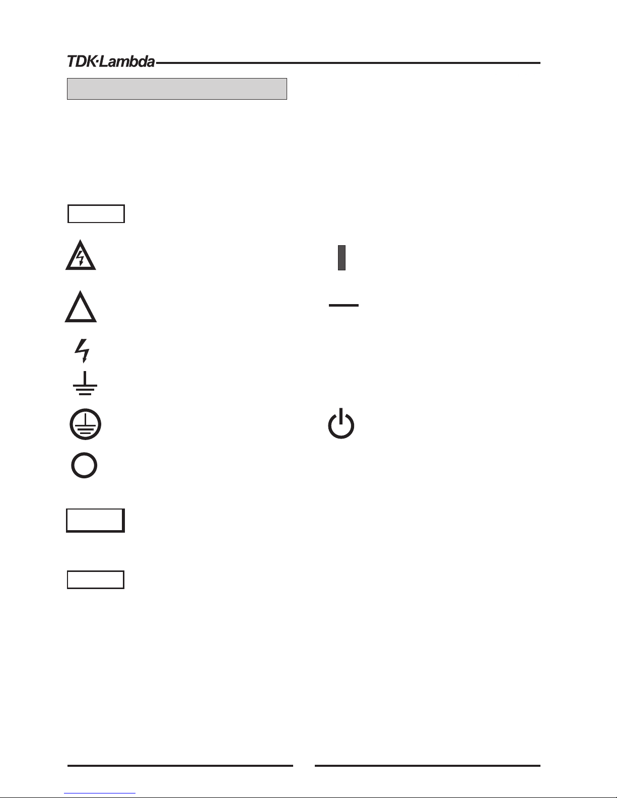
!
Instruction manual symbol. The
instrument will be marked with this
symbol when it is necessary for the
user to refer to the instruction
manual.
CAUTION Risk of Electrical Shock.
Indicates hazardous voltage.
Indicates ground terminal.
Protective Ground Conductor Terminal
Off (Supply)
On (Supply)
Direct Current (DC)
Alternative Current (AC)
Three-PhaseAlternating Current
Standby (Supply)
The WARNING sign denotesa hazard.An attention to aprocedure is called.
Not following procedure correctly could result in personal injury.
AWARNING sign should not beskipped and all indicated conditions must be
fully understood and met.
The CAUTION sign denotes a hazard. An attention to a procedure is called. Not
following procedure correctly could result in damage to the equipment. Do not proceed
beyond a CAUTION sign until all indicated conditions are fully understood and met.
Do not use this product in environments with strong Electromagnetic field, corrosive
gas and conductive materials.
WARNING
CAUTION
CAUTION
3~
-
-
-
~
4
Page 13
SICHERHEITS-INSTALLATIONS ANWEISUNGEN
Vorsicht
Betriebsbedingungen
Erdungskonzept
Vorsicht
Absicherung
Anschluss an Versorgungsstromkreis
Die Genesys Stromversorgungs-Reihe ist zur Installation gemäss Überspannungs-Kategorie 2
entwickelt worden.
Installations Kategorie (Überspannungs-Kategorie) 2 bedeutet: Kleinindustrie, Geräte,
bewegliche Ausr stung etc.. mit Überspannungen kleiner als Installation Kategorie 3.
Die Genesys Stromversorgungen sind zur Installation in geschlossenen Gehäusen
vorgesehen. Personenkontakt zu spannungsführenden Teilen (auf der Rückseite der
Stromversorgung) muß durch fachgerechte Montage verhindert werden.
Dieses Produkt ist ein Gerät mit Schutzklasse1. Damit gefährliche Energieinhalte und
Spannungen vermieden werden, ist das Gerätechassis an eine Schutzerde anzuschliessen. Das
1-phasige Gerät muss an die AC-Wechselspannungsversorgung mit 3 Leitern (L, N, PE) und das
3-phasige Gerät mit 4 Leitern (L1, L2, L3, PE) angeschlossen werden. Der PE-Anschluss ist an
einen festen Erder anzuschliessen. Bei Festverdrahtung des Gerätes ist sicherzustellen, dass
der PE Anschluss als erstes durchgef hrt wird.
Jede mögliche Unterbrechung des PE-Leiters oder Trennung der PE Masse kann einen
möglichen elektrischen Schlag hervorrufen, der Personenschäden zur Folge hätte.
Es besteht Energiegefahr am RS232/485 und IEEE Anschluss, falls die Ausgangsspannung des
Gerätes grösser ist als 400V und der positive Ausgangsanschluss des Netzteiles geerdet wird.
Dies gilt insbesondere auch bei Reihenschaltungen von unterschiedlichen Netzteilen. Wird die
RS232/485 oder IEEE Schnittstelle verwendet, ist darauf zu achten, dass der
Plus-Ausgangsanschluss nicht geerdet wird.
Sicherungen d rfen nur durch autorisierte Nemic-Lambda Service Personen ausgetauscht
werden. Um Brandgefahr vorzubeugen, sind nur Sicherungen zu verwenden mit gleicher Bauart
und Auslösecharakteristik. Siehe hierzu Wartungsanweisungen in Kapitel 9 bez glich
Sicherungen.
Der Betrieb des Gerätes ist nur für den dafür spezifizierten Wechselspannungsbereich und der
angegebenen Frequenz erlaubt.
Der Nominaleingangsspannungsbereich der Genesys Serie liegt bei 190-240VAC mit 50/60Hz.
F r 3-phasige Geräte mit nom. 200VAC, bzw. 380-415VAC 50/60Hz fur 3-phasige Geräte mit
nom. 400VAC.
TM
TM
TM
Erdung des DC-Ausgangs
!
WARNING
ACHTUNG NETZSICHERUNGEN
Das Genesys Netzteil hat in allen Versorgungsleitern Sicherungen. Um Gef hrdungen
w hrend der W rtung des Produktes zu vermiden muß das Produkt vollständig vom
Versorgungsnetz abgesteckt werden.
TM
ä a
Die folgenden Sicherheitsvorschriften müssen vor Inbetriebnahme und in jedem Betriebsstadium bei
Service oder Reparatur beachtet werden. Mißachtung der Sicherheitsvorschriften und Warnhinweise aus
diesem Handbuch führen zur Verletzung der bestehenden Sicherheitsstandards. Bei Betrieb des Gerätes
außerhalb dem bestimmungsgemäßen Einsatz können die im Gerät integrierten Sicherheitsmaßnahmen
beeinträchtigt werden. Lambda ist nicht haftbar für Schäden, die durch Mißachtung dieser
Sicherheitsvorschriften entstehen können.
5
Page 14
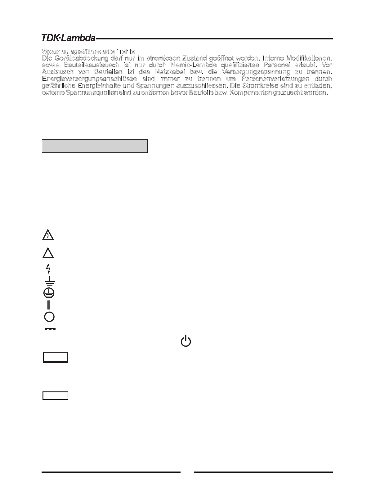
Änderungen und Bauteileersatz
Umweltbedingungen
Sicherheits- und Warnsymbole
Ersatzteilaustausch - und Änderungen dürfen nur von autorisiertem Nemic-Lambda SERVICEPERSONEN durchgeführt werden. Für Reparaturen oder nderungen ist das Gerät zur NemicLambda Service-Niederlassung zu retournieren.
Die Genesys -Stromversorgungs-Serie ist gemäss den Sicherheitsabnahmen für folgende
Betriebsbedingungen zugelassen.
* Stationäre Einrichtungen in Gebäuden.
* Umgebungstemperaturbereich: 0-50 C.
* Maximale Relative Luftfeuchtigkeit: 90% (nicht kondensierend).
* Betriebshöhe: bis zu 3000m.
* Verschmutzungsgrad 2.
VORSICHT Spannungsführende Teile - Gefahr durchelektrischen Schlag bzw.Energieinhalte.
Handbuch-Symbol. Das Gerät bzw. Geräteteile werden mit diesem Symbol gekennzeichnet,
wenn es für den Benutzer notwendig ist, sich auf die Anweisungenim Handbuch zu beziehen.
Zeigt "spannungsführende Teile" mit gefährlicher Spannung an.
Zeigt Masse-Anschluss an, keine Schutzerde.( z.B. Masseanschluss an einen Verbraucher).
Schutzleiter-Anschlussklemme.
Symbol für Schalter oder Druckknöpfe - Zeigt die "Ein"- Stellung hier an.
Symbol für Schalter oder Druckknöpfe - Zeigt die "Aus"-Stellung hier an.
Gleichspannung (DC)
Wechselspannung (AC)
Diese Warnaufschrift weist auf eine Gefahr hin, die eine Überprüfungsanweisung nach
sich zieht. Nichteinhaltung kann zu Personenschäden führen.
Dieser Warnhinweis darf nicht übersprungen werden und die beschriebene Vorgehensweise muss
strikt verstanden werden und dementsprechend umgesetzt werden.
Diese "Vorsichtswarnung" weist auf eine Gefahr hin, die einer Vorkehrung bedarf.
Nichteinhaltung kann zur Zerstörung der Anlage oder des Gerätes führen. Bitte berücksichtigen
Sie Anweisungen, die dort beschrieben sind, bevor Sie mit der Benutzung der Anlage bzw.
des Gerätes fortfahren.
SICHERHEITS-HINWEISE
TM
o
alle
3-phasen Wechselspannung
Symbol für Bereitschaft (Standby)
WARNING
CAUTION
!
3~
~
Spannungsf hrende Teile
Die Geräteabdeckung darf nur im stromlosen Zustand geöffnet werden. Interne Modifikationen,
sowie Bauteileaustausch ist nur durch Nemic-Lambda qualifiziertes Personal erlaubt. Vor
Austausch von Bauteilen ist das Netzkabel bzw. die Versorgungsspannung zu trennen.
Energieversorgungsanschlüsse sind immer zu trennen um Personenverletzungen durch
gefährliche Energieinhalte und Spannungen auszuschliessen. Die Stromkreise sind zu entladen,
externe Spannunsquellensind zuentfernenbevor Bauteile bzw.Komponenten getauschtwerden.
MASCHINENLAERM
Maschinenlaerminformations Verordnung 3. GPSGV, der hoechste Schalldruckpegel betraegt
70 dB A) oder weniger gemass EN ISO 7779.
– –
(
6
Page 15

CHAPTER 1 GENERAL INFORMATION
1.1 USER MANUAL CONTENT
1.2 INTRODUCTION
This user’s manual contains the operating instructions, installation instructions and specifications of
the Genesys 2400W power supply series. The instructions refer to the standard power supplies,
including the built-in RS232/485 serial communication. For information related to operation with the
optional LAN/IEEE programming, refer to User Manual for Power Supply LAN/IEEE Programming
Interface.
Genesys power supplies are wide output range, high performance switching power supplies. The
Genesys series is power factor corrected and operates from worldwide AC voltage range. Output
voltage and current are continuously displayed and LED indicators show the complete operating
status of the power supply.The Front panel controls allow the user to set the output parameters, the
protection levels (Over-Voltage protection, Under-Voltage limit and Foldback) and preview the
settings. The rear panel includes the necessary connectors to control and monitor the power supply
operation by remote analog signals or by the built-in serial communication (RS232/485). LAN/IEEE
programming and Isolated-Analog programming/monitoring are optional.
Models with rated output from 0-8VDC/0-300A to 0-600VDC/0-4A.
Constant Voltage / Constant Current with automatic crossover.
* Active Power Factor correction.
* Single Phase or Three Phase options.
* Embedded Microprocessor Controller.
* Built in RS232/485 Interface.
* Voltage & Current high resolution adjustment by digital encoders.
* High accuracy programming/readback-16 bit.
* Software Calibration (no internal trimmers / potentiometers).
* Last Setting Memory.
* Independent Remote ON/OFF (opto-isolated) and Remote Enable/Disable.
TM
TM
TM
1.2.1 General description
1.2.2 Models covered by this manual
1.2.3 Features and options
*
7
Page 16

* Parallel operation (Master/Slave) with Active current sharing.
* Remote sensing to compensate for voltage drop of power leads.
* Cooling fan speed control for low noise and extended fan life.
* Zero stacking- no ventillation holes at the top and bottom surface of the power supply.
* Optional GPIB interface (SCPI compatible).
* Optional Isolated Analog programming/monitoring (0-5V or 0-10V, user selectable
and 4-20mA).
The Genesys power supplies series can be configured into a programmable power
system of up to 31 units using the built-in RS232/RS485 communication port in the power
supply and the RS485 linking cable provided with each power supply.
In a GPIB system, each power supply can be controlled using the optional GPIB controller
(factory installed).
The following parameters can be programmed via the serial communication port:
1. Output voltage setting.
2. Output current setting.
3. Output voltage measurement.
4. Output on/off control.
5. Output current measurement.
6. Foldback protection setting.
7. Over-voltage protection setting and readback.
8. Under-Voltage limit setting and readback.
9. Power-supply start up mode (last setting or safe mode)
Analog inputs and outputs are provided at the rear panel for analog control of the power
supply. The output voltage and the current limit can be programmed by analog voltage or by
resistor,and can be monitored by analog voltage. The power supply output can be remotely
set to On or Offand analog signals monitor the proper operation of the power supply and the
mode of operation (CV/CC).
Genesys power supplies of the same output voltageand current rating can be paralleled in
master-slave configuration with automatic current sharing to increase power available.
Output connections are made to rear panel bus-bars for models up to 100V and to a 4terminal wire clamp connector for models above 100V rated output voltage. Either the
positive or negative terminal may be grounded or the output may be floated. Models up to
60VDC Rated Output shall not float outputs more than +/- 60VDC above/below chassis
ground. Models >60VDC Rated Output shall not float outputs more than +/-600VDC
above/below chassis ground. Contact factory for assistance with higher float voltage
applications.
Local or remote sense may be used.
In remote sense, the voltage drop on the load wires
should be minimized. Refer to the specifications for the maximum voltage drop value.
* External Analog Programming and Monitoring standard (0-5V or 0-10V, user selectable).
1.2.4 Multiple output power system
1.2.5 Control via the serial communication port
1.2.6 Analog voltage programming and monitoring
1.2.7 Parallel operation
TM
TM
1.2.8 Output connections
8
Page 17
1.2.9 Cooling and mechanical construction
1.3.1 General
1.3.2 Serial link cable
1.3.4 AC cables
The Genesys series is cooled by internal fans. At the installation, care must be taken to
allow free air flow into the power supply via the front panel and out of the power supply via
the rear panel. The Genesys power supplies have a compact and lightweight package
which allows easy installation and space saving in the application equipment.
Accessories are delivered with the power supply or separately upon ordering. The list below
shows the possible accessories and ordering numbers.
S
TM
TM
1.3 ACCESSORIES
erial link cable, for linking power supplies by RS485 communication is provided with the
power supply.
Cable description: 0.5m length, shielded, RJ-45 type plugs, 8 contacts (P/N: GEN/RJ45).
* Output terminal shield
AC cables are not provided with the power supply.
Refer to Table1-1 for recommended AC input cables (customer supplied). Add a non-locking
plug approved by the national safety standards of the country of usage.
1.3.3 Misc. hardware
* Strain relief for AC cord
* DB25 plug kit (AMP, 749809-9)
* Connector plug kit, (Phoenix Contact, plug:IMC 1,5/7-ST-3,81, Header: IMC 1,5/7-G-3,81)
Observe all torque guidelines within this manual. Over torqueing may damage
unit or accessories. Such damage is not covered under manufacturers warranty.
CAUTION
Min 3x12AWG (3 wire plus safety ground),
stranded copper, 300V, 60 c minimum, rated for
25A. 3m max. length, outer diameter: 9~11mm.
O
Min 4x14AWG (3 wire plus safety ground),
stranded copper, 600V, 60 c minimum, rated for
15A. 3m max. length, outer diameter: 9~11mm.
O
190-240V~ , Single Phase
190-240V~ , Three Phase
AC Input Range
AC Input Cable
Table 1-1: Recommended AC input cable
9
Page 18
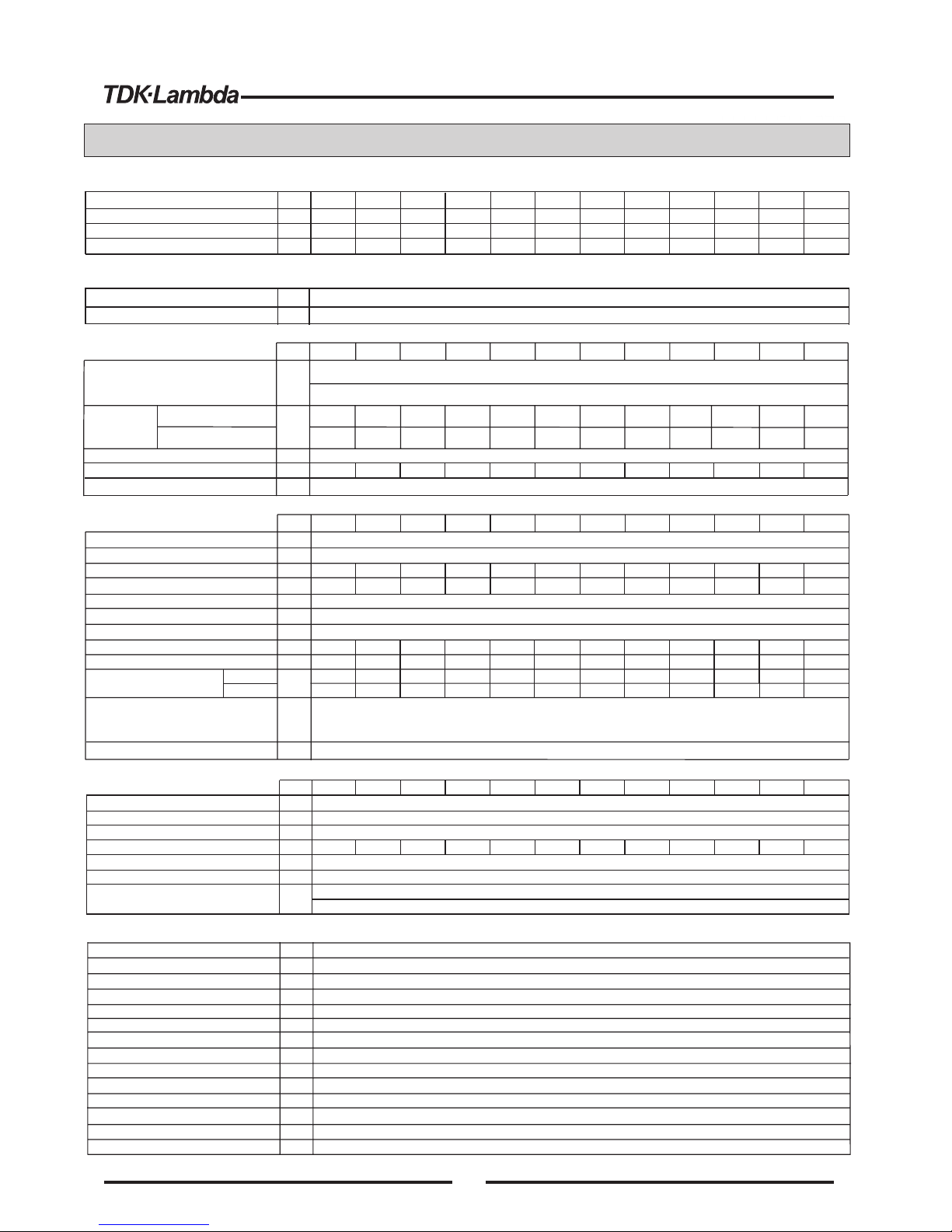
CHAPTER 2 SPECIFICATIONS
1.Vout voltage programming
2.Iout voltage programming (*13)
3.Vout resistor programming
4.Iout resistor programming (*13
5.On/off control
6.Output current monitor (*13)
7.Output voltage monitor
8.Power supply OK signal
9.Parallel operation
10.Series operation
11.CV/CC indicator
12.Enable/Disable
13.Local/Remote analog control
14.Local/Remote analog indicator
)
2.6 ANALOG PROGRAMMING AND MONITORING
---
---
---
---
---
---
---
---
---
---
---
---
---
---
0~100%, 0~5V or 0~10V, user selectable. Accuracy and linearity: +/-0.5% of rated Vout.
0~100%, 0~5V or 0~10V, user selectable. Accuracy and linearity: +/-1% of rated Iout.
0~100%, 0~5/10Kohm full scale, user selectable. Accuracy and linearity: +/-1% of rated Vout.
0~100%, 0~5/10Kohm full scale, user selectable. Accuracy and linearity: +/-1.5% of rated Iout.
By electrical Voltage: 0~0.6V/2~15V or dry contact, user selectable logic.
0~5V or 0~10V, user selectable. Accuracy: +/-1%.
0~5V or 0~10V, user selectable. Accuracy : +/-1%.
4~5V-OK, 0V-Fail. 500ohm series resistance.
Possible , up to 4 units in master/slave mode with two wires current balance connection.
Possible (with external diodes), up to 2 units. 600Vdc max.from chassis ground.
Open collector. CC mode: On, CV mode: Off. Maximum voltage : 30V, maximum sink current: 10mA
Dry contact. Open: Off, Short: On. Max. voltage at Enable/Disable in: 6V.
By electrical signal or Open/Short: 0~0.6V or short: Remote, 2~15V or open: Local.
Open collector. Local: Open, Remote: On. Maximum voltage: 30V, maximum sink current: 10mA.
2.1 OUTPUT RATING
1.Rated output voltage(1*)
2.Rated output current (*2)
3.Rated output power
V
A
W
MODEL
GEN
8-300
8
300
2400
10-240
10
240
2400
16-150
16
150
2400
20-120
20
120
2400
30-80
30
80
2400
40-60
40
60
2400
60-40
60
40
2400
80-30
80
30
2400
100-24
100
24
2400
150-16
150
16
2400
300-8
300
8
2400
600-4
600
4
2400
V
8
10
16
20
40
30
60
80
100
150
600
300
2.5 CONSTANT CURRENT MODE
1.Max. Line regulation (*6)
2.Max. Load regulation (*11)
3.Load regulation thermal drift
4.Ripple r.m.s. 5Hz~1MHz (*12)
5.Temperature coefficient
6.Temperature stability
7.Warm-up drift
---
---
---
---
---
mA
PPM/ C
o
0.01% of rated output current + 2mA
0.02% of rated output current + 5mA
100PPM/ C from rated output current, following 30 minutes warm-up.
0.05% of rated Iout over 8hrs interval following 30 minutes warm-up. Constant line, load & temperature.
O
Less than 0.05% of rated output current over 30 minutes following load change.
900
600
480
1200
120
220 30
40
70
50
15
7
8~16V model: Less than +/-0.2% of rated output current over 30 minutes following power on.
20V~600V model: Less than +/-0.1% of rated output current over 30 minutes following power on.
2.3 INPUT CHARACTERISTICS
1-Phase, 200V models:
3-Phase, 200V models:
---
--%
3-Phase models: 0.94 @ 230Vac, 1-Phase models: 0.99 @ 230Vac, rated output power.
1-Phase models: 170~265Vrms, 47~63Hz
3-Phase models: 170~265Vrms, 47~63Hz
Less than 50A
V
8
10
16
20
30
60
40 150
100
80
600
300
17.3
10.5
17.3
10.5
17.3
10.5
16.6
10.1
16.6
10.1
16.7
10.1
16.8
10.2
16.6
10.1
16.6
10.1
16.6
10.1
16.6
10.1
16.6
10.1
3.Power Factor (Typ)
4.Efficiency (*4)
5.Inrush current (*5)
2.Maximum
Input current
at 100% load
1.Input voltage/freg. (*3)
A
84
84
86
87
88
87
88
8888
88 88
88
---
8
10
16
30
20
40
60
80
150
100
300
600
2.4 CONSTANT VOLTAGE MODE
1.Max. Line regulation (*6)
2.Max. Load regulation (*7)
3.Ripple and noise (p-p , 20MHz) (*8)
4.Ripple r.m.s., 5Hz~1MHz
5.Temperature coefficient
6.Temperature stability
7.Warm-up drift
8.Remote sense compensation/wire
9.
11.Transient response time
12.Hold-up time (Typ)
Up-prog. response time, 0~Vomax.(*9)
10.Down-prog. response time
Full load(*9)
No load(*10)
V
---
--mV
mV
---
---
V
mS
PPM/ C
o
mS
mS
mS
0.01% of rated output voltage +2mV
0.015% of rated output voltage +5mV
60
8
60
8
60
8
60
8
60
8
80
10
100
25
300
75
60
8
60
8
80
10
200
50
100PPM/ C from rated output voltage, following 30 minutes warm-up.
O
0.05% of rated Vout over 8 hrs interval following 30 minutes warm-up. Constant line, load & temp.
Less than 0.05% of rated output voltage +2mV over 30 minutes following power on.
2
2
2
2
5 5
5
5
5
5
5
40
60
50
80
5
100
80
10
10
20
20
20
20
30
50
15
15
15
15
15
20
30
40
500
500
500
500
600
700
1100
1200
1500
2500
100
100
3000
3000
Time for output voltage to recover within 0.5% of its rated output for a load change 10~90% of rated output
current. Output set-point: 10~100%, Local sense.
Less than 1mS, for models up to and including 100V. 2mS, for models above 100V.
10mSec Typical. Rated output power.
2.2 AUXILIARY OUTPUTS
1. 15V output (*14)
2. 5V output (*14)
15V 5%, 0.2A Max Load, Ripple & Noise 100mVp-p. Referenced internally to the negative output potential.
5V 5%, 0.2AMax Load, Ripple & Noise 100mVp-p. Referenced internally ti IF_COM potential.
±
±
---
---
10
Page 19
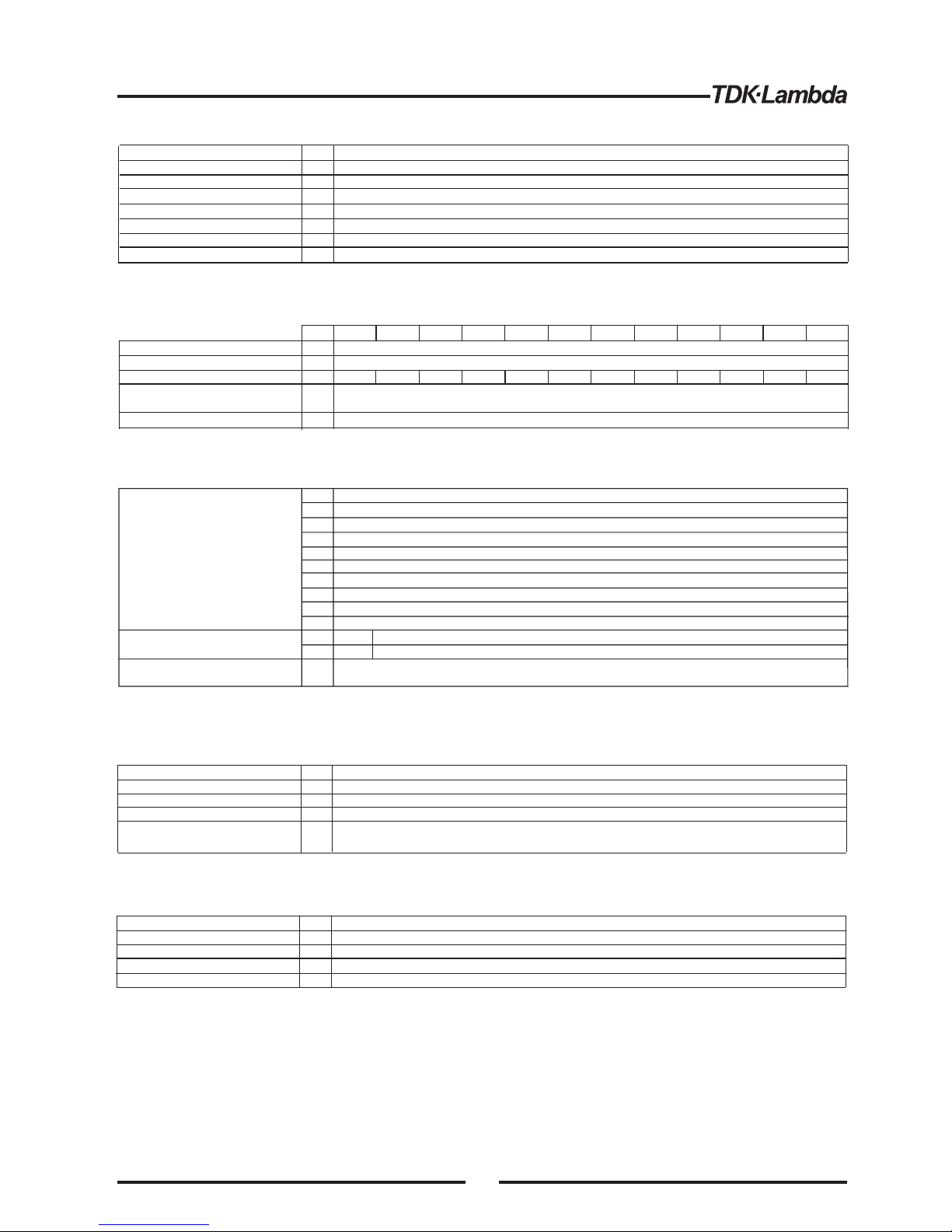
2.6.1 PROGRAMMING AND READBACK (RS232/485, Optional LAN/IEEE Interface)
1.Vout programming accuracy
2.Iout programming accuracy (*13)
3.Vout programming resolution
4.Iout programming resolution
5.Vout readback accuracy
6.Iout readback accuracy (*13)
7.Vout readback resolution
8.Iout readback resolution
---
---
---
---
---
---
---
---
0.05% of actual output voltage + 0.05% of rated output voltage
0.1% of actual output current +0.2% of rated output current
0.012% of full scale
0.012% of full scale
0.1% + 0.1% of rated output voltage
0.1% + 0.3% of rated output current
0.012% of full scale
0.012% of full scale
2.7 PROTECTIVE FUNCTIONS
1.Foldback protection
2.Over-voltage protection (OVP)
3.Over-voltage trip point
4.Output under voltage limit (UVL)
5.Over temperature protection
V
8
16
2010
30
40
60
80
100
150
300
600
---
---
---
---
V
Output shut-down when power supply change from CV to CC User presetable.
Inverter shut-down, manual reset by AC input recycle or by OUT button or by communication port command.
Preset by front panel or communication port. Prevents from adjusting Vout below limit. Does not affect analog
programming.
User selectable, latched or non latched.
0.5~10 0.5~12
2~36
1~24
1~19
2~44
5~66
5~165
5~110
5~88
5~330
5~660
2.8 FRONT PANEL
---
---
---
---
---
---
---
---
---
---
---
---
---
Vout/Iout manual adjust by separate encoders (coarse and fine adjustment).
OVP/UVL manual adjust by Vout. Adjust encoder.
Address selection by Voltage Adjust encoder. No of addresses:31.
Go to local control.
Output on/off
AC on/off
Front panel Lock
Foldback control
Baud rate selection: 1200, 2400, 4800, 9600 and 19200.
Re-start modes (automatic restart, safe mode).
Vout: 4 digits, accuracy: 0.5% of rated output voltage +/-1count.
Iout: 4 digits, accuracy: 0.5% of rated output current +/-1count.
VOLTAGE, CURRENT, ALARM, FINE, PREVIEW, FOLDBACK, REMOTE(RS232,RS485,IEEE), OUTPUT ON,
FRONT PANEL LOCK.
1.Control functions
2.Display
3.Indications
2.9 ENVIRONMENTAL CONDITIONS
1.Operating temperature
2.Storage temperature
3.Operating humidity
4.Storage humidity
5.Altitude
---
--%
%
---
0~50 C, 100% load.
-20~85 C
20~90% RH (no condensation).
10~95% RH (no condensation).
Maximum 3000m(10000ft). Derate output current by 2%/100m above 2000m.
Alternatively maximum ambient temp.derated by 1 C/100m above 2000m.
o
o
O
2.10 MECHANICAL
1.Cooling
2.Weight
3.Dimensions (WxHxD)
4.Vibration
5.Shock
---
Kg
mm
---
---
Forced air cooling by internal fans.
Less than 10Kg.
W: 422.8, H: 43.6, D: 441 (Refer to Outline drawing).
MIL-810F, method 514.5
Less than 20G, half sine, 11mS. Unit is unpacked.
11
Page 20
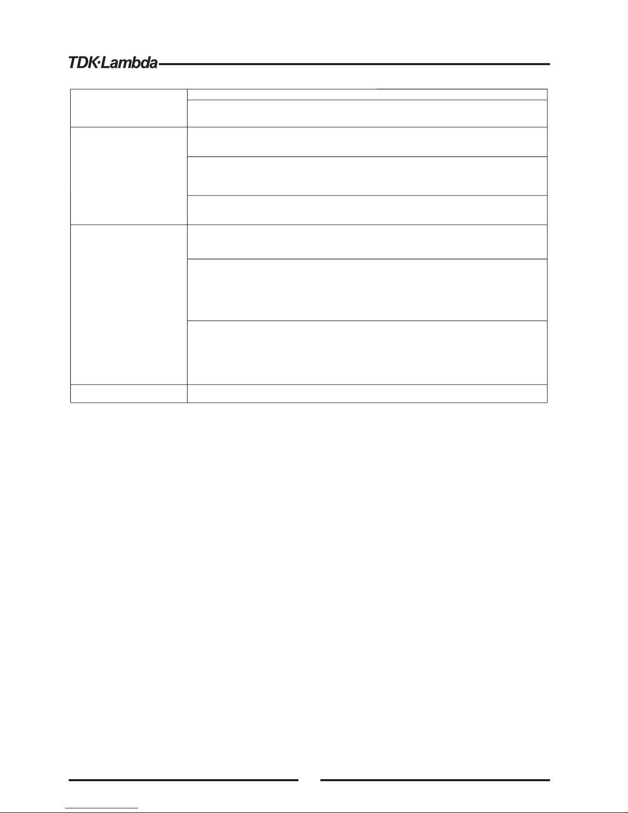
*1: Minimum voltage is guaranteed to maximum 0.2% of the rated output voltage.
*2: Minimum current is guaranteed to maximum 0.4% of the rated output current.
*3: For cases where conformance to various safety standards (UL, IEC etc.) is required, to be
described as 190~240Vac (50/60Hz).
*4: A ith rated output power.
*5: Not including EMI filter inrush current, less than 0.2mSec.
*6: At 170~265Vac, constant load.
*7: From No-load to Full-load, constant input voltage. Measured at the sensing point in Remote
Sense.
*8: For 8V~300V models: measured with JEITA RC-9131A (1:1) probe.
For 600V model: measured with 10:1probe.
*9: From10% to 90% or 90% to 10% of rated output voltage, with rated , resistive load.
*10: From 90% to 10% of rated output voltage.
*11: For load voltage change, equal to the unit voltage rating, constant input voltage.
*12: For 8V~16V models the ripple is measured at 2V rated output voltage and rated output
current. For other models, the ripple is measured at 10~100% of rated output voltage and
rated output current.
*13: The Constant Current programming readback and monitoring accuracy does not include the
warm-up and Load regulation thermal drift.
The supplemental characteristics give typical but non-warranted performance characteristics. The supplemental
characteristics are useful in assessing applications for the power supply. Several kinds of supplemental characteristics are
listed below.
1.Evaluation Data: Typical performance of the power supply.
2.Reliability Data: Reliability performance of the power supply.
3.EN61000 Data: Performance of the power supply under EN61000 test conditions.
4.EMI Data: Typical EMI (conducted and radiated) performance of the power supply.
The supplemental characteristics data is held in each Lambda sales and service facility. For further details please contact the
Lambda office nearest you.
NOTES:
2.12 SUPPLEMENTAL CHARACTERISTICS
t 200Vac input voltage, w
EN55022, EN55024, EN61000-3-3, FCC part 15, VCCI.
Conducted emmision - EN55022 class A, FCC part 15 class A, VCCI class A.
Radiated emmision - EN55022 class A, FCC part 15 class A, VCCI class A.
Models with Vout 50V: Output is SELV, all communication/control interfaces: RS232/485,
IEEE,
Isolated Analog,LAN, Sense, Remote Programming and Monitoring, 5V d.c. auxiliary output are
SELV.
Models with 60V≤Vout≤400V: Output is Hazardous, communication/control interfaces:
RS232/485, IEEE,Isolated Analog, LAN, Remote Programing and Monitoring (pins 1-3, pins14-
16), 5V d.c. auxiliary output are SELV, Sense, Remote Programming and Monitoring (pins 813, pins 21-25),15V auxiliary output are Hazardous.
Models with 400V Vout 600V: Output is Hazardous, all communication/control interfacesRS232/485, IEEE, Isolated Analog, LAN, Sense, Remote Programming and Monitoring (all
pins), 5V d.c./15V d.c. auxiliary outputs are Hazardous.
≤
≤<
2.11 SAFETY/EMC
2.Interface classification
4.Insulation resistance
More than 100Mohm at 25 C, 70%RH.
O
Vout 50V models:
Input-Output/communication/control/auxiliary outputs (SELV): 4242VDC 1min,
Input-Ground: 2828VDC 1min., Output/communication/control/auxiliary outputs (SELV)-Ground:
1000VDC 1min.
60V≤Vout≤100V models:
Input-Output/15V d.c. auxiliary output/communication/control (Hazardous): 2600VDC 1min,
Input-communication/control/5V d.c. auxiliary output (SELV): 4242VDC 1min,
Output/15V d.c. auxiliary output/communication/control (Hazardous): communication/control/5V d.c. auxiliary output (SELV): 1900VDC 1min,
Output/15V d.c. auxiliary output/communication/control (Hazardous): -Ground: 1200VDC 1min,
Input-Ground: 2828VDC 1min.
100V Vout 600V models:
Input-Output/15V d.c. auxiliary output/communication/control (Hazardous): 4000VDC 1min,
Input-communication/control/5V d.c. auxiliary output (SELV): 4242VDC 1min,
Output/15V d.c. auxiliary output/communication/control (Hazardous): -communication/control/
5V d.c. auxiliary output (SELV): 3550VDC 1min,
Output/15V d.c. auxiliary output/communication/control (Hazardous): -Ground: 2670VDC 1min,
Input-Ground: 2828VDC 1min.
≤
≤<
3.Withstand voltage
1.Applicable standards:
EMC
Safety
*14 Measure with JEITA RC-9131A(1:1) probe.
UL 60950-1:2007(Ed.2), IEC 60950-1:2005(Ed.2), EN 60950-1:2006(Ed.2)+A11:2009
12
Page 21
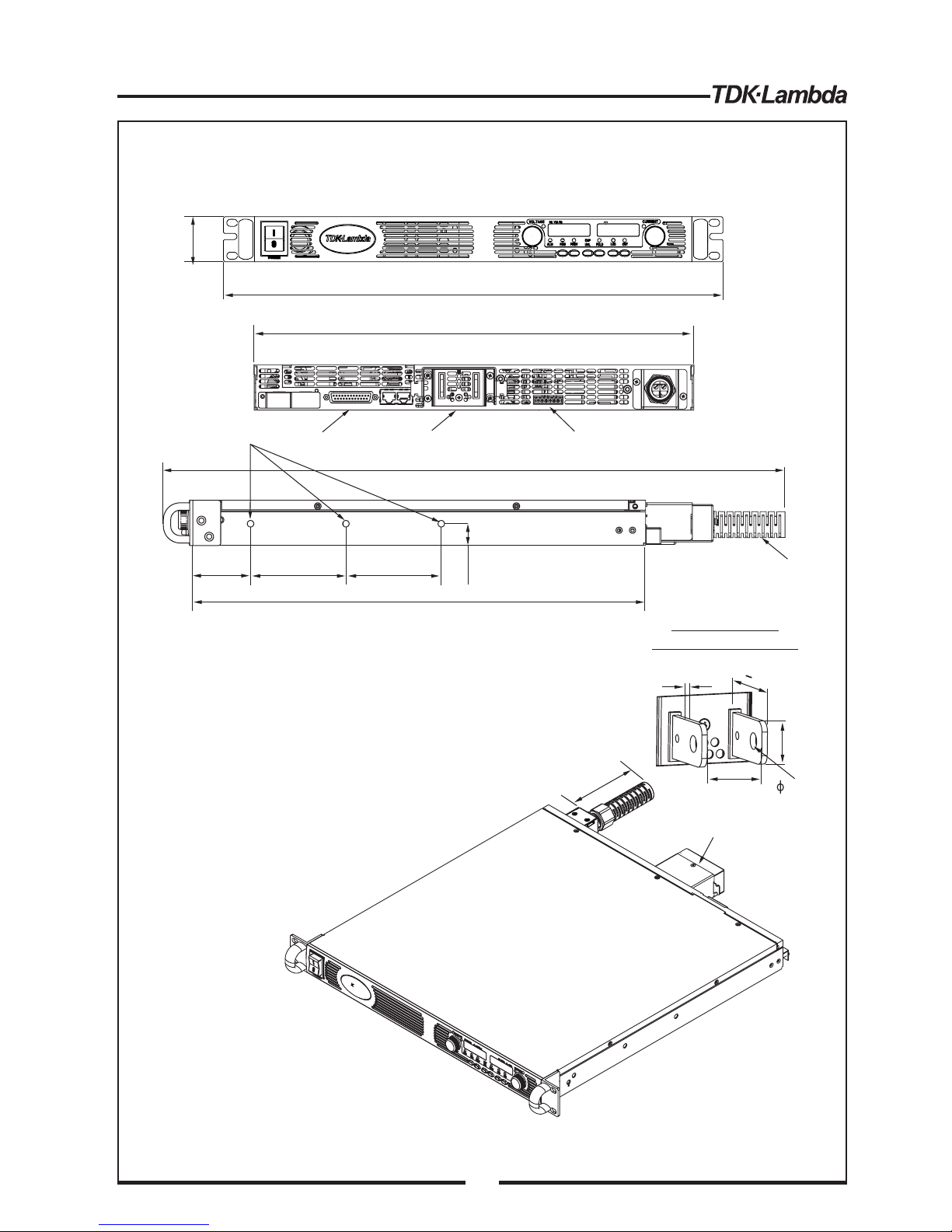
2.13 GENESYS 2400W POWER SUPPLIES
OUTLINE DRAWINGS
TM
482.8+/-1.0mm
43.6+/-0.3mm
A
A A
603.0+/-1.0mm
57.8+/-0.5
92.0+/-0.5
92.0+/-0.5
21.0
440.8+/-1.0mm
422.8+/-1.0mm
Note 1
Note 1
Note 4
Note 2 (150V~600V)
Note 2
Note 5
NOTES:
1.Mating plug supplied with power supply.
2.Bus-bars for 8V to 100V models. See detail.
Wire clamp connector for 150V to 600V models (shown).
3. AC cable strain relief (supplied with power supply).
4. Chassis slides: GENERAL DEVICES P/N: CC3001-00-S160
or equivalent, mounting holes #10-32 marked "A".
5. Bus Bars enclosure for 60V to 600V.
104+/-2.0mm
Note 3
39.5+0.5mm
22.0mm
3.0mm
30.0mm
Bus-Bar Detail
8V to 100V Models
8.5mm
T
D
L
a
m
b
d
a
-
I
T
D
L
amb
d
a
-
I
0-8V 0-300A
GEN8-300
13
Page 22
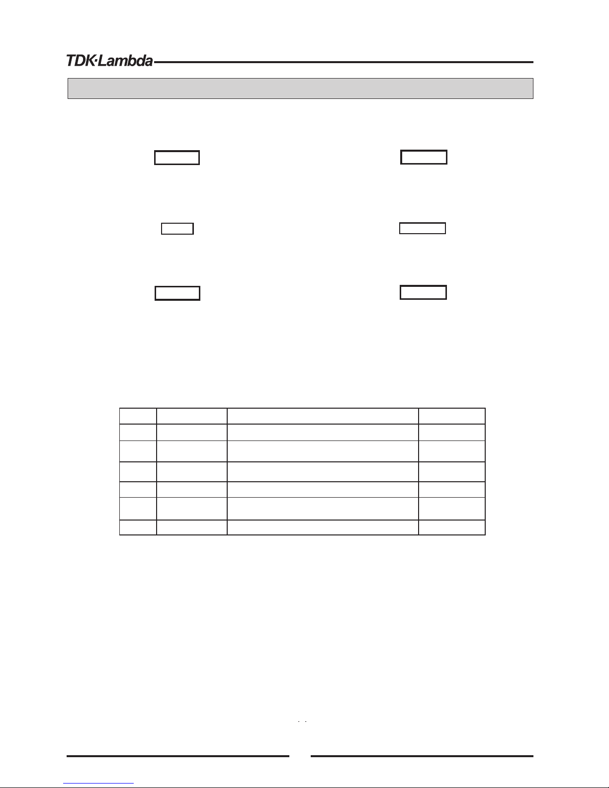
CHAPTER 3 INSTALLATION
3.1 GENERAL
3.2 PREPARATION FOR USE
3.3 INITIAL INSPECTION
3.4 RACK MOUNTING
This chapter contains instructions for initial inspection, preparation for use and repackaging for
shipment. Connection to PC, setting the communication port and linking Genesys power supplies
are described in Chapter 7.
.
n order to be operational the power supply must be connected to an appropriate AC source. The
AC source voltage should be within the power supply specification. Do not apply power before
reading, Section 3.6 and 3.7.
Table 3-1 below, describes the basic setup procedure. Follow the instructions in Table 3-1 in the
sequence given to prepare the power supply for use.
Prior to shipment this power supply was inspected and found free of mechanical or electrical
defects. Upon unpacking of the power supply, inspect for any damage which may have occured in
transit.
The inspection should confirm that there is no exterior damage to the power supply such as broken
knobs or connectors and that the front panel and meters face are not scratched or cracked. Keep all
packing material until the inspection has been completed. If damage is detected, file a claim with
carrier immediately and notify the Lambda sales or service facility nearest you.
The Genesys power supply series is designedto fit in a standard 19” equipment rack.
1. Use the front panel rack-mount bracketsto installthe power supply in the rack.
2. Use a support bar to provide adequate support for the rear of the power supply.Do not obstruct
the air exhaust at the rear panel of the unit.
TM
TM
I
3.4.1 Toinstall the Power Supply in a rack:
NOTE
HINWEIS
WARNING
WARNUNG
WARNUNG
WARNING
To avoid electric shock hazard, do not insert conductive
parts through the front panel slits.
Um die Gefahr eines elektrischen Schlags zu vermeiden,
stecken Sie keinerlei elektrisch leitenden Teile durch die
Schlitze der Frontabdeckung.
Genesys power supplies generate magnetic fields
which might affect the operation of other instruments. If
your equipment is susceptible to magnetic fiels, do not
position it adjacent to the power supply.
TM
Genesys -Stromversorgungen erzeugen magnetische
Felder, die den Betrieb anderer Ger te beeintr chtigen
k nnen. Falls Ihre Ausr stung empfindlich gegen
magnetische Felder ist, stellen Sie nicht in unmittelbarer
Nachbarschaft zur Stromversorgung auf.
TM
The Genesys series is intended only for installation in
Restricted Access Location (RAL). Access to Hazardous
parts (rear side of the power supply) shall be prevented
after installation.
TM
Die Genesys ist ausschlie lich f r die Installation in
zugangsbeschr nkten Bereichen (Restricted Access
Location, RAL) gedacht. Der Zugang zu gef hrlichen
Teilen (R ckseite des Ger ts) nach der Installation ist zu
unterbinden.
TM
1
2
3
4
5
6
Inspection
Installation
AC source
Test
Load connection
Default setting
Initial physical inspection of the power supply
Section 3.3
Installing the power supply,
Ensuring adequate ventillation.
AC source requirements
Connecting the power supply to the AC source.
Turn-on checkout procedure.
The power supply setting at shipment.
Wire size selection. Local /Remote sensing.
Single or multiple loads.
Section 3.4
Section 3.5
Section 3.6
Section 3.7
Section 3.8
Section 3.9
Section 7.2.1
Step no.
Item Description Reference
Table 3-1: Basic setup procedure
14
Page 23
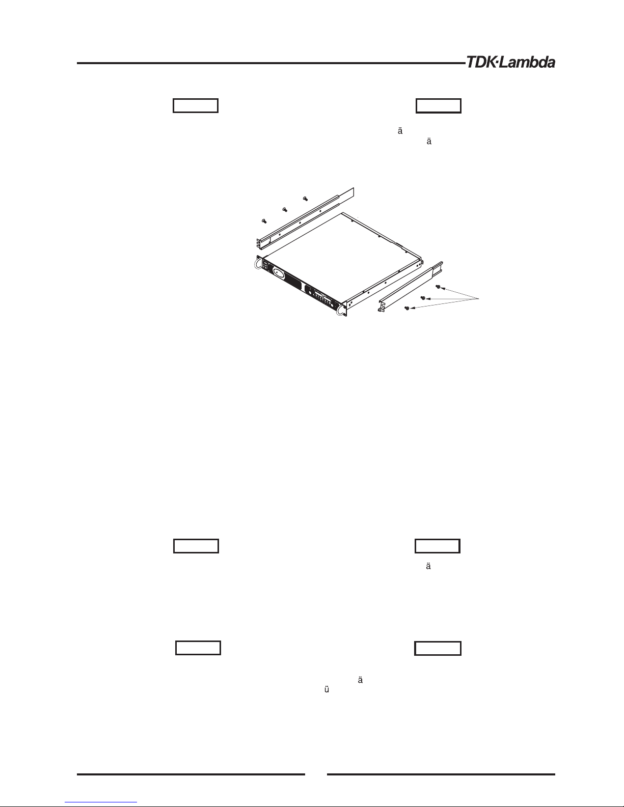
3.4.2 Rack Mount Slides (optional):
Use rack mount slides: General Devices P/N: CC3001-00-S160 (ordering P/N: C-300-S-116-RHLH) or equivalent to install the unit in a standard 19” equipment rack. Refer to Fig. 3-1 for slides
assembly instructions. Use three #10-32x0.38"(max.) screws at each side. To prevent internal
damage, use the specified screw length only.
This power supply is fan cooled. The air intake is at the front panel and the exhaust is at the rear
panel. Upon installation allow cooling air to reach the front panel ventilation inlets. Allow minimum
10cm (4 Inch) of unrestricted air spaceat the front and the rear of the unit.
The power supply should be used in an area that the ambient temperature does not exceed +50 C.
The Genesys series designed for use in TN, TT and IT power distribution systems.Depending on
its input option, the Genesys 2400W series can be operated from a nominal 190V to 240V, single
and three phase, 47~63Hz. The input voltage range and current required for each model is specified
in Chapter 2. Ensure that under heavy load, theAC voltage supplied to the power supply does not fall
below the specifications described in Chapter 2.
3.5 LOCATION, MOUNTING AND COOLING
3.6 AC SOURCE REQUIREMENTS
3.7 AC INPUT POWER CONNECTION
o
TM
TM
Ensure that the screws used to attach the slides to the unit
do not penetrate more than 6mm into the sides of the unit.
Stellen Sie sicher, dass die Schrauben, mit denen die
Schienen am Ger t angebracht werden, nicht mehr als
6mm in die Seiten des Ger ts hineinragen.
Connection of this power supply to an AC power source
should be made by an electrician or other qualified
personnel.
Der Anschluss dieses Ger tes an ein AC-Versorgungsnetz
sollte durch einen Elektriker oder anderes entsprechend
qualifiziertes Personal erfolgen.
The power supply shall be connected to the AC source via protective device (circuit breaker,
fuses, ...etc.) rated 30A max.
Es besteht die Gefahr eines elektrischen Schlags, wenn
das Geh use des Netzteils (mitsamt Abdeckung) nicht
ber den PE-Leiter des Netzkabels mit einer Schutzerde
verbunden ist.
There is a potential shock hazard if the power supply
chassis (with cover in place) is not connected to an
electrical safety ground via the safety ground in the AC
input connector
Fig.3-1: Rack-mount slides assembly
T
D
L
a
mb
da
-
I
#10-32x0.38"(max.)
screws
CAUTION
CAUTION
VORSICHT
VORSICHT
WARNING
WARNUNG
15
Page 24
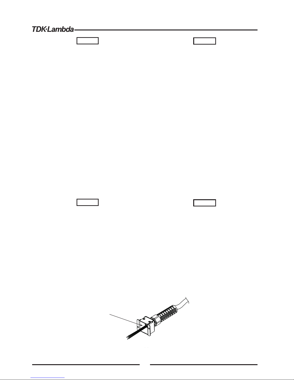
3.7.1 AC Input Connector
3.7.2 AC Input Cord
3.7.3 AC Input Wire Connection
1.Stripthe outsideinsulation oftheAC cable approx. 10cm.Trim the wires so that the ground wire is
10mm longer than the other wires. Strip 10mm at the end of each of the wires.
2.Unscrew the base of the strain relief from the helix-shaped body. Insert the base through the
outside opening in the AC input cover and screw the locknut securely (11-14 Lb-inch.) into the
base, from the inside.
3.Slide the helix-shaped body onto theAC cable. Insert the stripped wires through the strain relief
base until the outer cable jacket is flush with the edge of the base. Tighten(16-18 Lb-inch.) the
body to the base while holding the cable in place. Now the cable is securely fastened inside the
strain relief. Refer to Fig.3-2.
TheAC input connector is a 4-Terminal wire clamp located onthe rear panel.
Phoenix-Contact P/N: FRONT4-H-7.62/4. Use suitable wires and tightening torque as follows:
1. Wire diameter: 12AWG or 10AWG.
2. Tightening torque: 4.4-5.3Lb-inch. (0.5-0.6Nm).
AC input cord is not provided with power supply.
Das Netzteil wird ohne AC-Netzkabel ausgeliefert.
Refer to section 1.3.4 for details of the recommended AC
input cords and to section 3.7 for disconnected device
requirement.
In Abschnitt 1.3.4 finden Sie Empfehlungen f r die zu
verwendenden AC-Netzkabel, und Abschnitt 3.7 gibt
Hinweise zur vollst ndigen Trennung des Ger tes vom
Netz.
Some components inside the power supply are at AC
voltage even when the On/Off switch is in the “Off ”
position. To avoid electric shock hazard, disconnect the
line cord and load and wait two minutes before removing
cover.
Einige Komponenten innerhalb des Netzteils f hren
Netzspannung, selbst wenn der On/Off-Schalter in der
Position “Off” steht. Um die Gefahr eines elektrischen
Schlags zu vermeiden, trennen Sie es vom Netz und
warten Sie zwei Minuten, bevor Sie die Abdeckung
entfernen.
The power supply ON/OFF switch is not the main “disconnect device” and does not completely
disconnect all the circuits from the AC source.
An appropriately rated “disconnect device” such as circuit breaker,type B plug on power cord, ...etc.,
shall be provided in the final installation. The “disconnect device”
for one phase units shall
disconnect both supply lines simultaneously.The “disconnected device” mustl be easily accessible.
WARNING
WARNING
WARNUNG
WARNUNG
CAUTION
AC Input Wires No Conductor Pretreatment: Phoenix Contact clamping parts are designed so
that all kinds of copper conductors canbe clamped without pretreatment.
It is forbidden to solder the conductors. The solder tin yields and fractures under high pressure. The
result is increased contact resistance and an excessive temperature rise. In addition, corrosion
caused by pickling or fluxes has been observed on soldered conductor ends. Notch fractures at the
transition point from the rigid to the flexible conductor area are also possible.
Fig.3-2: Stripped Wires installed in Strain Relief
Screw-on
Locknut
16
Page 25
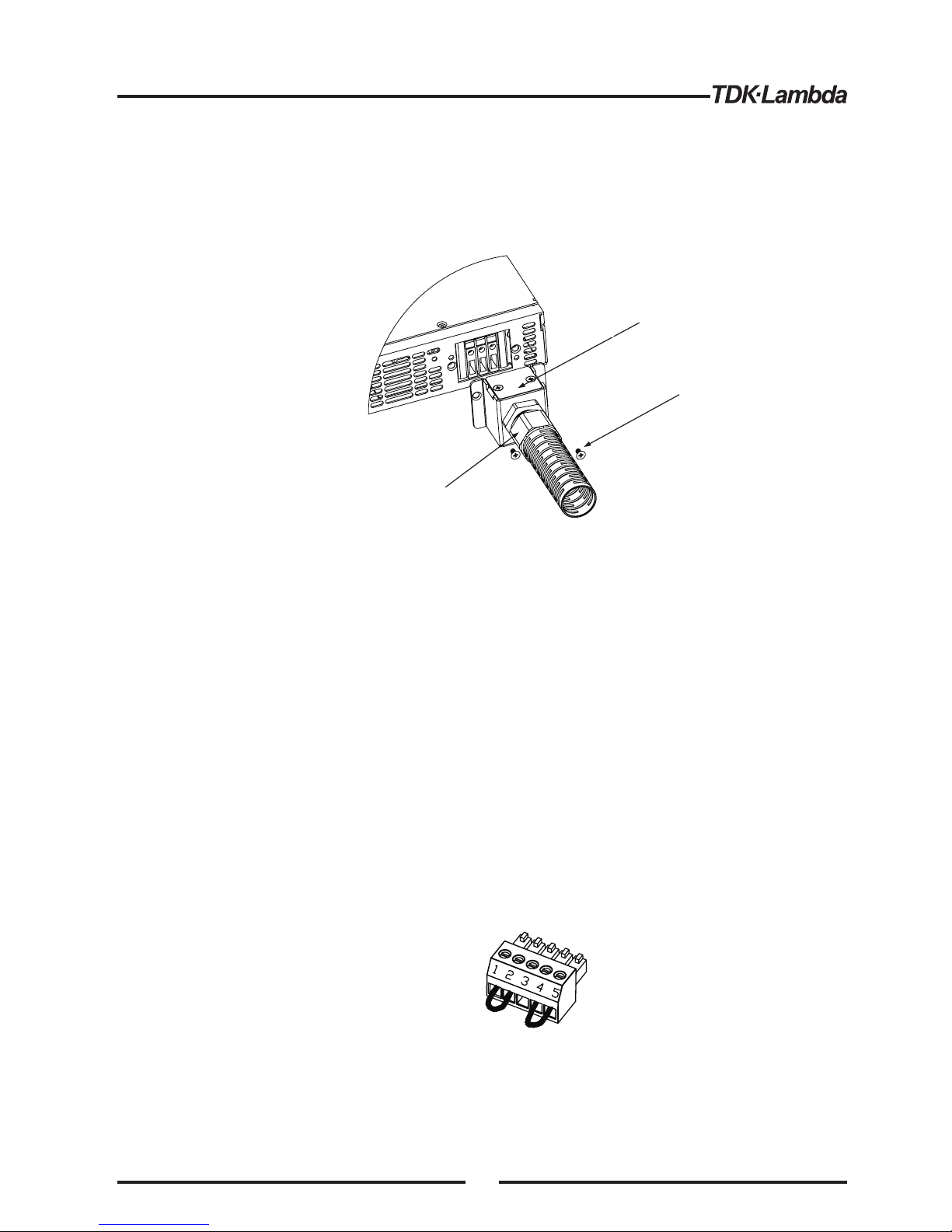
Fig.3-3: AC input cover and strain relief, 2400W models
4.Route the AC wires to the input connector terminals as required. To connect the wires, loosen
the terminal screw, insert the stripped wire into the terminal and tighten the screw securely
(4.4-5.3 Lb-inch.).
5.Route the wires inside the cover to prevent pinching. Fasten the cover to the unit using the
M3x8 Flat Head screws are provided. Strain relief cover could be opened for inspection.
Refer to Fig.3-3 for details.
3.8 TURN-ON CHECKOUT PROCEDURE
3.8.1 General
3.8.2 Prior to Operation
The following procedure ensures that the power supply is operational and may be used as a basic
incoming inspection check. Refer to Fig.4-1 and Fig.4-2 for the location of the controls indicated in
the procedure.
1. Ensure that the power supply isconfigured to the default setting:
-AC On/Off switch at Off position.
-Dip switch : All positions at Down (”Off”) position.
-Sense connector : Configured to Local Sense as shown in Fig.3-4:
1 Remote (+) sense
2 Local (+) sense
3 Not connected
4 Local (-) sense
5 Remote (-) sense
-For units equipped with IEEE option, ensure that the IEEE_En switch is in Up (default) position
(Refer to Fig.4-2, item 8 for location), if checkout is to be done in IEEE mode.
Fig.3-4: Sense connector default connection
Plug P/N: MC 1.5/5-ST-3.81
(Phoenix)
Removable cover.
Remove only to inspect AC input
wires connections. Re-instal cover
after inspection.
Assembled Strain Relief
M3x8
Flat Head screws
(2 places)
17
Page 26

2. Connect the unit to an AC source as described insection 3.7.
3. Connect a DVM with appropriate cablesfor the rated voltage to the output terminals.
4. Turn the frontpanelAC power switch to On.
1. Turnon the output by pressing OUT pushbutton so the OUTLED illuminates.
2. Observe the power supply VOLTdisplay and rotate the Voltage encoder. Ensure that the
output voltage varies while the VOLTencoder is rotated. The minimum control range is from
zero to the maximum rated output for the power supply model.
Compare the DVM reading with the front panel VOLT display to verify the accuracy of the
VOLT display.Ensure thatthe front panel VOLT LED is on.
3. Turnoff the front panelAC power switch.
1. Ensure that the front panel AC power switch is at Offposition and the DVM connected to the
output terminals shows zero voltage.
2. Connect a DC shunt across theoutput terminals. Ensure that the shunt andthe wires' current
ratings are higher than the power supply rating. Connect a DVM to the shunt.
3. Turn the frontpanelAC power switch to On position.
4. Turn on theoutput by pressing OUT pushbutton so the OUTLED illuminates.
5. Observe the power supply CURRENT display and rotatethe CURRENTencoder. Ensure that
the output current varies while the CURRENT encoder is rotated. The minimum control range
is from zero to the maximum rated output for the power supply model.
Compare the DVM reading with the front panel CURRENT display to verify the accuracy of
the CURRENT display. Ensure thatthe front panel CURRENT LED is on.
6. Turn off the frontpanelAC power switch.
7. Remove the shunt from the powersupply output terminals.
Refer to Section 5.3 for explanation ofthe OVP function prior to performing the procedure below.
1. Turn the frontpanelAC power switch to On position and turn on the output by pressing OUT
pushbutton.
2. Using the VOLTencoder, adjust the output voltage to approx. 10% of the unit voltage rating.
3. Momentarily press
the OVP/UVL button so that the CURRENT display shows “OUP”.The
VOLTAGEdisplay will show the last setting of the OVPlevel.
4. Rotate the VOLT encoder CCW to adjust the OVP setting to 50% of the unit voltage rating.
5. Waita few seconds until the VOLT display returns to showthe output voltage.
6. Adjust the output voltage toward it’s maximum and check that the outputvoltagecannot be
increased more than the OVP setting.
7. Adjust OVP limit tothe maximum by repeating step 3 androtatingthe VOLT encoder CW.
Refer to Section 5.4 for explanation ofthe UVLfunction priorto performing the procedure below.
1. Press the OVP/UVL button TWICE so that the CURRENT display shows "UUL".The VOLTAGE
display will show the last setting of the UVL level.
2. Rotate the VOLT encoder to adjust the UVLlevel to approx. 10% of the unit voltage rating.
3. Waita few seconds until the VOLTdisplay returns to show the output voltage.
4. Adjust the output voltage toward it’s minimum and check that the outputvoltagecannot be
decreased below the UVL setting.
5. Adjust the UVLlimit to the minimum by repeating step1 and rotating the VOLTencoder CCW.
3.8.3 Constant Voltage Check
3.8.4 Constant Current Check
3.8.5 OVP Check
3.8.6 UVL Check
18
Page 27

Refer to Section 5.5 for explanation of the FOLD function prior to performing the procedure
below.
1. Ensure that the output voltage is set to approx. 10% of the unit rating.
2. Adjust the CURRENT encoder to set the current limit to approx. 10% of the unit rating.
3. Momentarily press the FOLD button. Ensure that the FOLD LED illuminates. The output
voltage remains unchanged.
4. Short the output terminals momentarily (approx. 0.5 sec.). Ensure that the output voltage falls
to zero, the VOLT display shows “Fb” and the ALARM LED blinks.
5. Press the FOLD button again to cancel the protection. The output voltage remains zero.
6. Press OUT button. Ensure that the output voltage returns to it’s last setting.
7. Turn the output off by pressing OUT button. Ensure that the VOLT display shows “OFF”.
1. Press and hold the REM/LOC button for approx. 3sec. The VOLT display will show the
communication port address.
2. Using the VOLT adjust encoder, check that the address can be set within the range of 0 to 30.
1. Press and hold the REM/LOC button for approx. 3sec. The CURRENT display will show the
communication port Baud Rate.
2. Using The CURRENT adjust encoder, check that the Baud Rate can be set to 1200, 2400,
4800, 9600 and 19200.
3.8.8 Address Setting
3.8.9 Baud Rate Setting
3.9 CONNECTING THE LOAD
Shorting the output may expose the user to hazardous
voltages. Observe proper safety procedures.
Turn off the AC input power before making or changing any
rear panel connection. Ensure that all connections are
securely tightened before applying power. There is a
potential shock hazard when using a power supply with a
rated output greater than 40V.
3.9.1 Load Wiring
3.9.2 Current Carrying Capacity
at least
The following considerations should be made to select wiring for connecting the load to the power
supply:
* Current carrying capacity of the wire (refer to 3.9.2)
* Insulation rating of the wire should be at least equivalent to the maximum output voltage of
the power supply.
* Maximum wire length and voltagedrop (refer to 3.9.2)
* Noise and impedance effects of the load wiring (refer to 3.9.4).
Twofactors must be considered when selecting the wire size:
1. Wires should be heavyenough not to overheat while carrying the power supply load
current at the rated load, or the current that would flow in the event the load wires were
shorted, whichever is greater.
3.8.7 Foldback Check
WARNING
WARNING
WARNUNG
WARNUNG
Schalten Sie die Netzversorgung aus, bevor Sie
Verbindungen an der Rückseite des Gerätes vornehmen
oder ändern. Stellen Sie sicher, dass alle Verbindungen fest
und sicher sitzen, bevor Sie das Netz einschalten.
Bei Stromversorgungen mit einer Nennausgangsspannung
von mehr als 40V besteht grundsätzlich die Gefahr eines
elektrischen Schlags.
Das Kurzschlie en des Ausgangs kann den Anwender
einer gef hrlichen Spannung aussetzen. Beachten Sie
die entsprechenden Sicherheitsrichtlinien.
ß
ä
19
Page 28
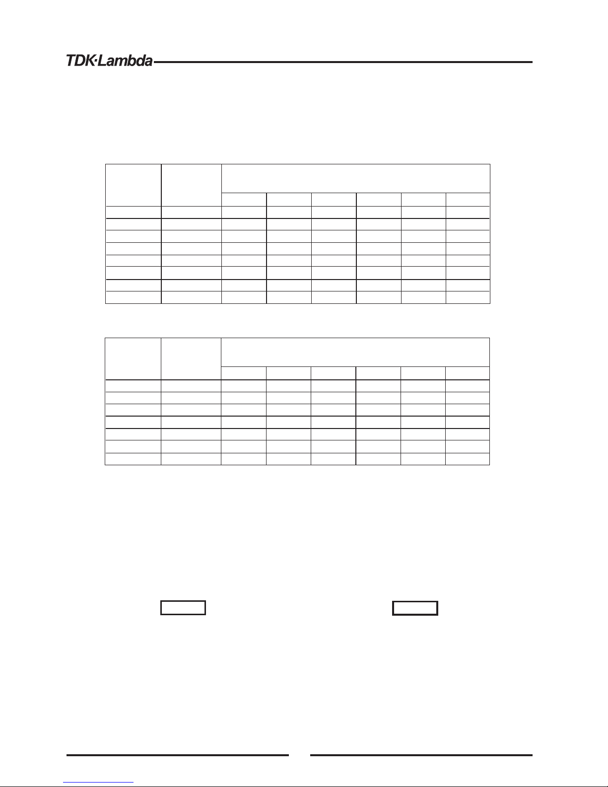
When local sensing, a short from +LS or +S to -V or -S or LS, will cause damage to the power supply. Reversing the
sense wires might cause damage to the power supply in
local and remote sensing. (Do not connect -S to +V or +S to
-V.)
Table 3-2: Maximum wire length for 1V drop on lead (in feet)
Table 3-3: Maximum wire length for 1V drop on lead (in meters)
2. Wire size should be selected toenable voltage drop per lead to be lessthan 1.0V at the rated
current. Although units will compensate for up to 5V in each load wire, it is recommended to
minimize the voltage drop (1V typical maximum) to prevent excessive output power consumption from the power supply and poor dynamic response to load changes. Please refer to
Tables 3-2 and 3-3 for maximumwire length to limit voltage drop in American and European
dimensions respectively.
Wire size
AWG
14
12
10
8
6
4
2
0
2.526
1.589
0.9994
0.6285
0.3953
0.2486
0.1564
0.0983
10A
40
60
100
160
250
400
600
1000
20A
20
30
50
80
125
200
300
500
50A
8
12
20
32
50
80
125
200
100A
4
6
10
15
25
40
60
100
200A
2
3
5
8
12
20
30
50
400A
---
--2
4
6
10
15
25
Resistivity
Ohm/1000ft
Maximum length in Feet to limit
voltage drop to 1V or less
Cross sect.
area
(mm )
2
2.5
4
6
10
16
25
35
8.21
5.09
3.39
1.95
1.24
0.795
0.565
400A
0.3
0.5
0.7
1.25
2
3.1
4.4
10A
12.0
18.6
29.4
51.2
80.0
125.0
177.0
20A
6.0
9.8
14.8
25.6
40.0
62.0
88.0
50A
2.4
4.0
5.8
10.2
16.0
25.2
35.4
200A
0.6
1.0
1.45
2.5
4
6.3
8.8
100A
1.2
2
2.9
5.1
8
12.6
17.7
Resistivity
Ohm/Km
Maximum length in meters to limit
voltage drop to 1V or less
For currents not shown in Table 3-2 and 3-3, use the formula:
Maximum length=1000/(current x resistivity)
where current is expressed in Amperes and resistivity in ohms/km or ohms/1000ft.
3.9.3 Wire termination
The wires should be properly terminated with terminals securely attached. DO NOT use unterminated wires for load connection at the power supply.
CAUTION
VORSICHT
Vermeiden Sie bei lokalem Sensing unbedingt einen
Kurzschluss zwischen -V und +LS oder +S sowie
zwischen -LS und -V oder -S. Ein solcher Kurzschluss
würde das Netzteil beschädigen. Ein Vertauschen der
Sense-Leitungen kann das Netzteil bei lokalem wie bei
Remote-Sensing beschädigen. (Verbinden Sie daher
nicht -S mit +V oder +S mit -V).
20
Page 29
3.9.4 Noise and Impedance Effects
3.9.5 Inductive loads
3.9.6 Making the load connections
To minimize the noise pickup or radiation, the load wires and remote sense wires should be twistedpairs to the shortest possible length. Shielding of sense leads may be necessary in high noise
environments. Where shielding is used, connect the shield to the chassis via a rear panel Ground
screw. Even if noise is not a concern, the load and remote sense wires should be twisted-pairs to
reduce coupling, which might impact the stability of power supply. The sense leads should be
separated from the power leads.
Twisting the load wires reduces the parasitic inductance of the cable which could produce high
frequency voltage spikes at the load and the output of power supply, because of current variation in
the load itself.
The impedance introduced between the power supply output and the load could make the ripple
and noise at the load worse than the noise at the power supply rear panel output.Additional filtering
with bypass capacitors at the load terminals may be required to bypass the high frequency load
current.
Inductive loads can produce voltage spikes that may be harmful to the power supply. Adiode should
be connected across the output. The diode voltage and current rating should be greater than the
power supply maximum output voltage and current rating. Connect the cathode to the positive
output and the anode to the negative output of the power supply.
Where positive load transients such as back EMF from a motor may occur, connect a surge
suppressor across the output to protect the power supply. The breakdown voltage rating of the
suppressor must be approximately 10% higher than the maximum output voltage of the power
supply.
Ensure that the load wiring mounting hardware does
not short the output terminals. Heavy connecting
cables must have some form of strain relief to prevent
loosening the connections or bending the bus-bars.
8V to 100V Models
Refer to Fig.3-6 for connection of the load wires to the power supply bus-bars and to Fig.3-7
for mounting the bus-bars enclosure to the chassis.
Hazardous voltages may exist at the outputs and the
load connections when using a power supply with a
rated output greater than 40V. To protect personnel
against accidental contact with hazardous voltages,
ensure that the load and its connections have no
accessible live parts. Ensure that the load wiring
insulation rating is greater than or equal to the
maximum output voltage of the power supply.
WARNING
CAUTION
VORSICHT
WARNUNG
Bei Stromversorgungen mit einer
Nennausgangsspannung von mehr als 40V können
an den Ausgängen und den Verbindungen zur Last
gef hrliche Spannungen anliegen. Um den
Anwender vor einem versehentlichen Kontakt mit
gefährlichen Spannungen zu schützen, stellen Sie
sicher, dass die Last und ihre Verbindungen keine
ber hrbaren spannungsführenden Teile aufweisen.
Stellen Sie auch sicher, dass die Isolierung aller
Kabel mindestens für die maximal mögliche
Ausgangsspannung des Netzteils ausgelegt ist.
Stellen Sie sicher, dass über die Anschlussleitungen
zur Last kein Kurzschluss der Ausgangsklemmen
erfolgen kann. Schwere Anschlusskabel benötigen
eine Zugentlastung, um zu verhindern, dass sich
Verbindun gen lösen oder die Stromschinen
verbiegen.
21
Page 30
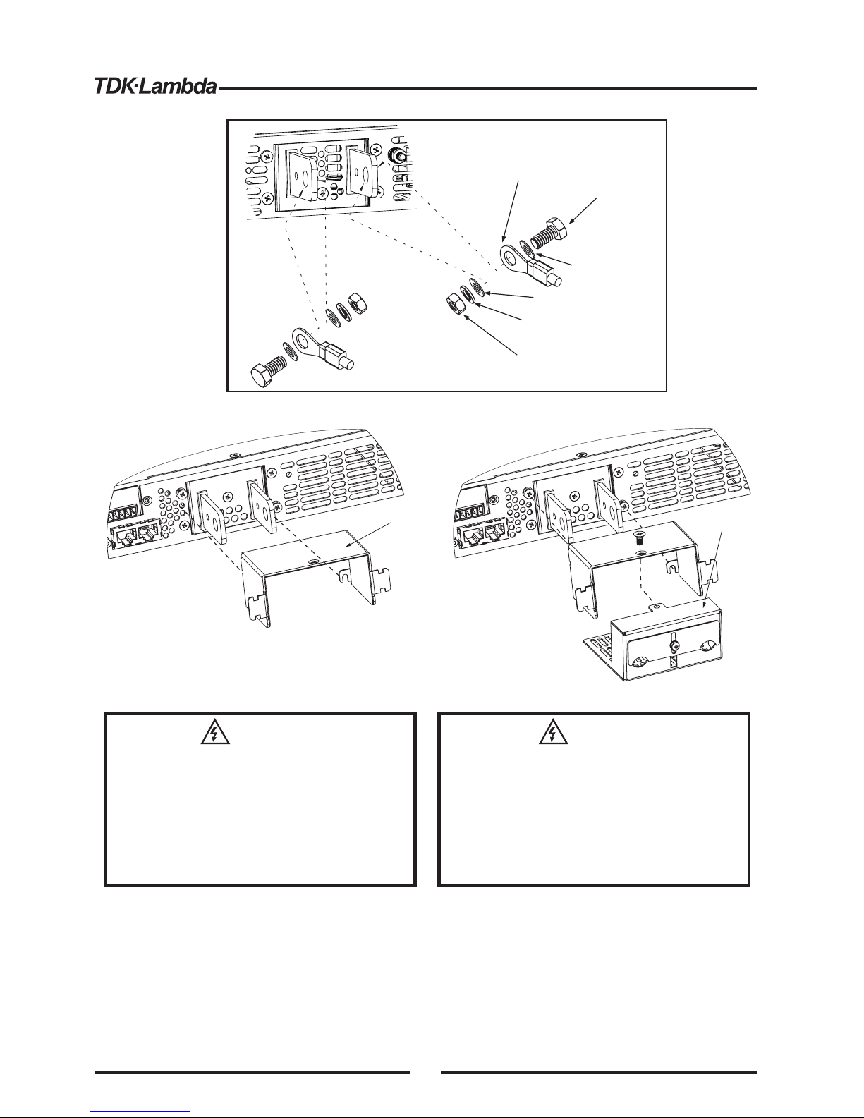
Hazardous voltages exist at the outputs and the load
connections. To protect personnel against accidental
contact with hazardous voltages, ensure that the load
and its connections have no accessible live parts.
Ensure that the load wiring insulation rating is greater
than or equal to the maximum output voltage of the
power supply.
Fig. 3-5: Load wires connection , 8V to 100V models.
150V to 600V Models
M8x15 screw (2 places)
Hex Nut (2 places)
Flat washer (2 places)
Spring washer (2 places)
Wire terminal lug (2 places)
Flat washer
(2 places)
Screws tightening torque: 104-118 Lb-inch.
WARNING
WARNUNG
An den AusgIängen und den Lastverbindungen liegen
gefährliche Spannungen an. Um dan Anwender vor
einem versehentlichen Kontakt mit gefährlichen
Spannungen zu schützen, stellen Sie sicher, dass die
Last und ihre Verbindungen keine berührbaren
spannungsführenden Teile aufweisen. Stellen Sie auch
sicher, dass die solierung aller Kabel mindestens für
die maxima l mögliche Ausgangsspannu ng des
Netzteils ausgelegt ist.
Output Load Wires No Conductor Pretreatment: Phoenix Contact clamping parts are designed
so that all kinds of copper conductors can be clamped without pretreatment.
It is forbidden to solder the conductors. The solder tin yields and fractures under high pressure. The
result is increased contact resistance and an excessive temperature rise. In addition, corrosion
caused by pickling or fluxes has been observed on soldered conductor ends. Notch fractures at the
transition point from the rigid to theflexible conductor area are also possible.
CAUTION
Fig. 3-6 Bus-bars
cover 8V to 40V
Fig. 3-7 Bus-bars
enclosure 60V~100V
Fix the bus-bars enclosure
top cover using the screws
marked “A”. Tighten the
screws after fixing.
Enclosure top cover
Enclosure
bottom cover
Fix the bus-bars enclosure top cover
using the screws marked “A”.
Loosen screw “B” to release the
shutter. Insert load wires through
enclosure bottom cover opening and
connect load wires to the bus bars.
Assemble the enclosure bottom
cover by using screw C. Tighten
screws “A”, “B” & “C” after fixing.
A
A
A
B
A
C
22
Page 31
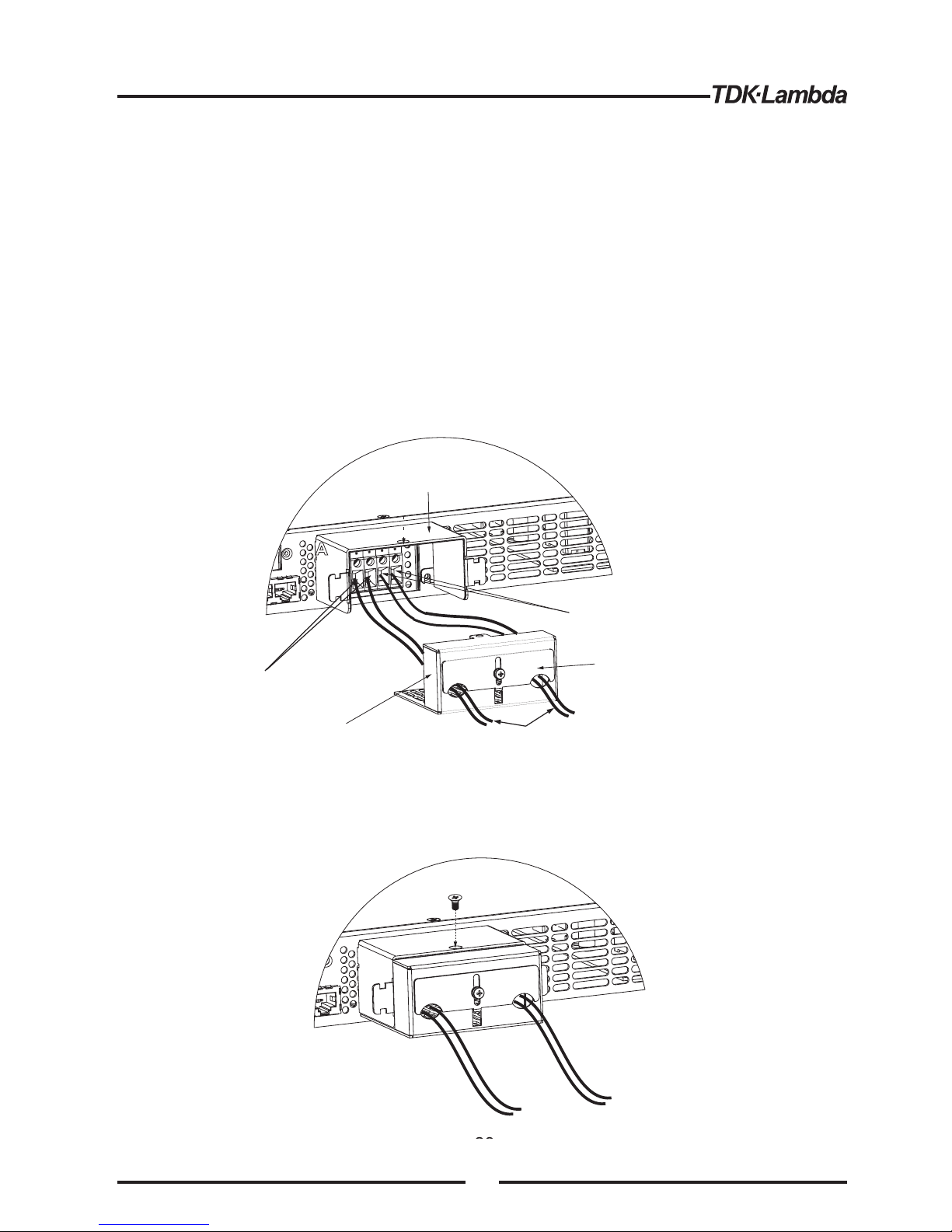
The 150V to 600V models have a four terminal wire clamp output connector:
Phoenix Contact P/N: FRONT4-H-7.62/4.
The two left terminals are the positive outputs and the other two right terminals are the negative
outputs. Max. 30A per terminal.
The connector requirements are as follows:
1. Wires: AWG18 to AWG10.
2. Tightening torque: 4.4-5.3Lb-inch. (0.5-0.6Nm).
Follow the below instructions for connection of the load wires to the power supply:
1. Strip approx.10mm at the end of each of the load wires.
2. Loosen the connector terminal screws.
3. Loosen screw “B” from enclosure bottom cover to release the shutter.
4. Insert stripped wires into enclosure bottom cover opening and then to the terminals,
tighten the terminals screws securely (see fig.3-8)
5. Loosen the two chassis screws marked “A” halfway.
6. Assemble the enclosure top cover to the chassis and tighten screws “A” (tightening torque:
4.8 - 5.3 Lb-inch).
7. Assemble the enclosure bottom cover to it’s place, as shown in Fig.3-9,using screw “C”,
(tightening torque 4.8-5.3 Lb-inch).
8. Slide down the shutter to secure load wires in place, and tighten screw “B”.
Fig.3-9: Enclosure assembly
B
Fig.3-8: Load wires connection to the output connector
Load wires
Negative (-)
Output/Return
Positive output (+)
Shutter
Enclosure bottom cover
Enclosure top cover
C
B
A
A
23
Page 32
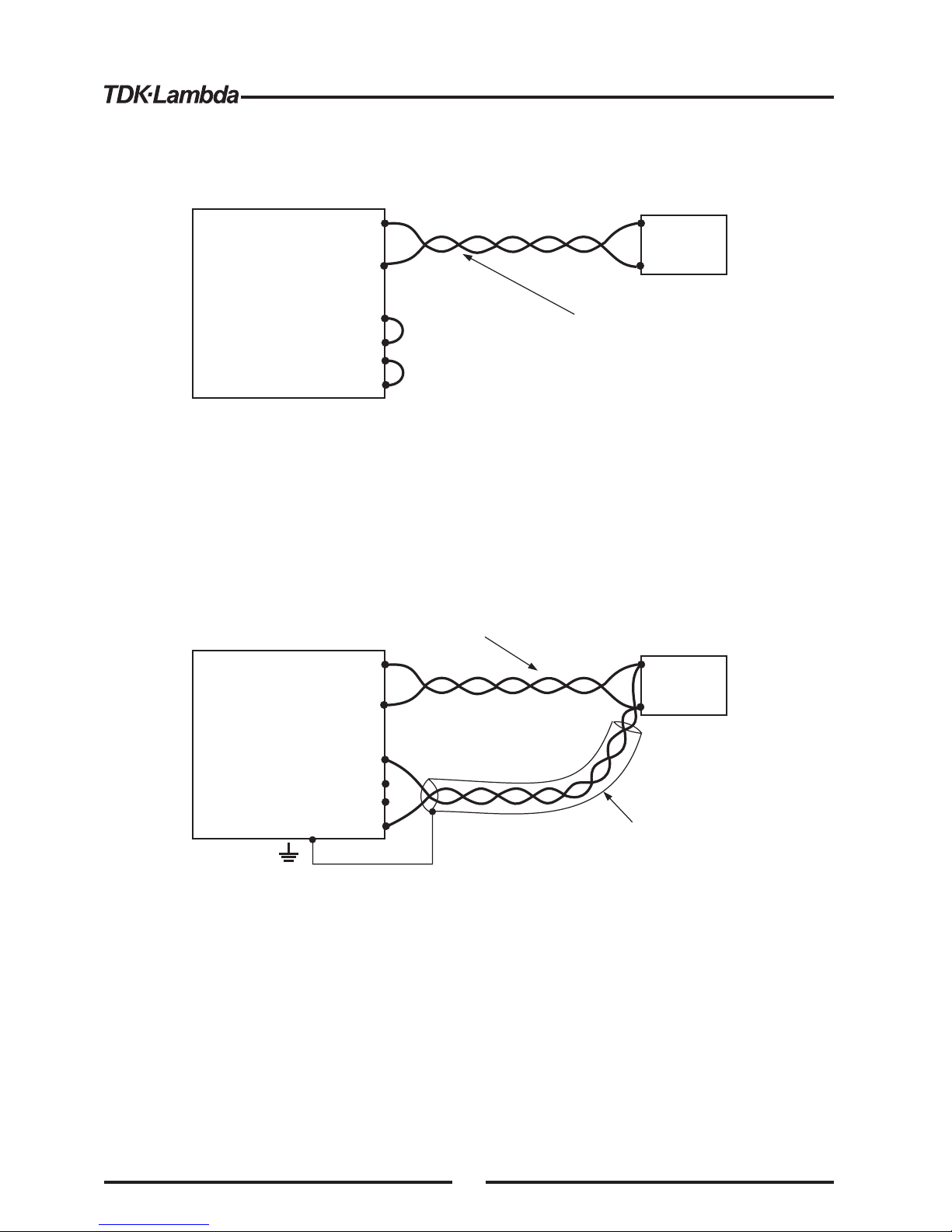
3.9.7 Connecting single loads, local sensing (default).
Fig.3-11 shows recommended load and sensing connections for a single load. The local sense lines
shown are default connections at the rear panel J2 sense connector. Local sensing is suitable for
applications where load regulation is less critical.
-
-
Rem.sense
Local sense
Local sense
Rem.sense
+
+
Load lines, twisted
pair, shortest length
possible.
+V
-V
Load
+
-
Power
Supply
Fig.3-11: Single load connection, local sensing
3.9.8 Connecting single loads, remote sensing
Fig.3-12 shows recommended remote sensing connection for single loads.
Remote sensing is used when, in Constant Voltage mode, the load regulation is important at the
load terminals. Use twisted or shielded wires to minimize noise pick-up. If shielded wires are used,
the shield should be connected to the ground at one point, either at the power supply chassis or the
load ground. The optimal point for the shield ground should be determined by experimentation.
-
-
Rem.sense
Local sense
Local sense
Rem.sense
+
+
Sense lines. Twisted
pair or shielded.
+V
-V
Load
+
-
Power
Supply
Load lines. Twisted pair
shortest length possible.
Fig.3-12: Remote sensing, single load
3.9.9 Connecting multiple loads, radial distribution method
Fig.3-13 shows multiple loads connected to one supply. Each load should be connected to the
power supply’s output terminals using separate pairs of wires. It is recommended that each pair of
wires will be as short as possible and twisted or shielded to minimize noise pick-up and radiation.
The sense wires should be connected to the power supply output terminals or to the load with the
most critical load regulation requirement.
24
Page 33
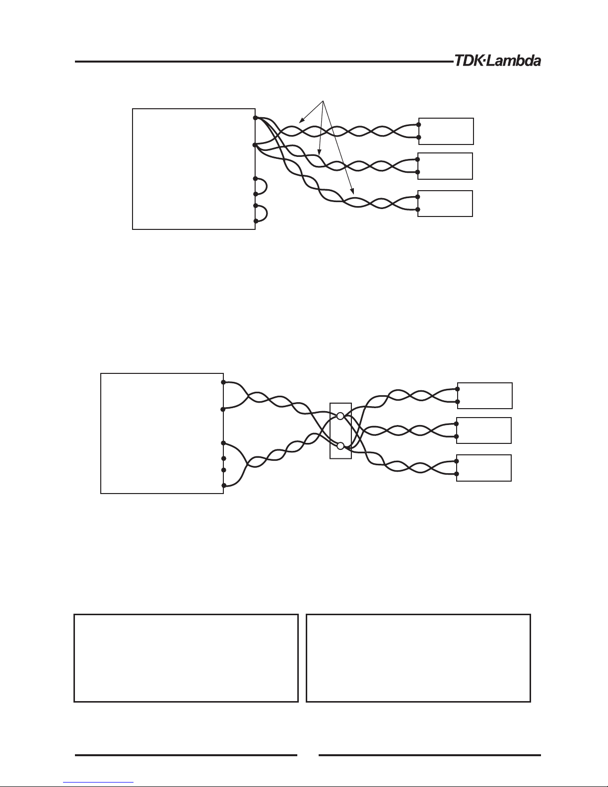
-
-
Rem.sense
Local sense
Local sense
Rem.sense
+
+
Load lines, twisted pair,
shortest length possible.
+V
-V
Load#1
+
-
Load#3
+
-
Load#2
+
-
Power
Supply
Fig.3-13: Multiple loads connection, radial distribution, local sense
-
-
Rem.sense
Local sense
Local sense
Rem.sense
+
+
Distribution terminal
+V
+V
-V
-V
Load#1
+
-
Load#3
+
-
Load#2
+
-
Power
Supply
Fig.3-14: Multiple loads connection with distribution terminal
3.9.10 Multiple load connection with distribution terminals
If remotely located output distribution terminals are used, the power supply output terminals should
be connected to the distribution terminals by a pair of twisted and/or shielded wires. Each load
should be separately connected to the remote distribution terminals (see Fig.3-14).
If remote sensing is required, the sensing wires should be connected to the distribution terminals or
at the most critical load.
3.9.11Grounding outputs
Either the positive or negative output terminals can be grounded. To avoid noise problems caused
by common-mode current flowing from the load to ground, it is recommended to ground the output
terminal as close as possible to the power supply chassis ground.
Always use two wires to connect the load to the power supply regardless of how the system is
grounded.
Models up to 60VDC Rated Output shall not float
outputs more than +/-60VDC above/below chassis
ground. Models > 60VDC Rated Output shall not float
outputs more than +/-600VDC above/below chassis
ground.
Bei Modellen bis 60V DC Nennausgangsspannung darf
der Potentialunterschied zwischen Ausgang und
Geh use-Erdung nicht mehr als +/-60V DC betragen.
Bei Modellen mit mehr als 60V DC
Nennausgangsspannung darf der Potentialunterschied
nicht mehr als+/-600V DC gegen ber der Geh useErdung aufweisen.
WARNING
WARNUNG
25
Page 34
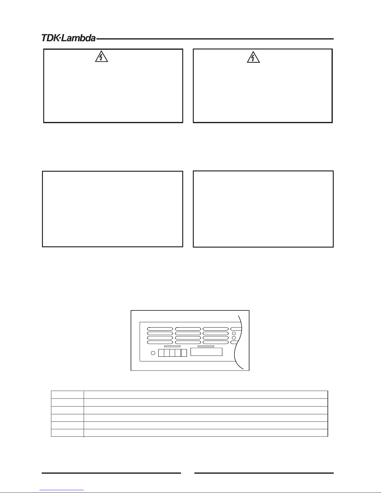
OUTPUT TERMINAL GROUNDING
There is a potential shock hazard at the RS232/485
and the IEEE ports when using power supplies with
rated or combined voltage greater than 400V with
the Positive Output of the power supplies is
grounded. Do not connect the Positive Output to
ground when using the RS232/485 or IEEE under
An RS232/485- und IEEE-Schnittstellen besteht die
Gefahr eines elektrischen Schlags, wenn Netzteile
mit Nennausgangsspannung oder einer in Reihe
verschalteten Spannung von mehr als 400V mit
geerdetem Plus-Ausgang betrieben werden.
Verbinden Sie daher nicht den Plus-Ausgang mit
Erde, wenn Sie die RS232/485- oder IEEESchnittstellen wie obern beschrieben verwenden.
3.10 LOCAL AND REMOTE SENSING
The rear panel J2 sense connector is used to configure the power supply for local or remote
sensing of the output voltage. Refer toFig.3-14 for sense connector location.
There is a potential shock hazard at the sense
connector when using a power supply with a rated
output voltage greater than 40V. Local sense and
remote sense wires should have a minimum
insulation rating equivalent or greater than the
maximum output voltage of the power supply. Ensure
that the connections at the load end are shielded to
prevent accidental contact with hazardous voltages.
An den Anschl ssen f r die Sense-Leitungen
besteht bei Stromversorgungen mit einer
Nennausgangsspannung von mehr als 40V die
Gefahr eines elektrischen Schlags. Sense-Leitungen
f r lokales wie f r Remote-Sensing sollten eine
Isolierung aufweisen, die mindestens f r die
maximal m gliche Ausgangsspannung des Netzteils
ausgelegt ist. Stellen Sie sicher, dass die
Verbindungen an der Last gegen versehentliches
Ber hren bei gef hrlichen Spannungen isoliert sind.
3.10.2 Local sensing
The power supply is shipped with the rear panel J2 sense connector wired for local sensing of the
output voltage. See Table 3-4 for J2 terminals assignment. With local sensing , the output voltage
regulation is made at the output terminals. This method does not compensate for voltage drop on
the load wires, therefore it is recommended only for low load current applications or where the load
regulation is less critical.
3.10.1 Sense wiring
Table 3-4: J2 terminals
Fig.3-15: Sense connector location
Function
Remote positive sense (+S).
Local positive sense. Connected internally to the positive output terminal (+LS).
Not connected (NC).
Local negative sense. Connected internally to the negative output terminal (-LS).
Remote negative sense (-S).
Terminal
J2-1
J2-2
J2-3
J2-4
J2-5
+S +LS
NC
-LS
-S
1
2
3
4
5
6
7
8
9
ON
OFF
SW1
J2
WARNING
WARNING
WARNUNG
WARNUNG
ERDUNG DER AUSGANGSKLEMMEN
26
Page 35
There is a potential shock hazard at the sense point
when using power supply with a rated output voltage
greater than 40V. Ensure that the connections at the
load end are shielded to prevent accidental contact
with hazardous voltages.
When using shielded sense wires, ground the shield in
one place only. The location can be the power supply
chassis or one of the output terminals.
3.10.3 Remote sensing
Use remote sense where the load regulation at the load end is critical. In remote sense, the power
supply will compensate for voltage drop on the load wires. Refer to the power supply specifications
for the maximum voltage drop on load wires. The voltage drop is subtracted from the total voltage
available at the output. Follow the instructions below to configure the power supply for remote
sensing:
1. Ensure that the AC On/Off is in the Off position.
2. Remove the local sense jumpers from J2.
3. Connect the negative sense lead to terminal J2-5 (-S) and the positive senselead to terminal
J2-1(+S) of the J2 mating connector. Ensure that theJ2 mating connectoris plugged securely
into the rear panel sense connector,J2.
4. TurnOn the power supply.
- J2 connector type: MC 1.5/5-G-3.81, Phoenix.
- Plug type: MC 1.5/5-ST-3.81, Phoenix.
- Wire AWG; 28 up to 16.
- Strippinglength: 7mm.
- Tightening torque:1.95-2.21Lb-Inch. (
To ensure safe transportation of the instrument, contact the Lambda sales or service facility near
you for Return Authorization and shipping information. Please attach a tag to the power supply
describing the problem and specifying the owner, model number and serial number of the power
supply. Refer to Warranty Information forfurther instructions.
3.10.4 J2 sense connector technical information
3.11 REPACKAGING FOR SHIPMENT
0.22- 0.25Nm)
Notes:
1.If the power supply is operating in remote sense
and either the positive or negative load wire is
not connected, an internal protection circuit will
activate and shut down the power supply. To
resume operation, turn the AC On/Off to the Off
position, connect the open load wire, and turn
On the power supply.
2.If the power supply is operated without the
remote sense lines or local sense jumpers, it will
continue to work, but the output voltage
regulation will be degraded. Also, the OVP
circuit may activate and shut down the power
supply.
WARNING
CAUTION
VORSICHT
WARNUNG
An den Anschlüssen für die Sense-Leitungen besteht
bei Stromversorgungen mit einer
Nennausgangsspannung von mehr als 40 V die
Gefahr eines elektrischen Schlags. Stellen Sie sicher,
dass die Verbindungen an der Last gegen
versehentliches Berühren bei gefährlichen
Spannungen isoliert sind.
Wenn Sie abgeschirmte Sense-Leitungen verwenden,
erden Sie die Abschirmung nur an einer Seite. Dies
kann entweder das Gehäuse des Netzteils oder eine
der Ausgangsklemmen sein.
Hinweise:
1.Wird das Netzteil mit " Remote-Sensing" betrieben
und entweder das negative oder das positive
Lastkabel ist nicht angeschlossen, schalted das
Netzteil ab. Um den Betrieb wieder aufzunehmen,
schalten Sie den Netz-On/Off-Schalter auf "Off" ,
verbinden das Lastkabel und schalten das Netzteil
wieder ein.
2.Wenn das Netzteil ohne die Remote-Sense Leitungen betrieben wird oder der Jumper J2 für
lokales Sensing offen ist, arbeitet das Netzteil weiter,
allerdings mit einer verminderten Regelgenauigkeit
der Ausgangsspannung. Zudem kann der
Überspannungsschutz OVP auslösen und das Netzteil
abschalten.
27
Page 36
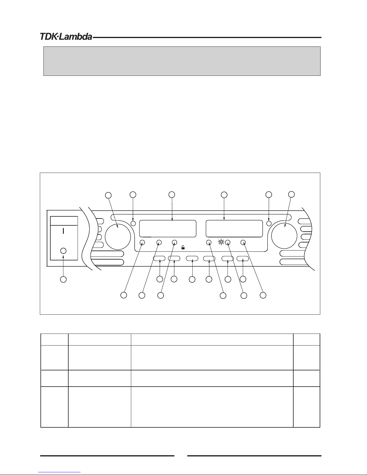
CHAPTER 4 FRONT AND REAR PANEL CONTROLS
AND CONNECTORS
4.1 INTRODUCTION
4.2 FRONT PANEL CONTROLS AND INDICATORS
The Genesys Power Supply series has a full set of controls, indicators and connectors that allow
the user to easily setup and operate the unit. Before starting to operate the unit, please read the
following sections for explanation of the functions of the controls and connectors terminals.
- Section 4.2: Front panel controls and indicators.
- Section 4.3: Rear panel controls and connectors.
See Fig.4-1 to review the controls, indicators and meters located on the power supply front panel.
TM
Fig.4-1: Front panel controls and indicators
1
Number
Control/Indicator
Description
Section
High resolution rotary encoder for adjusting the Output
Voltage. Also adjusts the OVP/UVL levels and selects
theAddress.
VOLTAGE control
VOLTAGE indicator
Green LED , lights for Constant-Voltage mode
operation.
2
3
VOLTAGE display
4 digit, 7-segment LED display. Normally displays the
output voltage. When the PREV button is pressed, the
display indicates the programmed setting of the output
voltage. When the OVP/UVL button is pressed, the
Voltage display indicates the OVP/UVLsetting.
Table 4-1: Front Panel controls and indicators
VOLTAGE
ALARM
FINE
PREV/
OVP
UVL
FOLD
REM/LOC
OUT
DC AMPS
CURRENT
'
'
'
'
'
'
'
'
DC VOLTS
POWER
1
14
17
18
19
2
15
16
3
13
10
4
11
5
12
9
6
7
8
5.2.1
5.3.1
5.4.1
7.2.2
28
Page 37

4
Number Control/Indicator Description
Section
4 digit, 7-segment LED display. Normally displays the
output current. When the PREV button is pressed, the
display indicates the programmed setting of output
current.
CURRENT display
6
CURRENT control
High resolution rotary encoder for adjusting the Output
Current. Also selects the Baud-Rate of the
communication port.
Table 4-1: Front Panel controls and indicators
5
CURRENT indicator
Green LED, lights for Constant-Current mode operation.
Main function
Auxiliary function
: Output ON/OFF control. Press OUT to
set the output On or Off. Press to reset and turn On the
output after OVP or FOLD alarm events have occurred.
: Selects between "Safe-Start" and
"Auto-Restart" modes. Press and hold OUT button to
toggle between "Safe-Start" and "Auto-Restart".The
VOLT display will cycle between "SAF" and "AU7”.
Releasing the OUT button while one of the modes is
displayed, selects that mode.
OUT button
OUT indicator
Green LED, lights when Foldback protection is On.
Over VoltageProtection and Under Voltage limit setting.
- Press once to set OVPusing VOLTAGE encoder ( the
current display shows “OUP” )
- Press again to set the UVLusing VOLTAGE encoder
( the current display shows “UUL” ).
Main function
Auxiliary function
: Go to local. Press REM/LOC to put the
unit into Local (REM/LOC button is disabled at Local
Lockout mode).
: Address and Baud Rate setting.
Press and hold REM/LOC for 3sec. to set the Address
with the VOLTAGE encoder and the Baud Rate with the
CURRENT encoder.
Green LED, lights when the unit is in Remote mode.
Foldback protection control.
- Press FOLD to set Foldback protection to On.
- To release Foldback alarm event, press OUT to
enable the output and re-arm the protection.
- Press FOLD again to cancel the Foldback protection.
Main function
Auxiliary function
: Press PREV to display the output
voltage and current limit setting. For 5 sec. the display
will show the setting and then it will return to show the
actual output voltage and current.
: Front Panel Lock. Press and hold
PREV button to toggle between “Locked front panel”
and “Unlocked front panel”. The display will cycle
between “LFP” and “UFP”. Releasing the PREV button
while one of the modes is displayed, selects that mode.
REM/LOC button
REM/LOC indicator
FOLD button
FOLD indicator
OVP/UVL button
PREV/ button
Green LED, lights when the DC output is enabled.
7
8
9
10
11
12
13
14
5.2.2
7.2.4
5.6
7.2.5
5.11
7.2.2
7.2.4
5.5
5.3
5.4
5.17
29
Page 38
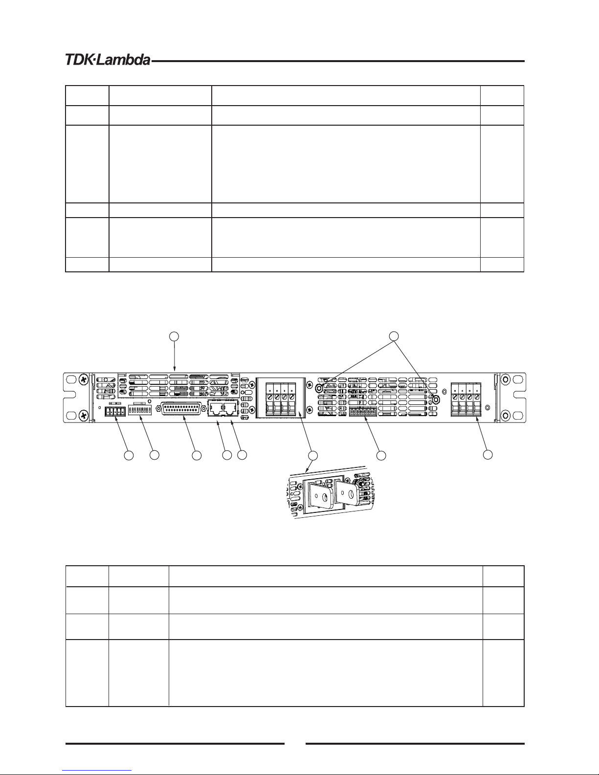
16
Number Control/Indicator Description
Section
FINE button
18
ALARM indicator
Table 4-1: Front Panel controls and indicators
17
FINE indicator
AC Power switch
19
Voltage and Current Fine/Coarse adjustment control.
Operates as a toggle switch. In Fine mode, the
VOLTAGE and CURRENT encoders operate with high
resolution and in Coarse mode with lower resolution
(approx. 6 turns).
: Advanced Parallel Operation
Mode setting.
Auxiliary function
Green LED, lights when the unit is in Fine mode.
Red LED, blinks in case of fault detection. OVP, OTP
Foldback, Enable and AC fail detection will cause the
ALARM LED to blink.
AC On/Off control.
4.3 REAR PANEL
See Fig.4-2 to review the connections and controls located on the power supply rear panel.
Refer to Table 4-2 for explanations about the rear panel connections and controls.
Fig.4-2: Rear panel connections and controls
8~100V
Models
150-600V
Models (shown)
1
Number
Item
Description
Section
AC input
connector
2
DC output
Table 4-2: Rear panel connections and controls
3
Header with a screw plug connector (Phoenix Contact
PC6-16/4-GF-10,16)
3.7
Bus-bars for 8V to 100V models.
Wire clamp connector for 150V to 600V models (shown).
3.9.6
RJ-45 type connector, use for connecting power supplies to
RS232 or RS485 port of computer for remote control purposes.
When using several power supplies in a power system, the first
unit Remote-In is connected to the computer and the remaining
units are chained, Remote-In to Remote-Out.
Remote-In
connector
7.3
7.4
Green LED, lights when PREV button is pressed.
PREV indicator
15
10
8
9
1
5
7
3
4
6
2
5.15.2
J2
J1
ON
OFF
J3
SW1
J1
OUT
IN
AC INPUT
30
Page 39
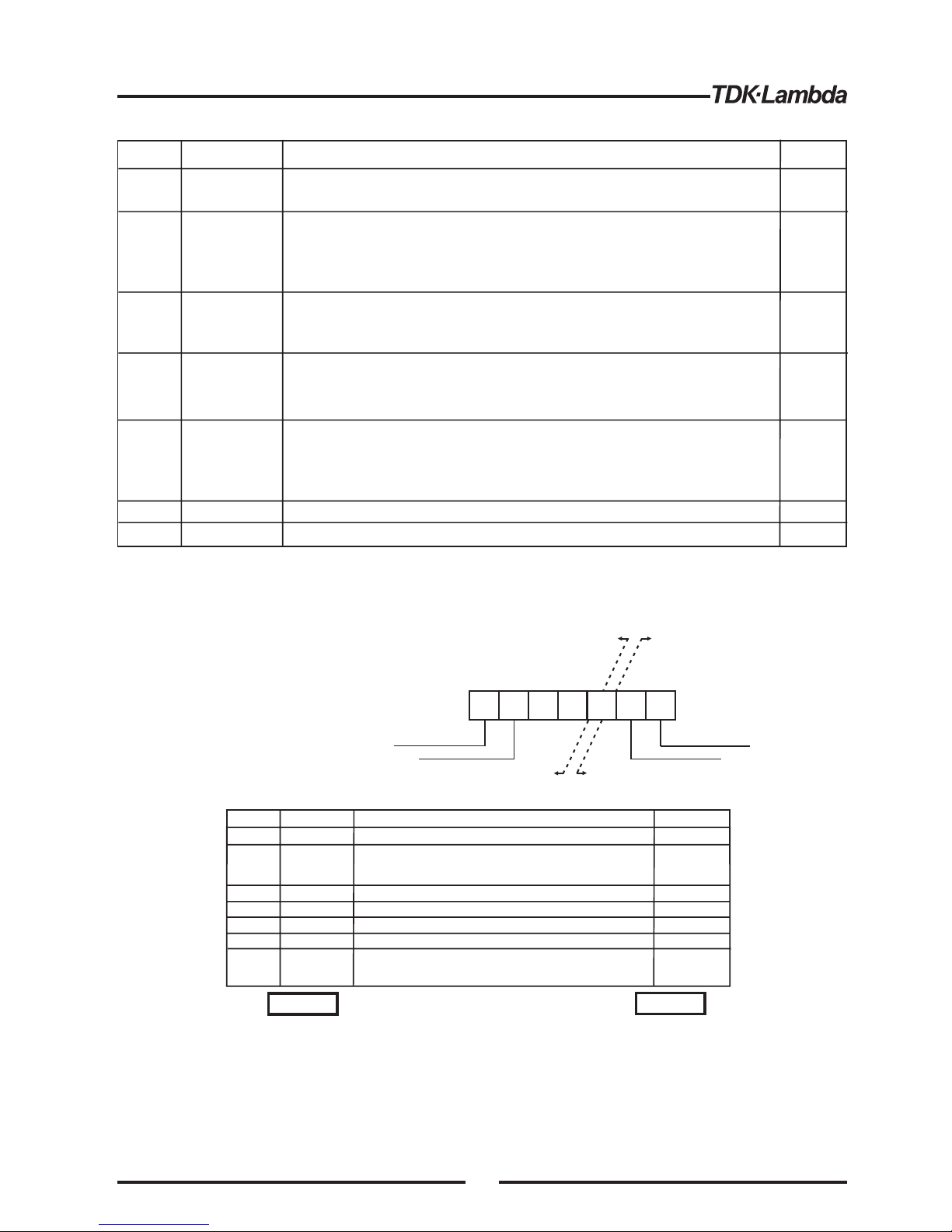
1
2
3
4
5
6
7
Sec. 5.7, 5.10
Sec. 6.2, 5.9,
6.6
IF_COM
+5V
+5V+/-5% MAX CURRENT 0.2A
+15V+/-5% MAX CURRENT 0.2A
Isolated Interface Common Return for the SO, ENA
control, PS_OK signal and for the RS232/485 optional
IEEE interface.
NC
NC
+15
NC
COM
Control Common. Return for VMON, IMON, CV/CC,
LOC/REM. Referenced internally to the negative output
potential.
Terminal
Signal name
Function
Reference
The COM terminal (Pin 7) is referenced internally to the -V
potential (and J1 Pin 12) of the power supply. Do not
attempt to bias any of these terminals relative to the -V or
any other potential. Use the Isolated Programming
interface option to allow control from a programming
source at a different potential .
Table 4-2: Rear panel connections and controls
RJ-45 type connector, used for chaining power supplies to form
a serial communication bus.
Connector for remote analog interface. Includes output voltage and
current limit programming and monitoring signals, Shut-off control
(electrical signal), Enable/Disable control (dry-contact), power
supply ok (PS_OK) signal and operation mode (CV/CC) signal.
Nine position DIP switch for selecting remote programming and
monitoring modes for Output Voltage, Current Limit and other
control functions.
Blank sub-plate for standard units (shown). Isolated Remote
Analog programming connector for units equipped with
Isolated Analog control option. IEEE connector for units
equipped with IEEE programming option.
M4 stud and hardware for chassis ground connection.
Number
Item
Description
Section
4.5
4.3.1
Connector for making remote sensing connections to the load
for regulation of the load voltage and compensation of load
wire drop.
4.4
4.4.1
4.4.2
3.8.2
3.10.2
3.10.3
4
5
6
7
8
10
9
Remote Out
connector
Programming
and
Monitoring
connector
SW1 Setup
switch
Remote
sense
connector
Blank
Sub-plate
Ground stud
Auxiliary
Auxiliary Power Supply
7.3
7.4
1
2
3
4
5
6
7
+5V
IF_COM
+15V
COM
Same ground
as P/S negative
output
Isolated from
PS outputs,
same ground
as RS232/485
4.3.1 Auxiliary Power Supply
There are two Auxiliary outputs provided:
+5V Output Max output current is 0.2A
+15V Output Max output current is 0.2A
The Auxiliary output voltage considered as limited power source.
4.3.1.1 Connector detail:
4.3.1.2 Connector functions description:
CAUTION
VORSICHT
Der COM-Anschluss (Pin 7) ist intern mit dem "-V" -Potential
des Netzteils (und dem Pin 12 von J1) verbunden. Versuchen
Sie nicht, zwischen einem dieser Anschl
I I
I
üsse und -V oder
einem anderen Potential eine Spannung aufzubauen.
Verwenden Sie die Option " solated Programming nterface "
( solierte Programmierschnittstelle), wenn Sie das Netzteil von
einem Gerät mit einem anderen Potential aus steuern wollen.
31
Page 40
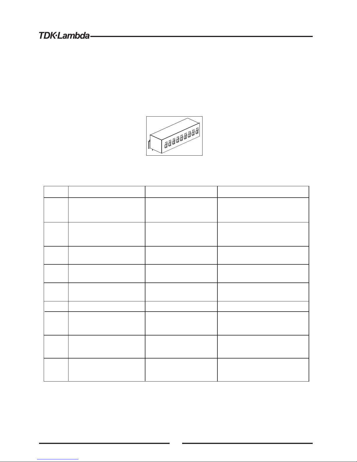
4.4.2 Resetting the SW1 switch
Before making any changes to the SW1 switch setting, disable the power supply output by
pressing the front panel OUT button. Ensure that the output voltage falls to zero and OUT LED is
off, then use any small flat-bladed screwdriver to change the SW1 switch setting.
Table 4-3: SW1 positions functions
Position
Function
SW1-1
SW1-2
SW1-3
Output Voltage
Remote analog programming
Output Current Limit
Remote analog programming
Programming range select
(Remote voltage/resistive)
Output Voltage and
Current Monitoring range
Shut Off logic select
RS232/485 select
Output Voltage
Resistive programming
Output Current Limit
Resistive programming
Enable/Disable control
Up
Output Voltage
Programmed by remote analog
External Voltage or Extenal Resistor
Output Current Limit
Programmed by remote analog
External Voltage or External Resistor
0-10V / (0-10Kohm)
0-10V
On: High (2-15V) or Open
Off: Low (0-0.6V) or Short
RS485 interface
Output Voltage
Programmed by
External Resistor
Output Current Limit
Programmed by
External Resistor
Rear panel
Enable/Disable control is
active
Down (Factory default)
Output Voltage
Programmed by
Front Panel
Output Current Limit
Programmed by
Front Panel
0-5V / (0-5Kohm)
0-5V
On: Low (0-0.6V) or Short
Off: High (2-15V) or Open
RS232 interface
Output Voltage
Programmed by
External Voltage
Output Current Limit
Programmed by
External Voltage
Rear panel
Enable/Disable control is
not active
SW1-4
SW1-5
SW1-6
SW1-7
SW1-8
SW1-9
4.4.1 SW1 position functions
Refer to Table 4-3 for description of SW1 position functions. The factory default setting is Down
for all positions.
4.4 REAR PANEL SW1 SETUP SWITCH
The SW1 Setup switch (see Fig.4-3) is a 9-position DIP switch that allows the user to choose the
following:
- Internal or remote programming for Output Voltage and Current Limit.
- Remote voltage or resistive programming of Output Voltage and Output Current limit.
- Select range of remote voltage and resistive programming.
- Select range of Output Voltage and Output Current monitoring.
- Select the Remote Shut-Off control logic.
- Select between RS232 or RS485 communication interface.
- Enable or disable the rear panel Enable/Disable control (dry contact).
Fig.4-3: SW1 setup DIP switch
1
2
3
4
5
6
7
8
9
32
Page 41
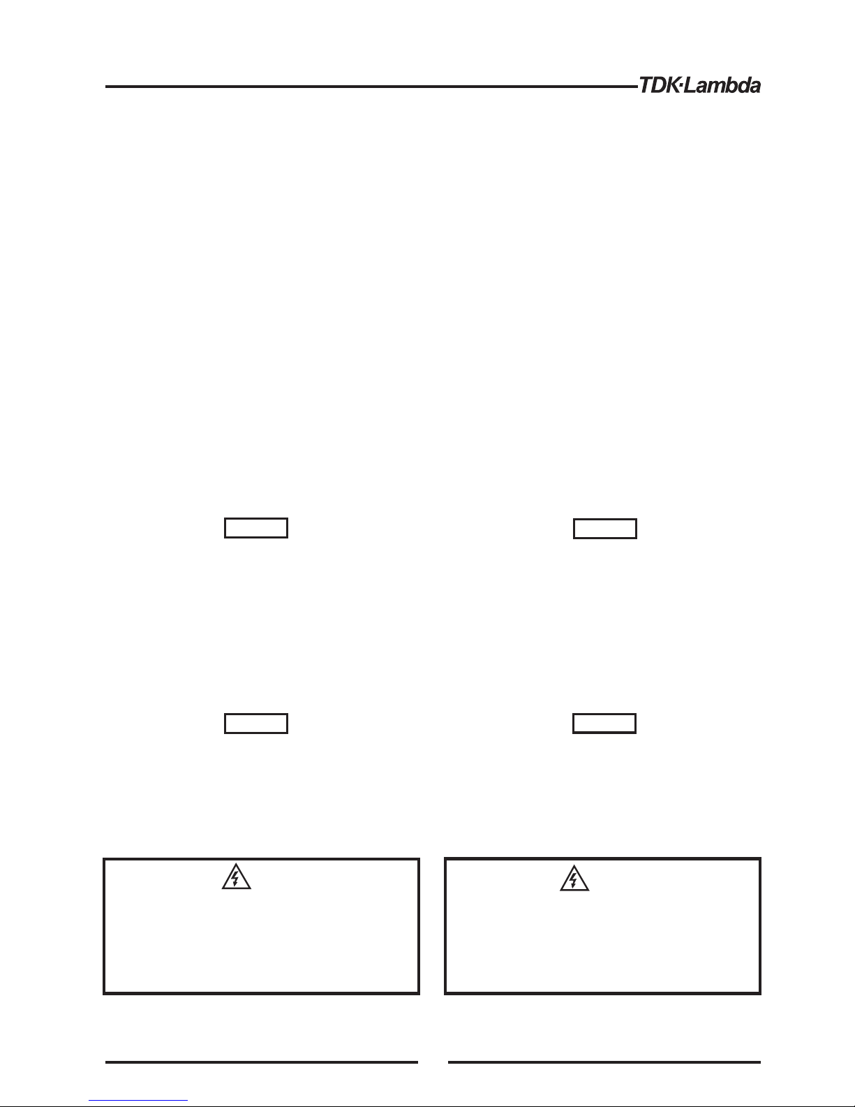
4.5 REAR PANEL J1 PROGRAMMING AND MONITORING CONNECTOR
The J1 Programming and Monitoring connector is a DB25 subminiature connector located on the
power supply rear panel. Refer to Table 4-4 for description of the connector functions. The power
supply default configuration is Local operation which does not require connections to J1. For remote
operation using J1 signals use the plug provided with power supply or equivalent type. It is essential
to use plastic body plug to conform with Safety Agency requirements. If a shield is required for J1
wires, connect the shield to a power supply chassis ground screw.
- J1 connector type: AMP, P/N: 5747461-3
- J1 plug description: AMP, P/N: 745211-7
- Wire dimension range: AWG26-22
- Extraction tool: AMP,91232-1 or equivalent.
- Manual Pistol grip tool:
Handle:AMP, P/N: 58074-1
Head:AMP, P/N: 58063-2
Before making any connection, turn the AC On/Off switch to the Off position and wait until the front
panel display has turned Off.
4.5.1 Making J1 connections
To prevent ground loops and to maintain the isolation of
the power supply when programming from J1, use an
ungrounded programming source.
The programming return terminals (12, 22 and 23) are
referenced to the -V potential of the power supply. Do not
attempt to bias any of these terminals relative to the -V or
any other potential. Use the Isolated Programming
interface option to allow control from a programming
source at a different potential relative to the power supply
negative output.
There is a potential shock hazard at the output when
using a power supply with rated output greater than
40V. Use wires with minimum insulation rating
equivalent to the maximum output voltage of the power
supply.
WARNING
WARNUNG
CAUTION
CAUTION
VORSICHT
VORSICHT
Die Return-Anschl 1
I
I I
üsse (Pins 2, 22 und 23) sind mit
dem "-V" -Potential des Netzteils verbunden. Versuchen
Sie nicht, zwischen einem dieser Anschlüsse und -V oder
einem anderen Potential eine Spannung aufzubauen.
Verwenden Sie die Option " solated Programming
nterface" ( solierte Programmierschnittstelle), wenn Sie
das Netzteil von einem Gerät mit einem anderen
Potential (gegenüber dem Minus-Ausgang des Netzteils)
aus steuern wollen.
Wenn Sie das Netzteil über J steuern, verwenden Sie
eine potentialfreie Signalquelle, um Erdschleifen zu
vermeiden und die solation des Netzteils zu erhalten.
1
I
Bei Stromversorgungen mit einer
Nennausgangsspannung von mehr als 40V besteht
am Ausgang grundsIätzlich die Gefahr eines
elektrischen Schlags. Verwenden Sie Kabel, deren
solation mindestens für die maximale
Ausgangsspannung des Netzteils ausgelegt ist.
33
Page 42
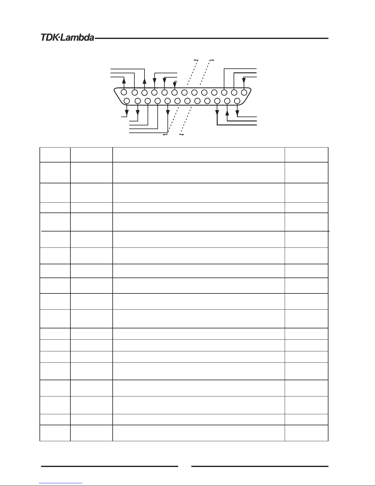
Fig.4-4: J1 connector terminals and functions
14
15
16
17
18
19
20
21
22
23
24
25
1
2
3
4
5
6
7
8
10
11
12
13
9
Same ground
as P/S negative
output
Isolated from
PS outputs,
same ground
as RS232/485
IMON
IPGM_RTN
VPGM_RTN
LOC/REM SIGNAL
IF_COM
IF_COM
ENA_IN
VMON
COM
CV/CC
IPGM
VPGM
LOC/
REM
P
ENA_OUT
SO
PS_OK
Table 4-4: J1 connector terminals and functions
Enable /Disable the power supply output by dry-contact
(short/open) with ENA_OUT.
Isolated Interface Common. Return for the SO control,
PS_OK signal and for the optional IEEE interface.
No Connection
Input for selecting between Local or Remote analog
programming of output voltage and output current.
Input for remote analog voltage/resistance programming
of the Output Voltage.
Input for remote analog voltage/resistance programming
of the Output Current.
Output for monitoring the power supply Output Voltage.
Output for Constant-Voltage / Constant-Current mode
indication.
Enable/Disable the power supply output by dry-contact
(short/open) with ENA_IN.
Input for Shut-Off control of the power supply output.
Output for indication of the power supply status.
No Connection.
Output for indicating if the unit is in Local or Remote
analog programming mode.
Output for monitoring the power supply Output Current.
Output for current balance in parallel operation.
Connected internally to J1-24 terminal.
Control Common. Return for VMON, IMON, CV/CC, LOC/REM.
Referenced
internally to the negative output potential.
Return for VPGM input. Connected internally to J1-12
terminal.
Return for IPGM input. Referenced internally to the
negative output potential.
J1-1
J1-2
J1-3
J1-4~7
J1-8
J1-17~20
J1-22
J1-21
J1-23
J1-24
J1-25
J1-16
J1-15
J1-14
J1-13
J1-9
J1-10
J1-11
J1-12
Sec. 5.8
Sec. 5.7, 5.10
Sec. 6.1~6.4
Sec. 6.1~6.4
Sec. 6.6
Sec. 6.2
Sec. 5.9
Sec. 5.8
Sec. 5.7
Sec. 5.10
Sec. 6.3
Sec. 6.1, 6.4,
6.5
Sec. 6.1, 6.4,
6.5
Sec. 6.6
Sec. 5.15
ENA_IN
IF_COM
N/C
LOCAL/
REMOTE
VPGM
IPGM
VMON
COM
CV/CC
ENA_OUT
SO
PS_OK
N/C
LOC/REM
SIGNAL
VPGM_RTN
IPGM_RTN
IMON
P
J1
contact
Signal
name
Function
Reference
34
Page 43

CHAPTER 5 LOCAL OPERATION
5.1 INTRODUCTION
5.2 STANDARD OPERATION
This Chapter describes the operating modes that are not involved in programming and monitoring
the power supply via its serial communication port (RS232/RS485) or by remote analog signals.
Ensure that the REM/LOC LED on the front panel is Off, indicating Local mode. If the REM/LOC
LED is On, press the front panel REM/LOC button to change the operating mode to local.
- For information regarding remote analog programming refer to Chapter 6.
- For information regarding usage of the serial communication port refer to Chapter 7.
The power supply has two basic operating modes: Constant Voltage Mode and Constant Current
Mode. The mode in which the power supply operates at any given time depends on the output
voltage setting, output current limit setting and the load resistance.
1. In constant voltage mode, the power supply regulates the output voltage at the selected value,
while the load current varies as required by the load.
2. While the power supply operates in constant voltage mode, the VOLTAGE LED on the front panel
illuminates.
3.Adjustment of the output voltage can be made when the power supply output is enabled
(Output On) or disabled (Output Off).When the output is enabled, simply rotate the VOLTAGE
encoder knob to program the output voltage. When the output is disabled, press the PREV
button and then rotate the VOLTAGE encoder knob. The VOLTAGE meter will show the
programmed output voltage for 5 seconds afterthe adjustment has been completed. Then the
VOLTAGEmeter will display "OFF".
4.Adjustment resolution can be set to coarse or fine resolution.
Press FINE button to select between the lower and higher resolution. The FINE LED turns On
when the resolution is set to FINE.
5.2.1 Constant Voltage Mode
If after completing the adjustment, the display shows a different value
than the setting, the power supply may be at current limit. Check the
load condition and the power supply current limit setting.
The maximum and minimum setting values of the output voltage are
limited by the Over Volt
age protection and Under Voltage limit setting.
Refer to Sec.5.3 and 5.4 for more details.
NOTE
NOTE
5.2.2 Constant Current Operation
1. In constant current mode, the power supply regulates the output current at the selected value,
while the voltage varies with the load requirement.
2. While the power supply is operating in constant current mode, the CURRENT LED on the front
panel illuminates.
3.Adjustment of the output current limit can be made when the power supply output is enabled
(Output On) or disabled (Output Off).
- Disabled output (Off): Press PREV button and then rotate the Current encoder knob. The
CURRENT meter will show the programmed current limit for 5 seconds after the adjustment
has been completed. Then the VOLTAGE meter will display "OFF".
35
Page 44

- Enabled output, power supply in Constant Voltage mode: Press the PREV button and then
rotate the CURRENT encoder knob. The CURRENT meter will show the programmed
current limit for 5 seconds after the adjustment has been completed, and then will return to
show the actual load current.
- Enabled output, power supply in Constant Current mode: Rotate the CURRENT encoder
knob to adjust the current limit.
4. Adjustment resolution can be set to Coarse or Fine adjustment. Press the FINE button to
select between the Coarse and Fine resolution. The FINE LED turns On when the resolution
is set to FINE.
If the power supply operates in Constant Voltagemode, while the load current is increased to greater
than the current limit setting, the power supply will automatically switch to Constant Current mode. If
the load is decreased to less than the current limit setting, the power supply will automatically switch
back to Constant Voltagemode.
The OVP circuit protects the load in the event of a remote or local programming error or a power
supply failure. The protection circuit monitors the voltage at the power supply sense points and thus
providing the protection level at the load. Upon detection of an Over Voltage condition, the power
supply output will shut down.
The OVP can be set when the power supply output is Enabled (On) or Disabled (Off). To set the OVP
level, press the OVP/UVL button, so that theCURRENTmeter shows "OUP".
The VOLTAGE meter shows the OVP setting level. Rotate the VOLTAGE encoder knob to adjust the
OVP level. The display will show "OUP" and the setting value for 5 seconds after the adjustment has
been completed and then will return to it's previous state.
The minimum setting level is approx. 105% of the set output voltage, or the value in Table 7-6,
whichever is higher.The maximum setting level is shown in Table 5-1.
5.2.3 Automatic Crossover
5.3.1 Setting the OVP level
5.3 OVER VOLTAGE PROTECTION (OVP)
Table 5-1: Maximum OVP setting levels
5.3.2 Activated OVP protection indications
5.3.3 Resetting the OVP circuit
When the OVP is activated the power supply
output shuts down. The VOLTAGE display shows
"OUP" and the ALARM LED blinks.
To reset the OVP circuit after it activates:
1. Reduce the power supply Output Voltage setting below theOVP set level.
2. Ensure that the load and the sense wiring is connected properly.
3. There are four methods to reset the OVP circuit.
3.1 Press OUT button.
3.2 Turnthe power supply Off using theAC On/Offswitch, wait until the front panel display turns
Off, then turn the power supply On using theAC On/Off switch.
3.3 Turnthe power supply output Off and then On using the SO control (refer to sect.5.7). In this
method the power supply should be set toAuto-Restart mode.
3.4 Send OUT1 command via the RS232/485 communication port.
60V
80V
100V
150V
300V
600V
66.0V
88.0V
110.0V
165.0V
330.0V
660.0V
Model
Max.
OVP
8V
10V
16V
20V
30V
40V
10.0V
12.0V
19.0V
24.0V
36.0V
44.0V
Model
Max.
OVP
To preview t he OVP setting, press OVP/UVL
pushbutton so that the CURRENT display will show
"OUP".At this time, the VOLTAGE display will show the
OVP setting. After 5 seconds, the display will return to
it's previous state.
36
Page 45

5.4 UNDER VOLTAGE LIMIT (UVL)
5.5 FOLDBACK PROTECTION
5.6 OUTPUT ON/OFF CONTROL
5.7 OUTPUT SHUT-OFF (SO) CONTROL VIA REAR PANEL J1 CONNECTOR
The UVL prevents adjustment of the output voltage below a certain limit.The combination of UVL
and OVP functions, allow the user to create a protection window for sensitive load circuitry.
Setting the UVL can be made when the power supply output is Enabled (On) or Disabled (Off). To set
the UVL level, press the OVP/UVL button TWICE, so that the CURRENT meter shows “UUL”. The
VOLTAGE meter shows the UVLsetting level. Rotate the VOLTAGE encoder knob to adjust the UVL
level. The display will show “UUL” and the setting value for 5 seconds after the adjustment has been
completed and then will return to it’s previous state.
UVL setting values are limited at the maximum level to approximately 95% of the Output Voltage
setting. Attempting to adjust the UVL above this limit will result in no response to the adjustment
attempt. The minimum UVL setting is zero.
5.4.1 Setting the UVL level
Foldback protection will shut down the power supply output if the load current exceeds the current limit
setting level. This protection is useful when the load circuitry is sensitive to an over current condition.
To arm the Foldback protection, the FOLD button should be pressed so that the FOLD LED illuminates.
In this condition, transition from Constant Voltage to Constant Current mode will activate the Foldback
protection.Activation of the Foldback protection disables the power supply output, causes the ALARM
LED to blink and display " Fb" on the VOLTAGEmeter.
There are four methods to reset an activated Foldback protection.
1. Press the OUT button. The power supply output is enabledand theOutput Voltage and current
will return to their last setting. In this method, the Foldback protection remains armed, therefore if
the load current is higher than the current limit setting, the Foldback protection will be activated
again.
2. Press the FOLD button to cancel the Foldback protection. The power supply output will be disabled
and the VOLTAGE display will show “OFF”. Press the OUT button to enable thepower supply output.
3. Turnthe powersupply outputOff and thenOn usingthe SO control (refer to sect. 5.7). In this method
the foldback protection remains armed, therefore if the load current is higher than the current limit
setting the Foldback protection will be activated.
4. Turnthe powersupply Offusing the AC On/Off switch, wait until the front panel display turns Off,
then turn the unit back ON again. The power supply output is enabled and the Output Voltage and
Current will return to their last setting. In this method, the Foldback protection remains armed,
therefore if the load current is higher than the current limit setting, the Foldback protection will be
activated again.
The Output On/Off enables or disables the power supply output. Use this function to make adjustments
to either the power supply or the load without shutting off the AC power. The Output On/Off can be
activated from the front panel using the OUT button or from the rear panel J1 connector.The OUT
button can be pressed at any time to enable or disable the power supply output. When the output is
disabled, the output voltage and current fall to zeroand the VOLTAGE display shows “OFF”.
Contacts 2,3 and 15 of J1 (Fig.4-2, Item 5) serve as Output Shut-Off (SO) terminals. The SO terminals
accept a 2.5V to 15V signal or Open-Short contact to disable or enable the power supply output. The
SO function will be activated only when a transition from On to Off is detected after applyingAC power
to unit. (Thus , inAuto-Restart mode, the output will be enabled after applyingAC power, even if SO is in
Off level.). After On to Off transition is detected, the SO will enable or disable the power supply output
according to the signal level or the short/open applied to J1. This function is useful for connecting power
supplies in a “Daisy-chain” (refer to section 5.16). The SO control can be used also to reset the OVP
and Fold Protection. Refer to sect. 5.3 and 5.5 for details.
5.5.1 Setting the Foldback protection
5.5.2 Resetting activated Foldback protection
37
Page 46
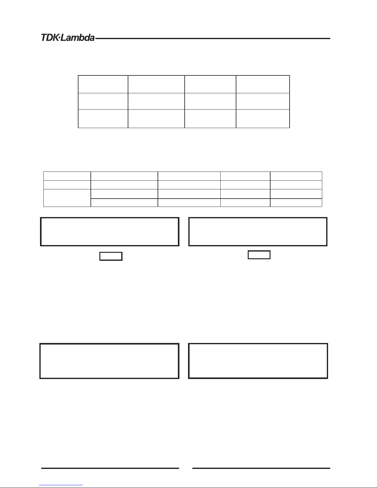
When the unit is shut-off by J1 signal, the VOLTAGE display will show “SO” to indicate the unit state. J1
contact 15 is the SO signal input and contacts 2 and 3, IF_COM, are the signal return (connected
internally). Contacts 2,3 and 15 are optically isolated from the power supply output.
The SO control logic can be selected by the rear panel SW1 Setup switch. Refer to Table 5-2 for SW1
Table 5-2: SO logic selection
SW1-5 setting
Down (default)
Up
SO signal level
J1-2(3), 15
2-15V or Open
0-0.6V or Short
2-15V or Open
0-0.6V or Short
Power supply
output
On
Off
Off
On
Display
Voltage/Current
“SO”
“SO”
Voltage/Current
5.8 ENABLE/DISABLE CONTROL VIA REAR PANEL J1 CONNECTOR
Contacts 1 and 14 of J1 (Fig.4-2, Item 5) serve as Output Enable/Disable terminals by switch or relay.
This function is enabled or disabled by the SW1 Setup switch position 9. Refer to Table 5-3 for
Enable/Disable function and SW1 setting.
Table 5-3: Enable/Disable function and SW1 setting
SW1-9 setting
Down (Default)
Enable/Disable inputs
Open or Short
Open
Short
Power supply output
On
Off
On
Display
Voltage/Current
“ENA”
Voltage/Current
ALARM LED
Off
Blinking
Off
Up
5.9 CV/CC SIGNAL
5.10 PS_OK SIGNAL
CV/CC signal indicates the operating mode of the power supply, Constant Voltage or Constant Current.
CV/CC signal is an open collector output with a 30V parallel zener, at J1-13, referenced to the COM
potential at J1-12 (connected internally to the negative sense potential). When the power supply
operates in Constant Voltage mode, CV/CC output is open. When the power supply operates in Constant
Current mode, CV/CC signal output is low(0-0.6), with maximum 10mA sink current.
PS_OK signal indicates fault condition in the power supply. PS_OK is a TTL signal output at J1-16,
referenced to IF_COM at J1-2,3 (Isolated Interface Common)). When a fault condition occurs, PS_OK
level is low, with maximum sink current of 1mA, when no fault condition occurs, PS_OK level is high with
maximum source current of 2mA. The following faults will set the PS_OK to Fault state:
Safe Start mode
Auto Restart mode
-If the Enable/Disable fault condition
clears when units in safe start mode recovery is by
pressing OUT button or by sending a ‘OUT 1’ serial
command.
- The output will return back ON
automatically when the Enable/Disable fault conditions
clears.
To prevent possible damage to the unit, do not connect
any of the Enable/Disable inputs to the positive or
negative output potential.
Do not connect CV/CC signal to a voltage source
higher than 30VDC. Always connect CV/CC signal to
the voltage source with a series resistor to limit the
sink current to less than 10mA.
*OTP
*OVP
*Foldback
*AC fail
*Enable/Disable open (Power supply is disabled)
*SO (Rear panel Shut-Off - Power supply is shut off))
*IEEE failure (with optional IEEE interface)
*Output Off
CAUTION
CAUTION
VORSICHT
VORSICHT
Um das Gerät vor möglichen Schäden zu schützen,
verbinden Sie nie einen der Enable/Disable-Eingänge
mit dem Plus- oder Minus-Ausgangspotential.
Safe-Start-Modus - Im Safe-Start-Modus kehrt das
Netzteil erst dann in den Normalbetrieb zurück, wenn der
Enable/Disable-Eingang aktiviert wurde und zusätzlich die
OUT - Taste betätigt wird oder das Gerät ein "OUT1
“-Kommando über die serielle Schnittstelle empfängt.
- In diesem Modus kehrt das
Netzteil automatisch in den Normalbetrieb zurück, sobald
der Enable/Disable-Eingang aktiviert wurde.
Auto-Restart-Modus
Verbinden Sie den CV/CC-Ausgang nur mit einer
Spannungsquelle bis maximal 30V DC. Verbinden Sie
den Anschluss stets über einen Vorwiderstand mit der
Spannungsquelle, oder begrenzen Sie den Strom auf
andere Weise auf max. 10 mA.
HINWEIS
NOTE
38
Page 47

5.11 SAFE START AND AUTO-RESTART MODES
5.12 OVER TEMPERATURE PROTECTION (OTP)
5.13 LAST SETTING MEMOR
5.14 SERIES OPERATION
When turning on the power supply AC On/Off, it can start to its last setting of Output Voltage and
Current limit with the output enabled (Auto-restart) or start with the output disabled (Safe mode).
Press and hold the OUT button to select between Safe start andAuto-restart modes.The VOLTAGE
display will continuously cycle between "SAF" and "AU7” every 3 seconds. Releasing OUT
pushbutton while one of the modes is displayed, selects that mode. The default setting at shipment
is Safe mode.
In this mode, the power supply restores its last operation setting. Upon start-up, the output is
enabled or disabled according to itslast setting.
In this mode, the power supply restores its last operation setting and sets the Output to Off state. At
start-up, the output is disabled and the output voltage and current are zero. To enable the output and
restore the last output voltage and current limit values, momentarily press OUT button.
The OTP circuit shuts down the power supply before the internal components can exceed their safe
internal operating temperature. When an OTP shutdown occurs, the display shows "O7P" and the
ALARM LED blinks.
Resetting the OTP circuit can be automatic (non-latched) or manual (latched) depending on the
Safe orAutomatic restartmode.
In Safe start mode, the power supply stays off after the over temperature
condition has been removed. The display continue to shows "O7P" and the ALARM LED
continues to blink. To reset the OTP circuit, press OUT button (or send OUT ON command via the
serial port).
InAuto-restart mode , the power supply recovers to it's last setting
automatically when the over temperature condition is removed.
The power supply is equipped with Last Setting Memory, which stores power supply parameters at
eachAC turn-off sequence.
1. OUT On or Off
2. Output voltage setting (PV setting)
3. Output current limit (PC setting)
4. OVP setting
5. UVL setting
6. FOLD setting
7. Start-upmode (Safeor
Auto-restart)
8. Remote/Local:If the last setting was Local Lockout (latched mode), the supply will return to
Remote mode (non-latched).
9.Address setting
10. Baud rate
11. Locked /Unlocked front panel (LFP/UFP)
(Items 8, 9, 10 are related to Remote digital control operation and explained in chapter 7)
12. Master/Slave setting
Power supplies of the SAME MODEL can be connected in series to obtain increased output voltage.
Splitconnection ofthe power supplies gives positive and negativeoutput voltage.
5.11.1Automatic start mode
5.11.2Safe start mode
1. Safe start mode:
2. Auto-restartmode:
Y
STORED PARAMETERS:
39
Page 48
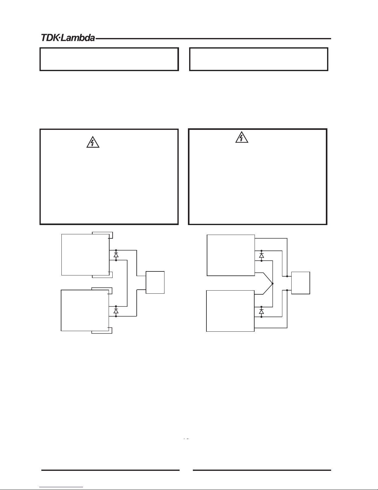
Do not connect power supplies from different
manufacturers in series or in parallel.
When power supplies are connected in series, and the
load or one of the output terminals is grounded, no
point may be at a greater potential of 60VDC from
ground for models up to 60VDC Rated Output and
600VDC from ground for models >60VDC Rated
Output. When using RS232/485 or IEEE, refer to the
OUTPUT TERMINALS G ROUNDING warning,
section 3.9.11.
5.14.1 Series connection for increased output voltage
In this mode, two units are connected so that their outputs are summed. Set the current limit of
each power supply to the maximum that the load can handle without damage. It is
recommended that diodes be connected in parallel with each unit output to prevent reverse
voltage during start up sequence or in case one of the units shuts down. Each diode should be
rated to at least the power supply rated output voltage and output current. Refer to Fig.5-1 and
5-2 for series operation with local and remote sensing.
+S
+
-
-S
-LS
+LS
POWER
SUPPLY
+S
+
+
-
-
-S
-LS
+LS
POWER
SUPPLY
LOAD
+S
+
-
-S
-LS
+LS
POWER
SUPPLY
+S
+
+
-
-
-S
-LS
+LS
POWER
SUPPLY
LOAD
Fig.5-1: Series connection, local sensing
Fig.5-2: Series connection, remote sensing
Remote programming in series operation for increased output voltage:
1.Programming by external voltage:
2.Using the SO function and PS_OK signal:
The analog programming circuits of this power supply
are referenced to the negative output potential.
Therefore, the circuits used to control each series
connected unit must be separated and floated from
each other.
The Shut-Off and PS_OK circuits are referenced to the
isolated interface common, IF_COM (J1-2,3). The
IF_COM terminals of different units can be connected
to obtain a single control circuit for the power supplies
connected in series.
(*)
(*)
(*)
(*)
(*) Diodes are
user supplied.
WARNING
CAUTION
VORSICHT
WARNUNG
Wenn Stromversorgungen in Reihe geschaltet werden
und die Last oder eine der Ausgangsklemmen geerdet
ist, stellen Sie sicher, dass
I
11.
• Modellen mit bis zu 60V DC
Nennausgangsspannung kein Punkt ein Potential
grö er als 60V gegenüber Erde ausweist,
• bei Modellen mit mehr als 60V DC
Nennausgangsspannung kein Punkt ein Potential
grö er als 600V gegenüber Erde ausweist.
bei
Wenn Sie RS232/485- oder EEE-Schnittstellen
einsetzen, beachten Sie die Warnung "Erdung der
Ausgangsklemmen" in Abschnitt 3.9.
Schalten Sie nicht Stromversorgungen
verschiedener Hersteller in Serie oder parallel.
40
Page 49
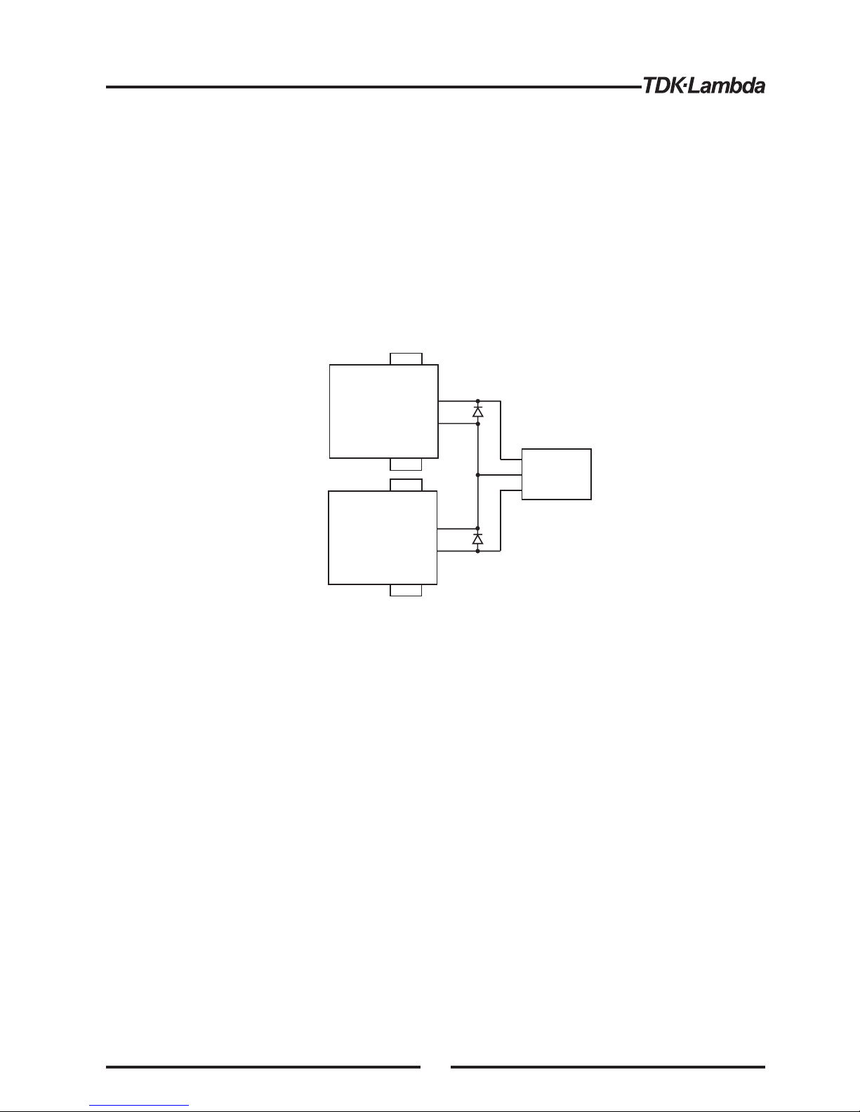
Fig.5-3: Series connection for positive/negative output voltages
3. Programming by external resistor:
1. Programming by external voltage:
Programming by external resistor is possible . Refer to
section 6-5 for details.
The analog programming circuits of this power supply
are referenced to the negative output potential.
Therefore, the circuits used to control each series
connected unit must be separated and floated from
each other.
The communication port is referenced to the IF_COM
which is isolated from the power supply output
potential. Therefore power supplies connected in
series can be chained using the Remote-In and
Remote-Out connectors. Refer to chapter 7 for details.
The Shut-Off and PS_OK circuits are referenced to the
isolated interface common, IF_COM (J1-2,3). The
IF_COM terminals of the units can be connected to
obtain a single control circuit for the power supplies
connected in series.
4. Programming via the Serial
Communication port (RS232/RS485):
4. Programming via the Serial
Communication port (RS232/RS485):
5.14.2 Series connection for positive and negative output voltage
In this mode, two units are configured as a positive and negative output. Set the current limit of each
power supply to the maximum that the load can handle without damage. It is recommended that
diodes be connected in parallel with each unit output to prevent reverse voltage during start-up or in
case one of the units shuts down. Each diode should be rated to at least the power supply rated
output voltage and output current. Refer to Fig.5-3 for this operating mode.
+S
+
-
-S
-LS
+LS
POWER
SUPPLY
+S
+
+
-
-
-S
-LS
+LS
POWER
SUPPLY
COM.
Remote programming in series operation for positive and negative output voltage
2. Using the SO function and PS_OK
signal :
3. Programming by external resistor :
Programming by external resistor is possible. Refer
to section 6.5 for details.
The communication port is referenced to the IF_COM
which is isolated from the power supply output
potential. Therefore power supplies connected in
series can be chained using the Remote-In and
Remote-Out connectors. Refer to chapter 7 for details.
LOAD
(*)
(*)
(*) Diodes are user supplied.
41
Page 50

5.15 PARALLEL OPERATION
Up to four units of the same VOLTAGEand CURRENT rating can be connected in parallel to provide
up to four times the output current capability. One of the units operates as a master and the
remaining units are slaves. The slave units are analog programmed by the master unit.
In remote digital operation, only the master unit can be programmed by the computer while the slave
units may be connected to the computer for voltage, current and status readback only.
There are two methods, basic and advanced, to configure multiple supplies for parallel operation.
Refer to Sec. 5.15.1 and to Sec. 5.15.2 for detailed explanation.
In this method, setting the units as Master and Slaves is made by the rear panel J1 connections and
the setup switch SW1. Each unit displays its own output current and voltage. To program the load
current, the Master unit should be programmed to the total load current divided by the number of
units in the system. Refer to the following procedure to configure multiple supplies for simple parallel
operation.
5.15.1 Basic parallel operation
5.15.2 Advanced parallel operation
In this method, multiple supplies can be configured to parallel operation as a single power supply.
The total load current and output voltage are displayed by the Master unit and can be readback
from the Master unit. The Slave units display only their operating status (On, Off or Fault
condition).
Refer to the following procedure to configure multiple supplies for Advanced parallel operation.
1. Basic configuration
Repeat steps 1 to 5 in Sec. 5.15.1 (Basic parallel operation).
1. Setting up the Master unit
2. Setting up the slave units
3. Setting Over Voltage protection
4. Setting Foldback protection
5. Connection to the load
Set the master unit output voltage to the desired voltage. Program the current limit to the
desired load current limit divided by the number of parallel units. During operation, the master
unit operates in CV mode, regulating the load voltage at the programmed output voltage.
Connect the sensing circuit to local or remote sensing as shown in Fig.5-4 or Fig.5-5.
-1.The output voltage of the slave units should be programmed 2%~5% higher than the output
voltage of the master unit to prevent interference with the master unit's control.
The current limit of each unit should be programmed to the desired load current limit
divided by the number of parallel units.
-2.Set the rear panel setup switch SW1 position 2 to it's up position.
-3.Set the rear panel setup switch SW1 position 3 in the same position as
SW1 position 4 of the master.
-4.Connect short between J1-8 and J1-12 (refer to Table 4-4.)
-5. Connect J1 terminal 10(IPGM) of the slave unit to J1 terminal 25(P) of the master unit.
-6. Connect J1 terminal 23(IPGM_RTN) of the slave unit to J1 terminal 12(COM) of the master
unit.
During operation the slave units operate as a controlled current source following the master
output current. It is recommended that the power system is designed so that each unit supplies
up to 95% of its current rating because of the imbalance which may be caused by cabling and
connections voltage drop.
The master unit OVP should be programmed to the desired OVP level. The OVP of the slave
units should be programmed to a higher value than the master OVP. When the master unit
shuts down, it programs the slave unit to zero output voltage. If a slave unit shuts down
(when its OVP is set lower than the master output voltage), only that unit would shut down
and the remaining slave units would supply all the load current.
Foldback protection if desired, may only be used with the master unit. When the master unit
shuts dow
n it programs the slave units to zero output voltage.
In parallel operation, power supplies can be connected in local or remote sensing. Refer to
Fig.5-4 and 5-5 for typical connections of parallel power supplies. The figures show
connection of two units, however the same connection method applies up to 4 units.
42
Page 51
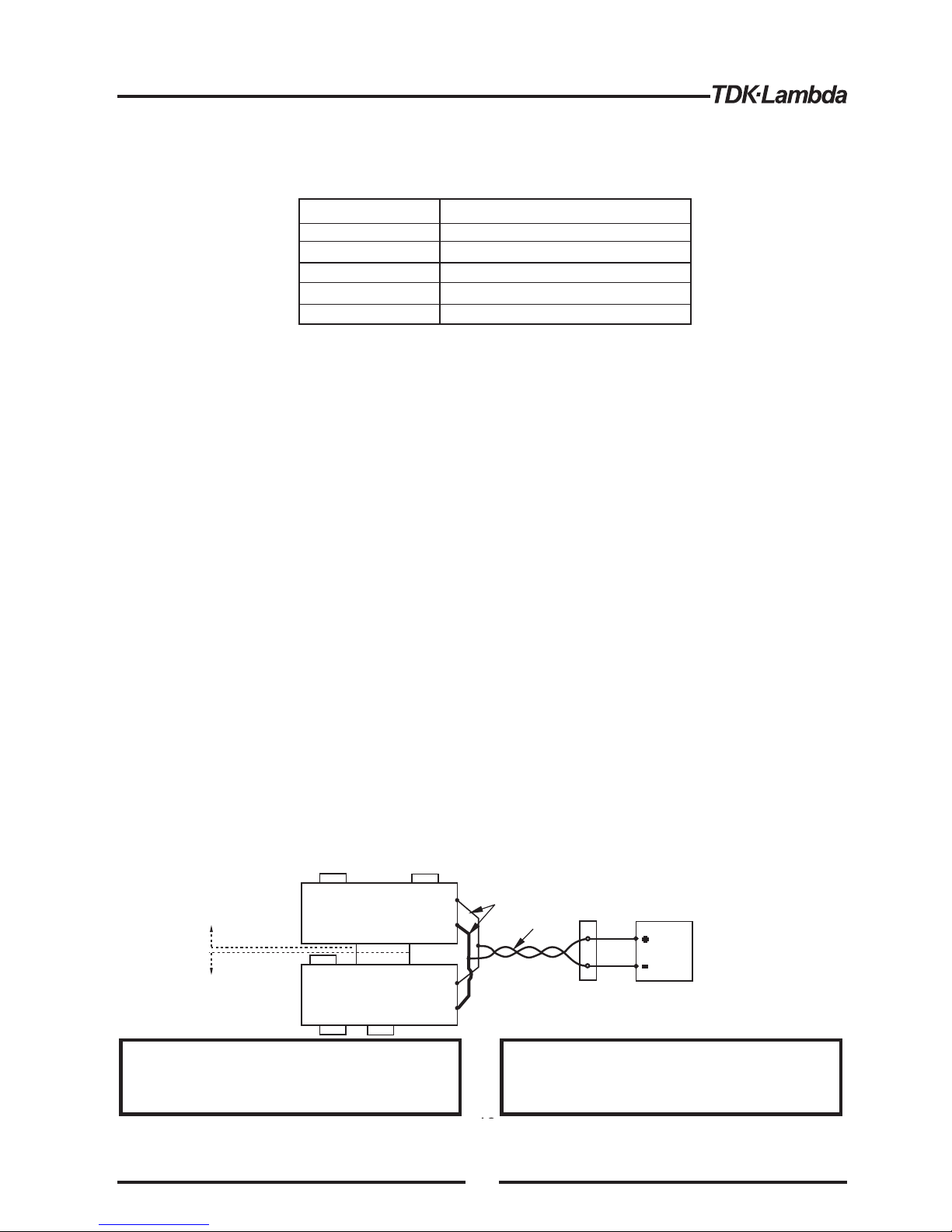
Make sure that the connection between -Vo terminals is
reliable to avoid disconnection during operatio n.
Disconnection may cause damage to the power supply.
+V
-V
+V
-V
+S
+LS
-S -LS
+S
+LS
-S -LS
MASTER
POWER SUPPLY
SLAVE#1
POWER SUPPLY
J1-25
J1-12 COM
J1-10
J1-23
P
IPGM
IPGM_RTN
To J1-23
SLAVE#2
POWER SUPPLY
To J1-10
SLAVE#2
POWER SUPPLY
Fig.5-4: Parallel connection
with local sensing
+
-
LOAD
As short as possible
Twisted
pair
J1-8
J1-12
CAUTION
VORSICHT
Stellen Sie sicher, dass die Verbindung zwischen den -V
Anschlussklemmen sich nicht während des Betriebs
lösen kann. Eine Unterbrechung kann die Netzteile
beschädigen.
2. Setting the units as Master or Slave
3. Master and Slave units default operation
4. CURRENT display accuracy
5. To release units from Slave mode
a) Depress and hold the FINE button for 3 seconds. The Master/Slave configuration will be
displayed on the Current Display. Rotate the CURRENT encoder to obtain the desired mode.
Refer to Table 5-4 for the CURRENT display and modes of operation.
b) When the desired configuration is obtained, depress and release the FINE button or wait
approx. 5 seconds.
a) When a unit is programmed to Slave mode it enters the Remote mode with Local Lockout. In
this mode, the front panel controls are disabled to prevent accidental setting change (refer to Sec.
7.2.7 for details).
b) The Slave units parameters will automatically set the following:
*Output voltage to approximate. 102% of rated output voltage.
*Programmed Current to zero.
*UVL to zero volts
*OVP to its maximum value
c) The Master and Slave modes are stored in the power supply EEPROM when the AC power is
Turned off. The system will return to the Master/Slave mode upon re-application of AC power.
In the advanced parallel mode, the total current is programmed and reported by the Master. In
this method, the CURRENT display accuracy is 2%+/- 1 count. In cases that higher accuracy is
required, it is recommended to use the basic parallel operation mode.
Slave units can be released using the following procedure:
a) Depress FINE button for 3 seconds. The Master/Slave configuration will be displayed on the
CURRENT display.
b) Select H1 mode using the CURRENT encoder.
c) Depress FINE button again or wait 5 seconds.
d) Turn the AC power Off to store the new setting.
e) After exiting from Slave operation the unit’s parameters will be set to:
CURRENT Display
H1
H2
H3
H4
S
Operating Mode
Single supply (default)
Master supply with 1 Slave supply
Master supply with 2 Slave supplies
Master supply with 3 Slave supplies
Slave supply
Table 5-4: Setting mode of operation
*AST On
*OUT On
*Foldback protection Off
*Programmed Voltage to zero *AST OFF
*Programmed Current to zero *OUT OFF
*UVL to zero volts *Foldback protection OFF
*OVP to its maximum value *Locked Front Panel
43
Page 52
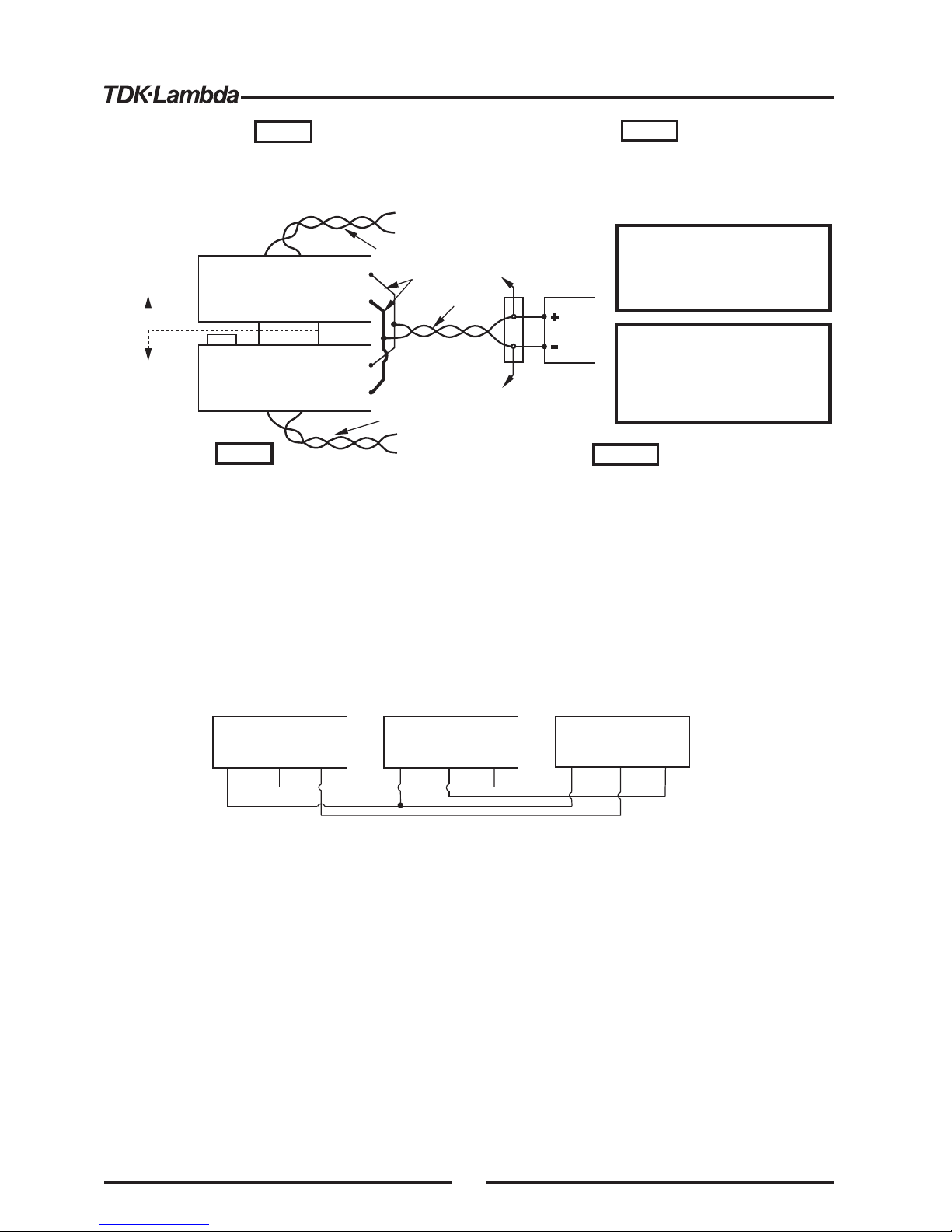
Fig.5-5: Parallel operation
wiith Remote sensing
With local sensing it is important to minimize the wire
length and resistance. Also the positive and negative
wire resistance should be close as possible to each
other to achieve current balance between power
supplies.
5.16 DAISY-CHAIN CONNECTION
It is possible to configure a multiple power supply system to shut down all the units when a fault
condition occurs in one of the units. When the fault is removed, the system recovers according to its
setting to Safe start mode or Automatic restart.
Setup switch SW1 position 5 should be set to its Down position to enable the Daisy-chain operation.
Other SW1 positions can be set according to the application requirements.
If a fault occurs in one of the units its PS_OK signal will be set to low level and the display will indicate
the fault. The other units will shut off and their display will indicate "SO”. When the fault condition is
removed, the units will recover to their last setting according to their Safe startor Auto-restart setting.
Fig.5-6 shows connection of three units, however the same connection method applies to systems
with a larger number of units.
Fig.5-6: Daisy-chain connection
POWER SUPPLY
#
1
J1-2,3
J1-16
J1-16
J1-16
J1-15
PS_OK
POWER SUPPLY
#
2
J1-2,3
J1-15
PS_OK
SO
POWER SUPPLY
#3
J1-2,3
J1-15
PS_OK
SO
SO
IF_COM
IF_COM
IF_COM
5.17 FRONT PANEL LOCKING
The front panel controls can be locked to protect from accidental power supply parameter change.
Press and hold PREV button to toggle between “Locked front panel” and “Unlocked front panel”.
The display will cycle between “LFP” and “UFP”. Releasing the PREV button while one of the
modes is displayed, selects that mode.
In this mode, the front panel controls are enable to program and monitor the power supply
parameters.
In this mode the following front panel controls are disabled:
- VOLTAGE and CURRENT encoders.
- FOLD button.
- OUT button.
The power supply will not respond to attempts to use these controls. The VOLT display will show
“LFP” to indicate that the front panel is locked.
OVP/UVLbutton is active to preview the OVPand UVL setting.
Use PREV button to preview the output voltage and current setting or to unlock the front panel.
5.17.1 Unlocked front panel
5.17.2 Locked front panel
MASTER
POWER SUPPLY
SLAVE#1
POWER SUPPLY
J1-25
J1-10
P
IPGM
J1-12 COM
J1-23
IPGM_RTN
Twisted
pair
+V
-V
+
V
-V
+S
-S
+
-
LOAD
As short as possible
Twisted
pair
+S-S
+S
-S
Twisted
pair
+S-S
+S
-S
J1-8
J1-12
To J1-10
SLAVE#2
POWER SUPPLY
To J1-23
SLAVE#2
POWER SUPPLY
Make sure that the connection
between -Vo terminals is reliable to
avoid disconnection during operation.
Disconnection may cause damage to
the power supply.
1.In parallel operation, the AC Supply should be applied
to the Master Unit first and then to the Slave unit.
2.The above sequence is not required if the units are
connected in daisy-chain.
CAUTION
VORSICHT
HINWEIS
HINWEISE
NOTE
NOTES
Bei lokalem Sensing ist es wichtig, Länge und
Widerstand der Ausgangsleitungen möglichst gering zu
halten. Zudem sollten die Leitungswiderstände der Plusund Minus- Leitungen möglichst identisch sein, um eine
gleichmä ige Lastaufteilung unter den Netzteilen zu
erreichen.
ß
Stell e n Sie siche r, dass d i e
Verb indu ng zwisch en den -V
Anchluss k l e m m e n s i c h n i c h t
während des Betriebs lösen kann.
Eine Unterbr echung kann die
Netzteile beschädigen.
1. Bei Parallelbetrieb sollte zunächst das Master-Netzteil mit dem Netz
verbunden werden, danach das Slave-Netzteil.
2. Bei "Daisy-chain" -Betrieb ist diese Abfolge nicht erforderlich.
44
Page 53

CHAPTER 6 REMOTE ANALOG PROGRAMMING
6.1 INTRODUCTION
The rear panel connector J1 allows the user to program the power supply output voltage and current
limit with an analog device. J1 also provides monitoring signals for output voltageand output current.
The programming range and monitoring signals range can be selected between 0-5V or 0-10V
using the setup switch SW1. When the power supply is in Remote Analog programming, the serial
communication port is active and can beused to read the power supply parameters.
COM (J1-12), VPGM_RTN (J1-22) and IPGM_ RTN
(J1-23) terminals of J1 are referenced to the -Vout
potential (-V). Do not connect these terminals to any
potential other than -Vout (-V), as it may damage the
power supply.
6.2 LOCAL /REMOTE ANALOG CONTROL
Contact 8 of J1 (Fig. 4-2, item 5) accepts TTL signal or Open-Short contact (referenced to J1-12) to
select between Local or Remote Analog programming of the output voltage and current limit.
In Local mode, theoutput voltage and current limit can be programmed via the front panel VOLTAGE
and CURRENT encoders or via the RS232/485 port. In Remote Analog mode, the output voltage
and current limit can be programmed by analog voltage or by programming resistors via J1 contacts
9 and 10 (refer to sec. 6.4 and 6.5). Refer to Table 6-1 for Local/Remote Analog control (J1-8)
function and Setup switch SW1-1, 2 setting.
6.3 LOCAL/REMOTE ANALOG INDICATION
Contact 21 of J1 (Fig. 4-2, item 5) is an open collector output that indicates if the power supply is in
Local mode or in Remote Analog mode. To use this output, connect a pull-up resistor to a voltage
source of 30Vdc maximum. Choose the pull-up resistor so that the sink current will be less than 5mA
when the output is in low state. Refer to Table 6-2 for J1-21 function.
Table 6-1: Local/Remote Analog control function
Table 6-2: Local/Remote Analog indication
SW1-1,2 setting
Down (default)
Up
J1-8 function
Output voltage/
Current setting
No effect
"0" or Short
"1" or Open
Local
Remote Analog
Local
TTL "0" or short
TTL "1" or open
SW1-1
SW1-2
J1-8
J1-21 signal
Down
Down
Up
Up
Down or Up
Down
Up
Down
Up
Down or Up
Open
0~0.6V
0~0.6V
0~0.6V
Open
CAUTION
VORSICHT
Am J -Verbinder sind die Anschlüsse COM (J - 2),
VPGM_RTN (J -22) und PGM_RTN (J -23) sind mit
dem -Vout-Potential (-V) verbunden. Verbinden Sie
diese Anschlüsse nie mit einem anderen Potential als
-Vout (-V), da dies das Netzteil beschädigen könnte.
1 1 1
1 I 1
45
Page 54
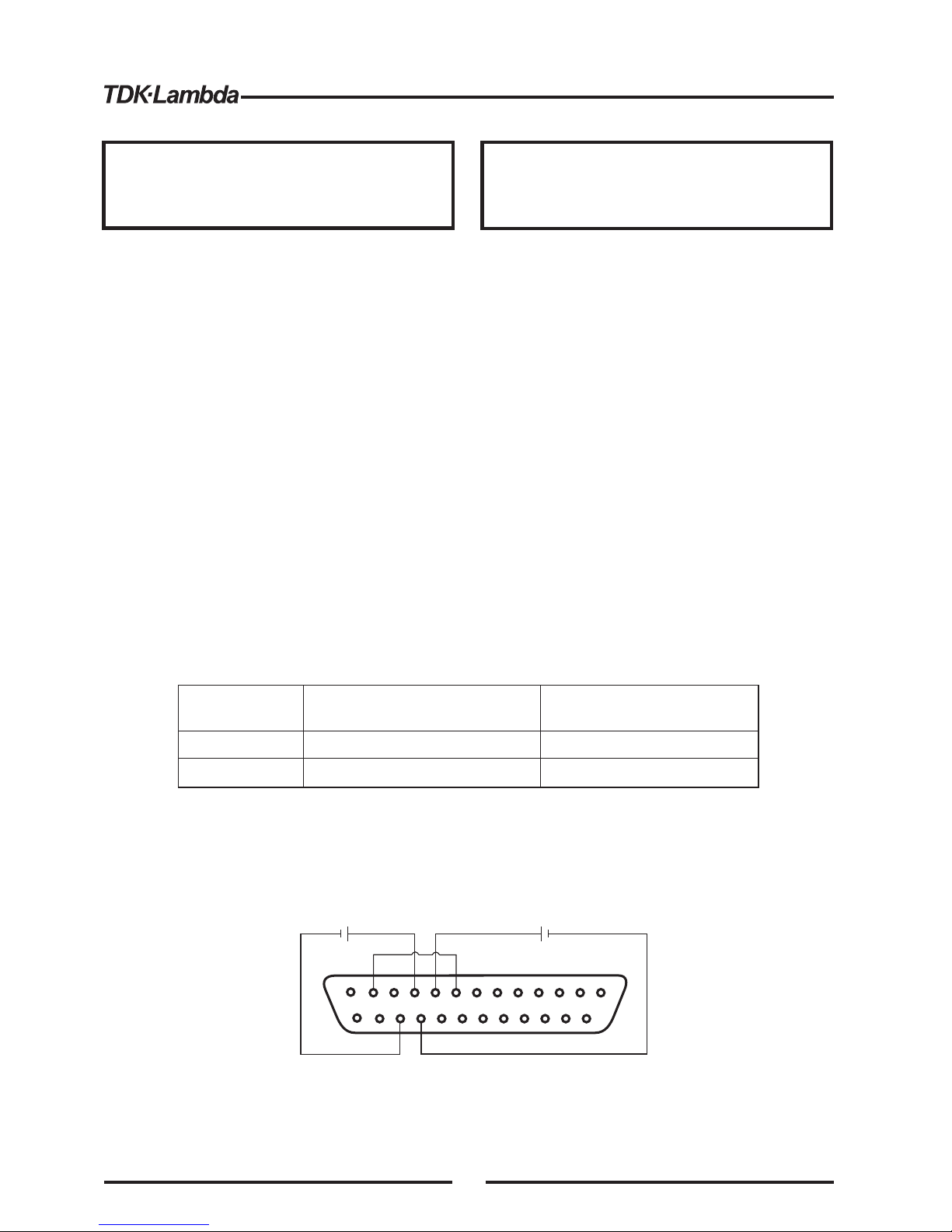
6.4 REMOTE VOLTAGE PROGRAMMING OF OUTPUT VOLTAGE AND CURRENT LIMIT
SW1-3 setting
UP
DOWN
Output Voltage programming
VPGM (J1-9)
0-10V
0-5V
Current limit programming
IPGM (J1-10)
0-10V
0-5V
Table 6-3: SW1-3 setting and programming range
1
14
13
25
10
12
8
9
23
22
+
-
+
-
CURRENT LIMIT
PROGRAMMING
OUTPUT VOLTAGE
PROGRAMMING
J1 connector, rear panel view
Fig.6-1: Remote voltage programming connection
Perform the following procedure to set the power supply to Remote Voltage programming :
1. Turn the power supply AC On/Off switch to Off.
2. Set setup switch SW1-1 to its UP position for output voltage external programming and
SW1-2 to its UP position for Output Current limit external programming.
3. Set SW1 position 3 to select programming voltage range according to Table 6-3.
4. Ensure that SW1 positions 7 and 8 are at their Down (default) position.
5. Connect a short between J1-8 and J1-12 (refer to Table 4-4).
6. Connect the programming source to the mating plug of J1 as shown in Fig.6-1. Observe
correct polarity for the voltage source.
7. Set the programming sources to the desired levels and turn the power supply ON. Adjust the
programming sources to change the power supply output.
1.SW1 positions 4,5,6 and 9 are not required for
remote programming. Their setting can be
determined according the application.
2.The control circuits allow the user to set the output
voltage and current limit up to 5% over
the model-rated maximum value. The power supply
will operate within the extended range,
however it is not recommended to operate the power
supply over its voltage and current
rating and performance is not guaranteed.
Hinweise:
Notes:
To maintain the isolation of power supply and prevent
ground loops, use an isolated programming source
when operating the power supply via remote analog
programming at J1 connector.
VORSICHT
CAUTION
Wenn Sie das Netzteil mit analogen Spannungen1über
den J - Verbinder ansteuern, verwenden Sie eine
isolierte Signalquelle, um Erdschleifen zu vermeiden
und die lsolation des Netzteils zu erhalten.
1 1
1
.Die Schalter 4, 5, 6 und 9 von SW sind für die
Fernprogrammierung nicht relevent. lhre Einstellung
kann der Applikation entsprechend erfolgen.
2.Die Bedienelemente des Netzteiles erlauben es dem
Anwender, Ausgangsspannung und -strom auf bis zu
05% der Nennhöchstwertes einzustellen. Das Netzteil
arbeitet in diesem erweiterten Bereich, jedoch sollte das
Netzteil im normalen Einsatz nicht über die Nennwerte
hinaus betrieben werden. Die Spezifikationen der
Ausgangsparameter werden nur innerhalb des
Nennbereiches für Ausgangsspannung und -strom
garantiert.
46
Page 55
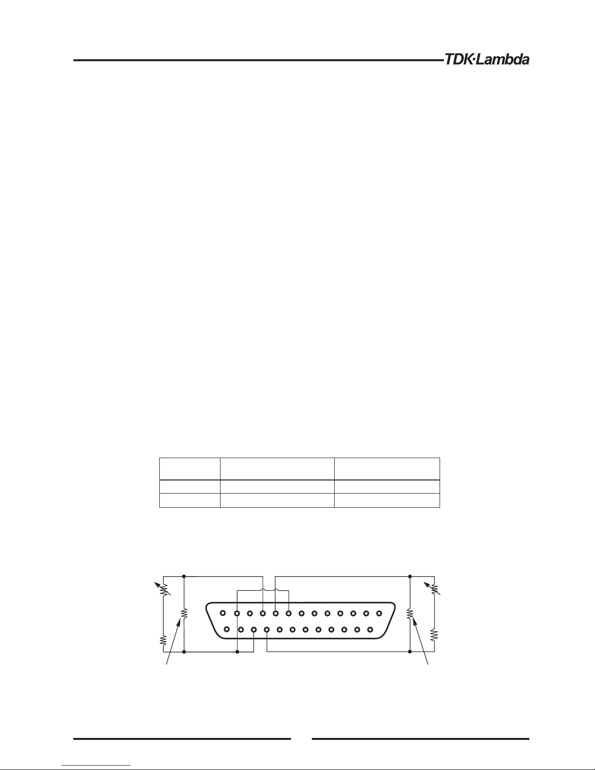
6.5 RESISTIVE PROGRAMMING OF OUTPUT VOLTAGE AND CURRENT LIMIT
For resistive programming, internal current sources, for output voltage and/or output current control,
supply 1mA current through external programming resistors connected between J1-9 & 22 and J1-10
& 23. The voltage across the programming resistors is used as a programming voltage for the power
supply. Resistance of 0~5Kohm or 0~10Kohm can be selected to program the output voltage and
current limit from zero to full scale.
A variable resistor can control the output over its entire range, or a combination of variable resistor
and series/parallel resistors can control the output over restricted portion of its range.
Perform the following procedure to set the power supply to Resistive programming:
1. Turn the AC On/Off switch to Off.
2. Set setup switch SW1-1 to its UP position for output voltage external programming and
SW1-2 to its UP position for Output Current limit external programming.
3. Set SW1 position 3 to select programming resistor range according to Table 6-4.
4. Set SW1-7 to its UP position for output voltage resistive programming and
SW1-8 to its UP position for Output Current limit resistive programming.
5. Connect a short between J1-8, J1-12 and J1-23 (refer to Table 4-4).
6. Connect the programming resistors to the mating plug of J1 as shown in Fig.6-2.
7. Set the programming resistors to the desired resistance and turn the power supply ON.
Adjust the resistors to change the power supply output.
1. SW1 positions 4, 5, 6 and 9 are not required for remote programming. Their setting can be
determined according to the application requirements.
2. The control circuits allow the user to set the output voltage and current limit up to 5% over
the model-rated maximum value. The power supply will operate within the extended range,
however it is not recommended to operate the power supply over its voltage and current
rating and performance is not guaranteed.
3. To maintain the temperature stability specification of the power supply, the resistors used for
programming should be stable and low noise resistors, with temperature coefficient of less
than 50ppm.
4. When resistive programming is used, front panel and computer control (via serial communication
port) of output voltage and current are disabled.
NOTES:
SW1-3 setting
UP
DOWN
Output Voltage programming
VPGM (J1-9)
0-10Kohm
0-5Kohm
Current limit programming
IPGM (J1-10)
0-10Kohm
0-5Kohm
Table 6-4: SW1-3 setting and programming range
1
14
13
25
10 9
23
22
CURRENT LIMIT
PROGRAMMING
OUTPUT VOLTAGE
PROGRAMMING
J1 connector, rear panel view
Fig.6-2: Remote resistive programming
PROGRAMMING
RESISTOR
PROGRAMMING
RESISTOR
OPTIONAL SETS
LOWER LIMIT
OPTIONAL SETS
LOWER LIMIT
OPTIONAL SETS
UPPER LIMIT
OPTIONAL SETS
UPPER LIMIT
12
8
47
Page 56
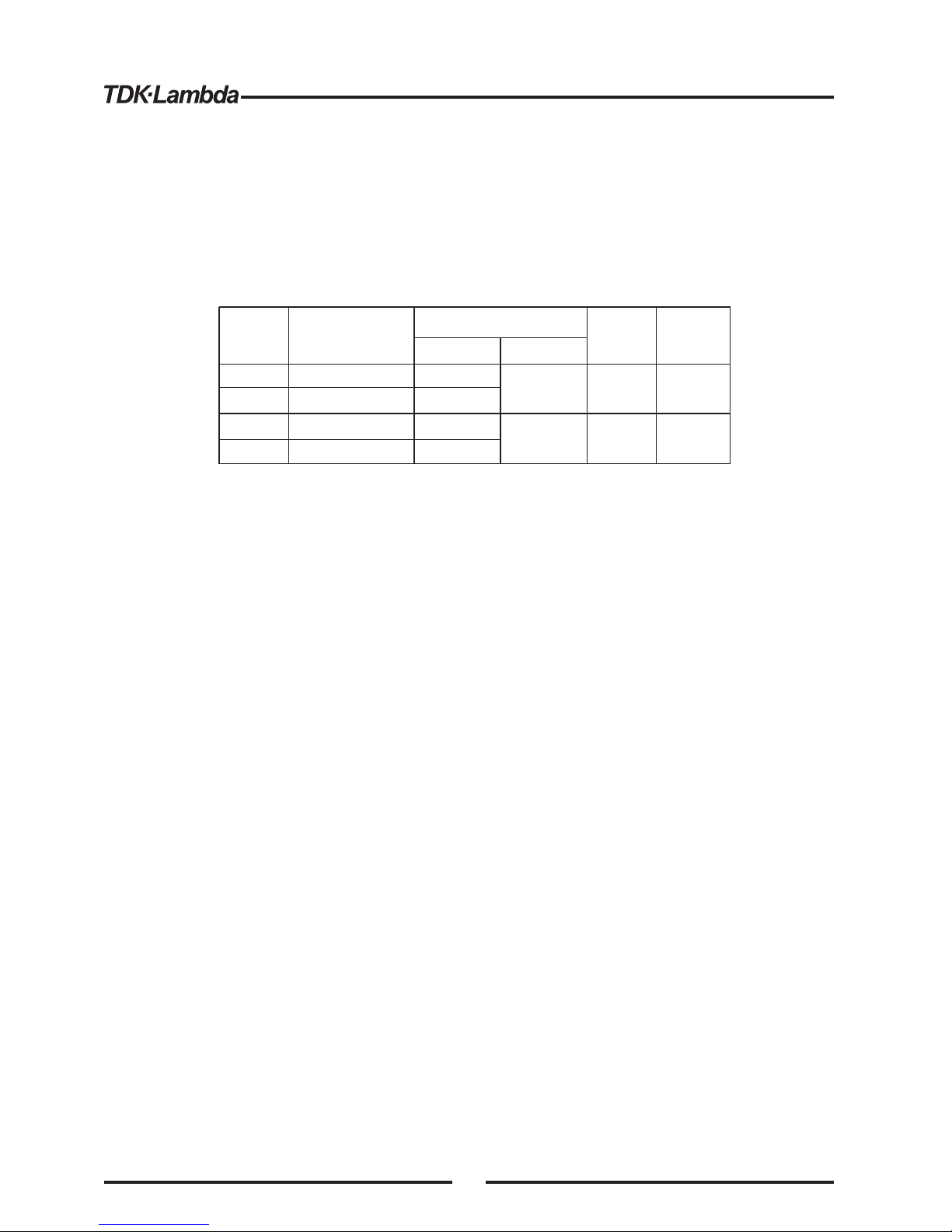
6.6 REMOTE MONITORING OF OUTPUT VOLTAGE AND CURRENT
The J1 connector, located on the rear panel provides analog signals for monitoring the output
voltage and output current. Selection of the voltage range between 0-5V or 0-10V is made by
setup switch SW1-4. The monitoring signals represent 0 to 100% of the power supply output
voltage and output current.The monitor outputs have 500 ohm series output resistance. Ensure
that the sensing circuit has an input resistance of greater than 500 Kohm or accuracy will be
reduced.
Refer to Table 6-5 for required J1 connection, SW1-4 setting and monitoring voltage range.
Signal
name
VMON
IMON
VMON
IMON
Signal function
Vout monitor
Iout monitor
Vout monitor
Iout monitor
Signal (+)
J1-11
J1-24
J1-11
J1-24
J1-12
J1-12
0-5V
0-10V
Down
Up
Range
SW1-4
Return (-)
J1 connection
Table 6-5 Monitoring signals setting
FCC requirements for radiated emissions, use
shielded cable for the analog control signals. In case of
using unshielded ca ble, attach an EMI ferrite
suppressor to the cable, as close as possible to the
power supply.
1.Radiated emissions, FCC requirements:
Notes:
2. Front panel encoders operation:
3. Front panel PREV button:
4. Communication:
In Remote analog mode the output voltage and
current can’t be set by the VOLTAGE and CURRENT
encoders.
Use PREV button to display the output voltage and
current setting defined by the en coders or
communication.
In Remote analog mode, power supply parameters
can be programmed and readback via the
communication port except output voltage and current
setting.
48
Page 57

CHAPTER 7 RS232 & RS485 REMOTE CONTROL
7.1 INTRODUCTION
7.2 CONFIGURATION
This chapter describes the operation of the Genesys 2400W power supplies via the serial
communication port. Details of the initial set-up, operation via RS232 or RS485, the command set
and the communication protocol are described in this chapter.
The power supply is shipped with the following setting:
TM
7.2.1 Default setting
-Address:
-Baud-rate:
-RS232/485:
-Vout setting:
-Iout setting:
-Master/Slave
6
9600
RS232
0
Maximum
H1 (Master)
-Output:
-Start up mode:
-OVP:
-UVL:
-Foldback:
-Front panel:
Off
Safe start
Maximum
0
Off
Unlocked (UFP)
7.2.2 Address setting
7.2.3 RS232 or RS485 selection
7.2.4 Baud rate setting
7.2.5 Setting the unit into Remote or Local mode
The power supply address can be set to any address between 0 and 30. Follow the instructions
described below to set the address.
1. If the unit is in Remote mode (front panel REM/LOC LED illuminates), press REM/LOC
button to put the unit into Local mode.
2. Press and hold for approximately 3sec. the REM/LOC button. The VOLTAGE display will
indicate the communication port address.
3. Using the VOLTAGE adjust encoder, select the address.
To preview the address at any time, press and hold the REM/LOC button for approx. 3sec. The
VOLTAGE display will indicate the power supply address.
To select between RS232 or RS485 set the rear panel setup switch SW1-6 position to:
- Down for RS232
- Up for RS485
Five optional rates are possible: 1200, 2400, 4800, 9600 and 19200. To select the desired rate,
the following steps should be taken:
1. If the unit is in Remote mode (front panel REM/LOC LED illuminates), press REM/LOC
button to put the unit into Local mode.
2. Press and hold for approx. 3sec. the REM/LOC button. The CURRENT display will show
the communication port Baud Rate.
3. Using the CURRENT adjust encoder, select the desired Baud Rate.
1. The unit will be
put into Remote mode only via serial communication command.
Commands that will put the unit into Remote mode are:
RST PV n
OUT n PC n
RMT n
(for n values see Tables 7-3, 7-4, 7-5 and 7-6)
49
Page 58
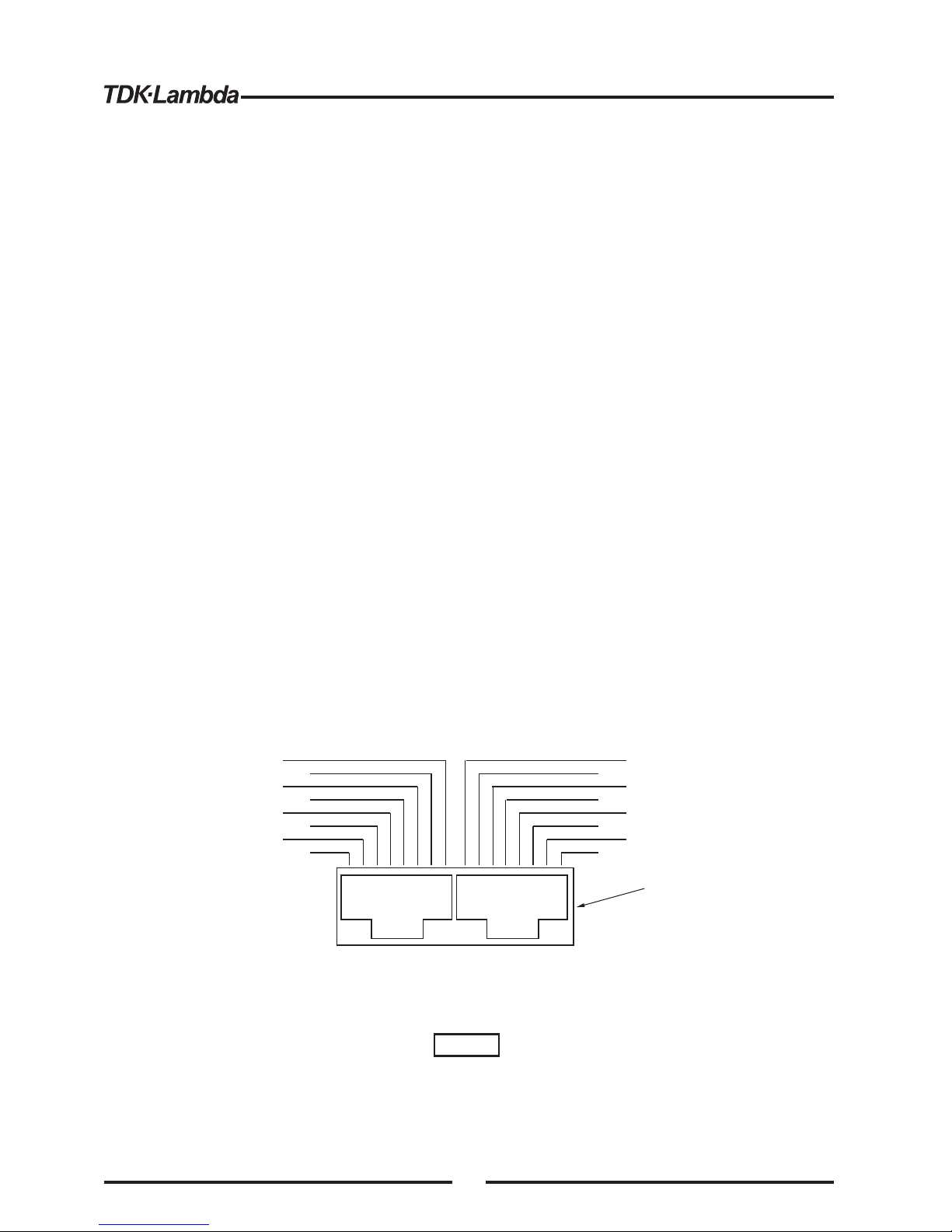
2. There are two Remote modes:
1. Remote:
2. Local Lockout:
In this mode, return to local can be made by the front panel REM/LOC or via
serial port command RMT 0. Set the unit into Remote mode via serial port
RMT 1 command.
In this mode the unit can be returned to Remote mode via the serial port
RMT 1 command or by turning off the AC power until the display turns off
and then turn it to on again. In Local Lockout mode, the front panel
REM/LOC button is not active. Set the unit into Local Lockout mode via
serial port RMT 2 command.
7.2.6 RS232/485 port in Local mode
7.2.7 Front panel in Remote mode
When the power supply is in local mode, it can receive queries or commands. If a query is received,
the power supply will reply and remain in Local mode. If a command that affects the output is
received, the power supply will perform the command and change to Remote mode.
Serial commands may be sent to set the status registers and read them while the unit is in Local
mode. If the Enable registers are set (refer to section 7.8) the power supply will transmit SRQ’s while
in Local.
Front panel control in Remote mode is disabled except for:
1. PREV: use to preview the Voltage and Current limit setting.
2. OVP/UVL: use to preview the OVP/UVLsetting.
3. LOC/REM: use to set the unit into Local mode.
In Local Lockout mode, only PREV and OVP/UVLare active.
The RS232/485 interface is accessible through the rear panel RS232/485 IN and RS485 OUT
connectors. The connectors are 8 contact RJ-45. The IN and OUT connectors are used to connect
power supplies in a RS232 or RS485 chain to a controller. Refer to Fig.7-1 for IN/OUT connectors
7.3 REAR PANEL RS232/485 CONNECTOR
Tx and Rx are used for RS232 communication. Txd +/- and Rxd +/- are used for RS485
communication. Refer to RS232 and RS485 cables description for connection details.
NOTE
NC
NC
RX
NC
NC
TXD
RXD
TXD
RXD
RXD
TXD
RXD
TXD
SG
SG
-
-
-
-
+
+
+
+
TX
OUT
IN
Fig.7-1: J3 rear panel IN/OUT connectors pinout
8 7 6 5 4 3 2 1
8 7 6 5 4 3 2 1
Shield
(connector enclosure)
50
Page 59
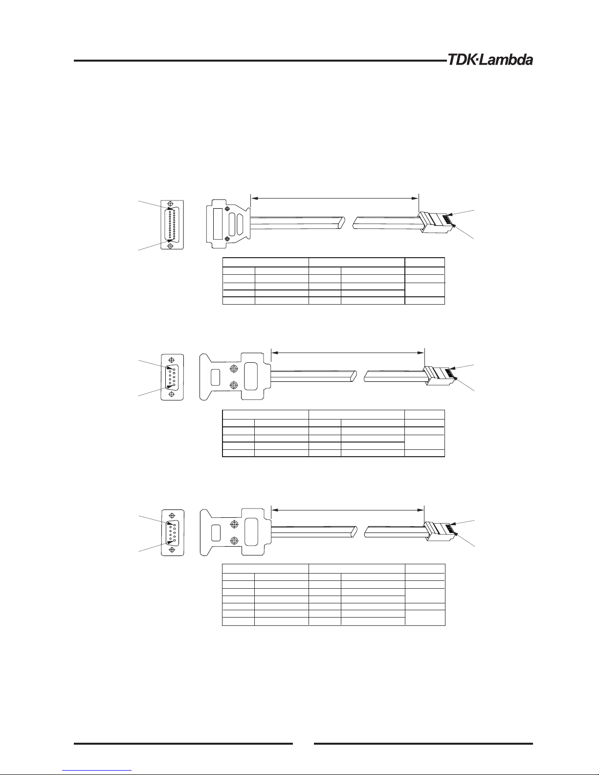
7.4 CONNECTING POWER SUPPLIES TO RS232 OR RS485 BUS
7.4.1 Single power supply
1. Select the desired interface RS232 or RS485 using rear panel setup switch SW1-6 (section 4-4).
- RS232: Down position
- RS485: Up position
2. Connect rear panel IN connector to the controller RS232 or RS485 port using a suitable shielded
cable. Refer to Figures 7-2, 7-3 and 7-4 for available RS232 and RS485 cables.
2
3
7
1
8
7
1
HOUSING
PIN NO.
PIN NO.NAME
NAME
SHIELD
TX
RX
SG
SHIELD
RX
TX
SG
DB-25 CONNECTOR
8 PIN CONNECTOR
REMARKS
TWISTED
PAIR
8
1
13
1
2
3
5
7
8
1
PIN NO.
HOUSING
HOUSING
PIN NO.NAME
NAME
SHIELD
RX
TX
SG
SHIELD
TX
RX
SG
DB-9 CONNECTOR
8 PIN CONNECTOR
REMARKS
TWISTED
PAIR
8
1
5
1
9
8
1
5
4
6
3
1
5
4
PIN NO.
HOUSING
HOUSING
PIN NO.NAME
NAME
TWISTED
PAIR
TWISTED
PAIR
SHIELD
TXD
TXD
SG
RXD
RXD
SHIELD
RXD
RXD
SG
TXD
TXD
DB-9 CONNECTOR
8 PIN CONNECTOR
REMARKS
-
+
+
+
+
-
-
-
8
1
5
1
Fig.7-2: RS232 cable with DB25 connector (P/N: GEN/232-25)
Fig.7-3: RS232 cable with DB9 connector (P/N: GEN/232-9)
Fig.7-4: RS485 cable with DB9 connector (P/N: GEN/485-9)
L=2m typ.
L=2m typ.
L=2m typ.
Socket
Socket
Socket
51
Page 60
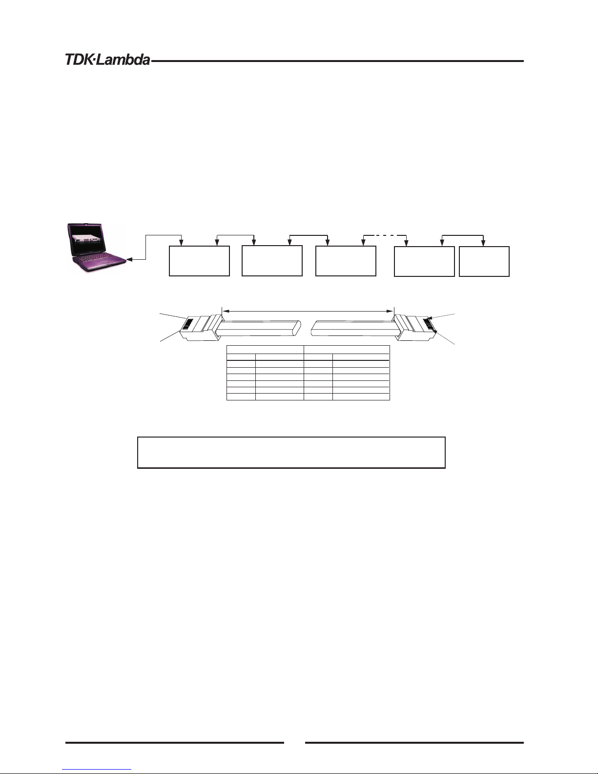
7.4.2 Multi power supply connection to RS232 or RS485 bus
Daisy-chain up to 31 units can be connected to RS232 or RS485 bus. The first unit connects to the
controller via RS232 or RS485 and the other units are connected with RS485 bus, the user must set
all slave supplies to a unique address. No two supplies may have the same address.
1. First unit connection: Refer to section 7.4.1 for connecting the first unit to the controller.
2. Other units connection: The other units on the bus are connected via their RS485 interface.
Refer to fig.7-5 for typical connection.
- Set rear panel setup switch SW1-6 to it's UP position
- Using the Linking cable supplied with each unit (refer to Fig.7-6), connect each unit OUT
connector to the next unit IN connector.
* I
120 ohm resistive termination at the last unit’s RS485 OUT connector.
120 W between TXD and TXD
+ -
t is recommended when using several power supplies in Daisy-chain system to connect a
120 W between RXD and RXD
+ -
7.5 COMMUNICATION INTERFACE PROTOCOL
7.5.1 Dataformat
7.5.2 Addressing
7.5.3 End of Message
7.5.4 Command Repeat
7.5.5 Checksum
7.5.6 Acknowledge
Serial data format is 8 bit, one start bit and one stop bit. No paritybit.
The Address is sent separately from the command.
It is recommended to add a 100 msec software delay between query orsent commandto
next unit addressing.
Refer to section 7.7.3 for details.
The end of message is the Carriage Return character (ASCII 13). The power supply ignores the Line
Feed (ASCII 10) character.
The backslash character “\” will cause the last command to be repeated.
The user may optionally add a checksum to the end of the command. The checksum is "$" followed by
two hex characters. If a command or a query has checksum, the response will also have one. There is no
CR between the command string and the "$" sign.
Example: STT?$3A
STAT?$7B
The power supply acknowledges received commands by returning "OK"message. Ifan erroris detected,
the power supply will return an error message. The rules of checksum applyalso tothe acknowledge.
IN
OUT
POWER SUPPLY
#1
IN
OUT
POWER SUPPLY
#2
IN
OUT
POWER SUPPLY
#3
RS232/485
RS485
RS485
RS485
IN
OUT
RS485
120 OHM
TERMINATION
POWER SUPPLY
#31
RS485
Fig7-5: Multi power supplies RS232/485 connection
1
6
3
5
4
1
6
3
5
4
PIN NO.
HOUSING
HOUSING
PIN NO.NAME
NAME
SHIELD
SG
TXD
TXD
RXD
RXD
SHIELD
SG
RXD
RXD
TXD
TXD
8 PIN CONNECTOR (IN)
8 PIN CONNECTOR (OUT)
-
+
+
+
+
-
-
-
Serial link cable with RJ-45 shielded connectors (P/N: GEN/RJ45)
Fig.7-6:
8
1
1
8
L=0.5m typ.
The address (ADR n) command must return an “OK” response before
any other commands are accepted.
NOTE
52
Page 61

7.5.7 Error message
7.5.8 Backspace
If an error is detected in a command or query, the power supply will respond with an error
message. Refer to section 7.6 for details.
The backspace character (ASCII 8) clears the last character sent to the power supply.
The power supply will return error messages for illegal commands and illegal programming
parameters. Refer to Table 7-1 for programming error messages and Table 7-2 for commands
error messages.
Table 7-1: Programming error messages
7.6 ERROR MESSAGES
Table 7-2: Commands error messages
7.7 COMMAND SET DESCRIPTION
7.7.1 General guides
7.7.2 Command set categories
1. Any command or argument may be in capital letters or small letters.
2. In commands with an argument, a space must be between the command and the argument.
3. For any command that sets a numeric value, the value may be up to 12 characters long.
4. Carriage Return: If the CR character (ASCII 13) is received by itself, the power supply will
respond with "OK" and CR.
The Genesys 2400W series command set is divided into four categories as follows:
1. Initialization control
2. ID control
3. Output control
4. Statuscontrol
TM
E01
E02
E04
E06
E07
Description
Returned when program voltage (PV) is programmed above acceptablerange.
Example: PV value is above '105% of supply rating' or 'PV above 95% of OVP setting'.
Returned when programming output voltage below UVLsetting.
Returned when OVP is programmed below acceptablerange.
Example:OVP value is less than '5% of supply voltagerating' plus 'voltage setting'.
Returned when UVLvalue is programmed above the programmed output voltage.
Returned when programming the Output to ON during a fault shut down.
Error
Code
C01
C02
C03
C04
C05
Description
Illegal command or query
Missing parameter
Illegal parameter
Checksum error
Setting out of range
Error
Code
53
Page 62
7.7.3 Initialization control commands
ADR is followed by address which can be 0 to 30 and is used to access the
power supply .
Clear status. Sets FEVE and SEVE registers to zero (refer to section 7-8).
Reset command. Brings the power supply to a safe and known state:
Output voltage: zero, Remote: non-latched remote,
Output current: zero, Auto-start: Off,
Output: Off, OVP: maximum,
FOLD: Off, UVL: zero
The conditional registers (FLT and STAT) are updated, the other registers are
not changed.
Command
Sets the power supply to local or remote mode:
1. RMT 0 or RMT LOC, sets the power supply into Local mode.
2. RMT 1 or RMT REM, sets the unit into remote mode.
3. RMT 2 or RMT LLO, sets the unit into Local Lockout mode (latched remote mode).
#
Description
1
ADR n
2
CLS
3
RST
4
RMT
Returns the Remote mode setting:
1. "LOC"- The unit is in Local mode.
2. "REM"- The unit is in Remote mode.
3. "LLO"- The unit is in Local Lockout (latched remote) mode.
Returns MD MODE OPTION Status. 1 indicates installed and 0 indicates not
installed.
Repeat last command. If \<CR> is received, the power supply will repeat the
last command.
5
6
7
RMT?
MDAV?
\
7.7.5 Output control commands
7.7.4 ID control commands
Command
#
Description
Returns the power supply model identification as an string
Returns the software version as an ASCII string.
Returns the unit serial number. Up to 12 characters.
Returns date of last test. Date format: yyyy/mm/dd
ASCII
: LAMBDA, GENX-Y
1
2
3
4
IDN?
REV?
SN?
DATE?
Command
#
Description
Sets the output voltage value in Volts. The range of voltage value is described in
Table7-3. The maximum number of characters is 12. See the following examples
for PV n format: PV 12, PV 012, PV 12.0, PV 012.00, etc...
Reads the output voltage setting. Returns the string "n" where "n" is the exact
string sent in the PV n command. When in Local mode, returns the PREVIEW
(front panel) settings in a 5 digits string.
Reads the actual output voltage. Return 5 digits string.
Example: 60V supply sends 01.150, 15.012, 50.000, etc...
1
PV n
2
PV?
3
MV?
Reads the output current setting. Returns the string "n" where "n" is the exact
string sent in the PC n command. When in Local mode, returns the
PREVIEW (front panel) settings in a 5 digits string.
4
PC n
(See Note 1)
5
PC?
Sets the output current value in Amperes. The range of current values is
described in Table 7-4. The maximum number of characters is 12. See the
following examples for PC n format: PC 10, PC 10.0, PC 010.00, etc...
54
Page 63

7.7.5 Output control commands-cont
#
Command
Description
Sets the Foldback protection to ON or OFF.
FLD 1 (or FOLD ON) - Arms the Foldback protection.
FLD 0 (or FOLD OFF)- Cancels the Foldback protection.
When the Foldback protection has been activated, OUT 1 command will release the
protection and re-arm it, while FLD 0 will cancel the protection.
Returns the Foldback protection status string:
“ON”- Foldback is armed, “OFF”- Foldback is canceled.
Add (nn x 0.1) seconds to the Fold Back Delay. This delay is in addition to the standard
delay. The range of nn is 0 to 255. The value is stored in eprom at AC power down and
recovered at AC power up.
Supply returns the value of the added Fold Back Delay.
Reset the added Fold Back Delay to zero.
Returns the output On/Off status string.
ON- output on. OFF- output off.
Display Voltage and Current data. Data will be returned as a string of ASCII characters. A
comma will separate the different fields. The fields, in order, are: Measured Voltage,
Programmed Voltage, Measured Current, Programmed Current, Over Voltage Set point
and Under Voltage Set Point.
Example: 5.9999, 6.0000, 010.02, 010.00, 7.500, 0.000
10
FLD n
11
12
13
14
FLD?
FBD nn
FBD?
FBDRST
9
8
OUT?
Sets the OVP level. The OVP setting range is given in Table 7-5. The number of characters
after OVP is up to 12.
The minimum setting level is approx. 105% of the set output voltage, or the value in Table
7-6, whichever is higher. The maximum setting level is shown in Table 5-1. Attempting to
program the OVP below this level will result in execution error response (”E04”). The OVP
setting stays unchanged.
15
OVP n
Returns the power supply operation mode. When the power supply is On (OUT 1) it will
return “CV” or “CC”. When the power supply is OFF (OUT 0) it will return “OFF”.
Returns the Master/Slave setting. Master: n = 1, 2, 3, or 4 Slave: n = 0
Saves present settings.The settings are the same as power-down last settings.
These settings are erased when the supply power is switched off and the new “last settings”
are saved.
Sets Under Voltage Limit. Value of “n” may be equal to PV setting, but returns “E06” if
higher. Refer to Table 7-6 for UVL programming range.
Sets OVP level to the maximum level. Refer to Table 7-5.
Returns the setting “n” where “n” is the exact string in the user’s “UVL n”. When in Local
mode, returns the last setting from the front panel in a 4 digit string.
Returns the setting “n” where “n” is the exact string in the user’s “OVP n”. When in Local
mode, returns the last setting from the front panel in a 4 digit string.
Returns the string auto-restart mode status.
Recalls last settings. Settings are from the last power-down or from the last “SAV”
command.
16
OVP?
17
OVM
18
UVL n
19
UVL?
21
AST?
22
SAV
23
RCL
24
25
MODE?
MS?
Sets the auto-restart mode to ON or OFF.
AST 1 (or AST ON)- Auto restart on.
AST 0 (or AST OFF)- Auto restart off.
20
AST n
Reads the actual output current. Returns 5 digits string.
Example: 200A supply sends 000.50, 110.12, 200.00, etc...
Turns the output to ON or OFF. Recover from Safe-Start, OVP or FLD fault.
OUT 1 (or OUT ON)-Turn On.
6
MC?
(See Note 2)
7
OUT n
DVC?
55
Page 64
Table 7-3: Voltage programming range
Model
Rated Output Voltage (V)
Minimum
(V)
Maximum
(V)
8
10
16
20
30
40
60
80
100
150
300
600
0.000
00.000
00.000
00.000
00.000
00.000
00.000
00.00
000.00
000.00
000.00
000.00
8.000
10.000
16.000
20.000
30.000
40.000
60.000
80.00
100.00
150.00
300.00
600.00
NOTE:
The power supply can accept values higher by 5% than
the table values, however it is not recommended to
program the power supply over the rated values.
7.7.6 Global output commands
1. General
All supplies, even if not the currently addressed supply, receiving a global command will execute
the command. No response to the PC issuing the command will be returned to the PC. The PC
issuing the command will be responsible to delay and any other communications until the
command is execute. 200 Ms minimum is the suggested delay.
If the command contains an error, out of range values for example, no error report will be sent to
the issuing PC.
Reset. Brings the Power Supply to a safe and known state:
Output voltage: 0V, output current: 0A, OUT: Off, Remote: RMT 1’
AST: Off OVP:Max, UVL:0.
The conditional register (FLT and STAT) are updated. Other registers are not changed.
Non-Latching faults (FB, OVP, SO) are cleared, OUT fault stays.
Sets the output voltage value in volts. The range of voltage values is shown in Table 7-3.
‘n’ may be up to 12 char plus dec. pt
Program the output current value in amperes. The range of current values is shown in
Table 7-4. ‘n’ may be up to 12 char plus dec. pt
Turns the output to ON or OFF:
“GOUT 1/ON” = turn on
“GOUT 0/OFF”= turn off, clears CV and CC bits in the Status Condition (STAT)
OUT ON will respond with “E07’ if the output cannot be turned on because of a latching
fault (OTP< AC, ENA, SO) shutdown.
1.
GRST
2.
3.
4.
GPV n
GPC n
GOUT
Save present settings. Same settings as power-down last settings listed in Error!
Reference source not found. Except the address and Baud rate are not saved
Saves to the RAM. These settings are erased when the supply power is switched off and
the new ‘last settings’ are saved.
5.
GSAV
Recall last settings. Settings are from last power-down or from last ‘SAV’ or ‘GSAV’
command. Address and Baud rate are not recalled so communication is not interruped.
6.
GRCL
NOTES:
1. In Advanced parallel mode (refer to Sec. 5.15.2), “n” is the total system current.
2. In Advanced parallel mode, “MC?” returns the Master unit current multiplied by the number of
slave units+1.
56
Page 65
NOTE:
The power supply can accept values higher by 5% than thetable values, however it
is not recommended to program the power supply over the rated values.
7.7.7 Status control commands
Refer to section 7-8 for definition of the registers.
Command
#
Description
1
STT?
Reads the complete power supply status.
Returns ASCII characters representing the following data, separated by commas:
Table 7-5: OVP programming range
Table 7-6: UVL programming range
Model
Rated Output Voltage(V)
Minimum
(V)
Maximum
(V)
8
10
16
20
30
40
60
80
100
150
300
600
0.5
0.5
1.0
1.0
2.0
2.0.
5.0
5.0
5.0
5.0
5.0
5.0
10.0
12.0
19.0
24.0
36.0
44.0
66.0
88.0
Model
Rated Output Voltage(V)
Minimum
(V)
Maximum
(V)
8
10
16
20
30
40
60
80
100
150
300
600
0
0
0
0
0
0
0
0
0
0
0
0
7.60
9.50
15.2
19.0
28.5
38.0
57.0
76.0
95.0
142
285
570
MV<actual (measured) voltage>
PV<programmed (set) voltage>
MC<actual (measured) current>
PC<programmed (set) current>
SR<status register, 2-digit hex>
FR<fault register, 2-digit hex>
Example response: MV(45.201),PV(45),MC(4.3257),PC(10),SR(30),FR(00)
Reads Fault Conditional Register. Return 2-digit hex.
Set Fault Enable Register using 2-digit hex.
Reads Fault Enable Register. Returns 2-digit hex.
Reads Fault Event Register. Returns 2-digit hex. Clears bits of Fault Event Register.
Reads Status Conditional Register. Returns 2-digit hex.
Sets Status Enable Register using 2-digit hex.
Reads Status Enable Register. Returns 2-digit hex.
Reads Status Event register. Returns 2-digit hex. Clears bits of Status Event register.
2
3
4
5
6
7
8
9
FLT?
FENA
FENA?
FEVE?
STAT?
SENA
SENA?
SEVE?
Minimum
(A)
Model
Maximum
(A)
GEN8-300
GEN10-240
GEN16-150
GEN20-120
GEN30-80
GEN40-60
GEN60-40
GEN80-30
GEN100-24
GEN150-16
GEN300-8
GEN600-4
000.00
000.00
000.00
00.00
00.000
00.000
00.000
00.000
00.000
00.000
0.0000
0.0000
300.00
240.00
150.00
120.00
80.000
60.000
40.000
30.000
24.000
16.000
8.0000
4.0000
Current programming range
Table 7-4:
110
165
330
660
57
Page 66
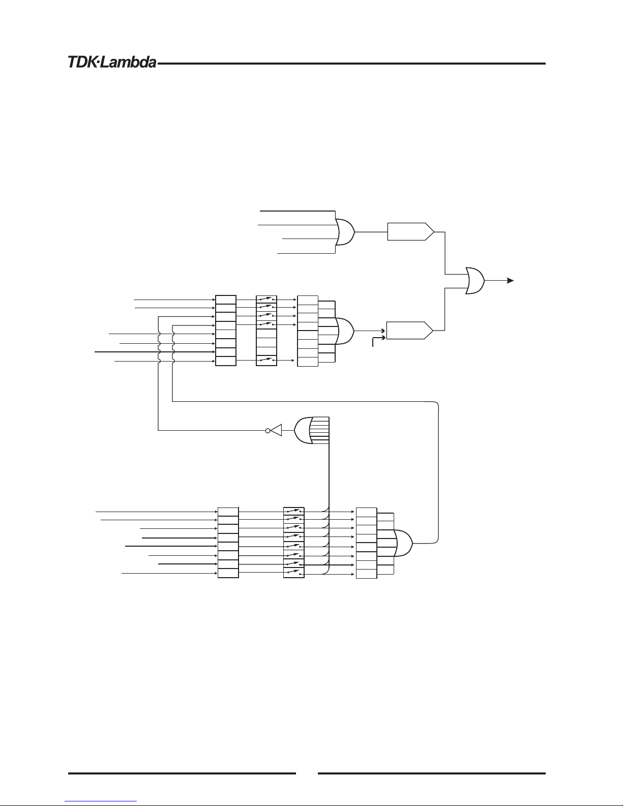
OR
OR
OR
SRQ
Messages
Address
Changed
Response
messages
Command Error (”Cnn”)
Execution Error (”Enn”)
Query Response (”message”)
Command Response (”OK”)
CV
CC
NFLT
FLT
AST
FDE
0
LCL
CV
CC
NFLT
FLT
0
0
0
LCL
0
0
0
OR
Status Registers
Condition
Enable
Event
Constant Voltage
Constant Current
No Fault
Fault
Auto Start
Fold Enabled
Spare
Local Mode
0
1
2
3
4
5
6
7
“STAT?”
“SENA xx”
“SENA?”
“SEVE?”
0
AC
OTP
FLD
OVP
SO
OFF
ENA
Fault Registers
Condition
Enable
Spare
AC Fail
Over Temperature
Foldback (tripped)
Over Volt Prot
Shut Off (rear panel)
Output Off (front panel)
Enable Open
0
1
2
3
4
5
6
7
“FLT?”
“FENA xx”
“FENA?”
0
AC
OTP
FLD
OVP
SO
OFF
ENA
OR
Event
“FEVE?”
MSB
MSB
LSB
Serial
TXD
LSB
One response for every command
or query received.
One SRQ when SEVE goes
from all zeroes to any bit set.
Setting more SEVE bits does
not cause more SRQs.
Positive Logic:
0 = No Event
1 = Event Occured
7.8 STATUS, ERROR AND SRQ REGISTERS
This section describes the various status error and SRQ registers structure. The registers can be
read or set via the RS232/485 commands. When using the IEEE option, refer to the user manual
for Genesys Power Supply IEEE Programming interface.
Refer to Fig.7-7 for the Status and Error Registers Diagram.
7.8.1 General
TM
Fig.7-7: Status and Error Registers Diagram
7.8.2 Conditional registers
The fault Condition Register and the Status Condition Register are read only registers that the user
may read to see the condition of the supply. Refer to table 7-8 for description of the Fault Condition
Register bits and Table 7-9 for the Status Condition register bits.
SRQ = “!nn”,
nn = address
58
Page 67

7.8.2 Conditional registers
7.8.3 Service Request: Enable and Event Registers
The conditional Registers are continuously monitored. When a change is detected in a
register bit which is enabled, the power supply will generate an SRQ message.
The SRQ message is: "!nn" terminated by CR, where the nn is the power supply address.
The SRQ will be generated either in Local or Remote mode.
Output is ON and the supply is not in
CV.
Output is On and the
supply in CV.
Output is ON and the supply is not in
CC.
Output is ON and the
supply in CC.
The power supply is
operating normally or
fault reporting is not
enabled.
See “OUT n”
command in Section
7.7.5.
One or more faults are active and
fault reporting is enabled (using
“FENA xx”).
1
2
Constant
Voltage
Constant
Current
No Fault
Table 7-7: Fault Condition Register
BIT
Fault name
Fault symbol
Bit Set condition
Bit Reset condition
Fixed to zero
Fixed to zeroSPARESpare bit
0 (LSB)
The AC input returns to normal.
AC fail has occurred.
OTP shutdown has
occurred.
The power supply cools down.
Foldback shutdown
has occurred.
The supply output is turned On by
front panel button or OUT 1
command.
The supply output is turned On by
front panel button or OUT 1
command.
The supply output is turned On by
front panel button or OUT 1
command.
OVP shutdown has
occurred.
Rear panel J "Shut
Off" condition has
occurred.
Rear panel J1 "Shut Off" condition
removed.
Front panel OUT
button pressed to Off.
Rear panel J1 Enable
terminals(J1-1&J1-14)
opened.
Rear panel J1 Enable terminals closed.
1
2
3
4
5
6
7(MSB)
AC Fail
Over
temperature
Foldback
Over
voltage
Shut Off
Output Off
Enable
AC
OTP
FOLD
OVP
SO
OFF
ENA
Table 7-8: Status Condition Register
BIT
Status name
Status symbol
Bit Set condition
Bit Reset condition
0 (LSB)
CV
CC
NFLT
One or more faults are
enabled and occur.
Fault Event Register cleared (FEVE?).
Supply is in AutoRestart mode (from
Front Panel or serial
command).
Supply is in Safe-Start mode (from
Front Panel or serial command).
Fold protection
enabled (from Front
Panel or serial
command).
Fold protection disabled (from Front
Panel or serial command).
Fixed to zero.
Fixed to zero.
Supply in Local mode.
Supply in Remote mode or LocalLockout mode.
3
4
5
6
7 (MSB)
Fault
active
Fold
Enabled
Spare bit
Local Mode
FLT
FDE
SPARE
LCL
AST
AutoRestart
Enabled
59
Page 68
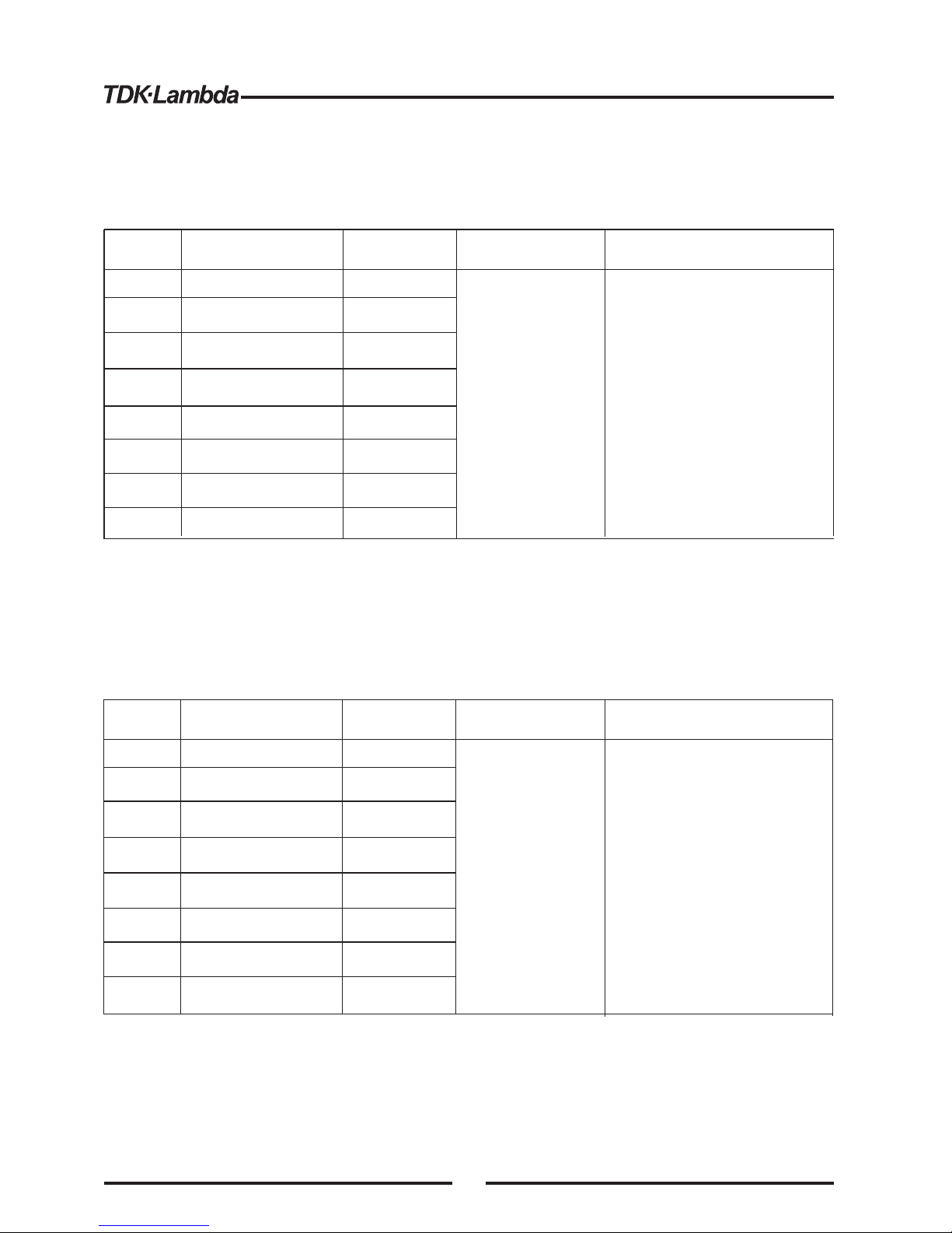
Refer to Tables 7-9 to 7-12 for details of the Enable and Event registers.
The Fault Enable Register is set to the enable faults SRQs.
1.Fault Enable Register
2.Fault Event Register
The Fault Event will set a bit if a condition occurs and it is enabled. The register is cleared when
FEVE?, CLS or RST commands are received.
Table 7-9: Fault Enable Register
BIT
Enable
bit name
Fault symbol
0 (LSB)
1
2
3
4
5
6
7(MSB)
Spare bit
AC Fail
Over Temperature
Foldback
Over Voltage
Shut Off
Output Off
Enable
SPARE
AC
OTP
FOLD
OVP
SO
OFF
ENA
Bit Set condition
Bit reset condition
User command:
"FENA nn" where
nn is hexadecimal
User command: "FENA nn"
where nn is hexadecimal (if
nn="00", no fault SRQs will
be generated).
Table 7-10: Fault Event Register
0 (LSB)
1
2
3
4
5
6
7(MSB)
Spare bit
AC Fail
Over Temperature
Foldback
Over Voltage
Shut Off
Output Off
Enable
SPARE
AC
OTP
FOLD
OVP
SO
OFF
ENA
Entire Event Register is
cleared when user sends
"FEVE?" command to read
the register.
"CLS" and power-up also
clear the Fault Event
Register. (The Fault Event
Register is not cleared by
RST)
BIT
Event
bit name
Fault symbol
Bit Set condition
Bit reset condition
Fault condition
occurs and it is
enabled.
The fault can set
a bit, but when
the fault clears
the bit remains
set.
60
Page 69
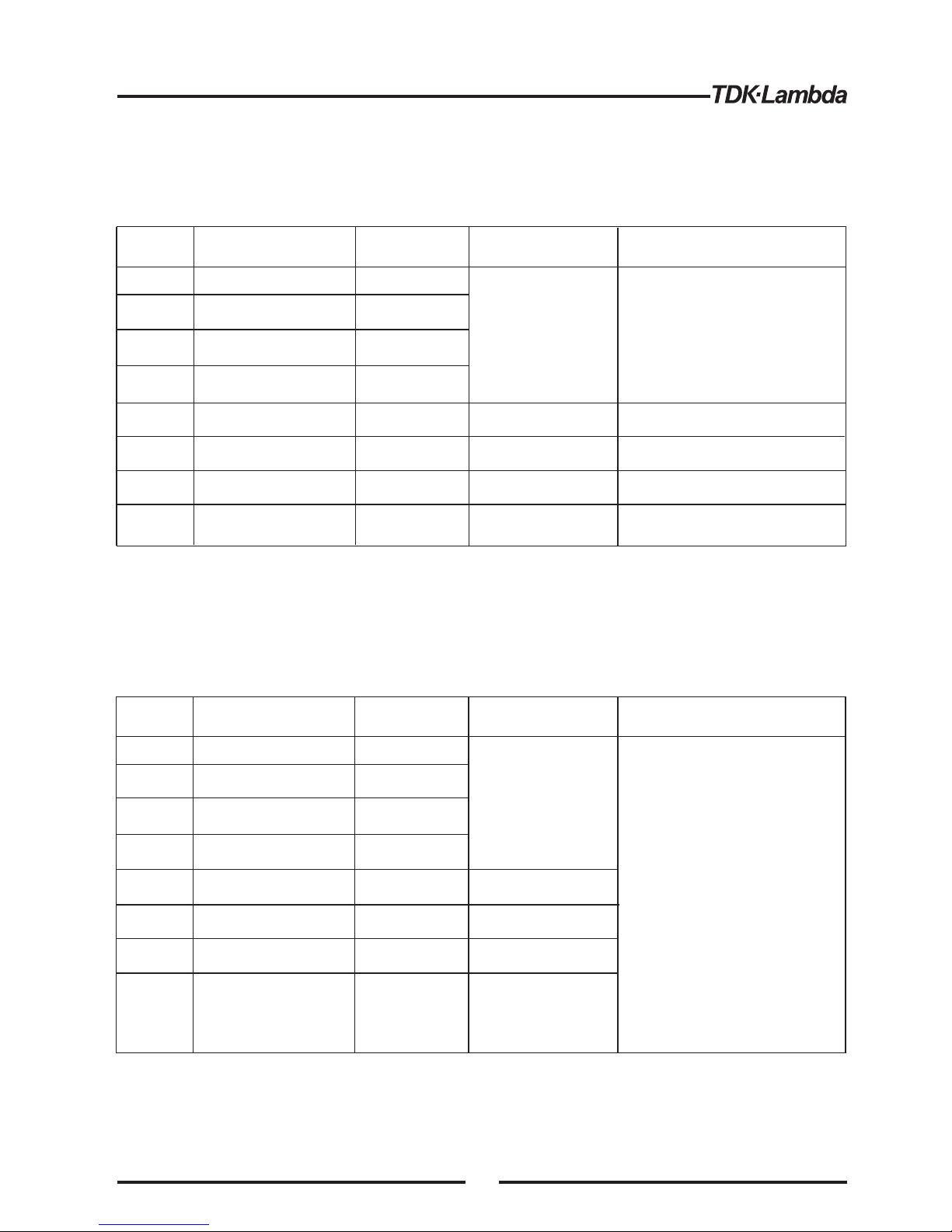
Table 7-11: Status Enable Register
BIT
Status symbol
0 (LSB)
1
2
3
4
5
6
7(MSB)
Constant Voltage
Constant Current
No Fault
Fault active
Auto-Restart enabled
Fold enabled
Spare
Local Mode
CV
CC
NFLT
FLT
AST
FDE
Spare
LCL
Bit Set condition
Bit reset condition
User command:
"SENA nn" is
received,
where nn is
hexadecimal bits.
User command: "SENA nn"
is received, where nn is
hexadecimal bits.
If "nn"=00, no SRQ is sent
when there is a change in
Status Condition Register.
Table 7-12: Status Event Register
0 (LSB)
1
2
3
4
5
6
7(MSB)
Constant Voltage
Constant Current
No Fault
Fault active
Not used
Not used
Not used
Local Mode
CV
CC
NFLT
FLT
0
0
0
LCL
Entire Event Register is
cleared when user sends
"SEVE?" command to read
the register.
"CLS" and power-up also
clear the Status Event
Register. (The Fault Event
Register is not cleared by
RST)
BIT
Status
name
Status
symbol
Bit Set condition
Bit reset condition
Changes in status
occurs and it is
enabled.
The change can
set a bit, but when
the change clears
the bit remains
set.
3.Status Enable register
The Status Enable Register is set by the user to enable SRQs from changes in power supply
status.
Status name
Always zero
Always zero
Always zero
Always zero
Always zero
Always zero
"SENA nn"
command
"SENA nn"
command
4.Status Event Register
The Status Event Register will set a bit if a change in the power supply status occurs and it is
enabled. The register is cleared when the "SEVE?" or "CLS" commands are received. A change
in this register will generate SRQ.
Always zero
Always zero
Always zero
Unit is set to Local
by pressing front
panel REM/LOC
button.
61
Page 70

7.9 SERIAL COMMUNICATION TEST SET-UP
Use the following instructions as basic set-up to test the serial communication operation.
1.Equipment:
2.PC set-up:
3.Power supply set-up:
4.Communication Test:
PC with Windows Hyper Terminal, private edition, software installed, Genesys
power supply, RS232 cable.
TM
2.1 Open Hyper Terminal.......................New Connection.
2.2 Enter a name
2.3 Connect to.......................................Direct to Com1 or Com 2
2.4 Configure port properties:
2.5 Open Properties in the program File...........................Properties
2.6 Setting: ASCII Set Up
Select Echo characters locally, select send line ends with line feed.
On some PC systems, pressing the number keypad "Enter" will
distort displayed messages. Use the alphabetic "Enter" instead.
Bits per second .......9600
Data bits ..................8
Parity .......................None
Stop bits....................1
Flow control..............None
3.1 Connect the power supply to the PC using the RS232 cable.
3.2 Set via the front panel: Baud Rate: 9600, Address: 06.
3.3 Set via the rear panel: RS232/485 to RS232 (refer to section: 4-4).
4.1 Model identification:
PC:write: ADR 06
Power supply response: "OK"
4.2 Command test:
PC write: OUT 1
Power supply response: "OK"
PC write: PV n
Power supply response: "OK"
PC write: PC n (for n values seeTables 7-3, 7-4 and 7-5)
Power supply response: "OK"
The power supply should turn on and the display will indicate the output voltage
and the actual output current.
62
Page 71
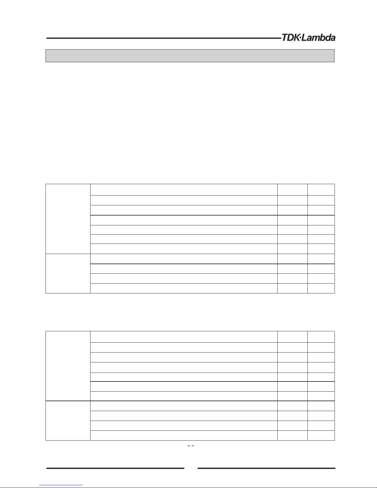
CHAPTER 8 ISOLATED ANALOG PROGRAMMING OPTION
8.1 INTRODUCTION
Isolated Analog Programming is an internal option card for analog programming of the Genesys
power supply series. The option is factory installed and cannot be obtained with GPIB (IEEE)
Interface. Output Voltage and Current Limit can be programmed and readback through optically
isolated signals which are isolated from all other ground references in the power supply.
There are two types of Isolated Analog programming cards:
1. 0-5V/0-10V option (PN: IS510): Using 0-5V or 0-10V signals for programming and readback.
2. 4-20mA option (PN: IS420): Using current signals for programming and readback.
TM
NOTE:
Use 100Kohm minimum input impedance for the monitoring circuits to minimize the readback error.
Programming
Inputs
Output voltage programming accuracy
Output current programming accuracy
Output voltage programming temperature coefficient
Output current programming temperature coefficient
Input impedance
Absolute maximum voltage
Max. voltage between program inputs and supply outputs
Output voltage monitoring accuracy
Output current monitoring accuracy
Output Impedance (see note)
Max. voltage between monitoring outputs and supply outputs
%
%
PPM/ C
PPM/ C
Ohm
Vdc
Vdc
%
%
Ohm
Vdc
o
o
+/-1
+/-1
+/-100
+/-100
1M
0-15
600
+/-1.5
+/-1.5
100
600
Programming
Inputs
Output voltage programming accuracy
Output current programming accuracy
Output voltage programming temperature coefficient
Output current programming temperature coefficient
Input impedance
Absolute maximum input current
Max. voltage between program inputs and supply outputs
Output voltage monitoring accuracy
Output current monitoring accuracy
Maximum load impedance
Max. voltage between monitoring outputs and supply outputs
%
%
PPM/ C
PPM/ C
Ohm
mA
Vdc
%
%
Ohm
Vdc
o
o
+/-1
+/-1
+/-200
+/-200
50
0-30
600
+/-1.5
+/-1.5
500
600
8.2.2 4-20mA option (PN: IS420)
8.2.1 0-5V/0-10V option (PN: IS510)
8.2 SPECIFICATIONS
Monitoring
Outputs
Monitoring
Outputs
63
Page 72
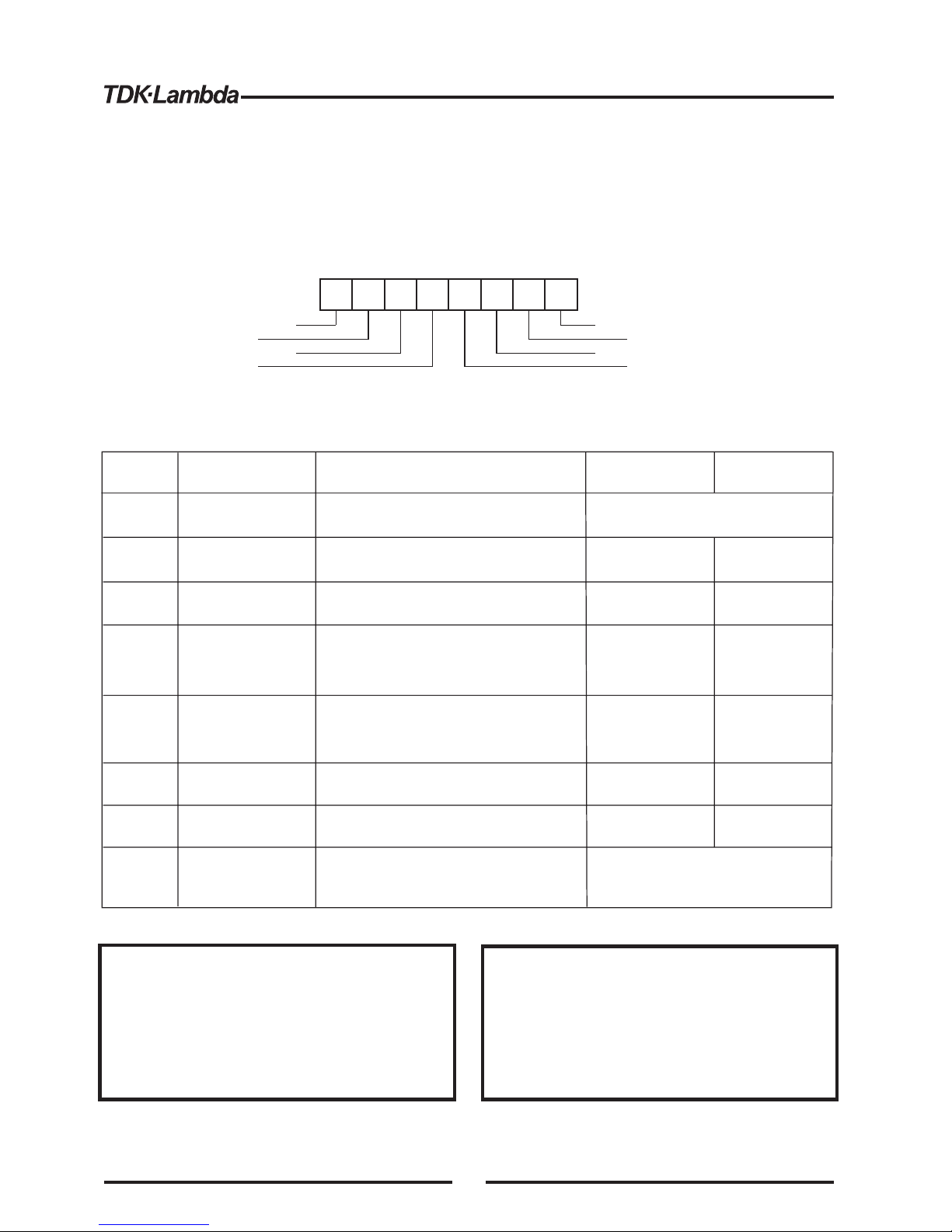
8.3 ISOLATED PROGRAMMING & MONITORING CONNECTOR
Refer to Table 8-1 for detailed description of the rear panel Isolated Programming & Monitoring
connector. To provide the lowest noise performance, it is recommended to use shielded-twisted
pair wiring.
Refer to Fig.8-1 for description of the connector.
1
2
3
4
5
6
7
8
Shield
+VPROG_ISO
+IPROG_ISO
GND
Shield
+IMON_ISO
+VMON_ISO
GND
+VPROG_ISO
Terminal
Signal name
Function
Shield, connected internally to
chassis of the supply.
0-5/0-10V
0-5/0-10V
0-5/0-10V
0-5/0-10V
4-20mA
4-20mA
4-20mA
4-20mA
Range 0-5/0-10V
IS510 option
Range 4-20mA
IS420 option
Chassis ground
Chassis ground
SHLD
1
Output voltage programming input
Output current programming input
2
+IPROG_ISO
3
Ground for programming
signals.
Ground for programming
signals.
Output voltage monitoring output
Output current monitoring output
Shield, connected internally to
chassis of the supply.
GND
GND
+VMON_ISO
+IMON_ISO
SHLD
4
5
6
7
8
Ground
Ground
Ground
Ground
Table 8-1: Detailed description of Isolated programming & Monitoring connector
Fig.8-1: Isolated Programming & Monitoring connector
Isolated programming plug P/N: MC1.5/8-ST-3.81, Phoenix.
When the Isolated Analog Option is installed, do not
apply any signals to the non-isolated VPGM and IPGM
(J1-9 and J1-10) pins. All other J1 features may be used
normally. Refer to Section 4.5 for a description of J1
features.
CAUTION
VORSICHT
Wenn die optionale Ansteuerung mit isolie rten
Analogsignalen verwendet wird, legen Sie keinerlei
Signale an die nicht isolierten Pins VPGM oder lPGM
(J1-9 und J1-10) der Standardschnittstelle J1. Alle
übrigen J1-Funktionen können normal verwendet
werden.
Siehe Abschnitt 4.5 für eine Beschreibung der J1Funktionen.
64
Page 73

SW1 position 3 and 4 must be in their Up position for
operation with 4-20mA Isolated Programming and
Monitoring.
To prevent damage to the unit, do not program
the output voltage and current to higher then the
power supply rating.
Perform the following procedure to configure the power supply:
1. Turn the power supply AC power switch to Off.
2. Connect a short between J1-8 and J1-12 (refer to Table 4-4).
3. Set Setup switch SW1-1 to its UP position for Output Voltage external programming
and SW1-2 to its UP position for Output Current limit external programming.
4. Set SW1 position 3 to select the programming voltage range: Down=0-5V,Up=0-10V.
5. Set SW1 position 4 to select the monitoring range: Down=0-5V,Up=0-10V.
6. Ensure that SW1 positions 7 and 8 are in the their down position.
7. Connect the programming sources to the mating plug of the Isolated Programming
connector.Observe for correct polarity of the voltage source.
8. Set the programming sources to the desired levels and turn the power supply ON.
Perform the following procedure to configure the power supply:
1. Turnthe power supplyAC power switch to Off.
2. Connect a short between J1-8 and J1-12 (refer to Table 4-4).
3.Set setup switch SW1-1 to itsUP position for Output Voltage external programming and
SW1-2 to its UP position for Output Current limit external programming.
4. Set SW1 position 3 to it's Up position.
5. Set SW1 position 4 to it's Up position.
6. Ensure that SW1 positions 7 and 8 are in their Down position.
7. Connect the programming source to the mating plug of the Isolated Programming
connector.Observe for correct polarity of the voltage source.
8. Set the programming sources to the desired levels and turn the power supply ON.
8.4.2 Setting up the power supply for 4-20mA Isolated Programming and Monitoring
8.4.1 Setting up the power supply for 0-5/0-10V Isolated Programming and Monitoring
8.4 SETUP AND OPERATING INSTRUCTIONS
J1-8 and J1-12 must be shorted together with a jumper.
J1-8 and J1-12 must be shorted together with a jumper.
CAUTION
VORSICHT
HINWEIS
HINWEIS
HINWEIS
NOTE
NOTE
NOTE
Um das Gerät vor Schäden zu schützen,
programmieren Sie keine Spannungs- oder
Stromwerte, die über den maximalen
Nennwerten liegen.
Für die isolierte Programmierung und Überwachung
mittels 4-20mA-Signalen müssen die Schalter 3 und 4
von SW1 in der oberen Position stehen.
J -8 und J - 2 müssen über einen Jumper miteinander
verbunden werden.
1 1 1
J -8 und J - 2 müssen über einen Jumper miteinander
verbunden werden.
1 1 1
65
Page 74

9.1 INTRODUCTION
9.2 UNITS UNDER WARRANTY
9.3 PERIODIC MAINTENANCE
9.4 ADJUSTMENTS AND CALIBRATION
9.5 PARTS REPLACEMENT AND REPAIRS
This chapter provides information about maintenance, calibration and troubleshooting.
Units requiring repair during the warranty period should be returned to a Lambda authorized service
facility. Refer to the addresses listing on the back cover of this manual. Unauthorized repairs
performed by other than the authorized service facilities may void the warranty.
No routine maintenance of the power supply is required except for periodic cleaning. To clean,
disconnect the unit from the AC supply and allow 30sec. for discharging internal voltage. The front
panel and the metal surfaces should be cleaned using mild solution of detergent and water. The
solution should be applied onto a soft cloth, and not directly to the surface of the unit. Do not use
aromatic hydrocarbons or chlorinated solvents for cleaning. Use low pressure compressed air to
blow dust from the unit.
No internal adjustment or calibration is required. There is NO REASON to open the power supply
cover.
As repairs are made only by the manufacturer or by authorized service facilities, no parts
replacement information is provided in the manual. In case of failure, unusual or erratic operation of
the unit, contact a Lambda sales or service facility nearest you. Please refer to the Lambda sales
offices addresses listing on the back cover of this user manual.
If the power supply appears to operating improperly, use the troubleshooting guide to determine
whether the power supply, load or external control circuit are the cause.
Configure the power supply for basic front panel operation and perform the tests of section 3.8 to
determine if the problem is with the supply.
Table 9-1 provides the basic checks that can be performed to diagnose problems, and references to
sections of this manual for further information.
9.6 TROUBLESHOOTING
Table 9-1: Troubleshooting guide
Check continuity, replace
if necessary.
Does the AC source voltage
sag when load is applied?
No output. All displays and
indicators are blank.
Is the AC power cord
defective?
SYMPTOM
CHECK
ACTION
REF.
Is the AC input voltage
within range?
Check input AC voltage.
Connect to
appropriate
voltage source.
Check input AC voltage.
Connect to appropriate
voltage source.
Output is present momentarily
but shuts off quickly. The display
indicates "AC".
3.7
3.6
3.7
3.6
CHAPTER 9 MAINTENANCE
66
Page 75

Check if the positive or
negative load wire is loose.
Output is present momentarily
but shuts off quickly. the display
indicates "OUP".
SYMPTOM
CHECK
ACTION
REF.
3.9.6
3.9.8
Is the power supply
configured to Remote
sense?
Output voltage will not adjust.
Front panel CC LED is on.
Is the unit in constant current
mode?
Check current limit setting
and load current.
5.2.1
5.2.2
Output voltage will not adjust.
Front panel CV LED is on.
Check if output voltage is
adjusted above OVP setting
or below UVL setting.
Set OVP or UVL so they
will not limit the output.
Output current will not adjust.
Front panel CV LED is on.
Is the unit in constant voltage
mode?
Check current limit and
voltage setting.
5.3
5.4
5.2
Check load and sense
wires connection for noise
and impedance effects.
Minimize the drop on the
load wires.
Turn off the AC power
switch. Check load
connections. If analog
programming is used,
check if the OVP is set
lower than the output.
Check rear panel J1
ENABLE connection.
Setup switch SW1 setting.
Check rear panel J1
Output Shut-Off connection.
Check if air intake or
exhaust are blocked.
Check if the unit is
installed adjacent to heat
generating equipment.
Check Foldback setting
and load current.
Connect the sense wires
according to User's
manual instructions.
Turn Off the AC power
and wait until the display
turns off. Turn on the AC
power and press front
panel REM/LOC button.
9.7 FUSE RATING
There are no user replaceable fuses in the power supply. Internal fuses are sized for fault
protection and if a fuse was opened it would indicate that service is required. Fuse replacement
should be made by qualified technical personnel. Refer to Table 9-2 for a listing of the fuses.
Table 9-2: Internal fuses
Is the power supply in remote
sense?
Is the voltage drop on the
load wire high?
Display indicates "ENA"
Display indicates "SO"
Over Voltage Protection
circuit is tripped.
Display indicates "O7P"
Display indicates "Fb"
Are sensing wires
connected properly?
Is the power supply in
Local-Lockout mode?
3.9.4
3.9.8
5.3
5.8
4.4
5.7
5.5
5.12
3.9.8
7.2.5
The front panel controls are
nonfunctional.
Poor Load regulation
Front panel CV LED is on.
No output. Front panel ALARM
LED is blinking.
No output. Display indicates
"OUP"
Large ripple present in output.
Fuse designation
1-Phase, 190-240Vac
3-Phase, 190-240Vac
INPUT FUSE
F301, F302 :
30A, 250VAC, Fast-Acting
F321,F322, F323:
15A, 250VAC, Fast-Acting
67
Page 76

Kapitel 9 Wartung & Service
9.1 Einleitung
Dieses Kapitel liefert Informationen über Wartung und Fehlersuche.
9.2 Reparaturen während der Garantie
Sollte ein Gerät innerhalb der Garantiezeit ausfallen, so dürfen Reparaturen nur durch Lambda oder
autorisierte Servicestellen durchgeführt werden. Die Adressen finden Sie am Ende dieses
Handbuches. Eingriffe in die Geräte durch nicht autorisierte Stellen führen zum Verlust des
Garantieanspruches.
9.3 Periodische Wartung
Die Geräte sind wartungsfrei. Wir empfehlen jedoch die regelmäßige Reinigung. Trennen Sie die
Einheit vom Versorgungsnetz und warten Sie 30 Sekunden um sicherzugehen, dass sich interne
Spannungen abgebaut haben. Die Frontabdeckung und die Metalloberflächen sollten mit einer milder
Lösung von Reinigungsmittel und Wasser gesäubert werden. Die Lösung sollte auf ein weiches Tuch
aufgetragen werden, und nicht direkt auf Oberfläche der Geräte. Benutzen Sie keine Reinigungsmittel
die aromatische Kohlenwasserstoffe, Chlor Lösungsmittel enthalten. Benutzen Sie schwach
komprimierte Pressluft, um das Gerät von Staub zu befreien.
9.4 Justagen und Kalibrierung
Interne Justage oder Kalibrierung ist nicht nötig. Es gibt keinen Grund, die Stromversorgung zu öffnen.
9.5 Bauteilewechsel und Reparaturen
Da Reparaturen nur durch den Hersteller oder autorisierte Servicestellen durchgeführt werden dürfen,
enthält das Handbuch keine Schaltpläne. Im Falle eines defektes oder ungewöhnlichem Verhalten
des Gerätes, setzen Sie sich bitte mit der nächstgelegenen Lambda Niederlassung in Verbindung. Die
Adressen finden Sie am Ende dieses Handbuches.
9.6 Fehlersuche
Sollte die Stromversorgung nicht wie erwartet funktionieren, kann ihnen die nachfolgende Tabelle
helfen, herauszufinden ob die Stromversorgung, die Last oder eine externe Steuerung die Ursache
dafür ist.
Stellen Sie das Netzgerät so ein, dass es mit den Reglern und Tasten am Frontpanel bedient werden
kann. Führen Sie dann die Tests aus Abschnitt 3.8 durch um festzustellen, ob das Problem durch das
Netzgerät verursacht wird.
Tabelle 9-1 führt Sie Schritt für Schritt durch die Prüfungen, die durchgeführt werden sollten, um die
Fehlerursache zu ermitteln und gibt ihnen Hinweise auf Abschnitte dieses Handbuches in denen Sie
weiterführende Informationen finden können.
68
Page 77

Tabelle 9-1: Fehlersuche
Symptom Prüfung Tätigkeit Ref.
Keine Ausgangsspannung.
Displays und Anzeigen sind
dunkel.
Ist das Netzkabel defekt?
Ist die Netzspannung
innerhalb des
Eingangsbereiches?
Falls erforderlich, Netzkabel
ersetzen.
Netzspannung prüfen, Gerät an
passende Versorgungsspannung
anschließen.
3.7
3.6
Ausgangsspannung liegt
kurzfristig an, schaltet aber
sofort wieder ab. Das Display
zeigt „AC“ an.
Bricht die Netzspannung
zusammen wenn am Ausgang
die Last angeschlossen wird?
Netzspannung prüfen, Gerät an
passende Versorgungsspannung
anschließen.
3.6
Ausgangsspannung liegt
kurzfristig an, schaltet aber
sofort wieder ab. Das Display
zeigt „OUP“ an.
Werden die Sense
Anschlüsse benutzt?
Prüfen, ob die Lastleitungen
ordnungsgemäß angeschlossen
sind.
3.9.6
3.9.8
Ausgangsspannung kann
nicht eingestellt werden. CCLED am Frontpanel leuchtet.
Arbeitet das Gerät im
Konstantstrom-Modus?
Strombegrenzungseinstellungen
und Laststrom prüfen.
5.2.1
5.2.2
Ausgangsspannung kann
nicht eingestellt werden. CVLED am Frontpanel leuchtet.
Prüfen, ob die Einstellung für
die Ausgangsspannung über
der OVP oder unter der UVL
Einstellung liegt.
OVP oder UVL so einstellen,
dass keine Einschränkung im
gewünschten Bereich erfolgt.
5.3
5.4
Ausgangsstrom kann nicht
eingestellt werden.
CV-LED am Frontpanel
leuchtet.
Arbeitet das Gerät im
Konstantspannungs-Modus?
Strombegrenzung und
Spannungseinstellungen prüfen.
5.2
Die Ausgangsspannung hat
eine hohe Restwelligkeit.
Werden die Sense
Anschlüsse benutzt?
Ist der Spannungsfall über die
Lastleitungen sehr hoch?
Last- und Senseleitungen auf
gute Verbindung prüfen.
Spannungsfall an den
Lastleitungen verringern.
3.9.4
3.9.8
Keine Ausgangsspannung.
Am Display wird „OUP“
angezeigt.
Der Überspannungsschutz ist
aktiv.
Gerät mit dem Netzschalter
abschalten. Lastverbindungen
prüfen. Falls analoge
Programmierung verwendet wird
prüfen, ob die Einstellungen für
den OVP niedriger als die
Ausgangsspannung eingestellt
ist.
5.3
Keine Ausgangsspannung.
Alarm LED am Frontpanel
blinkt.
Das Display zeigt „ENA“ an.
Das Display zeigt „SO“ an.
Das Display zeigt „OTP“ an.
Das Display zeigt „Fb“ an.
An der Rückseite den ENABLE
Anschluss an J1 prüfen.
SW1 ordnungsgemäß einstellen.
An der Rückseite den SHUT-OFF
Anschluss an J1 prüfen.
Prüfen, ob die Lüftungsöffnungen verschlossen sind oder
ob sich Heizquellen in der Nähe
befinden.
Foldback Einstellung und
Laststrom prüfen.
5.8
4.4
5.7
5.12
5.5
Schlechte Lastregelung.
CV-LED am Frontpanel
leuchtet.
Sind die Sense-Leitungen
ordnugsgemäß
angeschlossen?
Sense-Leitungen laut
Anweisungen im Handbuch
anschließen.
3.9.8
Bedienelemente am
Frontpanel sind ausser
Funktion.
Wird das Gerät im LocalLockout Modus betrieben?
Gerät ausschalten und warten bis
die Anzeigen erloschen sind.
Gerät wieder einschalten und
REM/LOC Taste am Frontpanel
betätigen.
7.2.5
69
Page 78
9.7 Sicherungswerte
Im Gerät befinden sich keine Sicherungen die durch den Anwender ersetzt werden können.
Sicherungen sind als Schutz eingebaut, falls im Gerät Fehler auftreten sollten. Sollte eine Sicherung
auslösen, so muss das Gerät zur Reparatur gegeben werden. Sicherungen dürfen ausschließlich von
dafür geschultem, technischen Personal ausgewechselt werden. In Tabelle 9-2 sind die
Sicherungswerte aufgelistet.
Tabelle 9-2: Interne Sicherungen
Sicherungs-Bezeichnung 1-phasig, 190-240Vac 3-phasig, 190-240Vac
Eingangssicherung F301, F302:
30A, 250Vac, Fast-Acting
F321, F322, F323:
15A, 250Vac, Fast-Acting
70
Page 79

USER MANUAL INDEX
A
B
C
D
E
F
G
H
ac cables
ac fail
accessories
acknowledge
address
adjustment
auto-restart
back space
baud rate
bipolar voltage
calibration
configuration
checksum
communication
constant current
constant voltage
cooling
cv indicator
cc indicator
daisy-chain
display
enable
error message
external resistor
external voltage
fine
foldback
fuse
front panel control
front panel locking
grounding
global output command 56
humidity
hyper terminal
I
J
L
M
O
P
R
S
ID control
initialization
installation
isolated
J1
J2
J3
last setting memory
linking power supplies
line feed
local operation
local sensing
lock front panel
maintenance
otp
outline
over voltage
parallel operation
parity
ps_ok
preview
rack mounting
rear panel
remote sensing
remote/local
registers structure
RS232
RS485
RXD
RX(RS232)
safe start
safety
series operation
shield
specifications
status control
SRQ
shut-off
SW1
T
U
V
W
TXD
TX(RS232)
under voltage limit
volts display
warranty
wire size
9, 16
30
9
52
19, 49
66
39
53
19, 49
41
66
49
52
52, 62
18, 35
18, 35
9, 11
28, 38
28, 38
44, 52
28
34
53
47
46
30
19, 37
67
28
44
25
11
62
53
54
14
63
33, 46, 47
17, 26
50
29, 39
52
52
35
26
44
66
42
52
39
13
28,36
42
62
38, 44
29
14
30
27
29
58
49, 50, 51
49, 50, 51
50, 51
50, 51
39
4
39
50
10, 63
57, 58
58
37
31, 32
50, 51
50, 51
18, 37
28
1, 66
20
Master/Slave
MD
71
Page 80

NOTES
 Loading...