

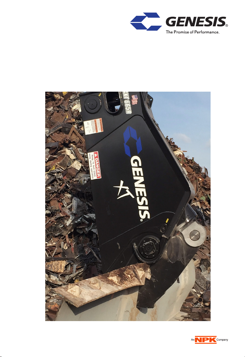
XT Mobile Shear
Reference Guide

2 1
7
15 16 17 18
19
3 4 5 6
8 9
14
13
12
11
10
This document is a quick reference only. It does not replace the GXT Safety and Operator’s Manual, which must be followed by all operators and maintenance personnel.
2
1 Slewing ring – connects the shear head to the shear stick or body;
not used on straight shears
2 Sub-head – houses and protects the hydraulic components used for 360º rotation
3 Stick-pin connection location or linkage connection on 3rd member applications
4 Boom pivot connection location or stick-pin connection on 3rd member applications
5 Rear cylinder pin for the main cylinder
6 Stick or body – houses and protects the main hydraulic cylinder
7 AutoGuide or puck bolts – the dry torque value for these bolts on all GXT shears
is 900 ft-lb
8 Pivot group – includes the end cap, tie rod and tie rod nut
9 Lower shear jaw
10 Chin – keep top edge built up, maintain radiuses in razor blade pocket
after build-up and hard-surfacing
11 Razor blade – NEVER insert shims behind
12 Dual guide blades – insert shims between the adjustment plate and blade when
setting/adjusting blade gap
Note: from the operator’s view, the left guide blade may or may not have an adjustment
plate. If not, insert shim(s) directly against the back of the guide blade.
13 Upper and lower secondary cutting blades. Only insert shims behind the lower,
placing between the adjustment plate and blade when setting/adjusting blade gap.
14 Upper and lower primary cutting blades. Only insert shims behind the lower,
placing between the adjustment plate and blade when setting/adjusting blade gap.
15 Upper shear jaw – never shim blades in upper jaw
16 Protection strips – raised areas of parent material along the blade pockets on
upper and lower jaws, should be flush to 0.010" below the blade faces
17 Rhino horn
18 Tang – parent material under and between the piercing tip blades
19 Piercing tip blades – NEVER insert shims behind
3

4-HOUR CHECKLIST
Every four hours, perform a brief visual check for hydraulic leaks, blade damage, loose
or missing bolts, and cylinder pin keepers. A more thorough inspection, to be performed
at the end of each shift, is described below on the eight-hour checklist.
Grease: • Shear cylinder - end of pin
• Shear cylinder rod
• AutoGuide at fitting and smear grease on contact surface of upper jaw
• Main shaft/pivot, both sides
Grease all locations until grease extrusion is visible with jaw open and closed.
8-HOUR CHECKLIST
Inspect: • Bolts - check for loose bolts, replace if damaged
• Fittings and hoses for damage or leaks
• Bracket pivot for wear and pin retainers
• Cylinder pivot for wear and pin retainers
• Entire shear for cracks (visual check)
Grease: • Bracket pivot
• Bracket cylinder
• Bearing slewing - four locations
• All points listed in 4-hour checklist
Grease all locations until grease extrusion is visible.
Jaws and
• Check blade gaps, see page 7 for minimum and maximum
blades:
• Check blade edge radiuses
• Check for loose or damaged bolts, retorquing loose bolts when cool
• Check AutoGuide, shim to tolerance and replace when shims exceed
0.100"
• Build-up and hard-surface as required
• Grind off any rolled-over or mushroomed blade edges
• Shear Jaw Armor™ - build-up and hard-surface as needed
Piercing Tip
Wet Bolt Torque
Model Ft-lb
115 & 225 282
335 - 555 682
665 - 2555 1363
Grease under bolt head and in tip
threaded holes
This document is a quick reference only. It does not replace the GXT Safety and Operator’s Manual, which must be followed by all operators and maintenance personnel.
4
Cutting and Guide Blade
Dry Bolt Torque
Model Ft-lb
115 & 225 376
335 - 555 606
665 - 2055 900
2555 1817
Razor Blade
Dry Bolt Torque
Model Ft-lb
115 & 225 376
335 - 555 606
665 - 2555 900
 Loading...