

Page 1

Luminite Genesis product range
Wireless PIR detectors
G1 Wireless PIR’s 30m x 20m LGWP3020
G1 Wireless PIR’s 15m x 20m LGWP1520
G1 Wireless PIR’s 40m x 4.5m LGWP4004
G1 Wireless PIR’s 12m Horizontal curtain LGWP12HC
G1 Wireless PIR’s 12m Vertical curtain LGWP12VC
G2 Wireless PIR’s 30m x 20m LG2WP3020
G2 Wireless PIR’s 60m x 4m LG2WP6004
Wireless Accessories
IP Masthead/Repeater LGIP MT434
Masthead/Repeater LGMT434
Masthead Relay Unit LGMRU4x4
Relay Expansion Module LGREM4x4
Walk Test Instrument LGWT434
16 way relay unit LGRU16
Relay module LGRM8
16 way DM interface unit LGDM16
16 way relay unit with end of line resistor LGRU16ELR 3 versions
Relay module with end of line resistor LGRM8ELR 3 versions
Optional antenna AE434
Transmitter module LGTX434
Hard wired PIR detectors
G1 Wired PIR’s 30m x 20m LGHW3020
G1 Wired PIR 15m x 20m LGHW1520
G1 Wired PIR 40m x 4.5m LGHW4004
G1 Wired PIR 12m horizontal curtain LGHW12HC
G1 Wired PIR 12m vertical curtain LGHW12VC
G2 Wired PIR’s 30m x 20m LG2HW3020
G2 Wired PIR’s 60m x 4m LG2HW6004
LUMINITE ELECTRONICS LTD, 2a BELLEVUE ROAD, FRIERN BARNET, LONDON, N11 3ER
Tel: 0044 (0) 208 368 7887 Fax: 0044 (0) 208 368 3952
Web: www.luminite.co.uk email: sales@luminite.co.uk
Wireless
Wireless
PIR Detector
PIR Detector
Installation
Installation
Handbook
Handbook
2a BELLEVUE ROAD, FRIERN BARNET, LONDON, N11 3ER
Tel: 0044 (0) 208 368 7887 Fax: 0044 (0) 208 368 3952
Type: LG2 WP-3020 & WP-6004
V2 Issue 1
Page 2

PRE-INSTALLATION NOTES
Unpacking.
On receipt, inspect the package and contents for signs of damage. If damage
has occurred, advise the carrier and/or suppliers immediately. Inspect the contents to confirm that all items are present and undamaged. If any items are
missing or damaged, contact the supplier immediately. It is advisable that the
original carton is retained as this forms the safest transport container in the
event that a unit has to be returned for any reason.
Servicing.
This unit should not require general servicing. Any repair work should only be
undertaken by qualified service personnel.
Moisture.
Do not expose the internal electronics of this unit to moisture i.e. take care during installation or when changing batteries not to allow rain or damp into the
product. When the product is sealed it is water resistant to IP66.
Take great care of the mirror surface. Do not scratch it or allow dust or dirt to
settle on it.
Box Contents.
1 x GENESIS wireless G2 series PIR detector
1 x Rear tamper ring magnet
3 x no 8 wall plugs
3 x no 8 2” screws
1 x no 6 1/2” screw
1 x no 6 wall plug
1 x spare battery selector jumper
LG2WP-3020 & 6004 Wireless PIR Detector Specification.
Mirror type 30 metre x 20 metre or 60 metre x 4 metre.
Detection / Anti Tamper / Anti Cloaking / Shock.
Temp comp Temperature sensor compensates for extreme conditions
Batteries 2 x 1.5 volt C cells (supplied)
or 1 x 3.6 volt lithium. (not supplied)
Power supply 12 volts DC (optional instead of batteries)
IP rating 66
Enclosure High impact ABS with EPDM 1mm thick window
Colour Silver
Temperature -10 +70
LG2 WP-3020 & WP-6004 Wireless PIR Detector Installation Handbook Page 2.
LG2 WP-3020 & WP-6004 Wireless PIR Detector Installation Handbook Page 15.
Detection Patterns.
There are two
mirror versions to
choose from but the
mirrors are not interchangeable.
Model LGWP3020
Model LGWP6004
Detection range will vary according to the air temperature and surrounding environment.
For example: large areas of white concrete in very hot weather will reduce the
sensitivity as will air temperatures of 37 degrees. If these situations occur and
are present every day then it may be necessary to increase the sensitivity of the
detector by following the instructions on page 11.
Page 3

LG2 WP-3020 & WP-6004 Wireless PIR Detector Installation Handbook Page 14.
Testing & Commissioning.
Adjust the mirror to the desired direction of detection .
Plug on the battery jumper and observe the momentary HI message on the
display.
Program the setting as required. Pages 10 & 11.
It is recommended to set AND/OR to 1 and Pulse Count to at least 2.
Fit the front cover to prevent air flow around the sensor which will cause an
alarm. DO NOT PUSH THE WHITE WINDOW.
It is not necessary to secure the screw but be aware that the tamper will remain
during testing until the screw is fitted.
Using the LGWT434 Walk Test Instrument walk within the detection area,
stopping and waiting for about five seconds each time detection occurs.
The instrument will display D each time detection occurs.
Lens type will display as Type 6 for the 6004 or Type 7 for the 3020.
See the operating instructions for the walk tester for more information.
Adjust the mirror as described on page 9 and re-test until optimum coverage is
achieved.
Once you are happy that the detector is operating to your requirements, screw
the cover screw up from the bottom being careful not to cross thread it.
NB: Because the cover has a liquid tight gasket seal there will be an air
pressure build up inside the product which will gradually normalise. The side
effect of this will be to cause the sides around the gasket to lift slightly. Using
the palms of your hands, gently push the sides in and towards the wall which will
close up the gap. Be careful not to push the white window as damage will
occur.
INDEX
page
Copyright 2015 Luminite Electronics Ltd
All rights reserved. Unauthorised duplication of this handbook by any means
mechanical or electrical, is strictly prohibited without the express written permission of
Luminite Electronics Ltd.
Luminite Electronics Ltd acknowledge all registered trademarks.
Luminite Electronics Ltd reserve the right to make changes to this handbook and to its
LG2 WP-3020 & WP-6004 Wireless PIR Detector Installation Handbook Page 3.
Introduction. 4 & 5
Installation. 6
Mounting height and positioning.
Minimising false alarms.
7
Batteries 8
Mirror adjustments. 9
Programming. 10, 11
Wireless transmission code settings 11
PIR functions. 12
Testing and commissioning. 14
Detection patterns. 15
Types of tamper. 13
Page 4

Introduction
The LG2WP3020 & LG2WP6004 wireless Passive Infra Red Detectors (PIR)
have been designed to meet the newest and most demanding requirements of
the CCTV market. These new, stylish detectors are available in two different
detection patterns and use superior Black Mirror Technology to provide excellent
detection with minimal false alarms.
The two ranges are:
30 metres out x 20 metres across or
60 metres out x 4 metres across.
ENCLOSURE.
LG2 detectors have a modern styling which disguises the product’s true function
and helps them to blend in with modern architecturally designed buildings. The
front window is made of pigmented HDPE which hides the mirror and the main
body of the enclosure is ABS with a high quality paint finish. Both parts are UV
stabilized and the weather proof rating is IP65.
BLACK MIRROR TECHNOLOGY.
These new PIR’s use mirror technology instead of Fresnel lenses. The large
mirror provides significantly more optical gain which allows a thick EPDM front
filtered window to be used without the need to increase sensitivity.
White light from car headlights can cause false alarms, so it is important to filter
out this interference. Most PIR detectors use pigmented windows or Fresnel
lenses and sometimes an extra silicon filter to reduce white light, but this has the
effect of also reducing the infrared energy and consequently detection range.
The Black Mirror acts as a selective optical filter for body heat infrared with minimal loss while filtering out unwanted white light by as much as 14000 LUX.
The combination of high optical gain and white light filtering means that the electronic sensitivity is much lower and therefore the risk of false alarms from electrical interference and component noise is greatly reduced.
The other problem of running amplifiers at extremely high gain is that they reach
saturation which obscures any signature that the micro controller would use to
accurately determine the validity of a detection.
The Luminite LG2 amplifier runs at a relatively low level and with the combination of the adaptive focal length optically sharp edges of each mirror segment
together with the sophisticated detection algorithm has the result is accurate detection at various speeds and distances.
LG2 WP-3020 & WP-6004 Wireless PIR Detector Installation Handbook Page 4.
LG2 WP-3020 & WP-6004 Wireless PIR Detector Installation Handbook Page 13.
Types of tamper:
Front cover micro switch.
Activated when the cover screw is removed.
Rear tamper Hall effect and magnet.
The magnet is fixed to the wall and when the product is removed the magnet is
left behind.
Shock sensor.
Piezo sensor on mother board detects physical attack of the product.
Anti masking.
Active IR and LDR sense when the front window is obscured. These sensors
always face the same direction as the mirror.
Page 5

LG2 WP-3020 & WP-6004 Wireless PIR Detector Installation Handbook Page 12.
PIR FUNCTIONS.
Pulse count.
Counts the number of pulses caused when a person walks across the detector’s
field of view. The greater the number, the more the person has to move to
cause an alarm. Pulse count 1 is very sensitive while pulse count 4 is quite
insensitive. Experiment with the setting to optimise the results so that
persons are detected in good time but not so sensitive that the detector may be
prone to false alarm from incidental movement from trees, shrubs, loose
materials etc.
Sensitivity.
The normal setting is 0. Low sensitivity is sometimes needed to reduce the
detection distance.
Higher sensitivity increases distance but also increases the risk of false
activation from environmental conditions.
AND / OR.
The Genesis 2 PIR detector uses a Quad in line pyro sensor which
acts like two separate sensors side by side.
The AND / OR mode can select whether both sensors must detect movement
together or whether only one or the other is required.
AND gating is the best form of filtering out nuisance alarms from loose
materials, foliage and reflections.
OR gating is more sensitive and may be selected when fast moving objects are
to be detected.
Power saving.
Busy sites such as school playgrounds, car park entrances etc can cause an
unnecessarily large number of alarm transmissions.
Although these alarms may be ignored during the day time it is still wasteful of
battery power and therefore in these circumstances it is recommended that the
Power saving mode be selected.
There are four types of power saving which may be selected to suit.
1. An alarm can only be sent after 3 minutes of inactivity
2. An alarm can only be sent after 10 minutes of inactivity
3. An alarm can only be sent after 30 minutes of inactivity
4. The same as 3 but with an accumulative timer which can extend the 30
minutes if the site remains very busy.
In addition the sleep timer does not initiate after the first alarm but instead
after a build up of activity.
LG2 WP-3020 & WP-6004 Wireless PIR Detector Installation Handbook Page 5.
ADAPTIVE FOCAL LENGTH.
The mirrors have adaptive focal length which regulates the image size no matter where it is in the field of view. This enables accurate detection of a target at
various speeds and distances and also makes it easier to filter out small animal
movements.
AND OR.
The Quad in line pyro sensor splits each detection zone into two which are then
labelled A and B. The G2 detector can be configured to go into alarm with either
(A AND B) or (A OR B). AND detection is the best way to minimise false alarms
as it filters out spurious movements from loose materials and foliage.
SHOCK and CLOAK.
The G2 PIR also contains a shock sensor to detect physical attack and IR transmission anti-masking. On the hard wired version, these alerts activate the anti
masking relay but only momentarily.
BATTERIES.
Two 1.5 volt alkaline C cell batteries MN1400 LR14 are provided but the product
can also be powered from one 3.6 volt Lithium C cell battery instead.
Recommended EVE type ER26500.
Lithium batteries are recommended for cold climates where temperatures drop
well below freezing.
Alkaline batteries are water based and can freeze. After freezing they will be
irreparably damaged.
EXTERNAL POWER.
The G2 detector may alternatively be powered from an external supply (not supplied) which must be 12 volts DC and at least 100m/a.
This product cannot be powered from both battery and external power source at
the same time.
Page 6

LG2 WP-3020 & WP-6004 Wireless PIR Detector Installation Handbook Page 6.
Installation:
First, the front cover must be removed by unscrewing the bottom screw and
lifting the cover just past the top of the gasket. Push the whole cover
upwards so that it slides out off the retaining claws. (See diagram supplied in
the carton).
To fix the product to the wall and connect to the terminals, it is easier to remove
the mirror assembly (recommended).
Mirror removal procedure.
Detach the mirror assembly by
removing the white knurled nut
and the R clip.
Pull out the bottom spindle
followed by the top threaded
spindle. Unplug the 6 way
Plug from the mother board and
carefully place the assembly to
one side ensuring that it does not
get wet or contaminated. The
mirror must remain perfectly clean
and scratch free.
Using the drill template provided, drill and plug the holes using the supplied wall plugs.
Screw the rear tamper magnet in
the centre using the No4 screw
and yellow plug.
Place the product over the
magnet so that it resides in the
rear recess and then screw the
product in place using the three
No8 screws provided.
Re-fit the black hole bungs
provided to maintain the weather
rating.
6 way plug
20mm Cable entry
BAT1 BAT2
External power
input
Front cover screw insert
Screw holes
& bungs
Screw hole
& bung
Front cover claw sockets
Cable glands
6 way socket
Knurled nut
LG2 WP-3020 & WP-6004 Wireless PIR Detector Installation Handbook Page 11.
The LED display will automatically turn off after 10 minutes.
MODE OPTIONS: SETTINGS:
SI SITE 1 to 32
SU SUB NET 1 to 8
Un UNIT NUMBER 1 to 64
PL PULSE COUNTING 1 to 4
SE SENSITIVITY -5..0..+5 -5 Lowest, 0 Normal, +5 Highest
An AND/OR GATING 0=Applied 1=Not applied
PS POWER SAVING 0-OFF, 1 to 4 ON (Four modes)
WIRELESS TRANSMISSION CODE SETTINGS:
Site code.
These codes are used to separate one site from another.
There are 32 codes to choose from and any number can be used as long as it is
different from other nearby sites that are using Genesis products. The
LGWT434 Walk Test Instrument can be used to search for nearby sites and display the site codes used.
Sub net.
A division of the site code and usually only used where repeaters are required.
See LGMT434 operating instructions for more information.
Unit code. Each detector must have an individual unit number. Set the first detector as UNIT1 and the second as UNIT2 etc. Do not duplicate numbers or
leave gaps.
Page 7
LG2 WP-3020 & WP-6004 Wireless PIR Detector Installation Handbook Page 10.
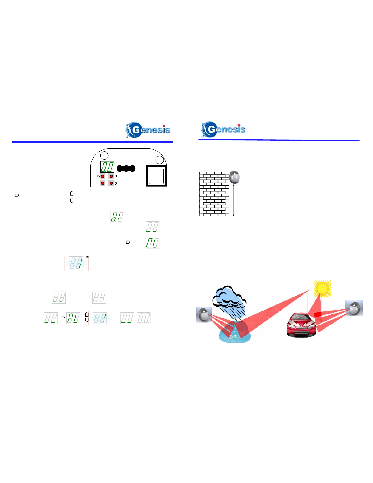
PROGRAMMING:
The new version 2 model now has an
LED display and push buttons to set
the mode of operation.
This makes changing settings much
easier as the buttons and display are
easily located on the top of the mirror.
Button functions.
SELECT UP
M MEMORISE DOWN
Power On,
When the power is turned on, the display shows momentarily.
How to set standard functions.
Step 1. Enter the settings mode press M until the display shows
Step 2. Scroll through mode the options with this button EG:
When the desired mode is reached, wait a moment and then the display will
flash the setting. EG: = pulse count 1.
To change a setting, select the mode and wait for the setting to flash.
Scroll up or down to the desired number.
Step 3. Press and hold the M button to store the new number.
The display shows followed by
Now let go of the button and the new setting is now stored.
EXAMPLE: M
To change more than one setting at a time, follow steps 1 and 2 and after
changing the setting press to select the next mode. Press the M button when all
changes have been made.
NB: The display will automatically turn off after 10 minutes if M is not pressed.
M
TRAN1
LG2 WP-3020 & WP-6004 Wireless PIR Detector Installation Handbook Page 7.
IMPORTANT:
Make sure that the rear tamper magnet has been fitted first using the template before fixing the product in place.
Mounting height
2.5m
To
4m
Mounting height
The correct height for the PIR is 2.5 metres above
the ground, however it can be mounted up to 4 metres but the mirror must be angled down. See
“mirror adjustments”.
Mounting height and positioning.
Minimising false alarms.
Make sure that nothing can move or flutter in front of the detector and avoid facing reflective surfaces. The fixing of the detector must be solid and not sway.
Avoid situations where the detector can overshoot the detection area.
The Genesis 2 detector uses a patented Black Mirror which filters out unwanted
sunlight however it is still good practice to consider the position carefully to minimise the possibility of reflections.
Page 8
LG2 WP-3020 & WP-6004 Wireless PIR Detector Installation Handbook Page 8.
Batteries:
Genesis 2 is supplied with two alkaline 1.5 volt C cells. (MN1400 LR14)
These cells are fitted in BAT1 and BAT2 positions.
To turn the product on, the battery selector jumper must be fitted to the 2x1.5V
position.
If the product is to be used in very cold climates then it is recommended to use
one 3.6 volt lithium C cell (not supplied) instead.
(Recommended EVE ER26500)
This battery must be fitted to the BAT1 position.
In this instance, the two alkaline batteries must be removed and the battery
selector jumper fitted to the 1x3.6V (BAT1) position.
NB: The battery selector jumper is used to turn the detector on as well as select
between one 3.6 volt battery or two 1.5 volt batteries.
The jumper must be removed if the product is to be powered from an external
source.
External power supply:
This product can be powered from an external 12 volt DC supply instead of batteries. Remove the battery selector jumper and the alkaline batteries.
NB: If batteries are left in the product for many years, they may leak and damage the circuit board.
Cable entry is via the IP66 rubber grommets at the rear of the detector, or the
cable entrance at the bottom of the detector which is a knockout for a 20mm
cable gland.
2 x 1.5V
1 x 3.6V
(BAT1)
2 x 1.5V
1 x 3.6V
(BAT1)
ON
2 x 1.5V
1 x 3.6V
(BAT1)
OFF
ON
2 x 1.5V
1 x 3.6V
(BAT1)
OFF
LG2 WP-3020 & WP-6004 Wireless PIR Detector Installation Handbook Page 9.
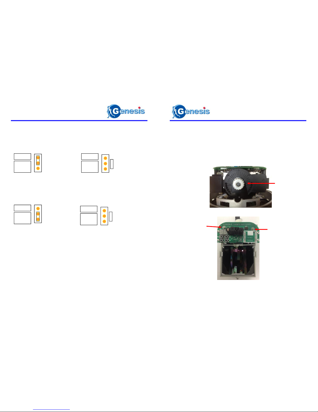
Mirror adjustments:
If the mirror assembly was removed, re-fit it now.
Horizontal Left / Right adjustment is achieved by slackening the knurled white
thumb screw and rotating the mirror assembly click by click in 10 degree steps to
the required position. The degrees –90 0 +90 are shown in the picture.
Fine adjustment from –5 to +5 degrees is achieved by rotating the Fine Adjust
screw either clockwise or anti-clockwise.
Vertical Up / Down adjustment is achieved by adjusting the white plastic screw
as shown.
Aim the mirror in the direction you wish to protect and tighten the horizontal
course adjust screw.
It is not normally required that the mirror be tilted up or down and it should be
left in the neutral 0 deg position.
Horizontal Fine Adjust.
Vertical Adjust
Mirror tilt.
+ 5 deg
0 deg
-5 deg
-10 deg
-15 deg
Top view
Horizontal
Coarse Adjust
–90 +90 degrees
 Loading...