

Page 1
Australian Owned, Designed and Manufactured
Genesis Electronics Australia Pty Ltd
www.genesiselectronics.com.au
[email protected]
Genesis reserves the right to change or modify products without notice.
This manual assumes installers of this product are professionals within
the electronic security, access control and automation industry. As such,
knowledge of these industries on the part of the installer is assumed.
Genesis takes no responsibility for any damage, financial loss or injury
caused to any equipment, property or persons resulting from the correct
or incorrect use of any Genesis devices.
Distributed By:-
32 Output Controller
GEN-050
TECHNICAL MANUAL
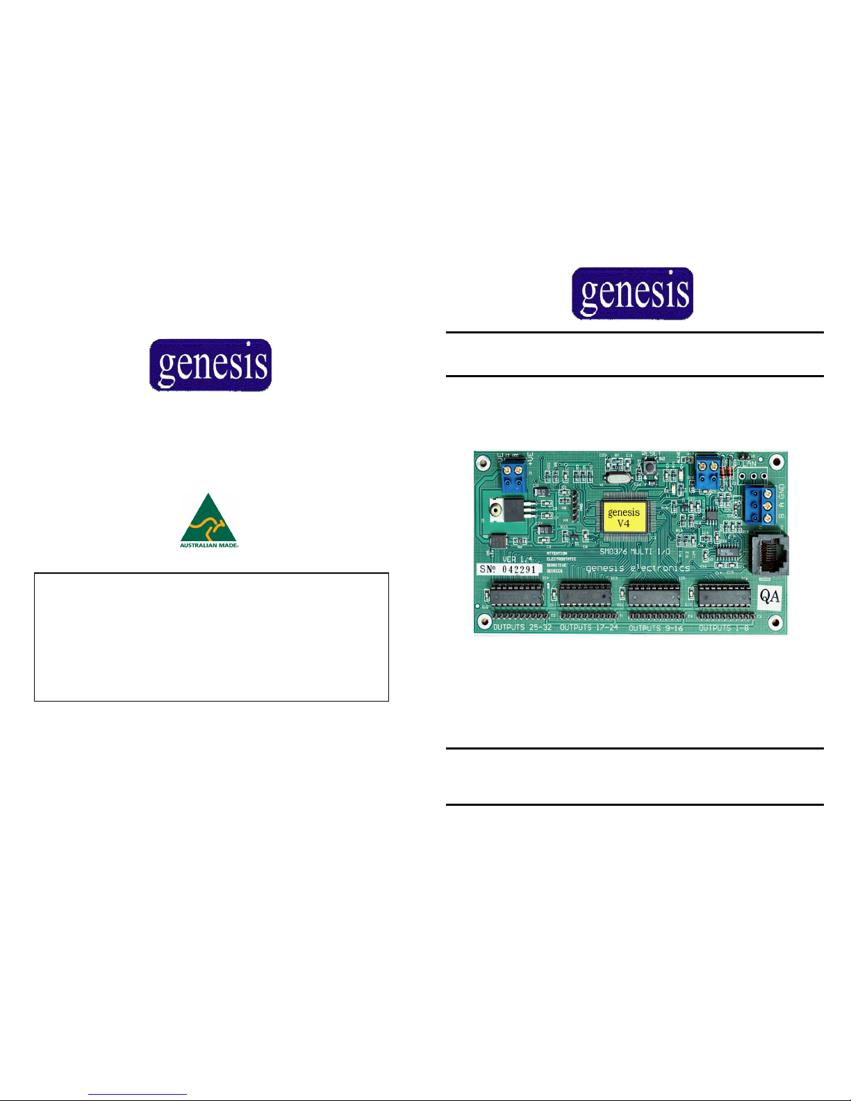
…The very latest innovation in security and access
genesis
V4 – O/C Manual, November 2005
Revision - 1.0
Genesis Electronics Australia Pty Ltd
www.genesiselectronics.com.au
[email protected]
Page 2

genesis 32-Output Controller - Technical Manual
Page 2 V4, O/C Manual – Nov 2005
Table of Contents
TABLE OF CONTENTS 2
PARTS CHECKLIST 3
SPECIFICATIONS 4
FEATURES AND BENEFITS 5
OC MODULE LAYOUT 6/7
OPEN COLLECTOR CONNECTION 8
MOUNTING 9
GENESIS LAN 10/11
POINTS TO NOTE 12
OUTPUT LOCATION CAHART 13
genesis 32-Output Controller - Technical Manual
Page 15 V4, O/C Manual– Nov 2005
NOTES
Page 3
genesis 32-Output Controller - Technical Manual
Page 14 V4, O/C Manual – Nov 2005
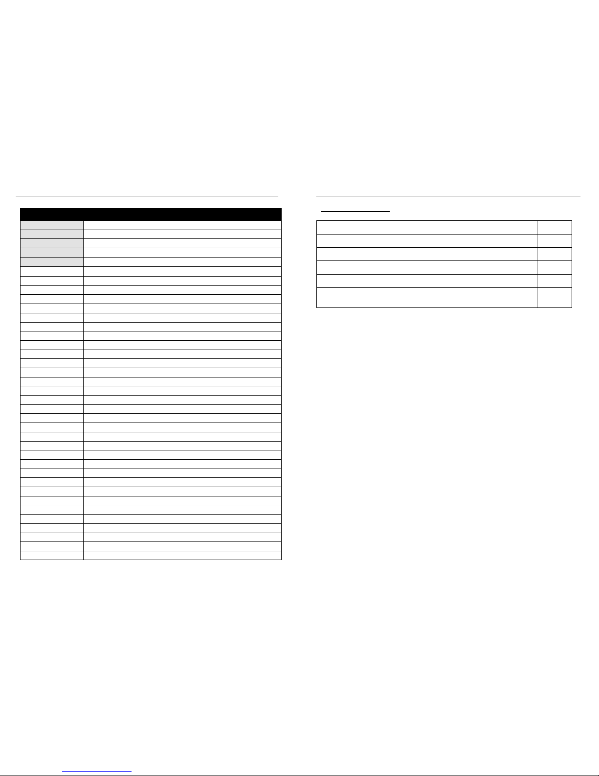
Serial number
Address
Location
Install date
Script
Output 1
2
3
4
5
6
7
8
9
10
11
12
13
14
15
16
17
18
19
20
21
22
23
24
25
26
27
28
29
30
31
32
Device: Output Information
genesis 32-Output Controller - Technical Manual
Page 3 V4, O/C Manual– Nov 2005
Parts Checklist:
1 x 32 Output Open Collector Module (GEN-050)
□
2 x 2 pin terminal block
□
1 x 3 pin terminal block
□
1 x 2 pin jumper
□
4 x mounting screws (M3 x 10mm
□
1 x 32 Output Open Collector Module – Technical Manual
(this manual)
□
Page 4
genesis 32-Output Controller - Technical Manual
Page 4 V4, O/C Manual – Nov 2005
Caution: All Genesis devices are electrostatic sensitive devices. As such, all care
should be taken to ensure appropriate procedures are in place when
handling and installing Genesis devices. This may include, but is not
limited to wearing an appropriately earthed, conductive wrist strap – to
limit electrostatic discharge into Genesis devices.
Dimensions (H x W x D): 140 x 80x 30 mm
Input Voltage: 11-16v DC
Standby Current Draw: 30mA
Processor: 16 bit microprocessor
Memory: 256k ROM and 20k RAM
Inputs
1 x tamper monitoring
Outputs
32 x open collector outputs
Specifications:
genesis 32-Output Controller - Technical Manual
Page 13 V4, O/C Manual– Nov 2005
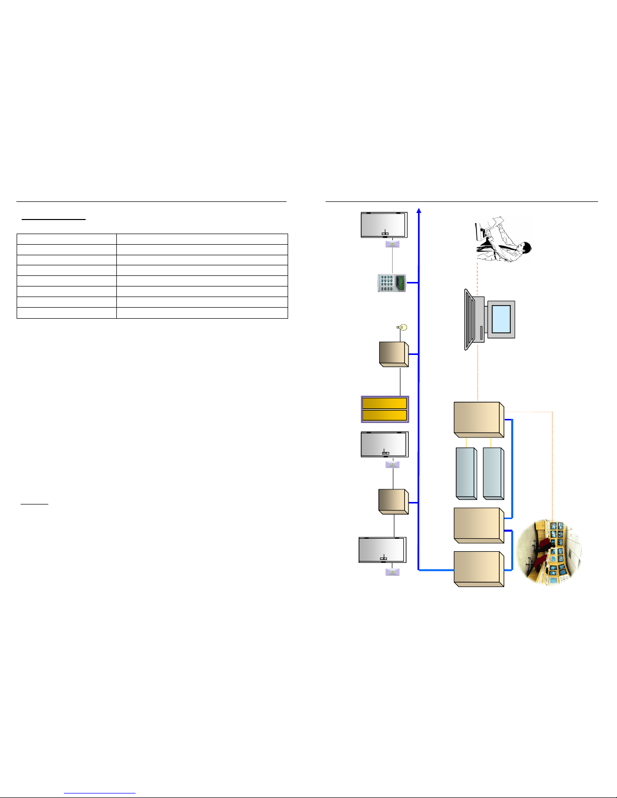
System Layout
O/C, 32-Output Controllers, for
Automation, Lift Control, Door Con-
trol, up to 512 Outputs
Up to 127 LAN Device modules on RS485 2-wire LAN
GENIE user interface software include, Client database
management, full review of Access / Alarm events, all
events time date stamped, print out reports, arm / disarm
GENIE
interface
Electric
Lock
Reader
GEN-001
Master
Panel
16 /32 Inputs
4/8 Outputs
1Amp Power
GSM Dialler
backup
STU-232
Serial Securitel
Reader
Electric
Lock
Reader
Electric
Lock
Lifts Control
Lighting
Automation
LAN, extends up to 1500m
Report Printer
TDC, 2-Door Controllers
Up-to 128 Access doors
RAS, Remote Access
Station
Up-to 96 RAS
2-wire LAN
PSTN line Dialler or SECURITEL Monitoring
GEN-025
EU8
8-Input
Expander
GEN-010
Expander
unit
16 /32 Inputs
4/8 Outputs
1Amp Power
Supply
O/C TDC
Page 5

genesis 32-Output Controller - Technical Manual
Page 12 V4, O/C Manual – Nov 2005
Points to Note:
• It is recommended to use a separate power supply, located near the
32 Output Open Collector Module. DO NOT common the 0v DC,
or +12v DC, of power supplies and Genesis devices.
• Connection to the output pins on the 32 Output Open Collector
Module is best made using a 10 pin header socket. These headers
are used on the GEN-060 relay module, and are the preferable way
to connect to the 32 Output Open Collector Module. Genesis does
NOT recommend soldering cable to the output pins. Connection
in this manner will void warranty.
• Removal of the Serial Number from any Genesis device will im-
mediately void any warranty applicable to it, or any interconnected
Genesis device.
• Caution: The 32 Output Open Collector Module is only capable
of sinking 100mA max through each output. Excessive current
draw will damage the 32 Output Open Collector Module.
• Caution: When connecting GEN-060 Relay Output Modules to
the 32 Output Open Collector Module, please note that each
• GEN-060 can draw up to 300mA in current. Low voltage alarms
may be generated if the devices draw more current than the power
supply is capable of supplying.
genesis 32-Output Controller - Technical Manual
Page 5 V4, O/C Manual– Nov 2005
Features and Benefits:
The Genesis 32 Output Open Collector Module (OC) is a dedicated output device that communicates with the Genesis master unit via high
speed RS-485 LAN communication. O/C provides 32 programmable
open collector outputs, on the one device.
The 32 Output Open Collector Module mounts easily within the standard Genesis metal equipment cabinet, and includes an external tamper
input to provide maximum protection.
The 32 Output Open Collector Module supports up to 4 x Genesis relay
boards (GEN-060), which quickly and easily provide dry contacts for
switching high current, or multiple voltage loads.
With this functionality, the 32 Output Open Collector Module is ideal
for controlling; lifts, automatic doors, lighting, solenoids, indicators,
mimic panels, additional relays and LED’s.
The 32 Output Open Collector Module is particularly useful in building
automation and home automation applications.
Up to 512 outputs are supported within a Genesis system, with as few as
16 x 32 Output Open collector modules required for this function.
Page 6
genesis 32-Output Controller - Technical Manual
Page 6 V4, O/C Manual – Nov 2005
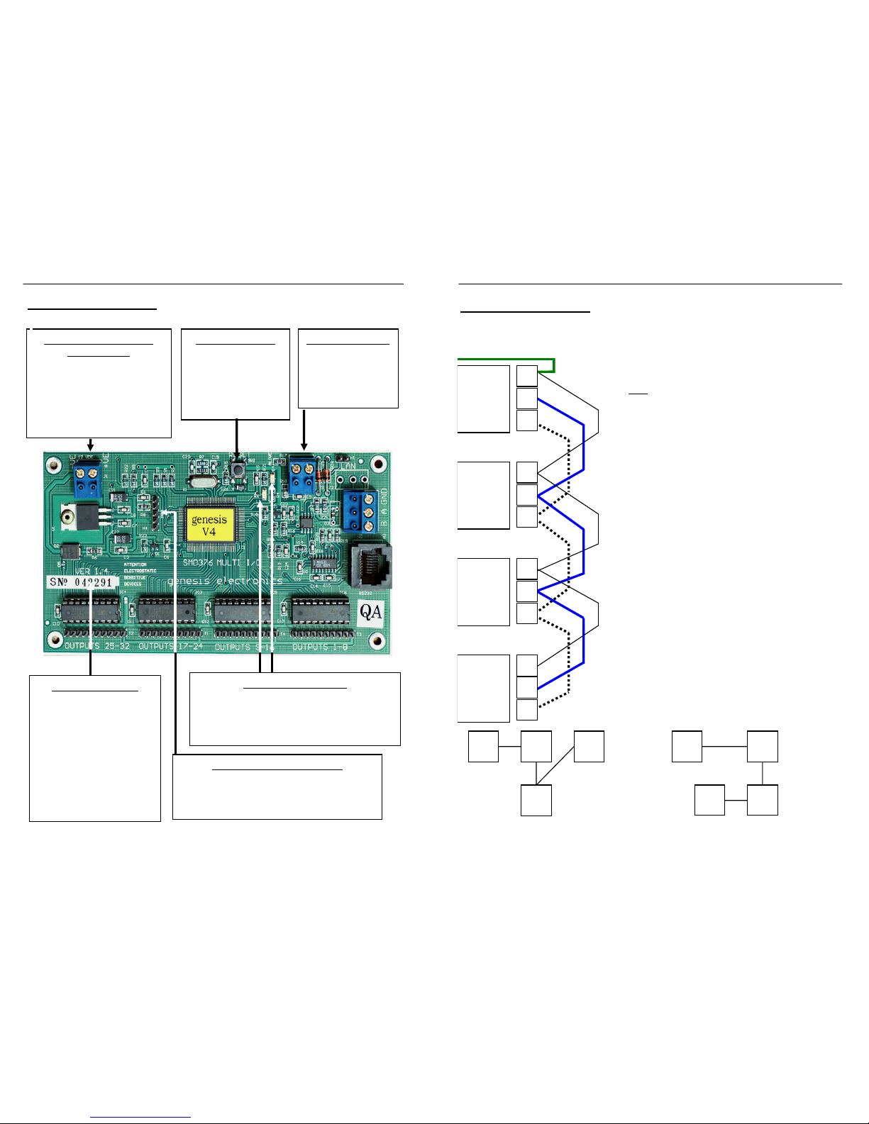
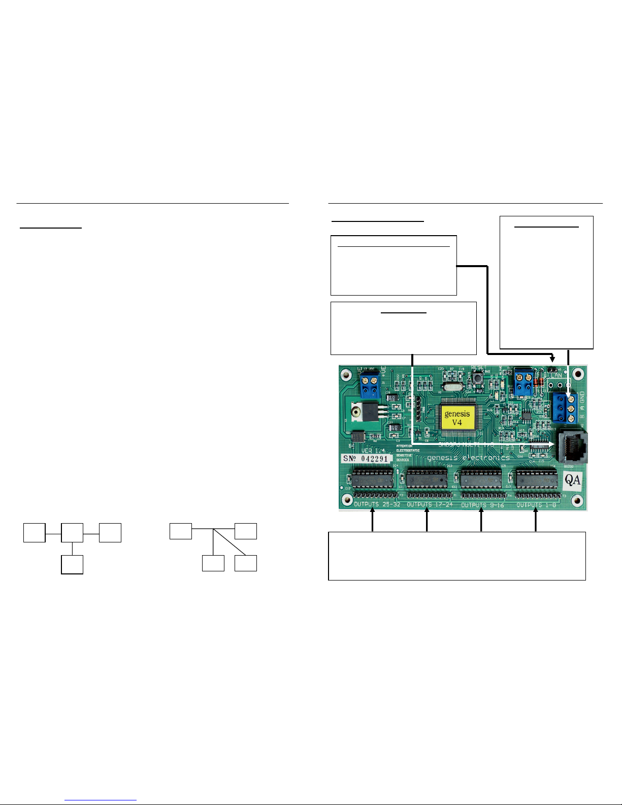
12v DC POWER INPUT
TERMINALS
Supplied for connection of
12v DC to power the module.
Genesis recommends only
using factory recommended
power supplies with Genesis
devices.
RESET BUTTON
Used when generating
a hardware reset to
the device processor.
Use only under in-
struction from your
TAMPER INPUT:
Provided to allow
normally closed
connection of a
cabinet tamper to
this device.
SERIAL NUMBER
Each Genesis device is
fitted with it’s own unique
Serial Number. This number will need to be entered
into the Genesis Master
Unit, via the technician
software, before the device
will come on line.
Removal of the Serial Num-
ber will void Warranty
ALIVE and RX LED’s
Provides a quick indication as to system status.
Flashing ALIVE LED = Device Processor OK.
Flashing RX LED = LAN Comms OK
PROGRAMMING HEADER
The programming header is supplied to allow
easy flash upgrading for any future features.
Please contact your distributor for more de-
O/C Module Layout:
genesis 32-Output Controller - Technical Manual
Page 11 V4, O/C Manual– Nov 2005
The Master Unit must always be the first device on the LAN. This device is factory fitted
with a 180Ω LAN Termination Resistor.
The shield from the LAN cable should run the
length of the LAN, and should be connected to
a communications earth, at the Master Unit
only
.
The shield terminals on each device are for
connection of shield cables, and do not connect to the device proper in any way
Up to 127 additional Genesis devices in total
can be connected to the Genesis LAN, across
a total LAN length of up to 1500 meters.
The last device on the Genesis LAN must be
fitted with its termination link. This link fits a
180Ω resistor to the last device on the LAN.
No other devices should have a termination
link fitted. If connected as described above,
the LAN should have an impedance of approximately 90Ω, plus the resistance of the LAN
cable. *
Don’t test LAN impedance with any devices powered up.
Ensure the cable shield is not connected to
any ground or to any voltage on any device
and that the cable shield is only connected to a
communications earth at the Master .
Genesis LAN (cont.):
Correct LAN configuration Correct LAN Configuration
Master Unit
GEN001
Remote
Access
Station
GEN030
Expander
Unit
GEN010
Two Door
Controller
GEN045
A
Connect to Communications Earth
B
A
SHD
B
A
SHD
B
A
SHD
B
SHD
Page 7
genesis 32-Output Controller - Technical Manual
Page 10 V4, O/C Manual – Nov 2005
X X
Improper Star Configuration Improper Tee Off Configuration
Genesis LAN:
Genesis uses industry standard RS-485 LAN communication to ensure fast
efficient network communication between devices. The Genesis LAN operates at a communication speed of 19,200 baud between up to 128 devices
over a total LAN distance of up to 1500 meters.
In order to ensure that a high level of performance is achieved, it is necessary to connect the Genesis LAN in the recommended method.
To this end, it must be twisted pair data cable that is used for the Genesis
LAN. Belden 8723 (RS-485) cable, or equivalent is recommended.
A standard must be applied when wiring from one LAN leg to another. For
example, the A leg on a Master Unit must always be connected to the A legs
on other Genesis devices, while the B leg must always be connected to the B
legs on other Genesis devices.
A very common communication problem is where the A and B lines are reversed.
If this occurs, then some devices may appear on-line, while others are off-line.
The Genesis LAN is an industry standard multi-drop RS-485 configuration.
Do Not Tee Off, or Star configure your LAN. For STAR configuration
please refer to information on GEN-129 4-way LAN distribution module.
While the LAN may function in these configurations, Genesis cannot guarantee proper LAN performance.
genesis 32-Output Controller - Technical Manual
Page 7 V4, O/C Manual– Nov 2005
O/C Module Layout:
H1 – LAN TERMINATION LINK:
The LAN Termination Link should
only be fitted on the last device on the
Genesis LAN. Please refer to page 9
for further information on the Genesis
LAN.
RS-232 PORT
Use to allow connection to PC, or other third
party device communicating with RS-232.
Only available for use if enabled in Genesis
Technician Software.
LAN TERMINALS:
The A and B LAN termi-
nals are designed for the
Genesis LAN to be termi-
nated into. The A and B
lines must always be connected to the A and B ter-
minals on other Genesis
devices. The shield
(SHLD) terminal has been
supplied to secure the cable
shield only. Please refer to
page 9 for further informa-
tion on the Genesis LAN.
32 OPEN COLLECTOR OUTPUTS
Organised into groups of 8, each output is capable of sinking up to
100 mA maximum.
Page 8
genesis 32-Output Controller - Technical Manual
Page 8 V4, O/C Manual – Nov 2005
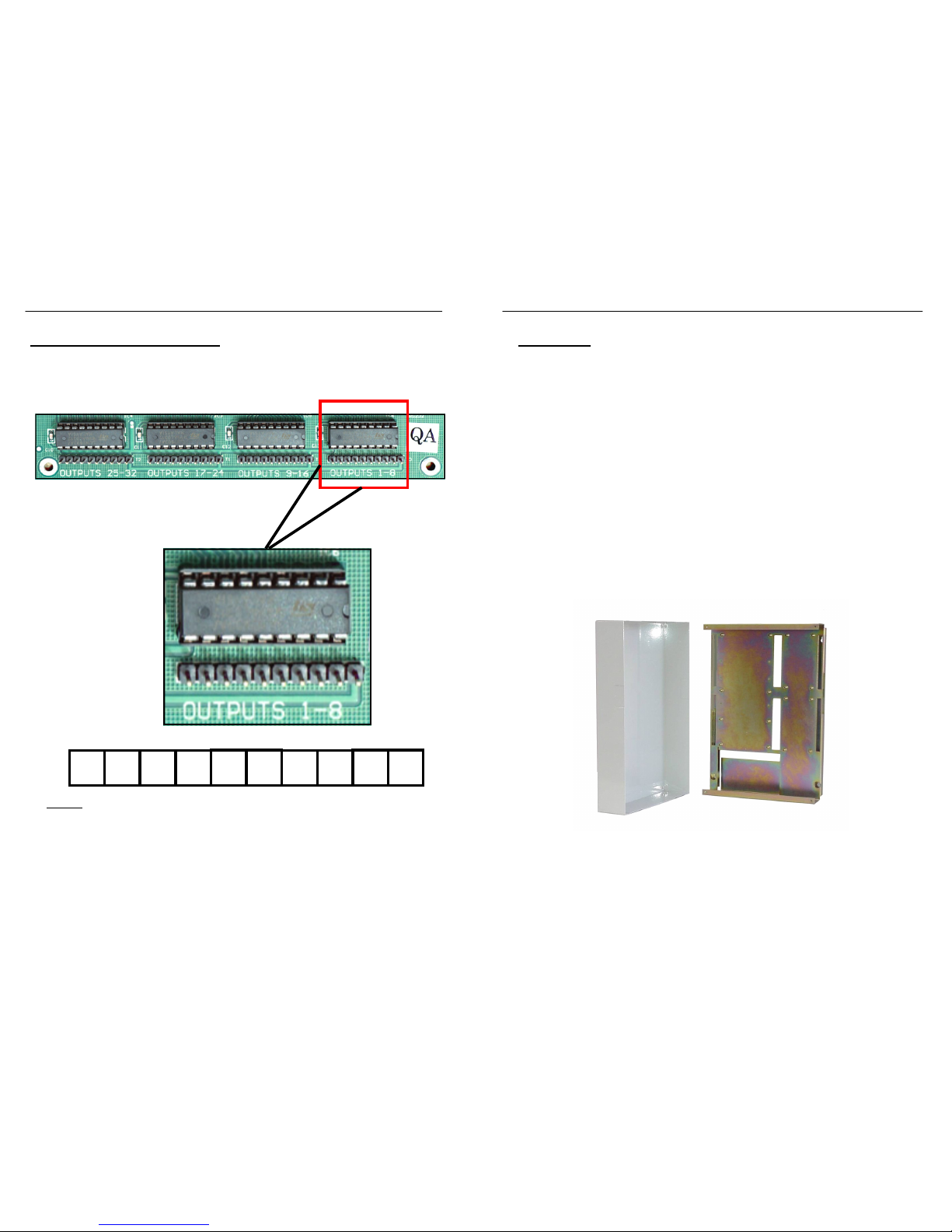
Open Collector Connection:
+12V
DC
OUT
1
OUT
2
OUT
3
OUT
4
OUT
5
OUT
6
OUT
7
OUT
8
OV
DC
NOTE:
Outputs 9-16, 17-24 and 25-32 all use the above format.
0v 32 31 30 29 28 27 26 25 +12v 0v 24 23 22 21 20 19 18 17 +12v
0v 16 15 14 13 12 11 10 9 +12V 0v 8 7 6 5 4 3 2 1 +12V
Each open collector output switches to ground (-ve) when triggered,
and is capable of sinking up to 100 mA, 12v DC.
genesis 32-Output Controller - Technical Manual
Page 9 V4, O/C Manual– Nov 2005
Mounting:
The 32 Output Open Collector Module is designed to mount within the
HDW-001, metal equipment cabinet. Using this cabinet, it is possible
to mount the GEN-050 OC Module, along with up to 4 x GEN-060
Relay Output Modules within the one cabinet, or any other combination of Genesis equipment may also be mounted with 32 Output Open
Collector Module.
The four screws supplied with the 32 Output Open Collector
Module are for securing the controller to the stand-offs on the
HD-001.
Avoid installing the 32 Output Open Collector Module outdoors.
 Loading...