

Page 1

Service Manual
Holtvej 8-10, Høruphav, 6470 Sydals
Telefon: +45 73 15 11 00
Fax: +45 73 15 11 01
E-mail: info@scanmi.dk · www.scanmi.dk
CVR: 27 73 31 07
November 2010
Race 50
Page 2
1
User's operation and maintenance manual for
double-wheel motorcycle RACE 50
Page 3

2
Zhejiang Qianjiang Motorcycle Co., Ltd.
Contents
Contents 2
Preface 4
Documents to be prepared ...................................................................................................................................5
Inspection/adjustment ..........................................................................................................................................6
Inspection and Service of Electrical System 63
I. Battery/ Charging system 67
1.1 Preparation data ...........................................................................................................................................53
1.2 Fault diagnosis.............................................................................................................................................53
1.3 Battery .........................................................................................................................................................71
1.4 Charging system ..........................................................................................................................................72
1.5 Voltage and current regulator....................................................................................................................... 73
1.6 Charge coil of the alternator ........................................................................................................................74
1.7 Disassembly of alternator ............................................................................................................................74
II.
Ignition system 61
2.1 Preparation data ...........................................................................................................................................61
2.2 Fault diagnosis.............................................................................................................................................79
2.3 Ignition system inspection ...........................................................................................................................83
2.4 CDI group .................................................................................................................................................... 84
2.5 Ignition coil..................................................................................................................................................86
2.6 Trigger .........................................................................................................................................................86
III. Startup system 90
3.1 Preparation data ...........................................................................................................................................91
3.2 Fault diagnosis.............................................................................................................................................93
3.3 Start electric machinery ............................................................................................................................... 93
3.4 Start relay..................................................................................................................................................... 96
IV. Bulbs/ switch/instrument 73
4.1 Preparation data ...........................................................................................................................................99
4.2 Fault diagnosis.............................................................................................................................................99
Page 4

3
4.3 Replace the head light bulb..........................................................................................................................99
4.4 Replace bulb of the front turning light.......................................................................................................100
4.5 Disassembly/replace the bulb of the taillight and rear-right turning light .................................................100
4.6 Instrument..................................................................................................................................................101
4.7 Main switch ...............................................................................................................................................101
4.8 Horn ........................................................................................................................................................... 102
4.9 Handle switch ............................................................................................................................................102
Inspection and Service of Chassis 103
V. Brake 80
5.1 Maintenance instruction............................................................................................................................. 107
5.2 Fault diagnosis...........................................................................................................................................108
5.3 Front hydraulic brake................................................................................................................................. 108
5.4 Rear drum brake ........................................................................................................................................110
VI.Body cover 86
VII. Front wheel/ front suspension 90
7.1 Preparation data ......................................................................................................................................... 119
7.2 Fault diagnosis........................................................................................................................................... 119
7.3 Front wheel ................................................................................................................................................ 120
7.4 Steering bar................................................................................................................................................123
7.5 Front fork...................................................................................................................................................124
VIII. Rear wheel/rear suspension 97
8.1 Preparation data .........................................................................................................................................128
8.2 Fault diagnosis...........................................................................................................................................128
8.3 Real wheel .................................................................................................................................................129
8.4Rear shock absorber.................................................................................................................................... 130
IX. Fuel tank/seat mat 136
9.1 Preparation data .........................................................................................................................................136
9.2 Fault diagnosis...........................................................................................................................................136
9.3 Fuel tank/seat mat......................................................................................................................................137
Inspection and maintenance of engine 139
X. Lubrication system 107
10.1 Preparation data .......................................................................................................................................143
10.2 Fault diagnosis.........................................................................................................................................144
10.3 Oil pump .................................................................................................................................................. 144
XI. Carburetor 111
11.1 Preparation data .......................................................................................................................................149
11.2 Fault diagnosis.........................................................................................................................................150
11.3 Disassembly of carburetor ....................................................................................................................... 150
11.4 Installation & adjustment......................................................................................................................... 155
XII. Cylinder cover 116
12.1 Preparation data .......................................................................................................................................157
12.2 Fault diagnosis.........................................................................................................................................157
12.3 Cylinder head........................................................................................................................................... 157
12.4 Examination on cylinder head .................................................................................................................159
12.5 Cylinder head installation ........................................................................................................................ 159
XIII. Air cylinder/piston 120
Page 5

4
13.1 Preparation data .......................................................................................................................................162
13.2 Fault diagnosis.........................................................................................................................................163
13.3 Cylinder body ..........................................................................................................................................163
13.4 Piston .......................................................................................................................................................165
13.5 Installation of piston ................................................................................................................................170
XIV. Drive disk/Clutch/Driven Wheel / Foot start mechanism 174
14.1 Preparation data .......................................................................................................................................174
14.2 Fault diagnosis.........................................................................................................................................174
14.3 Left crankcase cover................................................................................................................................ 175
14.4 Drive disk.................................................................................................................................................175
14.5 Clutch/driven wheel................................................................................................................................. 178
14.6 Disassemble the clutch and the driven wheel .......................................................................................... 180
14.7 Installation ...............................................................................................................................................186
14.8 Foot start mechanism...............................................................................................................................186
XV. Decelerator 137
15.1 Preparation data .......................................................................................................................................189
15.2 Fault diagnosis.........................................................................................................................................189
15.3 Gear Case................................................................................................................................................. 189
15.4 Installation ...............................................................................................................................................191
XVI. Crankcase 140
16.1 Preparation data .......................................................................................................................................194
16.2 Fault diagnosis.........................................................................................................................................195
16.3 Crankcase................................................................................................................................................. 195
16.4 Installation ...............................................................................................................................................199
Exhaust emission system inspection and maintenance 144
XVII. Exhaust emission and control system 145
17.1 Warranty of Exhaust emission and control system.................................................................................. 201
17.2 Regular maintenance guideline................................................................................................................ 202
17.3 Mechanical function of the exhaust control system.................................................................................203
17.4 Catalyst converter system ........................................................................................................................205
17.5Countermeasure of idle speed emission exceeding specified value(Two -stroke)................................ 206
Page 6

5
Preface
This Manual explains the maintenance of Qianjiang RACE 50.
The documents to be prepared are the maintenance manual and all the operations are included in, please read
the manual prior to operation.
Inspection and Adjustment explains the gist of inspection and adjustment; the maintenance of safety of vehicle
and the performance of each part should come into force since regular inspection.
After Chapter I is the explanation of the gist of disassembly, assembly and inspection of engine, entire vehicle
and electric fittings.
There are exploded view, system diagram, maintenance, fault diagnosis and explanation before each chapter.
Notice:
There is no prior individual notification on the alteration of mode or structure of motorcycle and the actual
product shall prevail if there is discrepancy between the photos, pictures or explanation contained in this Manual
and the actual product.
Zhejiang Qianjiang Motorcycle Co., Ltd.
Page 7

6
Documents to be prepared
General safety Maintenance regulation
Specififcation sheet Troubleshooting
General safety
Carbon monoxide
If the engine must be activated, make sure that the workplace is well ventilated. The engine can not be running in a
confined place.
Attention
The exhaust contains toxic gas, carbon monoxide, which can numb people and may result in death.
The engine should be started in an open area and the exhaust scavenging system should be applied if the engine has
to be started in a closed area.
Gasoline
The operation should be made in a ventilated area and smoking or lighting fires should be strictly forbidden in
working space or the place stored gasoline.
Battery
Battery could give off explosive gases, so, keep it away from incineration area or open flame or where smoking is
permissible. When charging, keep it well-ventilated.
Battery contains sulphuric acid (electrolyte) which could result in burn if contacting your skin or eye, so, wear
protective clothing and faceshield.
-If electrolyte spatters on your skin, use fresh water to flush immediately.
-If electrolyte spatters in your eye, use fresh water to flush for more than 15 minutes and see a doctor
immediately.
Electrolyte is toxic. In case you drink some electrolyte inadvertently, drink a large volume of fresh water, milk and
milk of magnesia (a kind of laxative antiacid) or vegetable oil and see a doctor immediately. Keep it at a place
where is beyond reach of children.
Page 8
7
Maintenance regulation
As maintaining this vehicle, the instrument of metric system should be applied as possible for the reason that the
application of incorrect instrument may demage this vehicle.
Before dismantling from or frame cover of vehicle to maintain the dirt of parts or external subassembly should be
purged in order to prevent that falling into engine , chasis or braking system.
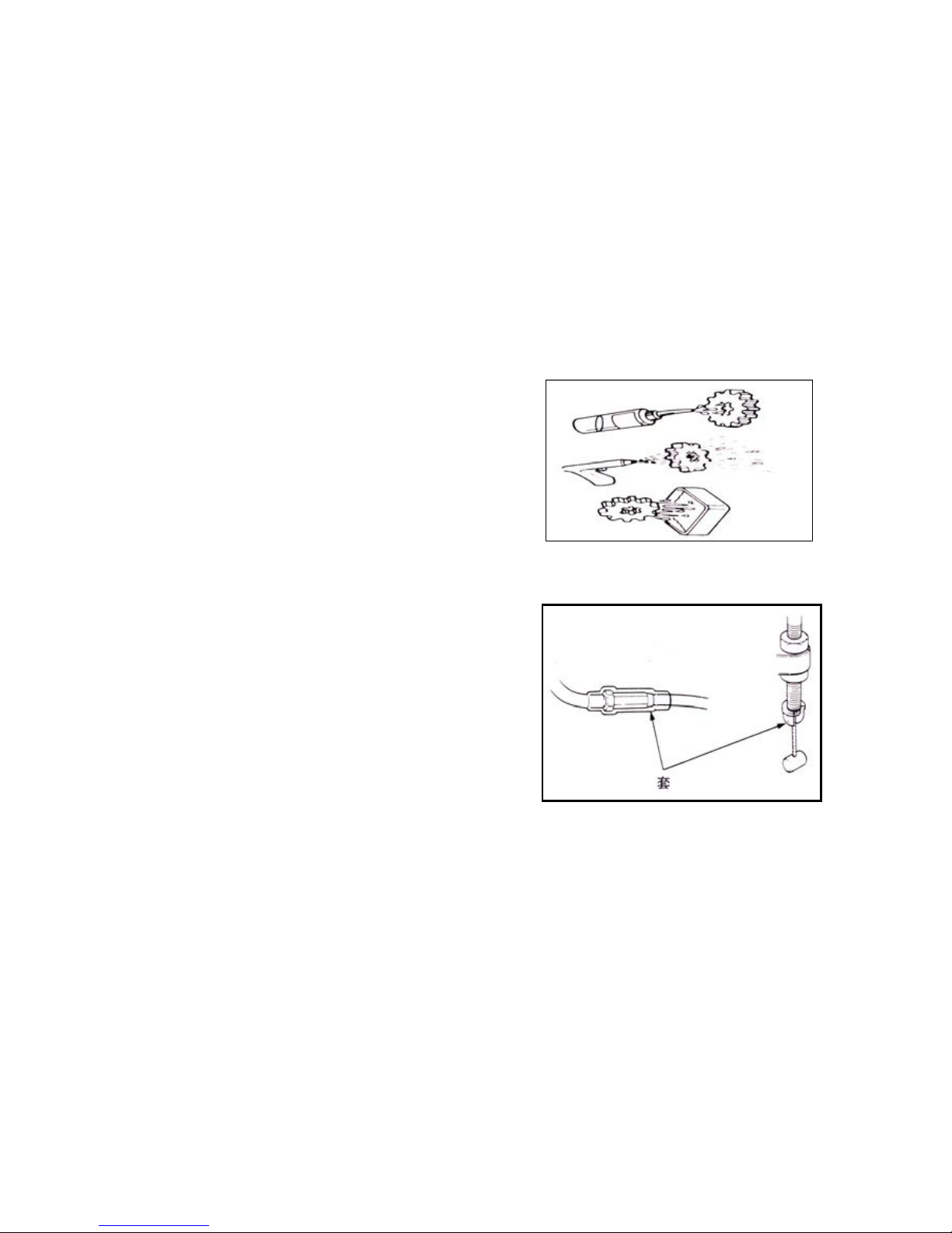
After dismantling and before measuring attrition value, please
clean parts and purge it with compressor.
The rubber parts will be deteriorated due to aging which is prone to be damaged by solvent or oil and it should be
inspected (if necessary, it should be replaced) before
reinstallation.
Sleeve
Page 9

8
Loosen the parts with multiple assemblies that should be made
from outside to inside and started from small one.
The complicated assembly, transmission case, for instance, should
be stored according to proper assembly sequence in order to
facilitate the assembly in the future.
Page 10
9
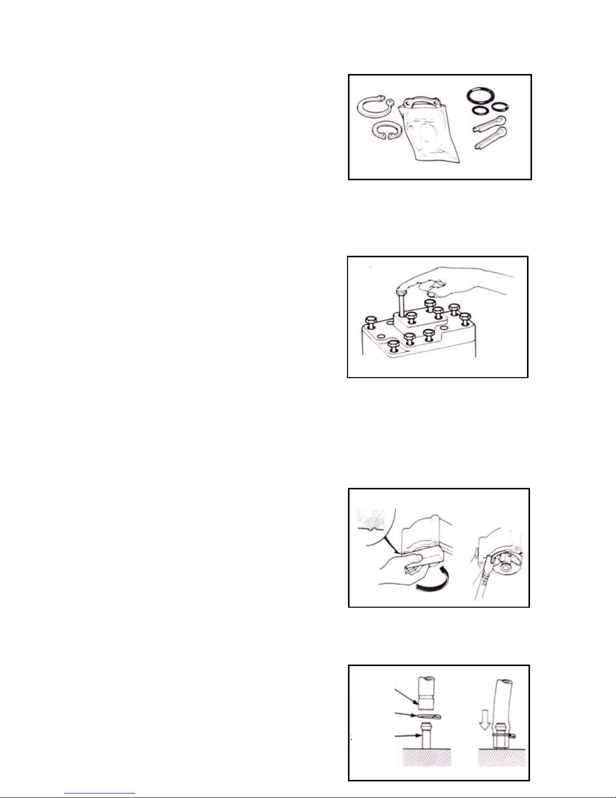
For the important assembly position, it should be given special
attention before dismantling. The parts out of use should be
replaced before dismantling in time.
The length of bolts to assemblies and frame cover are different
which should be installed in correct position and the bolts may
placed in the hole to find out whether they are suitable if they are
mixed.
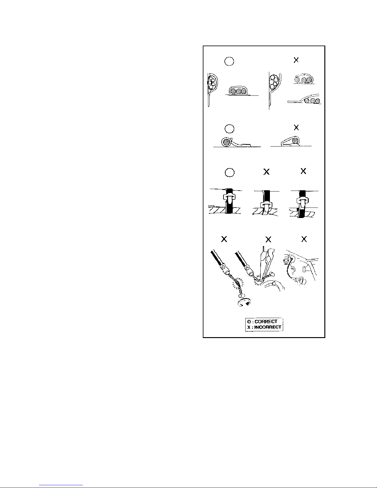
For the installation of oil seal, the grease should be filled in oil
seal groove; as installing oil seal, it should check the smoothness
of oil seal whether it will likely damage the oil seal.
For the installation of rubber hose (fuel, vacuum or coolant), the
ends of which should plug into the bottom of the joint in order to
ensure that there is enough space for hose clamp to clamp the
joint. The rubber or plastic soldering cup should restore its
Grove
Clamp
Joint
Page 11
10
original design position.
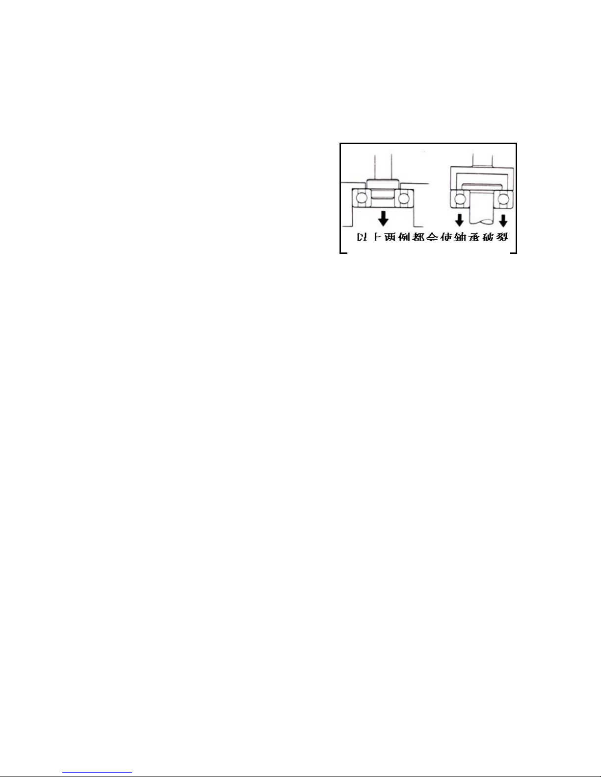
As dismantling ball bearing, please use the tool to withstand one
or two (internal and external) bearing runners. If the strength is
only applied onto a rolling ring (no matter internal or external),
the bearing may be damaged as dismantling and has to be
replaced.
In both instances, the bearings will be broken
Page 12
11
Loose cable is a hidden trouble to electrical safety. After
clamped, check each cable to ensure electrical safety;
It is not allowed to leave any wire clip bending towards
bonding points;
Bind each cable to its designated position;
It is not allowed to lay a cable to end or a sharp corner on
frame;
It is not allowed to lay a cable to end of a bolt or screw;
When laying a cable, keep it away from any heat source or
any place where may bite it when it is moving;
When laying a cable along a handle, avoid it being strained
too tightly or loosely and it can not interfere with any
adjacent part at any turning point;
All cables should be laid smoothly without twist or knot;
Before butt-jointing a connector, check if its sheath has been
damaged and if it is overstretched;
If a cable is at a sharp corner or outer corner, use tape or hose
to protect it;
After a cable is repaired, use tape to bind it securely;
Keep all control cables from bend or twist because dumb
control will result in case any control cable is damaged.
Page 13
12
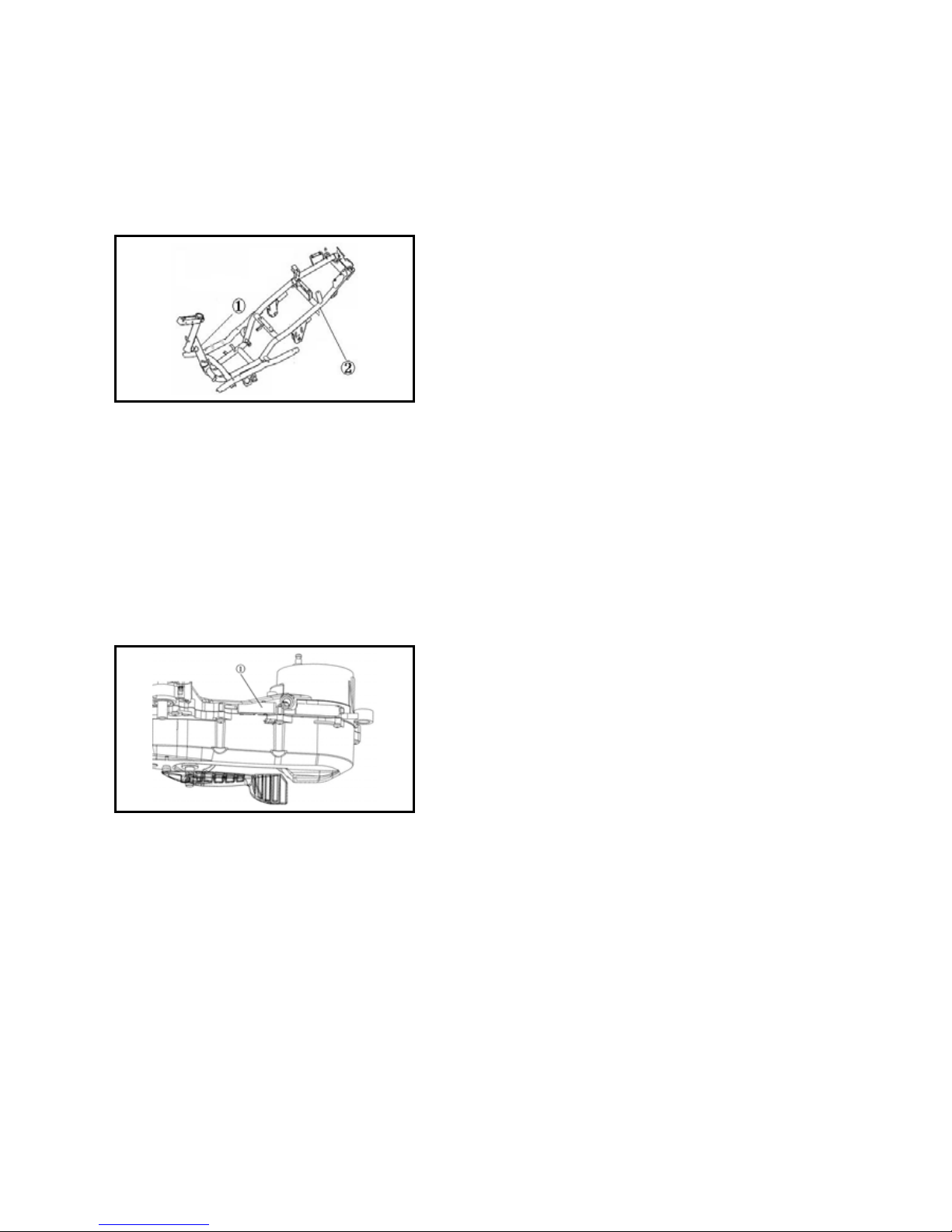
Motorcycle Identification
1. The vehicle identification number (VIN) is inscribed at
① on the frame. See Figure 1-1. Identification number:
LBBB9212?????????. On the VIN, the 10
th
digit shows the year
of manufacture and the 11
th
digit shows the code of the
manufacture plant. The anti-refit name plate is stuck inside the
helmet bucket; the frame name plate is riveted to ② on the
frame.
Figure 1-1
2. The engine series number ① is inscribed on the
crankcase housing. See Figure 1-2.
Figure 1-2
Important Notices
1. Please use genuine parts of Qianjiang Motorcycle. Use of the parts that fail the design specifications of
Qianjiang Motorcycle may cause damage to engine.
Page 14

13
2. During servicing, use metric tools only. Do not interchange a metric bolt, nut or screw and an English system
fastener.
3. During reassembly, replace with new washers, O-rings, cotter pins and locking pieces.
4. When tightening bolts or nuts, tighten the ones with larger diameters or comparatively located at inside first, and
then tighten all bolts or nuts diagonally to specified torques step by step unless described otherwise.
5. Clean the removed parts with washing fluid. Before assembly, lubricate all sliding planes.
6. After assembly, check all parts for proper installation and correct operation.
7. Before measurement, remove dirt and oil; during assembly, add recommended lubricants to oil sites.
8. When engine and driveline require a long-term storage after dismounted, please apply lubricant to surfaces of
parts to prevent rust and dust accumulation.
Page 15
14
Specific tools
The so-called specific tools refer to those specifically designed for assemble or dismantle of certain
components of the motorcycle. These tools are usually used in specific locations. Appropriate specific tools are
indispensable in the complete and accurate adjustment as well as in the assembly operations. By taking advantage
of specific tools, the components can be safely, reliably and quickly assemble or dismantle, thus enhancing the
work efficiency and saving lots of efforts.
1.tools used for the engine-overhaul
When assembling or dismantling the engine, specifically designed tools should be used for some certain
components to guarantee a smooth dismounting.
The list of specific tools for the assembly and dismantling of engine components and the figure of real objects
can be seen in table 1-1 and table 1-2.
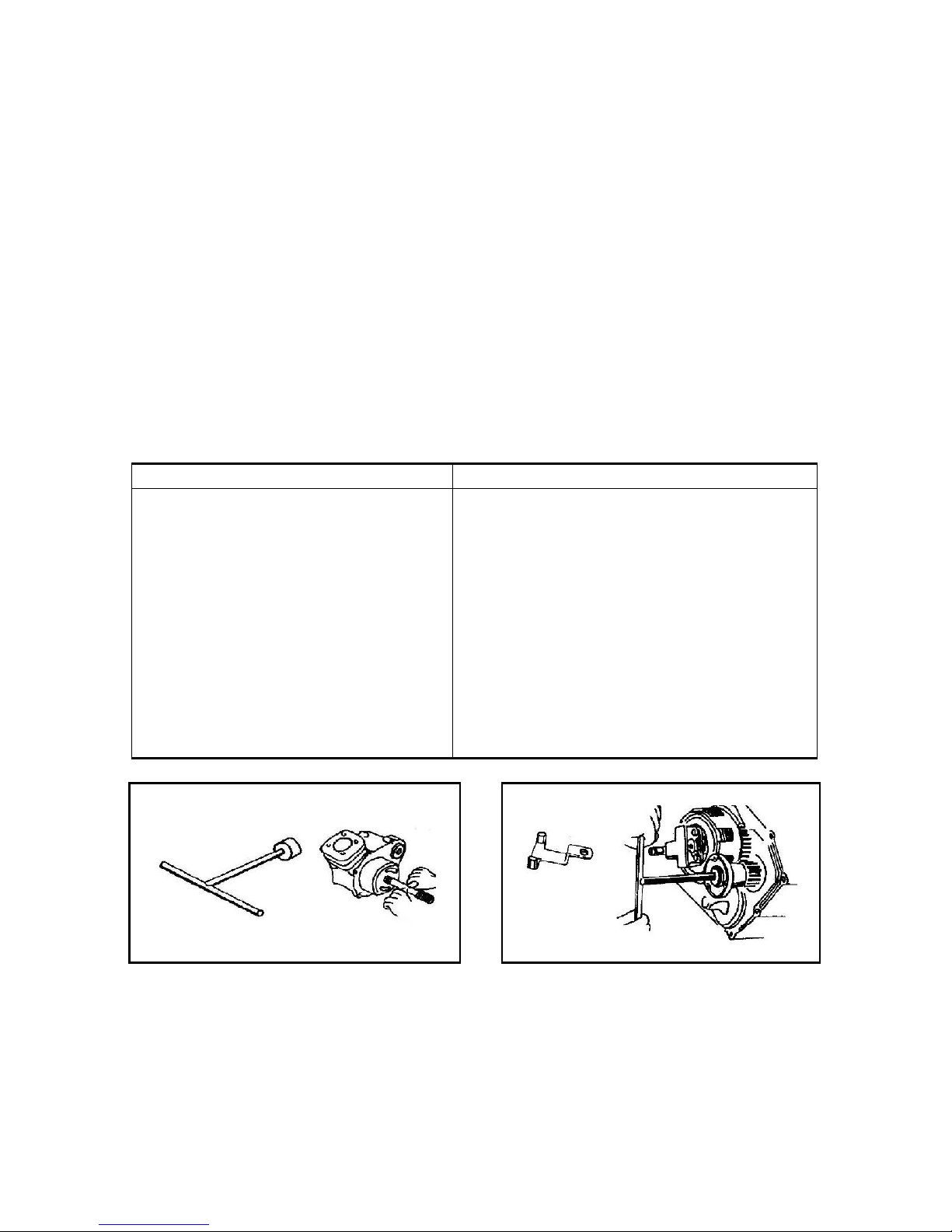
Table 1-1
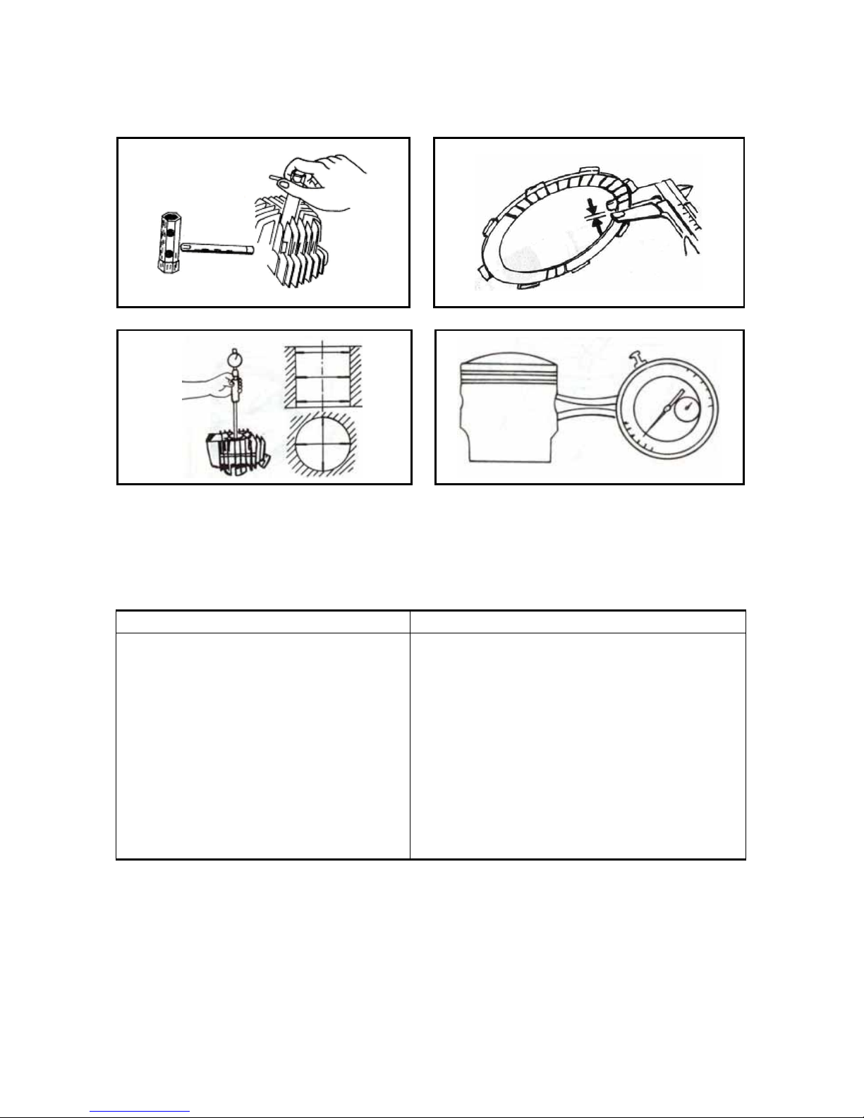
Name Remarks
Specialized circular wrench
Clutch holder
Flywheel extractor
Spacer gauge
Dismounting tools for bearing
Assembling tools for bearing
Oil-seal dismounting tool
Handle of dismounting tools
Piston pin exhaustion apparatus
Piston ring opening pincer
Heating plug circular wrench
Measure the thickness of clutch
Cylinder diameter tester
Dial dictator
Used for the assembly and dismantle of flywheel
bolt ,figure 1-3
Figure 1-4
Figure 1-5
Figure 1-6
Figure 1-7
Figure 1-8
Figure 1-9
Figure 1-10
Figure 1-11
Figure 1-12
Figure 1-13
Figure 1-14
Figure 1-15
Measure the inner canon of piston pin,Figure 1-16
Successive table 1-2
Figure 1-3 Figure 1-4
Page 16
15
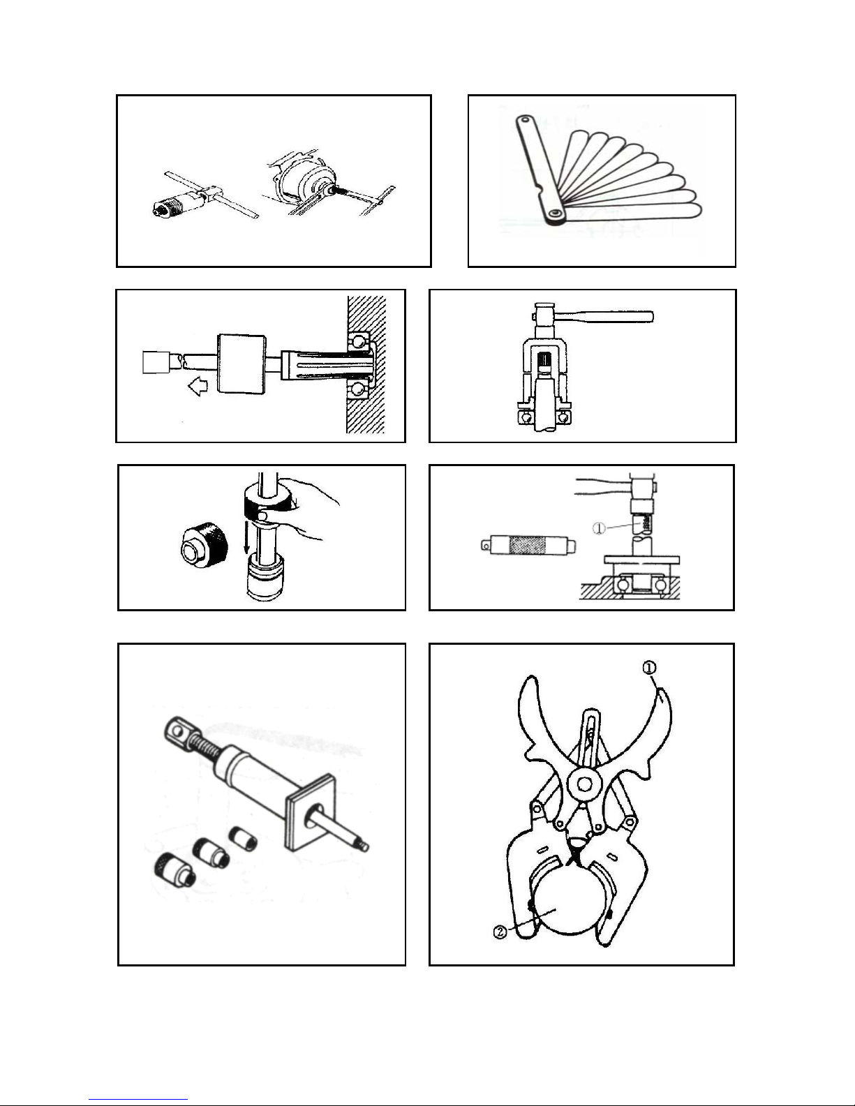
Figure 1-5 Figure 1-6
Figure 1-7 Figure 1-8
Figure 1-9 Figure 1-10
①Handle
Figure 1-11 Figure 1-12
Thickness gauge (clearance gauge)
Page 17
16
① opening pincer ② piston
Figure 1-13 Figure 1-14
Figure 1-15 Figure 1-16
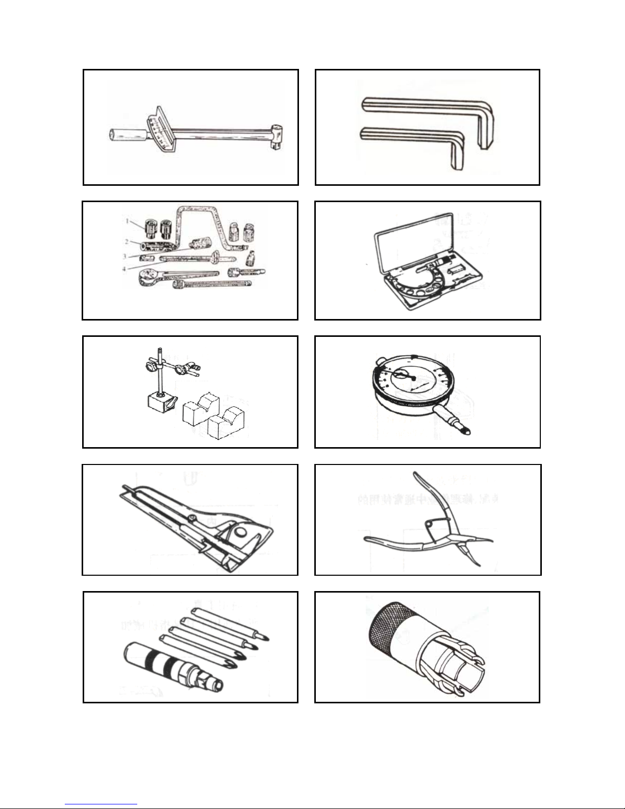
2.Tools used for the underpan-overhaul
The list of general tolls and specific tools for the dismounting of underpan components as well as the figure of
real objects can be seen in table 1-17 and table 1-18.
Figure 1-17
Name Remarks
rest wrench
inner hexagon wrench
circular wrench
micrometer
magnetic stand, V-shape block
dial indicator
square caliper
spring clip-ring clipper
whack-type screw drive
front fork oil seal dismounting tools
front part seal element driving-in tools
steering nut wrench
Figure 1-19
Figure 1-20
Figure 1-21
Figure 1-22
Figure 1-23
Figure 1-24
Figure 1-25
Figure 1-26
Figure 1-27
Figure 1-28
Figure 1-29
Figure 1-30
(1)General tools for the underpan-overhaul
Successive table 1-18
Page 18
17
Figure 1-19 Figure 1-20
Figure 1-21 Figure 1-22
Figure 1-23 Figure 1-24
Figure 1-25 Figure 1-26
Figure 1-27 Figure 1-28
1. Bush-head 2.Shake-handle
3.Ratchet type wrench 4.Connecting-rod
Page 19
18
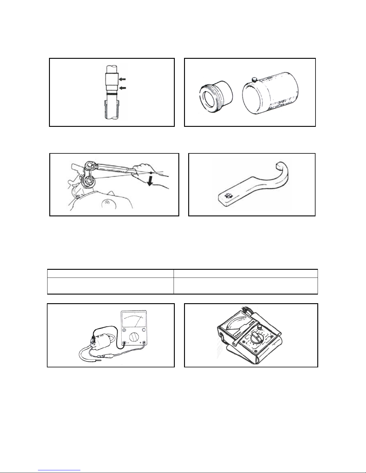
(2)Specific tools for underpan-overhaul: front fork seal element driving-in tools
Figure 1-29
(3)Steering nut wrench
Figure 1-30
3.Tools used for electric apparatus components
The list of specific tools for the testing of electric apparatus components, as well as the figure of real objects
can be seen in table 1-31 and table 1-32.
Table 1- 3 1
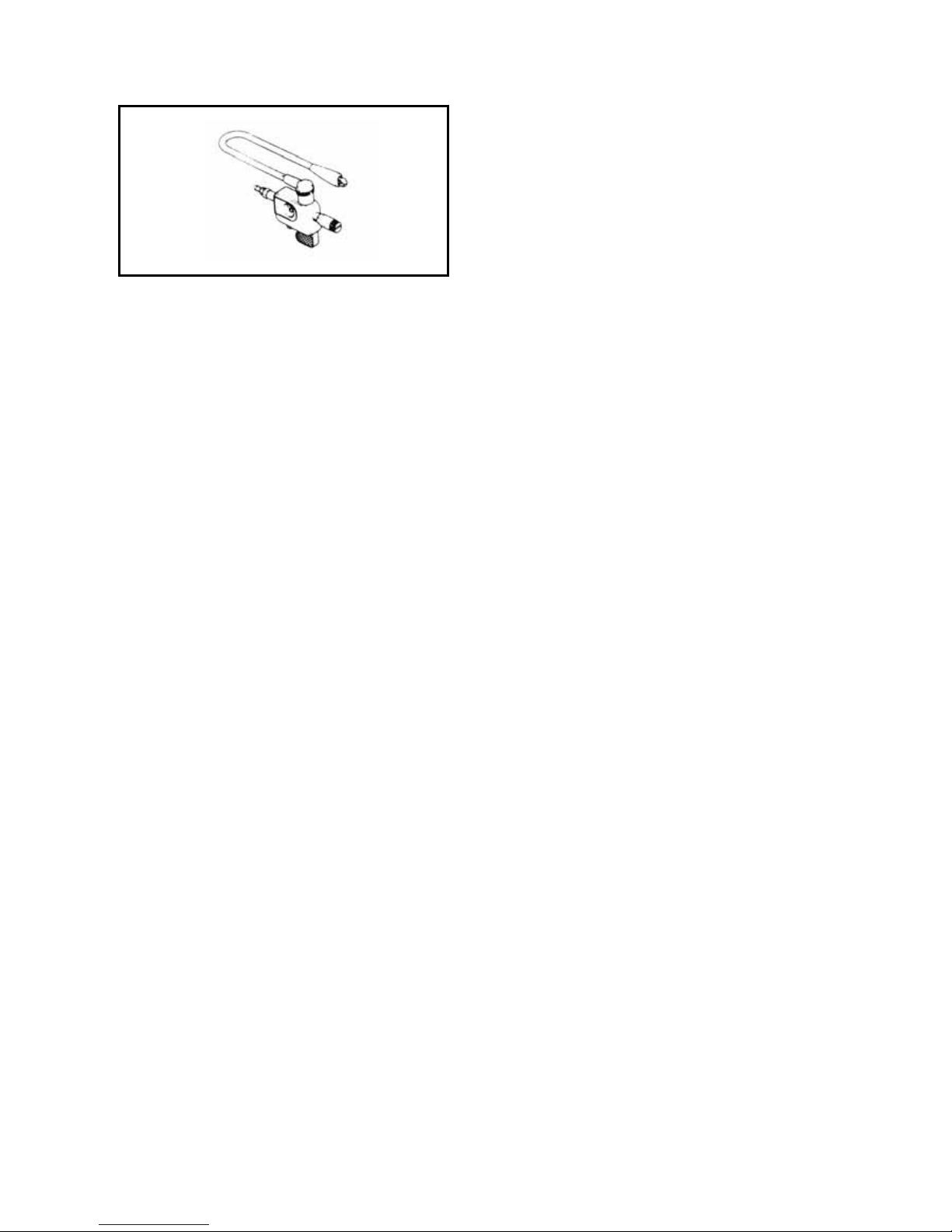
Name Remarks
universal meter
ignition tester
Figure 1-33
Figure 1-34
Successive table 1-32
Figure 1-33
Page 20
19
Figure 1-34
Page 21
20
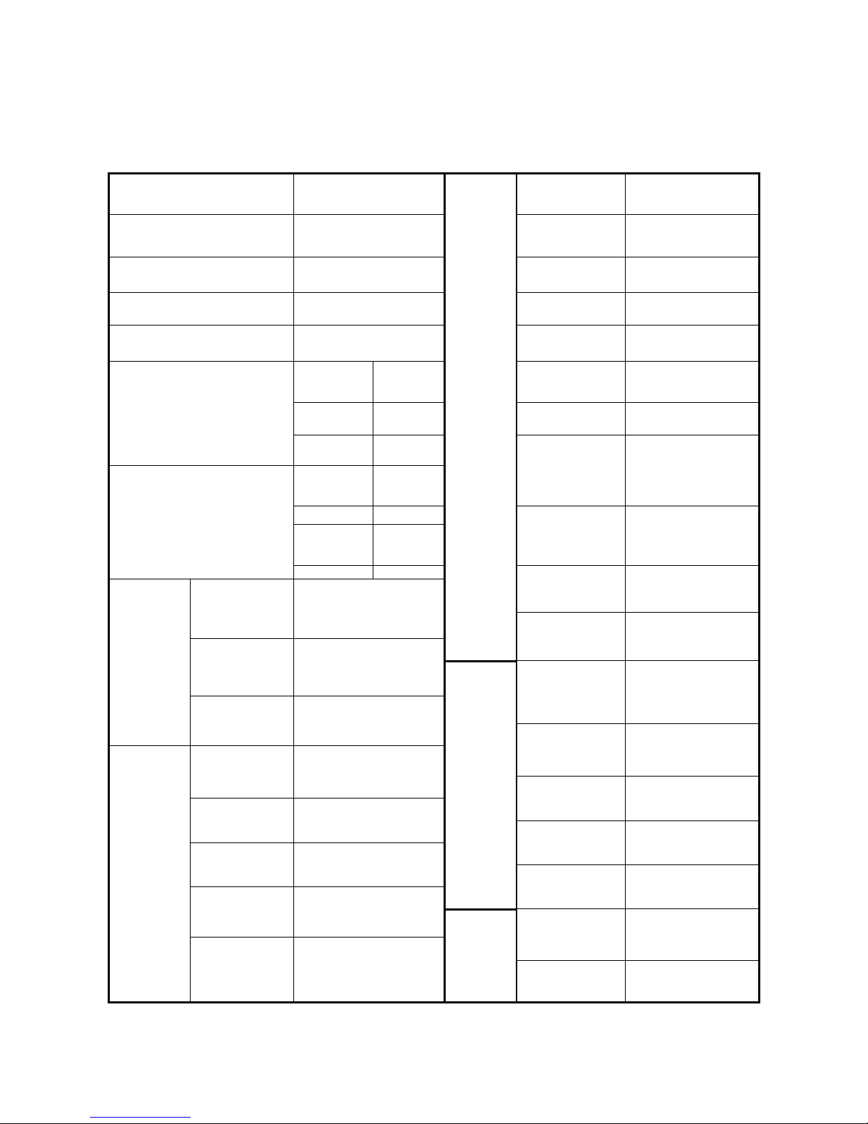
Specififcation Sheet (RACE 50)
Model RACE 50 Engine Type QJ1E40QMB-4
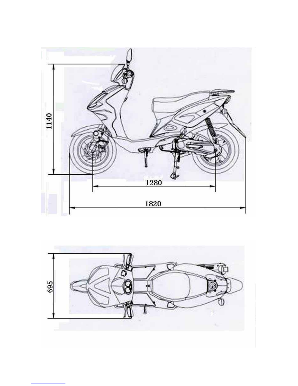
Full length mm 1820 Fuel type
Unleaded gasoline
(92/95)
Full width mm 695
Number of
cylinders
1
Full height mm 1140
Inside measure
* stroke
40×39.2
Wheelbase mm 1280 Total flow rate 49.2
Front axle 37 Start mode
Start by electricity
Foot start
mechanism
Rear axle 55 Cooling mode Wind-cooling
Vehicle weight kg
(serving quality)
To ta l
92
Outer
cover of
front wheel
120/70-12
Lubrication
Lubricate
separatly
Front rim
3.50×12
Outer
cover of
rear wheel
130/70-12
Air cleaner
3XG
Tyre specification
Rear rim 3.50×12
Petrol capacity 5±0.2L
Clutch type
Dry-centrifugal type
Engine
Carburetor type IIF-45
Transmission Stepless shift
Idling speed -
rpm
1750±100rpm/min
Gearing
Driving mode Belt drive
Maximum
torque
4.3 N.m/5500rpm
Battery
capacity/type
12V-4AH/
dry-charged type
Maximum
torque
2.50kW/6000 rpm
Capacity of
alternator
90W/8000rpm
Compression
ratio
6.9:1
Spark plug
NGK/TORCH,
BR7ES
Perform
ance
Maximum speed 45km/h
Spark plug 0.6-0.7mm
Diameter of
front brake
disk(mm)
φ190mm
Electrical
installation
Ignition mode CDI
Brake
Inner diameter
of rear brake
drum
(mm)
φ110mm
Page 22
21
RACE 50
Page 23

22
Page 24
23
N Y
N Y
Y N
Y N
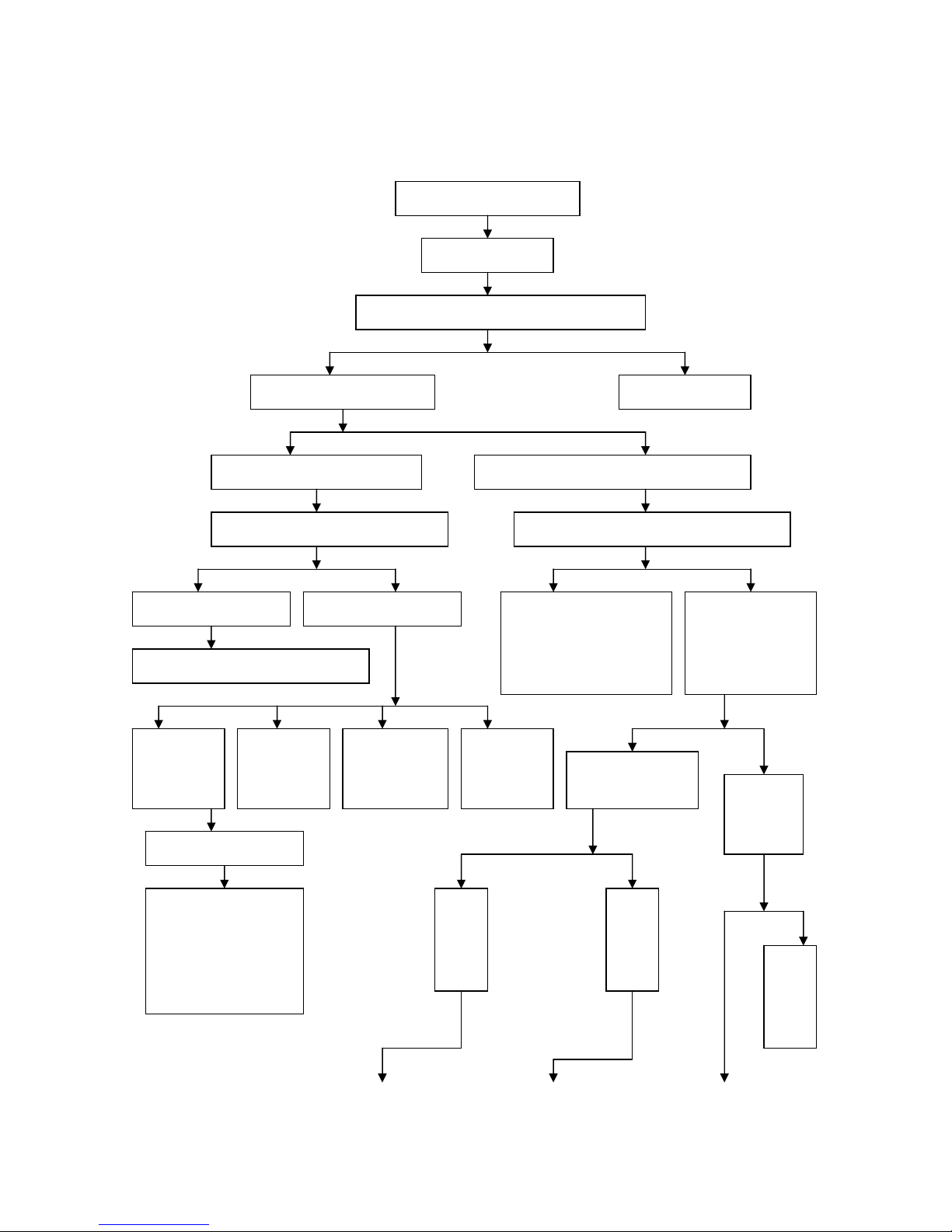
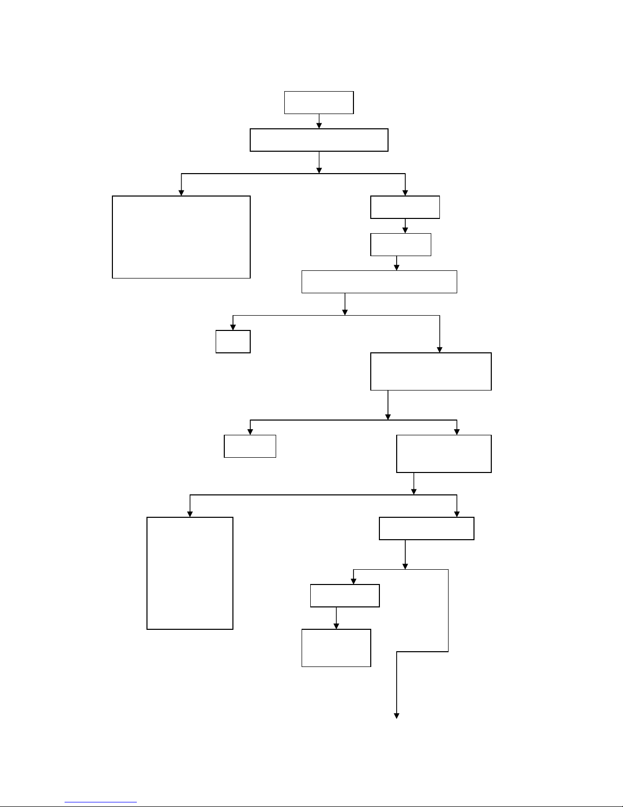
Troubleshooting
Trouble diagnosis program for engine start failure or difficulty
Engine fails or is difficult to
start
Check ignition
s
y
ste
m
Remove spark plug to check between its
electrodes for carbon connection
Perform spark over test of
s
p
ark plug
Clear carbon deposit
Sparks between electrodes weak or
none at all
Strong blue or purple blue sparks can jump out
from between electrodes
Screw off spark plug cap to perform
s
p
ark over test of ignition coil
Use an ignition timing light to detect if engine
i
g
nition timing is correct
Strong blue sparks can
jump
out
Sparks weak or none at
all
Check spark plug and its cap for
malfunction
Check
supply of
ignition
power
Check
ignition coil
for short
circuit or
open circuit
Check internal
wiring of
ignition system
for short circuit
or open circuit
Check CDI
igniter for
malfunction
Use a cylinder
pressure gauge to
check and measure
com
p
ression
Check
inside of
fuel tank
for
presence
of
Com
press
ion
press
ure
of
cylin
Com
press
ion
press
ure
of
cylin
Fill
gasol
ine
No-contact magneto
i
g
nition system
1. Check ignition power
coil for short circuit or
open circuit
2. Check trigger coil for
short circuit or open
circuit
1. Check CDI igniter for
malfunction
2. Check magneto flywheel
and trigger coil for
looseness
Loosen drain screw
on carburetor to
check if gasoline
flows out from
overflow pipe on
carburetor
Page 25
24
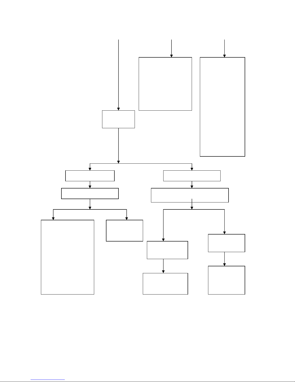
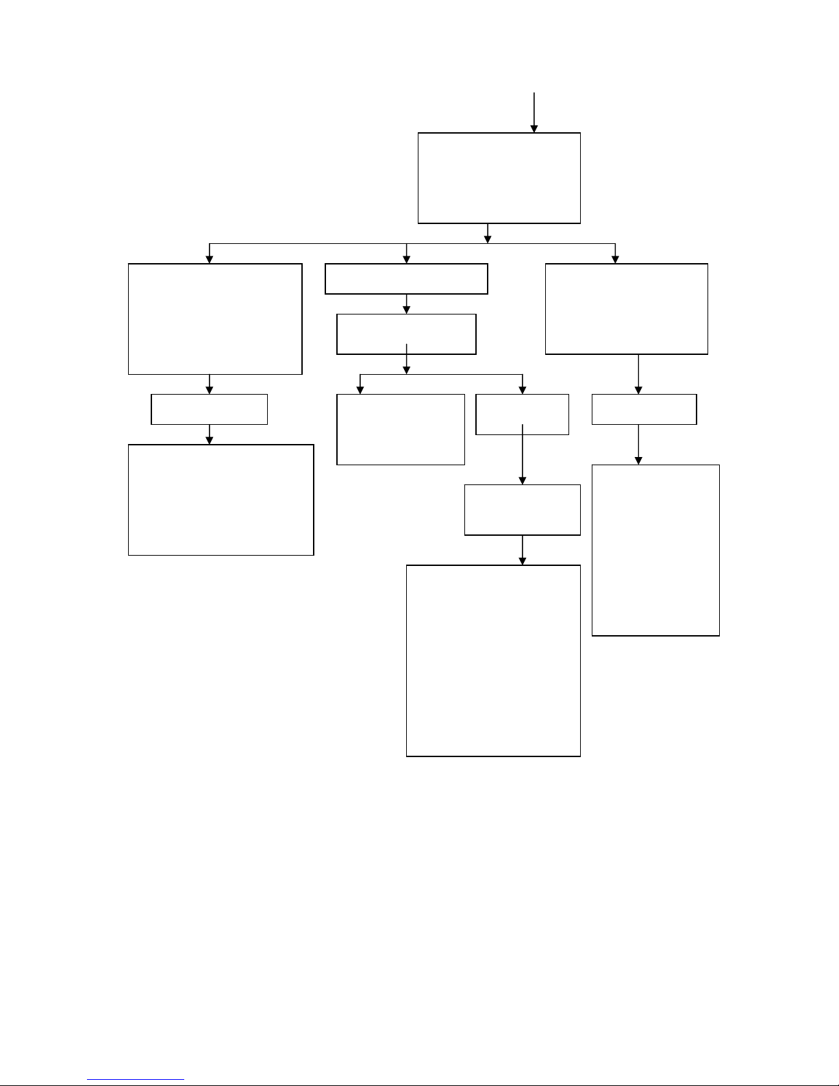
Y N
Spark plug electrode wet Spark plug electrode dry
Check carburetor for flooding
Drip a little gasoline into cylinder to
perform experimental starting
1. Check between needle
valve and valve seat of
carburetor float for ajar
position caused by foreign
materials
2. Check cone of float
needle valve of carburetor
for steps caused by wear
3. Check for broken
carburetor float
4. Check carburetor float
for insufficient height
Check air cleaner
for clogging
Engine shuts down
in a very short time
after start
Engine can
continue to work
after start
Inside of carburetor
clogged or float
height excessive
Carburetor
starting device
(i.e. starting
richer system)
malfunctioning
1. Check all joints outside
engine for air leak
2. Check for the piston ring
locked in groove or having
insufficient elastic force
3. Check piston ring and
cylinder for wear
1. Check breather on
fuel tank cap for
clogging
2. Check fuel filter and
fuel cock for clogging
3. Check fuel cock for
proper operation
4. Check oil inlet on
carburetor for clogging
5. Check carburetor
float for height excess
Remove spark
plug for
inspection
Page 26
25
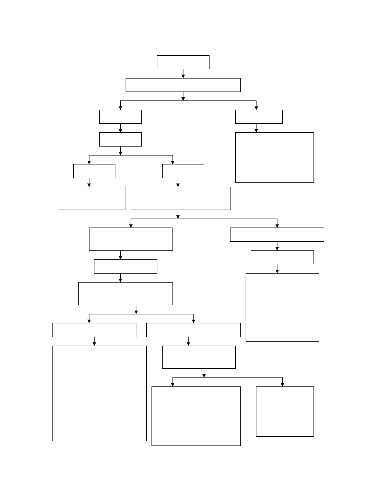
Y N
Y N
Y N
N Y
Y N
Trouble diagnosis program for engine overheat
Engine
overheats
Check for improper method of
o
p
eration and usage
1. Check gasoline for inferior
brand or extended storage
2. Check if engine has ever run at
high speed or worked under
overload during running
Check cooling
s
y
ste
m
Air cooling
en
g
ine
Check radiating fins for sticking mud
and sand or excessive oil stains
Clea
n
Check cooling fan and its
cowl for damage (forced air
cooling engine)
Check and
troublesho
Use an ignition timing
light to detect if engine
ignition timing is
correct
1. Check CDI
igniter for
malfunction
2. Check magneto
flywheel and trigger
coil for looseness
Check for clutch slip
Clutch slips
Refer to
handling of
clutch slip
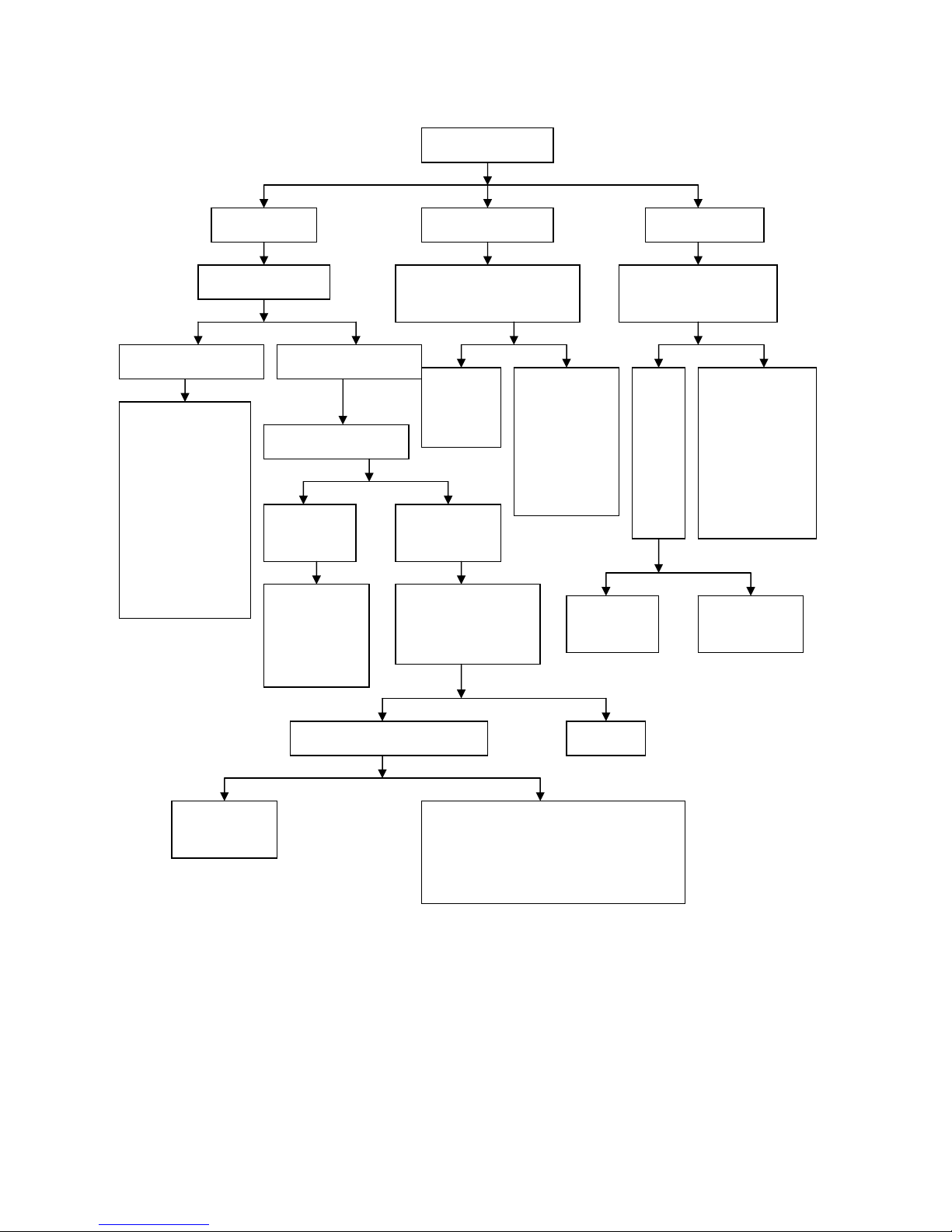
Page 27
26
Remove spark plug, observe
color of spark plug insulator
skirt and determine mixture
ratio of combustible mixture
according to various abnormal
situations.
Spark plug insulator skirt
renders black; in addition,
exhaust muffler gives off black
fume or blasts, accelerating
ability is poor or idle speed is
instable and engine is liable to
shutdown when it is running
under medium low speed
(comparatively normal when it is
Spark plug insulator skirt
renders chocolate-
b
rown
Spark plug insulator skirt
renders white; in addition,
intermittent engine stop,
carburetor backfire, or power
lack of engine, etc. occurs
during acceleration.
Combustible
mixture too rich
1. Check air cleaner for clogging
2. Check carburetor starting device
(i.e. starting richer system) for
proper operation
3. Check carburetor float for
insufficient height
Mixture ratio of
combustible mixture
normal
Check exhaust port of
cylinder block and
exhaust muffler for
clogging caused by
excessive carbon
de
p
osit
Check
lubrication
s
y
ste
m
Combustible
mixture too thin
Lubrication system
on 2/4 stroke engine
1. Check fuel cock for
proper operation
2. Check carburetor
float for height excess
3. Check all orifices
and tunnels on
carburetor for clogging
1. Check if volume of engine oil
in crankcase is sufficient
2. Check if viscosity of engine
oil in crankcase is too low or
engine oil is too dirty
3. Check oil filter for clogging
4. Check oil pump for proper
operation
5. Check lubricant ducts for
clogging
Page 28
27
Y N
Trouble diagnosis program for engine power lack
Engine power lacks
Erect main jiffy stand to enable wheels to be lifted
off
g
round and then rotate them by han
d
Wheels rotate
freel
y
Wheels rotate
dull
y
Check tire
p
ressure
1. Check brake for retard
2. Check wheel bearing for
excessive wear or damage
3. Check for missing or
comparatively short intermediate
spacer of wheel hub
Air pressure
too low
Air pressure
normal
Check tire valve core for air
leak and check for pierced
or cracked tire
Remove spark plug, block its threaded
hole by finger, and then depress start
button or rapidly depress starting lever.
Fingers feel that gas dashes out
making “pow…pow” sounds
Fingers do not feel that gas dashes out
Compression pressure of
c
y
linder normal
Compression pressure of
c
y
linder insufficient
1. Check all joints outside
engine for air leak
2. Check for the piston ring
broken or locked in groove or
having insufficient elastic
force
3. Check piston ring and
cylinder for wear
Start engine, increase throttle opening
slowly and observe for speed change of
engine
Engine speed rises with increase of
throttle o
p
ening
Engine speed can not rise with increase
of throttle o
p
enin
g
Use an ignition timing light to
detect if engine ignition
timing is correct
1. Check for clutch slip
2. Check drive belt for excessive wear
3. Check centrifugal rollers on head
pulley for excessive wear
4. Check cones on driving wheels and
moving friction wheels for excessive
wear or grooves caused by wear
5. Check cones on driven wheels and
moving driven wheels for excessive
wear or grooves caused by wear
6. Check raceway on inner end face of
moving friction wheel for excessive
wear or pits caused by extrusion
1. Check fuel supply system for
unobstructed fuel supply
2. Check carburetor, air cleaner and
exhaust muffler for clogging
3. Check vacuum diaphragm on
plunger valve of carburetor for map
cracking or breakage
4. Check carburetor float for
improper height
1. Check CDI igniter
for malfunction
2. Check magneto
flywheel and trigger
coil for looseness
Page 29
28
Y N Y N
N Y
Y N
Y
N
Trouble diagnosis program for poor engine idle speed
Engine idle speed is
poor
Engine idle speed
too hi
g
h
Engine idle
s
p
eed disable
d
Engine idle speed
unstable
Check compression
p
ressure of cylinder
Pull carburetor throttle valve
by hand to check if it has been
completely closed
Use an ignition timing
light to detect if engine
ignition timing is correct
Compression pressure
of c
y
linder insufficient
Compression pressure
of c
y
linder normal
1. Check all joints
outside engine for
air leak
2.
5. Check for the
piston ring broken
or locked in groove
or having
insufficient elastic
force
6. Check piston ring
and cylinder for
wear
Readjust idle speed of
carbureto
r
Check for
oversize
idling jet
Check if cable
wire of throttle
control cable
can be pulled
to move
smartly in
cable jacket
and if throttle
valve spring is
too soft
Chec
k for
under
size
clear
ance
betw
een
spark
plug
electr
odes
1. Check CDI
igniter for
malfunction
2. Check magneto
flywheel and
trigger coil for
looseness
Engine idle
speed is
enabled after
ad
j
ustment
Engine idle
speed is still
disabled after
ad
j
ustment
Air adjust
screw on
carburetor or
adjusting screw
on throttle
valve adjusted
improperly
Check idling jet, fuel
way and air way on
carburetor for clogging
Clean and
dred
g
e
Check carburetor float for height
excess
Adjust float
height to
standard value
1. Check insulating body on carburetor for
cracks
2. Check connecting and fixing nut on
carburetor for looseness
3. Check negative pressure pipe of fuel cock
for breakage
4. Check leaf valve for air leak
Adjust
clearance
between
electrodes
Check mixture
ratio of
combustible
mixture
Page 30

29
Y N
Y N
Y N
Y N
Trouble diagnosis program for excessive fuel consumption
Engine fuel consumption
is excessive
Check for correct method of
o
p
eration and usage
Erect main jiffy stand and rotate
wheels b
y
hand
1. Check if motorcycle has ever run
under overload, at non economical
vehicle speed, or in low gear
2. Check if brand of the gasoline
used is correct
Wheels rotate
dull
y
Wheels rotate
freel
y
1. Check brake for
retard
2. Check wheel
bearing for excessive
wear
3. Check for missing
or comparatively short
intermediate spacer of
wheel hub
Check tire
p
ressure
Air pressure
too low
Air pressure
normal
Inflate until
full as re
q
uire
d
Check fuel tank, fuel cock, oil
delivery pipe, carburetor, etc.
for oil leak
Troubleshoot as
a
pprop
riate
Check mixture ratio of
combustible mixture
Mixture ratio of combustible
mixture normal
Combustible
mixture too rich
Combustible
mixture too thin
Check engine for too high
idle s
peed
1. Check air cleaner for
clogging
2. Check carburetor float for
insufficient height
3. Check for oversize main jet
on carburetor
1. Check inside of
carburetor for clogging
2. Check carburetor float
for height excess
Check and adjust
carbureto
r
Use an ignition timing
light to detect if engine
ignition timing is
correct
Check for clutch
drive belt slip
Check ignition
s
y
ste
m
Page 31

30
Y N
Y N
Y N
N Y
Y N
Trouble diagnosis program for the malfunction that exhaust muffler on a 2 stroke engine gives off strong
blue-white smoke
Trouble diagnosis program for shift difficulty of transmission
Exhaust muffler on 2 stroke engine gives off
stron
g
blue-white smoke
Check if engine oil level in crankcase exceeds the
u
pp
er scale line marke
d
If crankcase is overfilled with engine
oil, drain redundant engine oil until
engine oil level does not exceed the
u
pp
er scale line.
1. Check cylinder, piston and piston ring
for excessive wear
2. Check for the piston ring having
insufficient elastic force or locked in ring
groove
3. Check if gaps on piston rings stagger
each other
Start engine and then screw off oil
dipstick with engine running under high
speed to check if engine oil filler port
smokes
Transmission shift is
difficult
Start engine and check it for too high idle
s
peed
Readjust
Check for harmonious
o
p
erations during shift
Check for halfway release of
clutch
Improve method of
o
p
eration
Check shift shaft for deformation and shift arm for
deformation or excessive wea
r
1. Check if free stroke of clutch grip
is within 10mm~20mm
2. Check clutch springs for even
elastic force
3. Check gullets on driving and
driven hubs of clutch for saw teeth
caused by wear
4. Check clutch driven disc for
warpage
5. Check clutch operating device
parts for excessive wear
Replace
1. Check inside of cam slot on shift
camshaft for excessive wear or
damage
2. Check shift fork hole for excessive
wear
3. Check shift fork for deformation
4. Check declutch shift shaft for
deformation or excessive wear
Page 32

31
N Y
N Y
N Y
Y N
Y N
N Y
Trouble diagnosis for trip stop of transmission
Trouble diagnosis program for clutch slip
Clutch slips
Automatic centrifugal dry type
shoe clutch sli
p
s
Check clutch shoe
plate for excessive
wear
Replace clutch shoe as
a set
Clear oil
stains
Check if contact area
percent of clutch shoe
plate and clutch friction
disc is less than 70%
Check contact surface of
clutch friction disc and shoe
plate for excessive wear
Repair or
replace
clutch shoe
Check clutch shoe plate for oil stains
Trip stop of
transmission
Check for the spring of stationary wheel
b
roken or having insufficient elastic
Repl
ace
Disassemble crankcase to check if approach depths of
g
ears are satisfactor
y
Approach depths of
g
ears sufficient
Approach depths of
g
ears insufficient
Check if approach end of cam claw on end face of meshing
gear has been worn to a taper or larger roundness and if groove
on corresponding gear end face has been worn to bell mouth
Check shift fork for excessive
wear or defo
r
mation
Replace
gear
Check spline teeth on main
shaft and countershaft and
spline groove on sliding gear
for excessive wea
r
1. Check shift fork hole and declutch
shift shaft for excessive wear
2. Check for oversize fit clearance
between shift fork pin and cam slot on
shift camshaft
3. Check transmission for proper
installation
Replace
shift for
k
Page 33

32
N Y
Y N
N Y
Trouble diagnosis program for hydraulic disc brake failure
Trouble diagnosis program for drum brake failure
Hydraulic disc brake
fails
Check brake fluid level in fluid
reservoir of brake master c
y
linde
r
Brake fluid level is below lower
limit line on fluid reservoi
r
Brake fluid level is above lower
limit line on fluid reservoi
r
Refill brake fluid
to upper limit line
on fluid reservoir;
also, check brake
caliper, brake
hose and hose
connector for oil
leak
If you have a sponge-like
feel when operating brake
grip
Residual air
exists in brake
line
Check if brake lining has been
worn to limit mark and if brake
disc is excessively worn
Replace brake
lining and brake
disc
1. Check surface of brake master cylinder piston and that of oil
cylinder wall for excessive wear or damage
2. Check brake master cylinder piston cup for damage, map
cracking and aging.
3. Check brake caliper gasket for damage, map cracking and aging.
4. Check surface of brake caliper piston and that of oil cylinder wall
for excessive wear or damage
Drum brake fails
Check if free stroke of brake grip is within
10mm~20mm or if that of brake pedal is within
20mm~30mm
Readjust
Separate brake rocker arm from cable wire of brake control cable and then
p
ull brake rocker arm by hand to chec
k
Brake rocker arm
rotates smartly but a
resistance is felt
when grasping
brake handle
Brake
rocker
arm
rotates
dully
Arrow on indicator board of
brake cam aligns with or
has exceeded “▽” mark on
brake hub cap
Arrow on indicator board of brake
cam does not align with “▽” mark
on brake hub cap
Cable wire
of brake
control cable
moves dully
in its jacket
when pulled
Movable
part on
brake cam
rusted or
locked by
foreign
material
1. Check arc surface on brake cam for
excessive wear
2. Check brake shoe plate for excessive
wear
3. Check bore of brake hub for
excessive wear
1. Check surface of brake shoe
plate for oil stains
2. Check if contact area percent
of brake shoe plate and brake
hub is less than 70%
Page 34

33
Y N
Trouble diagnosis program for charge failure of battery
Battery can not
b
e charge
d
Resistance is less
than standard value
Charge coil
shorte
d
Resistance is
infinite
Resistance conforms
to standard value
Charge coil or its
output conductor
opened
Set a multimeter to 0V~20V DC Voltage
range and then measure voltage between
conductor end (generally, red wire or
red/white wire) from connector to battery
and negative.
Circuit from magneto to rectifier
or rectification regulator contacts
poorly or opened
No voltage
dis
play
Voltage display
available
Conductor from
connector to
battery opened
Use an ohm meter to check
and measure rectifier or
rectification regulator for
malfunction
Disconnect bundle conductor of
magneto from connector of complete
vehicle cable and then use an ohm meter
to measure if resistance between output
conductor ends of charge coil conforms
to standard value
Connect bundle conductor of magneto with
connector of complete vehicle cable and
disconnect rectifier or rectification regulator from
connector of com
p
lete vehicle cable
Use an ohm meter to measure resistance between
output conductor ends of charge coil in connector
to see if it corresponds to self-resistance of charge
coil
Page 35

34
Y N
Y N
Trouble diagnosis program for undercharge of battery
Battery is
underchar
ged
Check if brake lamp
kee
p
s illuminatin
g
Adjust or replace brake
lam
p
switch
Leakage current is less than
s
p
ecified value
Leakage current is greater than
specified value (generally, it is
required that leakage current is not
g
reater than 1mA).
Check charge coil of magneto for
short circuit
Circuit between rectifier,
rectification regulator or battery
and ignition switch shorted
Replace charge
coil
1. Check if electrolyte inside battery is
insufficient
2. Check if density of electrolyte in battery
is too low
3. Check for sulphated or shorted pole
p
late in batter
y
Set ignition switch to “OFF” position, remove negative cable from battery,
connect negative meter pen of an ammeter to negative terminal of battery and
positive meter pen to negative cable, and then detect and measure leakage
current.
Page 36

35
Ride-on
motorc
y
cle
Sit-on
motorc
y
cle
Y N
Y N
Trouble diagnosis program for rotation failure of starting motor
Electric horn does not
sound or only makes low
sound and turn signal lamp
li
g
ht is di
m
Electric horn can make loud and
clear sound and turn signal lamp
can give off bright light
Battery level is low or conductor
joint connecting battery contacts
poorly
Grasp brake grip (sit-on motorcycle) or set
transmission to neutral position or grasp clutch
grip, and then depress start button.
Starting motor does
not rotate
Turn on ignition switch, depress horn button, or
to
gg
le turn signal lamp switch.
After start button is depressed, engaging sound
of start rela
y
it not heard.
After start button is depressed, engaging sound
of start rela
y
can be heard.
Remove connector of start relay from complete
vehicle cable and then connect positive and
negative of battery with two lead wires of start
relay coil using two conductors.
Short battery terminal on start
relay and starting motor terminal
with a screwdriver or thick
conductor
After connection,
starting motor rotates
normally
After shorted,
starting motor can
rotate normally.
After connection,
starting motor does not
rotate yet and no
engaging sound of
start relay is heard
After shorted,
starting motor
does not rotate
y
et.
Start relay coil
opened or
shorted
Check internal wiring of
electric start control s
y
ste
m
Start relay contact
burned through or
damaged
Disassemble starting motor
and perform the following
checks:
1. Check carbon brush for
excessive wear.
2. Check for the carbon brush
spring broken or having
insufficient elastic force
3. Check armature
commutator for excessive
wear
4. Check armature coil for
open circuit or short circuit
1. Check start button
contact for poor
contact
2. Check rectifier
diode for damage
3. Check neutral
switch for improper
operation
4. Check internal
wiring of electric start
control system for
open circuit or short
circuit
Check start button
contact for poor
contact
Grasp brake grip to check if brake lamp
will come on
Internal contact of brake
lamp switch contacts poorly
or its supporting circuit is
o
p
ene
d
Repair or
replace start
button
Internal wiring of electric
start control system
opened or shorted
Page 37

36
N Y
Y N
Trouble diagnosis program for weak rotation of starting motor
Turn on ignition switch, depress horn button, or toggle
turn si
g
nal lamp switch.
Electric horn does not
sound or only makes low
sound and turn signal lamp
li
g
ht is dim
Electric horn can make loud and
clear sound and turn signal lamp
can give off bright light
Battery level is low or
conductor joint connecting
battery contacts poorly
Check conductor joint between
start relay and starting motor for
poor contact
Remove connecting conductors of starting motor and
battery from start relay, depress start button, and
then use an ohm meter to measure if resistor between
battery terminal and starting motor terminal on start
relay is conductive when start relay makes engaging
sound.
Check and
troubleshoot
Disassemble starting motor and perform
the following checks:
1. Check carbon brush for excessive
wear
2. Check for the carbon brush spring
broken or having insufficient elastic
force
3. Check surface of armature
commutator for sticking dirt or burn
through and damage
4. Check armature commutator for
excessive wear
Start relay contact
burned through or
damaged
Starting motor
rotates weakl
y
Page 38

37
Y N
Y N
Trouble diagnosis program for the malfunction that none of illuminating lamps comes on
None of
illuminatin
g
AC power supply
li
g
hting system
DC power supply
li
g
hting syste
m
Disconnect bundle conductor of
magneto from connector of complete
vehicle cable and then use test lamp
method to check if electric power is
output from output conductor of
li
g
hting coil of magneto.
Depress horn button
or toggle turn signal
lamp switch
Tes t lamp
does not
Tes t lamp
comes on
Lighting coil of
magneto or its
output conductor
opened or shorted
Start engine and disconnect
rectification regulator from
connector of complete
vehicle cable
Illuminating
lam
p
comes on
Illuminating
lam
p
does not
Internal short circuit of
rectification re
g
ulator
Disconnect head lamp
unit to check if head
lamp bulb has been
b
urned out
Electric horn makes
loud and clear sound
and turn signal lamp
comes on
Electric horn does
not make sound
and turn signal
lam
p
does not
Power
supply
from
b
attery is
Score and touch positive
and negative of battery
instantly with a
conductor to view status
of sparks
No sparks are
g
enerated
Sparks are
g
enerated
No
electricit
y
in
1. Check for blown
fuse
2. Check for opened
or shorted circuit
between battery and
ignition switch
3. Check ignition
switch for open
circuit or short
circuit
Replace head lamp bulb and check
other illuminating lamp bulbs one
by one for burn-out
Use test lamp method to check
power input conductor of
lighting switch for electric
p
ower output
Short power supply conductor
and output conductor of lighting
switch with a conductor
Circuit between magneto or
ignition switch and lighting
switch opened or shorted
After shorted,
illuminatin
g
lamp
After shorted,
illuminatin
g
lamp does
Internal contact of
lighting switch
contacts poorly
Circuit between lighting
switch and illuminating lamp
opened or shorted
Page 39

38
N
Y
Trouble diagnosis program for the malfunction that illuminating lamp bulb is liable to burn-out
Illuminating lamp is
liable to burn-out
Turn on ignition switch, depress horn button, or toggle
turn si
g
nal lamp switch.
Electric horn is hoarse
or does not make any
sound and turn signal
lam
p
light is dim
Electric horn can make loud and
clear sound and turn signal lamp
can give off bright light
1. Check conductor joint connecting
battery for poor contact
2. Check if electrolyte inside battery is
insufficient
3. Check if density of electrolyte in
battery is too low
4. Check for sulphated or shorted pole
plate in battery
Disconnect rectification regulator from
connector of complete vehicle cable and
then use an ohm meter to measure if
circuits between lighting and charge
coils of magneto and rectification
re
g
ulator are opene
d
Set a multimeter to 0V~20V DC Voltage
range and then measure voltage between
conductor end (generally, red wire or
red/white wire) from connector to battery
and negative.
On
No voltage
dis
play
Voltage display
available
Conductor from connector to
b
attery opened
Check rectification regulator for
malfunction
Page 40

39
Y N
Y N
Y N
Y
N
Trouble diagnosis program for weak illuminating lamp light
Illuminating lamp
li
g
ht is di
m
AC power supply
li
g
hting system
DC power supply
li
g
hting syste
m
Disconnect bundle conductor of magneto
from connector of complete vehicle cable
and then use an ohm meter to measure if
resistance between output conductor ends
of lighting coil of magneto is less than
standard value
Turn on ignition switch, depress horn button, or
to
gg
le turn signal lamp switch.
Lighting coil
shorte
d
Start engine and restrict its
speed, disconnect rectification
regulator from connector of
complete vehicle cable, and then
check brightness of illuminating
lam
p
light.
After disconnection,
illuminating lamp
light is set right.
After disconnection, illuminating
lamp light is still comparatively
dim.
Flat voltage of
rectification
regulator too low
Check charge coil and
internal wiring of charging
system of magneto for short
circuit
Electric horn
can make loud
and clear sound
and turn signal
lamp can give
off bright light
Electric horn is hoarse and turn signal
lam
p
light is dim
Battery level runs low or joint
between battery and ignition
switch contacts poorly
Check and
troubleshoot
Disconnect head lamp unit and
then check if head lamp bulb
glass renders black or
y
ellow-green
Check if power of bulb used
in lighting system is
satisfactory
Replace head
lam
p
bulb
1. Check internal contacts of
lighting switch and dimmer
switch for poor contact
2. Check connectors and
ground wires in system for
poor contact
Replace illuminating
lam
p
bulb
Page 41

40
Y
N
Y
N
Y N
N
Y
Trouble diagnosis program for the malfunction that turn signal lamp does not come on
Turn signal lamp
does not come on
Part of turn signal lamps at
one side does not come on
None of turn signal lamps at
one side comes on
None of turn signal
lam
p
s comes on
Remove turn signal lamp
shade to check turn signal
lamp bulb for burn-out
Repl
ace
turn
signa
l
lamp
bulb
Use a voltmeter
to measure
voltage between
power cord
contact on lamp
holder and
Voltage display
available
No voltage
dis
play
Lamp holder
ground poor
or poor
contact
between turn
signal lamp
bulb and
Power
cord of
lamp
holder
opened
Remove turn signal lamp
shade to check turn
signal lamp bulb for
b
urn-out
Replace
turn signal
lamp bulb
Disconnect connector
of turn signal lamp
switch and then use
an ohm meter to
detect if turn signal
lamp switch is
conductive at
Output
power cord
at
malfunctioni
ng side
opened or
lamp holder
Internal contact
of turn signal
lamp switch
contacts
p
oorl
y
Depress horn button to check operation
of electric horn
Electric horn
can make loud
and clear sound
Electric horn does
not make any
sound or is hoarse
Power supply
from battery is
normal
Battery level runs
low
Remove turn signal lamp
shade to check turn
signal lamp bulb for
b
urn-out
Toggle turn signal lamp switch and
short two terminal lugs on flasher
with a conductor or screwdriver
Replace turn signal
lamp bulb,
meanwhile, check
rectification
regulator for
im
prop
er operation.
After shorted, turn signal lamp
does not come on
y
et.
After shorted, turn signal
lam
p
comes on.
Disconnect connector of turn signal lamp switch and then
short power input conductor of turn signal lamp switch and
power supply conductors of left and right turn signal lamps
res
p
ectively with a conductor
Flasher has
b
een damaged
After shorted, turn
si
g
nal lamp comes on.
After shorted, turn signal
lam
p
does not come on yet.
Internal contact of turn
si
g
nal lamp switch poo
r
Use test lamp method to check power input conductor of turn
si
g
nal lamp switch for power output
Tes t lamp
comes on
Test lamp does
not come on
Power supply conductor of turn
si
g
nal lamp opened or shorte
d
Circuit between ignition switch and
flasher or flasher and turn signal
lamp switch shorted or opened
Page 42

41
Trouble diagnosis program for the malfunction that electric horn does not sound
Electric horn
does not soun
d
Turn on ignition switch and
toggle turn signal lamp switch
to check operation of turn
si
g
nal lam
p
Turn signal lamp does not come on or
onl
y g
ives off dim light
Turn signal lamp can give
off bri
g
ht light
Battery level runs low or circuit
between battery and ignition
switch opened or shorted
Power supply from
b
attery is normal
Pull off power supply conductor from power line
terminal of electric horn and then score and touch
power supply conductor and ground instantly to
check status of s
p
arks
Sparks are generated
durin
g
scoring and touch
No sparks are generated
durin
g
scoring and touch
Connect power supply conductor of electric horn and
then make non power line terminal (to terminal of
button) of electric horn contact with ground with a
screwdrive
r
Power cord between
ignition switch and
electric horn opened
After contact,
electric horn sounds.
After contact, electric
horn does not sound.
Internal contact of horn button
contacts poorly or conductor
between electric horn and button
b
roken
Adjust volume and tone of electric
horn
After adjustment, electric
horn does not sound
y
et.
After adjustment, electric horn
sound is set ri
g
ht.
Electric horn has been
dama
ged
Electric horn adjusted
im
prop
erly
Page 43

42
Y N
Y N
Trouble diagnosis program for the malfunction that brake lamp does not come on
Trouble diagnosis program for undercharge of battery
Brake lamp does not
come on
Remove brake lamp shade to check circuit board
of brake lam
p
for burn-out
Replace circuit
b
oard of brake lamp
Short plugs on two terminals or lead wires of brake lamp
switch with a conducto
r
After shorted, brake lamp
does not come on
y
et.
After shorted, brake
lam
p
comes on.
Score and touch power supply conductor
and ground of brake lamp switch with a
screwdriver or conductor to check status of
s
p
arks
Brake lamp switch is
adjusted improperly or its
internal contact contacts
p
oorly
Sparks are generated
durin
g
scoring and touch
No sparks are generated
durin
g
scoring and touch
Conductor between brake lamp switch and brake
lam
p
shorted or opene
d
Power supply conductor between ignition switch and
b
rake lamp switch opened or shorted
Battery is
underchar
ged
Check if brake lamp
kee
p
s illuminatin
g
Adjust or replace brake
lam
p
switch
Leakage current is less than
s
p
ecified value
Leakage current is greater than
specified value (generally, it is
required that leakage current is not
g
reater than 1mA).
Check charge coil of magneto for
short circuit
Circuit between rectifier,
rectification regulator or battery
and ignition switch shorted
Replace charge
coil
1. Check if electrolyte inside battery is
insufficient
2. Check if density of electrolyte in battery
is too low
3. Check for sulphated or shorted pole
p
late in batter
y
Set ignition switch to “OFF” position, remove negative cable from battery,
connect negative meter pen of an ammeter to negative terminal of battery and
positive meter pen to negative cable, and then detect and measure leakage
current.
Page 44

43
Inspection/adjustment
Preparation of documents Cylinder pressure
Check list of constant maintenance Gear mobile oil
Engine mobile oil/oil filter Changing gear oil
direction column bearing and handle fixing Diving belt
Inspection/adjustment of accelerator's pull wire Front/back brake free displacement
Air cleaner
The liquid volume examination of break fluid
Spark plug Head lamp
Battery Clutch
Carburator Front/rear suspension system
Ignition timing Bolt/nut/fixture
Rim/tyre Tyre specification
Preparation requirement
General
War ning!
•Before starting engine, please confirm whether there is favorable ventilation and do not start engine in a
closed location for that the exhaust gas contains carbon monoxide which may numb or kill people.
•Under certain condition, gasoline is prone to volatilize and explode so that the working place should be
ventilated and kill the engine and should be free from smoking and lighting in the working area or oil storage.
Please do not disconnect battery when you perform overall lineup; otherwise, internal damage of complete
vehicle components may result.
Page 45

44
Page 46

45
Specification
Engine
Gyration speed at idle speed
1750±100rpm/min
Spark plug gap
0.6-0.7mm
Spark plug specification
BR7ES (NGK/TORCH)
Carriage
Free stroke of front brake drawbar 10-20mm
Free stroke of rear brake drawbar 10-20mm
Specification Tire pressure
Outer cover of front
wheel
120/70-12
Front rim 3.50×12
145-170kpa
Outer cover of rear wheel
130/70-12
Tire pressure unit:Kpa
RACE 50
Rear rim 3.50×12
170-195kpa
front wheel-axle
clamping nut
100-113 N·m Torque
force
value
rear wheel fixed nut 100-113 N·m
Certification of related components
Sort Name Certification number
Outer cover of front wheel
E11 75R 000210
Tire
Outer cover of rear wheel
E11 75R 000216
Head lamp
E4 0012026
Tail lamp
E11 000054
Light fitting
Front turn signal lamp
E3 001024
Page 47

46
Rear turn signal lamp
E3 001024
Rear-view mirror Rear-view mirror
E3 001002
Horn Horn
E4 000066
Side reflector
E11 020614
Reflector
Rear reflector
E11 020613
Muffler Muffler
EUR02-CAT
Page 48

47
Check list of constant maintenance
Every
300
KM
Ever
y
1000
KM
Every
3000
KM
Every
6000
KM
Every
12000
KM
Every
14500
KM
Mileage and time
of maintenance
Inspection items
New
motor
cycle
One
mont
h
3
mont
hs
6
mont
hs
A year
15
months
Tools
* Air cleaner I C C R C
General purpose
tool
* Gasoline filter I I R
General purpose
tool
* Oil cleaner C C C
General purpose
tool
Changing engine mobile
oil
R Changed every 1000KM
General purpose
tool
Tire pressure I I I I I I
Pressure meter,
inflator
Battery inspection I I I I I I
Gravimeter,
universal meter
Clearance inspection I I I I I I
General purpose
tool
examination on the
tightness of direction
handle
I I I
General purpose
tool
Shock absorber
inspection
I I I
General purpose
tool
Bolt inspection I I I I I I Torque spanner
Oil leak inspection of gear
case
I I I I I I
General purpose
tool
*
Spark plug inspection or
replacement
I I R R I
General purpose
tool
*
Replacement of gear case
oil
I Changed every 5000KM
General purpose
tool
Lubrication of each part L L Lubrication filler
Muffler I I I I I I
General purpose
tool
* Ignition timing I I I I I I Timing lamp
* Carburator A I A A A A
*
Inspection of idle speed
and exhaust gas
A I A A A A
Tachometer, CO
HC analyser
* Accelerator inspection I I I I I
General purpose
tool
Fuel line inspection I I I I I
General purpose
tool
Lamplight, instruments,
electric installations
I I I I I I
Visual universal
meter
Main rack, side rack I I I
General purpose
tool
Shock absorber I I I I
General purpose
tool
*
Torque force of engine
bolt
I I I I I Torque spanner
Page 49

48
Pre-inspection
1 Ignition system - maintenance and inspection of ignition malfunction of distinct continuity, engine failed
to start and superheat of afterburning.
2 Carbon laydown purging - purging the carbon laydown in the head of air cylinder, piston head and exhaust
air system when the horsepower is in distinct deficiency.
3 Piston, air cylinder - excessive wear of air cylinder and cylinder smoothness, please replace.
Please be inspected at the dealer in Qianjiang regularly in order to keep motorcycle under its optimized condition.
The said table is based on that the motorcycle runs 1000km per month.
I - inspection, A - adjustment, R - replacement, C - clean, L - lubrication
Remarks:
1. "*" for the project of exhaust emission, according to the provisions of State Environmental Protection
Administration of China, the maintenance should be implemented according to the specifications of the Instruction
Manual of the Company and should not be adjusted or repaired without permission, otherwise the company will
not take any responsibility.
2. If the motorcycle is driven on the sandstone road or under the environment of severe contamination, the times of
purging air filtrator should be increased to prolong the service life.
3. For the motorcycle which is frequently driven at high speed or the milage is large the frequency of maintenance
should be increased.
Engine mobile oil/filtrator
Mobile oil level
*Attention
•The motorcycle of which the mobile oil is to be inspected
should be done on the flat floor.
•After running 2-3 minutes, the engine should be stopped for
2-3 minutes for inspecting mobile oil level.
Inspect mobile oil level.
When the mobile oil level is below the lower limit, please
supplement it up to the upper limit position.
1. Sump module 2. Sump cap module 3. Bolt M6×16
4. Oil sensor module 5. Clip 8
Changing mobile oil
*Attention
Change the mobile oil when the engine is warm for that it is
easy to be effuse.
Kill the engine.
Dismantle the mobile oil drain bolt under the crankcase and
discharge the mobile oil.
When the mobile oil is completely discharged, reinstall the
mobile oil drain bolt and joint washer after cleaning.
Add mobile oil to specified volume.
Check mobile oil leakage; start engine at idle speed for several
minutes.
Page 50

49
Reinspect mobile oil level.
Page 51

50
Inspection/adjustmentof accelerator's pull
wire
Check the smoothness of accelerator pull wire.
Examination of the free replacement of accelerator stayguy
Free displacement:5-10mm
The main adjusting position is on the carburator side.
Loosen the fixing nut and adjust by turning adjusting nut.
Air cleaner
Replacement of the filtrator
Remove body fender.
Remove fixing bolt (3) of air cleaner cover.
Remove pipe clip (4).
Remove the air filter.
Dismantle the clamping screw of the cover of air filter.
Take down the upper-cover of the filter.
Dismantle the filter element from the filter.
Check to see if the filter element is polluted or damaged.
If it is polluted or damaged, please replace with new one.
Dismantle the clamp component.
Remove the filter.
Check whether the filtrator is polluted or damaged.
If it is polluted or damaged, please replace with new one.
Changing time
If the motorcycle is frequently driven on bad road or in rain,
it should be replaced early.
Mounting bolt M6x20
Page 52

51
*Attention
•Please confirm whether the air cleaner is installed as installing air cleaner cover.
Page 53

52
Spark plug
Dismantle spark plug.
Check the overburning, pollution and carbon laydown of
spark plug.
If there is the said problem, please purge it with cleaner of
spark plug or steel brush.
Inspection of spark plug gap
Clearance:0.6-0.7mm
*Attention
As installing spark plug, pleae install it with hands and tighten by spark-plug socket.
Battery
Dismantle battery
Open the battery-cell lid.
Dismantle the clamping bar components of battery cell.
Dismantle the negative lead of prior to the positive lead.
Take out battery.
War ning!
As dismantling positive pole, the tools should not contact the
carriage in order to avoid short-circuit spark and igniting
gasoline and the battery will be damaged that will be
Spark plug gap
Page 54

53
extremely dangerous.
The installtion is in the reverse order of dismantling.
War ning!
In order to prevent short circuit, please connect positive pole prior to the negative one.
Please do not disconnect battery when you perform overall lineup; otherwise, internal damage of complete vehicle
components may result.
Inspection of charging state (CCU)
Open the battery-cell lid.
Dismantle the clamping bar components of battery cell.
Remove the negative pole wire first, and then the positive
pole wire.
Take out battery.
Measure the voltage between the battery terminals.
Fully charged: 13.1V
Undercharge:12.3V
*Attention
The inspection of charging state should be made by voltage meter.
Charging
Connecting method:
Connect the positive pole of charger to that of battery.
The negative pole of charge connects to that of battery.
War ning!
•Fire should be strictly prohibited around battery.
•As starting to charge or upon the completion of charge, the
switch of charger should be turned off first in order to
prevent the sparkle of connecting position from explosion
hazard.
•The current time specified on the battery should be the
reference for charging.
Voltmeter
Page 55

54
*Attention
• If the storage cell is rapidly charged, it can not be used generally except in emergency.
•The voltage should be measured every 30 minutes after charging.
Charging current: standard:0.4 A
Quick:4.0A
Charging period: standard:10 - 15 hours
Quick:30 minutes
Completion of charge: open-circuit voltage: above 12.8V
Page 56

55
Carburator
Idle adjustment
*Attention
The idle adjustment should be made when the engine is
warm.
It should be conducted after the warm-up of engine.
Start engine and connect the turnmeter of engine.
Adjust the accelerator pull wire and bolt stopper to specifiy
the winding number.
Winding number at idle speed :1750±100rpm/min
Readjust the idle adjustment bolt (2) when the gyration at idle
speed is instable or there is dificulty of slight acceleration.
Ignition timing
*Attention
Warm up engine for 3~5 minutes.
Shut down engine and connect timing lamp to spark plug
conductor.
*Notice: Please refer to instructions for timing lamp before
any operation.
Remove fender (1).
Start engine and idle it.
Check ignition timing.
If symbol “F” aligns with the mark symbol on right crankcase
cover, it indicates that the ignition timing is correct.
Raise engine speed and check if symbol “F” starts to move.
Idle speed:1750±100rpm/min
Cylinder pressure
It should be made when the engine is warm.
Remove the guard plate of car body.
Dismantle spark plug.
Install cylinder pressure meter.
Full throttle, press "Start" to run motor and measure the
cylinder pressure.
Check the following items if the compression pressure is too
low:
—Cylinder head gasket is damaged
—Damage of piston ring
—Ring wear
—Piston,cylinder , valve wear
Check the combustion chamber and the carbon laydown on the top of pistion if the compression pressure is too
Measure the
cylinder’s pressure
Page 57

56
high.
Page 58

57
Gear mobile oil
Inspection
*Attention
Fuel check, let down the middle supporter to be
perpendicular to motorcycle on the flat floor.
Dismantle the inspection bolt of gear oil after stopping
engine.(1).
The oil level is below the lower limit of bolt hole is good.
Please supplement gear oil when the oil level is too low.
Install the inspection bolt of gear oil.
*Attention
Confirm the airtightness of bolt and whether it is out of clutch and damage.
Changing gear oil
Dismantle the inspection bolt of gear oil.
Dismantle the oil drain bolt(1),the gear oil will effuse.
Install the oil drain bolt.
*Attention
Confirm the airtightness of bolt and whether it is out of clutch and damage.
Supplement gear oil.
Check the oil leak of each position after operation.
Install the inspection bolt of gear oil.
Driving chain
Dismantle the left crankcase lid.
Page 59

58
Check to see if the driving belt is broken or worn out.
Replace for new products when necessary or periodically.
Free displacement of the front/rear brake
Free displacement of the front brake
Measure the free displacement of the front brake handle at
the tip of the brake handle.
Free displacement: 10-20mm
Free
displacement of the rear brake
Measure the free displacement of the rear brake handle at the
tip of the brake handle.
Free displacement: 10-20mm
Page 60

59
Examination on the liquid amount of the brake liquid
When braking to its end, check up the oil amount through the
oil lens. If the liquid level of the brake fluid is vertical to or is
lower than the graphic arrow, brake liquid should be injected
in till the ceiling level.
Note:
During the examination, the oil pump body should be parallel
with the surface.
Head lamp
Remove the front cover.
Cut off the switch connecter of the head lamp.
Remove the head lamp.
Page 61

60
Clutch
Start engine and increase the winding number slowly to
inspect the actuation of clutch and check the clutch block if
the motorcycle does not move or the engine misses.
Replace the new part if necessary.
Front/rear suspension system
Front
Strain the front brake and compress the front shock absorber up
and down to check the actuation.
Check whether the front shock absorber is leak and each part is loosened.
Compress up
and down
Page 62

61
Rear
Compress the rear shock absorber up and down to check the
actuation.
Check whether each part of the rear shock absorber is
damaged or loosened.
Suspense the rear wheel and swing it to check whether the
engine suspension bush is loosened.
Nut/bolt/fixture
Check whether the bolt, nut and fixture of the motorcycle is
loosened.
If so, please tighten to specified torque force value.
Rim/tyre
Check whether there is crack, nail or other damage of the tyre.
Check the tire pressure.
*Attention
The tire pressure should be measured under cold condition.
Compress up
and down
Page 63

62
Specified pressure Unit:Kpa
Tyre specification
Outer cover of front wheel
120/70-12
Front rim
3.50×12
Outer cover of rear wheel
130/70-12
RACE 50
Rear rim
3.50×12
Check whether the front wheel spindle is loosened.
Check whether the nuts of rear wheel are loosened.
If so, please tighten to specified torque force value.
Torque force value:front wheel-axle clamping nut 100-113 N·m
rear wheel fixed nut 100-113 N·m
Direction column bearing and handle
fixing
Swing the handle to check and confirm whether the leads are
interfered.
Turn the front wheel and swing the handle freely to confirm.
Check the steering post bearing if the handle is not smooth
and loosened.
Specification
Tire
pressure
Outer cover of
front wheel
120/70-12
Front rim
3.50×12
145-170
Outer cover of
rear wheel
130/70-12
RACE 50
Rear rim
3.50×12
170-195
Page 64

63
Page 65

64
Inspection and Service of Electrical System
Table of Torques for Fasteners in Electrical System
Fastening location and name of fastener Tightening torque (N·m)
Starting motor clutch cover bolt
Fixing nut of starting motor clutch cover
Rectifier bolt
Fixing bolt of ignition coil
Fixing nut of flywheel
Body fender bolt
12
95
5.0
9.0
5.0
9.0
Page 66

65
Page 67

66
Charging system
Page 68

67
1. Battery 12V, 4AH 2. Cushion lock module 3. Horn 4. Rectifier 5. Power lock module 6. Igniter
7. Relay 8. Release resistor
Page 69

68
I. Battery/charging system
Preparation data ----------------------1.1 Fault diagnosis -------------------1.2
Battery ---------------------------------1.3 Charging system -----------------1.4
Voltage and current regulator -------1.5 Charge coil of the alternator ---1.6
Disassembly of alternator -----------1.7
1.1 Preparation data
Matters needing attention in operation
* Note
1. The battery can be charged and discharged over again. If the battery is unused after discharge, the service life
will shorten and the performance will degrade. Generally, performance of the battery used for 2 or 3 years will
degrade. Such battery(capacity declined)may restore its voltage after charging but the voltage will drop off rapidly
when loaded.
2.Surcharge of battery:generally surcharge can be observed from the battery proper. If the battery is cut short
inside, no voltage can be tested at the terminal of the battery or the voltage is very low. Invalidation of the
regulator:the battery will have too high voltage, which may shorten its service life.
3. Long rest of the battery will result in self discharge and the electric capacity will reduce, therefore, it must be
charged every 3 months.
4. Inspect the charging system in accordance with the order stipulated in the fault diagnosis table.
5. If there is electric current passes through an electrical unit, do not disassemble the connector, otherwise,
overtension will occur which can damage the electronic parts inside the voltage regulator. The main switch must
be pushed to "off" before any operation.
6. Maintenance free(dry charged type)battery does not need inspection, replenish of electrolyte solution or
distilled water.
7. Inspect the entire power load.
8. Emergency charging cannot be used except in contingency situations.
9.In emergency charging of the battery,it must be unloaded from the motorcycle before charging.
10. Please do not use liquid type battery when exchanging batterys.
11. A voltage meter must be used when inspecting the charging conditions.
Page 70

69
Preparation reference
Item Specification
Capacity/ type 12V-4AH/ charge type
Fully charged 13.1V Voltage
(20℃)
Must be charge
12.3V(not work for an hour)
Charging current
Standard:0.4A,Fast:4A
Battery
Charging time
Standard:10-15h,Fast:30m
Capacity 90W/8000rpm
Impedance value of lighting
coil (20)
Between green/red and black 2.0-2.5Ω
Magneto
Impedance value of charge coil
(20)
Between white and black 1.5-2Ω
Typ e
Single-phase half-wave SCR charge; SCR half-wave
short circuit method
14.0V±0.4V/5000rpm Lighting
limit
13.5V/5000rpm
Voltage
regulator
Voltage limit
Charge limit 14.8V±0.4V/5000rpm
Torque value Tools
Rectifier bolt 5.0 N·m Multiple-use fixing spanner
Fixing bolt of high tension coil 9.0 N·m Flywheel dissembler
Flywheel fixed nut 5.0 N·m Testing instrument
Car body guard plate bolt 9.0 N·m Avometer
1.2 Fault diagnosis
No power supply Discontinuous current
Over-discharge of battery Poor wiring contact of battery
Battery wire not connected Poor contact of discharge system
Fuse blown Poor contact or short circuit in lighting system
Bad act of power switch
Low voltage Bad act of charging system
Battery badly charged Poor contact, short line or short circuit of wire terminal
Poor contact Bad act of voltage and current regulator
Bad act of charging system Bad act of alternator
Page 71

70
Bad act of voltage and current regulator
Page 72

71
1.3 Battery
1.3.1 Disassembly of the battery
Open the battery-cell lid.
Dismantle the clamping bar components of battery cell.
Disassemble the negative wire and then the positive wire.
Take out the battery.
War ning!
In the disassembly of positive pole the tools mustn't contact
the frame because the short-circuit spark will ignite gasoline
and damage the battery.
Installation is conducted in the reverse order of disassembly.
*Attention
In order to prevent short circuit, connect positive pole first before the negative pole.
Please do not disconnect battery when you perform overall lineup; otherwise, internal damage of complete vehicle
components may result.
Inspect the charging state(open-circuit voltage).
Open the battery-cell lid. Dismantle the clamping bar components of battery cell.
Remove the joint wire of storage cell.
Measure the voltage between battery terminals.
Fully charged:13.1V
Undercharged :12.3V (The battery does not work for an hour)
*Attention
Inspection of charging state must be performed with a
voltage meter.
Page 73

72
1.3.2 Charge
Connecting method:
Connecting the positive pole of charger and the positive pole of
battery.
Connecting the negative pole of charger and the negative pole
of battery.
War ning!
•Keep the battery away from ignition sources.
•Shut off the charger first once charge is started or finished so as to prevent explosion hazard caused by flashes at
the interconnecting part.
•Charge operation must follow the marked time on the battery.
*Attention
•Fast charging cannot be used except in contingency situations.
•Do not measure the voltage until 30 minutes after the charge.
Charging current :Standard:0.4A
Fast:4.0A
Charging time : Standard:10-15h
Fast:30m
Charge completed:open-circuit voltage:12.8V or above
1.4 Charging system
1.4.1Short circuit test
Remove the ground wire off the battery, connect the voltmeter between the battery negative pole and ground wire
with the switch at OFF and inspect whether there is short circuit.
*Attention
Connect the positive pole of avometer with the negative pole of battery.
If there is any disorder, please inspect whether the main
switch and main wire are in short circuit condition.
1.4.2 Inspect the charging state
Test with an avometer when the battery is fully charged.
Mount the fully charged battery after the engine warms up.
Connect a voltage meter between the battery terminals.
Connect an amperemeter at the position where two terminals
Avomete
r
Page 74

73
are disassembled to the main fuse.
Start the engine and measure the clamping voltage and current when the rotation speed gradually increases.
Clamping voltage/rotation speed :14-15V (2500rpm)
If the clamping voltage exceeds the specified value range,
inspect the voltage regulator.
Inspect the clamping voltage of the lighting system.
*Attention
Set the avometer at the alternating voltage position.
Clamping voltage :13.1±0.5V/2500rpm
If the clamping voltage exceeds the specified value range, inspect the voltage and current regulator.
1.5 Voltage and current regulator
1.5.1 Inspect the main wire circuit
Disassemble the 4P plug of the voltage and current regulator.
Inspect the conduction between main wire terminals with the
following methods.
Item(wire color) Judging method
between the battery(red)and
body ground
there being battery
voltage
between the ground wire(black)
and body ground
there being wire
between the charge coil(white)
and body ground
there being
resistance in
alternator coil
After checking that the main
wiring end between illuminating
line (green/red) and body ground
(resistor plug; plug of automatic
side starter; remove lighting
switchboard and check in OFF
position) is completely normal.
there being
resistance in
alternator coil
White
(A)
Green/re
d
(L)
Red
(B)
Black
(E)
Multiteste
r
Multitester
+
_
Unit:MΩ
White(A)
0 6.5 19~21
Green/red 1~10 24~25 19~23
Page 75

74
1.5.2 Inspect the voltage and current
regulator
Check plug of voltage and current regulator for poor contact
and measure impedance values between terminals on voltage
and current regulator body.
*Attention
•The metal area of the avometer prod mustn't be touched by
fingers during inspection.
•Inspect with an avometer. Different avometers will give
different resistance values, and the inspection result is
incorrect.
If the resistance value between terminals is abnormal, the
voltage regulator should be replaced.
1.6 Charge coil of the alternator
*Attention
Inspection of the charge coil of alternator may be conducted
on the engine.
Inspection
Disassemble the 6P joint of alternator.
Measure the resistance value between the white coil of
alternator and the motorcycle frame with an avometer.
Standard value :1.5-2Ω(20℃)
If the measured value exceeds the standard value, replace the
alternator coil.
1.7 Disassembly of alternator
*Attention
Inspection to lighting coil of magneto can be performed on
engine.
1.7.1 Inspection
Remove 3P joint of magneto.
(L)
Green(B)
10~50 0 19~21
Black(E)
5~15 0 0
Fixing spanner
Cooling fan
Bolt
Flywheel
p
ulle
r
Page 76

75
Use a multimeter to measure the impedance value between green/red wire on magneto and body ground.
Standard value :2.0-2.5Ω(20℃)
When the measured value exceeds the standard value, replace the magneto coil.
1.7.2 Disassembly
Disassemble the body guard.
Remove right body fender.
Remove fixing bolts and screws and take off fan cover.
Remove 4 fixing bolts of cooling fan to take the latter off.
Fix the flywheel with a multiple use fixing spanner.
Disassemble the flywheel fixing bolt.
Remove the flywheel with a flywheel puller.
Disassemble the retaining key.
Disassemble the lead connector of the alternator.
Disassemble the alternator stator.
Page 77

76
1.7.3 Installation
Install magneto stator on engine case.
Connect wire terminals of magneto.
Clean the tapered part of the crankshaft and flywheel.
Install the retaining key of flywheel in the key groove on the
crankshaft and confirm.
Align the flywheel groove with the retaining key of the shaft.
*Attention
Confirm no bolts are on the inner face of the flywheel because
of magnetism of the inner face.
Fix the flywheel with a multiple use fixing spanner and screw
the fixing nut.
Torque value :9.0 N·m
Install the left body guard.
螺钉
Bolt
Flywheel
Cooling fan
Fan cover
Page 78

77
Ignition system
Page 79

78
点火系统
1. Battery 12, 4AH 2. Ignition coil assembly 3. Rectifier 4. Power lock module 5. Igniter 6. Relay 7.
Cushion lock module 8. Horn
Ignition system
Page 80

79
II.Ignition system
Preparation data ----------------- 2.1 CDI group ----------------------2.4
Fault diagnosis ------------------ 2.2 Ignition coil ------------------- 2.5
Ignition system inspection ----- 2.3 Trigger ------------------------- 2.6
2.1 Preparation data
Matters needing attention in operation
1. Inspect the ignition system in accordance with the order stipulated in the fault diagnosis table.
2. The ignition system is an electronic auto-advance device integrated in the CDI group, therefore the ignition time
needs no adjustment.
3. Inspect the ignition system in accordance with the order stipulated in the fault diagnosis table.
4.Take particular care in disassembly that the CDI group of ignition system should not fall off and drop down or
should not stricken with might(which is the main cause of fault)
5. Bad socket contact is the main cause of the ignition system fault, so inspect whether the joint of each part is in
poor contact or not.
6. Inspect whether the spark plug is utilized at a proper thermal value. Improper spark plug may lead to unsmooth
operation of engine or burn-out of the spark plug.
7. Inspection in the chapter is based on explanation of peak voltage and the judgment whether the resistance value
of ignition coil is OK or not according to records after the inspection.
8. Inspection of the main switch should be performed in accordance with the conduction table.
9. The disassembly of the alternator and stator should be conducted in accordance with the disassembly
explanation.
Preparation reference
Item Standard value
Standard
C5HSA(NGK)
Hard plug
C6HSA(NGK)
Recommended
spark plug
Soft plug C7HSA(NGK)
Spark plug gap 0.6-0.7mm
Primary coil 0.6Ω±10%
With spark plug
cover
5-11KΩ
Resistance
value of
ignition coil
(20)
Secondary coil
Without spark
plug cover
0.5-5.5KΩ
Resistance value of the trigger(20℃) 100-500Ω
Measured peak voltage of ignition coil at one go 95-400V
Trigger voltage Above 1.7V
Voltage of charge coil 95-400V
To ol s
Accessory of peak voltage meter
Page 81

80
Avometer
Page 82

81
2.2 Fault diagnosis
No flashover in spark plug
Abnormal circumstance Cause of badness(confirm in order from 1)
ignition
coil
high voltage too low
The interior resistance is too low and test it with a
designated tester.
The cranking speed is too low.
The tester is disturbed(if the voltage measured for several
times is above standard, then the value is normal).
poor contact of ignition system wire
bad act of the ignition coil
bad act of the charge coil(peak voltage test)
no high voltage,off-and-on
high voltage
connecting error in tester
bad act of the main switch
poor contact of CDI joint
short circuit or poor contact of CDI ground wire
bad act of charge coil(peak voltage test)
bad act of trigger (peak voltage test).
bad act of connector for high voltage wire
bad act of CDI group(when item- is abnormal or when
there is no spark in the sparkplug)
side
voltage
Normal high voltage, no spark
bad act of spark plug or power leak in secondary coil
bad act of ignition coil
no high voltage
The interior resistance is too low. Test it with a designated
tester.
The cranking speed is too low.
The tester is disturbed(if the voltage measured for several
times is above standard, then the value is normal).
bad act of the charge coil(no abnormality in Item -)
charge coil
no high voltage,off-and-on
high voltage
bad act of the ignition coil
bad act of the charge coil
high voltage too low
The interior resistance is too low and tests it with a
designated tester.
The cranking speed is too low.
The tester is disturbed(if the voltage measured for several
times is above standard, then the value is normal).
bad act of the charge coil(no abnormality in Item -)
trigger
no high voltage,off-and-on
high voltage
bad act of the ignition coil
bad act of the trigger
Page 83

82
Page 84

83
2.3 Ignition system inspection
*Attention
•When there is no spark in the spark plug, inspect whether
the wire or part is loosen or in poor contact and confirm
whether each voltage value is normal.
•Since there are a great many of avometer brands with
different interior resistance, the values tested will differ
accordingly.
Connect the avometer with a high voltage diverter or an
electric meter with input resistance above 10MΩ10CV.
2.3.1 Primary voltage of ignition coil
Replace the spark plug with a good one and connect it with the engine.
*Attention
Correctly connect each circuit before the test.
Normal compression pressure of the air cylinder is
achieved in the test when the spark plug is installed on
the cylinder head.
Connect the wire of ignition coil and connect the primary
coil terminal(black / white) with the diverter at the Ground.
Press the startup electrical machinery or step on the
actuating lever to measure the primary peak voltage of the
ignition coil.
Minimum voltage:95 V or above.
*Attention
The metal area of the avometer prod mustn't be touched
by fingers to prevent electroshock.
Remove the 4P and 2P joint of CDI group, and connect a
High Voltage diverter between the charge coil of the 2P joint
(red / white terminal)to the wire and the 4P joint(black
terminal).
Press the startup motor or step on the actuating lever to
measure the peak voltage of the charge coil.
万用表
Multimeter
点火线圈
万用表
Multimeter
Ignition coil
Blac
k
CDI Group
Blue/white
Page 85

84
2.3.2 Trigger
*Attention
Install the spark plug on the air cylinder head and inspect with normal compression pressure.
Remove the 6P joint of CDI group, and connect a peak
voltage diverter between the trigger of 6P joint (blue/white
terminal)to the wire and the 4P joint(black terminal). Press
the startup electrical machinery or step on the actuating lever
to measure the peak voltage of the trigger.
Connecting method: positive pole connected with blue/white
line, and negative pole connected with black line.
Minimum voltage:1.7V or above.
*Attention
The metal area of the avometer prod mustn't be touched by
fingers to prevent electroshock.
If the peak voltage of the CDI terminal has an abnormal value,
disassemble the right body guard and the alternator joint.
Connect the trigger(blue / white) with the diverter.
•If the tested voltage of CDI is abnormal whereas the tested
voltage at the alternator is normal, poor contact or broken line
can be determined.
•If both are abnormal, bad act of the trigger can be determined. Please refer to inspection of the troubleshooting
table.
2.4 CDI group
2.4.1 System inspection
System inspection.
Disassemble the CDI group and inspect the parts related
with the ignition system at the wire terminal.
蓝/ 白
Ω
白/ 绿
Black
Black/white
Green/white
Dark green
Blue/white
Blac
k
/
red
White/green
Blue/White
Page 86

85
2.4.2 Inspection
Disassemble the CDI group and inspect whether the joint is
loosen or eroded.
Inspection item Testing terminal Standard value (20)
Main switch red—red/white Conducted when main switch at "
OFF "
Trigger Blue/white—white green 100-500Ω
primary ignition coil black/white—black 0.6Ω±10%
Secondary ignition coil black—spark plug cover(spark
plug not included)
0.5-5.5KΩ
Page 87

86
2.5 Ignition coil
2.5.1 Disassembly
Disassemble the body guard.
Disassemble the spark plug cover.
Disassemble the primary ignition coil.
Disassemble the ignition coil fixing bolts and unload the
ignition coil.
Installation is conducted in the reverse order of disassembly.
*Attention
The primary coil is installed in accordance with the black/
white wire.
2.5.2 Inspect the primary coil
Measure the resistance between terminals of primary coil.
Standard value :0.6Ω±10%(20℃)
If the resistance value is within standard value range,
the primary coil is good.
The resistance value "∞" stands for broken line in the coil,so replace with a new product.
2.5.3 Secondary coil
Measure the resistance value between the wire of spark plug
cover (with the spark plug) and the terminal.
Standard value :5-11KΩ(20℃)
If the resistance value is within standard value range, the
primary coil is good.
The resistance value "∞" stands for broken line in the coil.
Remove the spark plug cover and measure the resistance
value between the primary wire of ignition coil and the
negative terminal.
Standard value :0.5-5.5KΩ±10%(20℃)
2.6 Trigger
*Attention
Inspection of the trigger can be conducted on the engine.
Inspection
Ω
点火线圈
Ignition line figure
点火线圈
Ω
蓝/ 白
Ω
白/ 绿
Ignition line figure
White/green
Blue/white
Page 88

87
Disassemble the body guard.
Disassemble the lead connector of the trigger.
Page 89

88
Measure the resistance value between the blue/white terminal
at the engine side and the body ground.
Standard value :100-500Ω(20℃)
If the measured value exceeds the standard value, replace the
alternator.
磁电机接口
DJ621- 2. 8× 0. 5
DJ7031- 2. 8- 21
白
黑
绿
/
红
Interface of magnetor
Blac
k
Green/re
d
Blac
k
Page 90

89
启动示意图
BATTERY
REL AY
BRAKE SWITCHBRAKE SWITCH
STARTER SWITCH
STARTOR MOTOR
Startup system
Startup diagram
Page 91

90
1. Battery 12V, 4AH 2. Cushion lock module 3. Horn 4. Rectifier 5. Power lock module 6. Igniter
7. Relay 8. Release resistor
Page 92

91
III. Startup system
Preparation data --------------------------3.1
Fault diagnosis ---------------------------3.2
Start electrical machinery ---------------3.3
Start relay ---------------------------------3.4
3.1 Preparation data
Matters needing attention in operation
Disassembly of the start electrical machinery may be conducted on the engine.
Please refer to disassembly operation in disassembly.
Preparation reference
Item Standard value Allowable limit
Brush length of startup motor
6.2mm 3mm
Liner of startup idler shaft
8.3mm
Outer diameter of startup idler
shaft
7.94mm
Torque value
Bolt in the clutch cover of the startup electrical machinery 12 N·m
Fixing nut in the clutch of the startup electrical machinery 95 N·m
To ol s
Fixing nut spanner
Multiple-use fixing spanner
Page 93

92
Page 94

93
3.2 Fault diagnosis
Unable to startup Rotating force of start machinery too weak No revolution in the RE Rotary Engine
•Fuse blown •Power shortage in battery •Bad act of startup clutch
•Power shortage in battery •Poor contact of connecting wire
•Reverse revolution of startup electrical machinery
•Bad acts of main switch •
Gear of the startup machinery jammed with foreign body
•Power shortage in battery
•Bad act of startup clutch
•Bad act of brake switch
•Bad act of start relay
•Poor contact of connecting wire
•Bad act of startup electrical machinery
3.3 Start electric machinery
3.3.1 Disassembly
*Attention
The main switch must be switched to "OFF" before
disassembly of the startup electrical machinery. Dismantle
the bonding strip of the battery and turn on the power supply
to see whether the startup electrical machinery will run so as
to confirm security.
First take down the wire clamp of the startup electrical
machinery dismantle the fixed bolt of starting motor.
Separate the front end cover and the rear one. Remove the starting motor.
Roll up the rubber waterproof jacket and disassemble the joint of startup electrical machinery.
3.3.2 Dismantling
Disassemble the housing bolts, front cover, motor housing
and others.
3.3.3 Inspection
Inspect other spare parts.
If uneven wear, damage or burning is detected on the surface,
replace it with a new one.
The adhesive metal powder between commuator surfaces
Commutator
Page 95

94
must be cleaned away.
Inspect conduction of contact surfaces between other assemblies.
Confirm the armature shafts between each surface of the
commutator cannot be connected.
Inspect conduction of the housing of startup.
Confirm the terminal and housing of the startup electric
machinery cannot be connected. .
Inspect conduction of the terminal and electric brush.
If there is disorder, replace is with a new one.
Inspect conduction of the brush holder. If there is
conduction, replace is with a new one.
Measure the length of the electric brush.
Allowable limit:3mm(under the value, replace it)
Inspect whether the needle shaft in the front cover is flexible
in rotation and whether it is loosen when pressed in.
If there is disorder, replace is with a new one.
Inspect whether the oil seal is worn out or damaged.
3.3.4 Assembly
Oil seal in the front cover and coating of grease.
Mount the electric brush on the brush holder.
Spread grease on the active parts of the electric brush ends.
Press all brushes in bracket and then install front cover of
electrode.
*Attention
•Take particular care that the contact surface of the electric
brush and armature can not be damaged.
•Take care in case the mounting shaft of the armature should damage the oil seal lip.
Put a new O-ring on front cover.
Install with the boss on motor casing engaging with the recess on front cover.
Screw the housing bolts.
*Attention
When the housing and front cover is assembled together, the
armature is easy to pull up with a magnet attracting the front
cover and can be put together with slight press down by hand.
3.3.5 Installation
Mount the wire of the startup electrical machinery and
Motor casing
O-ring
O-ring
Front cover
Page 96

95
confirm the soldering cup is installed.
Check the O-ring for damage. If abnormal situation is found, replace it with a new one.
Apply engine oil to the O-ring and then fit it on the starting motor.
Install the wire clamp of the rear brake.
Page 97

96
3.4 Start relay
3.4.1 Actuation inspection
Disassemble the body guard.
Push the main switch to "ON" and press the startup electrical
machinery with a "click ".
Sound means normal.
No sound: •Inspect voltage of the start relay
•Inspect the earth line of the start relay.
•Inspect actuation of the start relay
3.4.2 Inspect voltage of the start relay
Erect the main stand and measure the voltage between the
earth line of the frame and the negative polar of the
green/yellow line of the starting relay connector.
Push the main switch to "ON" to pick up the brake rod. The
battery voltage should conform to regulations.
If there is no voltage on the starting relay line, inspect the
wire and conduction of the brake switch.
3.4.3 Inspect the earth line of the start
relay
Remove the connector of start relay.
Inspect conduction between the gray line at the lead
connector terminal and the body ground.
When pressing the start button, the gray line of the connector
and the body ground are in good conduction.
If no conduction occurs, inspect the wire and conduction
performance of the start button.
3.4.4 Actuation inspection
Connect the starting relay with the battery and connect the
terminal of startup electric machinery with the avometer.
Connect the fully charged battery between the black line and
green/ yellow line of the relay. At this point, the relay
should give out a "Click" sound and the avometer resistance
Start relay
Green-yellow/line
Page 98

97
reads "0".
Page 99

98
Bulbs/ switch/instrument
A
Certification number of head lamp:
E4 0012026
B
Certification number of front turn
signal lamp:
E3 001024
C
Certification number of tail lamp:
E11 000054
D
Certification number of rear turn
signal lamp:
E3 001024
E
Certification number of rear reflector:
E11 020613
Page 100

99
1. Head lamp 2. Turn signal lamp (FL) 3. Turn signal lamp (RL) 4. Side reflector 5. Turn signal lamp
(RR) 6. Meter 7. Tail lamp 8. Turn signal lamp (FR) 9. Rear reflector
IV. Bulbs/ switch/instrument
Preparation data -------------------------------4.1 Instrument----------------4.6
Fault diagnosis --------------------------------4.2 Main switch --------------4.7
Replace the head light bulb -----------------4.3 Horn-----------------------4.8
Replace bulb of the front turning light-----4.4 Handle switch ------------4.9
Replace the bulb of the taillight ------------4.5
4.1 Preparation data
Matters needing attention in operation
The conduction of switches may be measured after
disassembled from the motorcycle.
4.2 Fault diagnosis
Main switch is pushed to "ON" but the light doesn't work.
•Bad act of the bulb
•Bad act of the switch
•Poor contact of the connector or broken line
4.3 Replace the head light bulb
4.3.1 Disassembly
Dismantle the front cover.
Disassemble the fixing bolts so that the head light could be
disassembled.
Cut off the switch connecter of the head lamp.
Remove the head lamp.
Disassemble the air guide sleeve.
Disassemble the glass sheet on the head light.
Fix the head light and turn the socket clockwise so that the bulb can be removed.
4.3.2 Installation
Install the bulb back to the original position in the reverse order of disassembly.
 Loading...