

Page 1

UPS WEB/SNMP MANAGER
Additional Components (CS121 Extensions)
User Manual – English
Version: 2016-07-05
CS121 Series
Page 2

Page 3

Copyright Statement for Intellectual Property and Confidential Information
The information contained in this manual is non-conditional and may be changed without due
notice. Although Generex has attempted to provide accurate information within this document,
Generex assumes no responsibility for the accuracy of this information.
Generex shall not be liable for any indirect, special, consequential, or accidental damage
including, without limitations, lost profits or revenues, costs of replacement goods, loss or
damage to data arising out of the use of this document
Generex the manufacturer of the BACS products undertakes no obligations with this
information. The products that are described in this brochure are given on the sole basis of
information to its channel partners for them to have a better understanding of the Generex
products.
Generex allows its channel partners to transfer information contained in this document to third
persons, either staff within their own Company or their own customers, either electronically or
mechanically, or by photocopies or similar means. Generex states that the content must not be
altered or adapted in any way without written permission from Generex.
It is agreed that all rights, title and interest in the Generex’s trademarks or trade names
(whether or not registered) or goodwill from time to time of Generex or in any intellectual
property right including without limitation any copyright, patents relating to the Products, shall
remain the exclusive property of Generex.
Generex will undertake to deal promptly with any complaints about the content of this
document. Comments or complaints about the document should be addressed to Generex
Systems GmbH.
Copyright of the European Union is effective (Copyright EU).
Copyright (c) 1995-2016 GENEREX GmbH, Hamburg, Germany. All rights reserved.
Page 4

Dieses Handbuch ist auch in Deutsch verfügbar!
Eine aktuelle Kopie erhalten Sie unter Download bei www.generex.de.
This manual is also available in German!
To obtain an actual copy please see the download-page of www.generex.de
English Manual
2
Page 5

Contents
English Manual 2
1. The CS121 Family - Introduction 6
1.1 About your CS121 6
1.1.1 General Information 6
1.2 CS121 Device Type Overview 6
1.3 Scope of Delivery 8
1.4 Functional Overview of the CS121 8
1.4.1 Functionalities of your CS121 10
1.5 The Communication with the CS121-Adapter 11
1.6 CS121 Overview of the Connections and LEDs 12
2. Quickstart 14
3. Initial Operation of the CS121 14
3.1 Connect your CS121 ... 14
3.1.1 ... via LAN 15
3.1.2 ... via serial port 15
3.2 Verifying the CS121 Connectivity 15
3.3 Setup of the Basic Network Configuration 16
3.3.1 DHCP – Obtain an IP address automatically 16
3.3.2 Establishment of a static CS121 IP address manually (default delivery state)
16
3.3.3 Using HTTP/Webbrowser 17
3.3.4 Configuration using Telnet / MS-HyperTerminal 18
3.3.4.1 Main Menu & IP-Settings 19
3.3.4.2 UPS Settings 20
3.3.4.3 Saving Configuration 21
3.4 CS121 Restart and Boot Procedure 21
4. Configuration of the CS121 22
4.1 CS121 Menu System & Network Status 22
4.2 CS121 Menu “Configuration” 23
4.2.1 Saving Data 23
4.2.2 UPS Model & System 24
4.2.3 Network & Security 25
4.2.4 The CS121 with DHCP utilization 26
4.2.5 The CS121 with ICMP Check 27
4.2.6 Function hide of HTTP links 27
4.2.7 Configuration Static ARP Entries 27
4.2.8 Email 28
4.2.9 Email Trap 29
4.2.10 Email Trap Configuration 30
4.2.11 Timeserver 31
4.2.12 Language 33
4.2.13 Events / Alarms 34
4.2.13.1 Threshold Events 35
4.2.13.2 Logfile Entries 36
4.2.13.3 Email-Job 37
4.2.13.4 Email-To-SMS 37
4.2.13.5 AUX-Port 38
4.2.14 SNMP 39
4.2.15 COM2 & AUX 42
4.2.15.1 COM2 42
4.2.15.2 AUX and SITESWITCH4 Settings 45
3
Page 6

4.2.16 SENSORMANAGER 46
4.2.17 RAS Configuration 47
4.2.18 Scheduled Actions 47
4.2.19 Save Configuration / Reboot 48
4.3 Reading the Logfiles 48
4.4 RCCMD 52
4.4.1 RCCMD Jobs 52
4.4.2 RCCMD Traps 52
4.4.3 RCCMD Shutdown 55
4.4.4 Automatic Reset of the Redundancy Alarm 58
4.4.5 RCCMD Message 59
4.4.6 RCCMD Execute/Command 60
Example of use 1: CS121-adapter as RCCMD-listener 60
Example of use 2: CS121-adapter switches an output 60
4.4.7 UPS shutdown 62
4.4.8 Wake On LAN (WOL) 62
4.4.9 Scheduled Actions 63
4.4.10 CS121 for Transfer Switches 63
5. Adapter Software Updates (Firmware) 65
5.1 Firmwareupdate via Setup-tool 65
5.2 Firmwareupdate via FTP 65
5.3 Firmware flash renewal and recovery 66
5.4 How to get the “upsman.cfg” from a CS121 to your computer via FTP 66
6. Additional Software 69
6.1 RCCMD 69
6.1.1 RCCMD with SSL for Windows 69
6.1.2 RCCMD with own SSL certificates 71
6.1.3 RCCMD client as relay station 71
6.1.4 License regulations 72
6.2 jChart 72
6.3 gChart 74
6.4 UPS monitor (UPSMON) 76
7. CS121-Enhancements, Field of applications 77
7.1 SiteSwitch4 (SS4) and SiteSwitch4AUX (SS4AUX) 77
7.1.1 SS4 Feature overview 78
7.1.2 SS4 Contents 78
7.1.3 SS4 Installation 78
7.1.4 SS4 - Technical data 79
7.2 Sensor SM_T_COM 79
7.2.1 SM_T_COM configuration 80
7.3 SENSORMANAGER & SENSORMANAGER II 82
7.3.1 General information 82
7.3.2 Installation and Network integration 83
7.3.3 Special features of theSENSORMANANAGER II 86
7.3.4 Configuration 87
7.3.5 Alarm Matrix of the SENSORMANAGER II 88
7.4 RASMANAGER 89
7.5 GSM Modem – Notification via SMS 90
7.6 LED-Matrix Display 92
7.7 MODBUS/PROFIBUS/LONBUS 93
7.8 UNMS (UPS-Network Management System) 94
8. Troubleshooting – FAQ 95
8.1 Solutions 95
Appendix 104
4
Page 7

A. CS121 - Technical data 104
B. CE- and UL-Certification 105
C. Cable and Circuit board configuration, Pin/AUX-Ports, SensorMan 105
D. CS121 WDP – Watchdog & Powermanager 109
E. MODBUS Interface 110
F. Available Variables of the CS121 139
G. Pin layout of Input-sockets of the SENSORMANAGER unit 140
H. Events/Alarms of the CS121 – Description of the alarms 141
I. Description of the alarms for single-phase UPS 145
J. Configuration of Microsoft SCOM 2007 as CS121 Trap Receiver (Monitor)146
K. DHCP Configuration via Telnet 155
L. RARITAN Dominion PDU Configuration 156
Table of figures 159
E.1. General information 110
E.2. Available Modbus Function Codes 111
E.3. Exception Codes 111
E.4. MODBUS Modes in the CS121 M (ASCII and RTU) 112
E.5. UPS Parameter 113
E.6. UPSMAN Status Bytes - Standard Device Status Bits 136
E.7. Bus termination 137
E.8. Configuration 138
E.9. TCP/IP - UDP Ports 138
E.10. MODBUS Cables 139
5
Page 8

Devices
Function
Description
CS121L
SNMP-Adapter
external adapter with AC/DC converter power supply
CS121SC
SNMP-Adapter
Slot card adapter for chinese UPS
CS121F
SNMP-Adapter
Slot card adapter for FUJI UPS, Japan
CS121R
SNMP-Adapter
Slot card adapter for PILLER/CTA/RIELLO/AROS UPS,
Italy
CS121MOD
SNMP-Adapter
External adapter with MODBUS interface (RS485)
CS121CS MOD
SNMP-Adapter
Slot card adapter with MODBUS interface (RS485)
CS121BL
SNMP-Adapter
External adapter BUDGET model (without COM2- and
AUX port)
CS121BSC
SNMP-Adapter
Slot card adapter BUDGET model (without COM2- and
AUX port)
Devices
Function
Note
SITEMANAGER
SNMP-Adapter + monitoring of
sensors und actuators
GSM Modem connection possible
SITEMONITOR
SNMP-Adapter + monitoring of
digital inputs
GSM Modem connection possible
SITESWITCH4
SNMP-Adapter + switching of
power outlets
BACS
SNMP-Adapter + monitoring of
battery system
1. The CS121 Family - Introduction
1.1 About your CS121
1.1.1 General Information
The CS121-series are a group of products designed especially for critical resource
management within technical facilities. All of these products share many of the same basic
CS121 features, and some have special components and functions.
The CS121 products are most commonly used for the management of UPS systems, get UPS
data via SNMP and display all available data and failures. These information will be forwarded
to desired clients. In addition a shutdown of these clients could be executed via our RCCMD
Multi-Server Shutdown Software.
This user manual describes the main function of the CS121 and the function of additional
components.
The construction and the configuration of the CS121 devices are universal. The adaption has
to be fit in different UPS devices from worldwide located manufacturers. This user manual
cannot show all alternatives. Different screenshots and described details have to be
interpreted correspondingly.
1.2 CS121 Device Type Overview
The following CS121 device types are available as:
external adapter
slot card adapter
And the following external devices, which are CS121 based, but got additional features.
6
Page 9
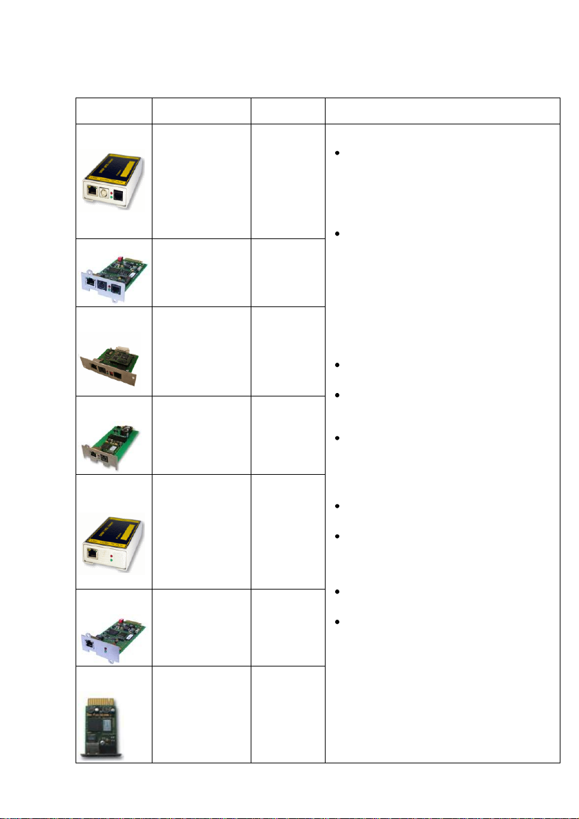
CS121
MODELS
FEATURES and
OPTIONS
Supported
UPS models
CS121 COMMON FEATURES FOR ALL
MODELS *
CS121L
external
Second mini din 9
COM port for
RS232. AUX port
for digital input/
output. MODBUS
RS485 option.
Remote RAS
management
options.
All 1400 UPS
models from
over 80
different UPS
manufacturers.
All these CS121
devices are capable of managing the
UPS models for which they are
compatible via the UPS’s native serial
protocol. Each CS121 integrates
seamlessly into all contemporary SNMP
facility management systems.
models have their own web server with
configurable event management for
automating responses to power and
UPS status conditions. This includes
Emails transmission, RCCMD net work
messages and shutdowns, logfile
entries, grafical logfile for statistics, UPS
shutdown functions and wake-up calls
for computers which have been
shutdowned before (wake-on-lan).
may be configured individually for all
actions and events
have a built-in scheduler for regular
tasks like battery tests, battery
calibration and UPS shutdown/restore.
have a wide range of network
management features for alarming users
and managing other SNMP devices and
general overall Computer and Power
resource management via RCCMD.
> 4MB include MODBUS-over-IP and an
optional MODEM interface.
offer a COM2 for connecting
environmental sensors or for connecting
other products and software to manage
the UPS.
have 2 years warranty and a free update
period of 3 years.
are made in Germany.
CS121SC slot
Like CS121 L
external, with
CS121 WDP (see
Appendix D.)
All Chinese/
Taiwanese
standard slot
UPS models.
CS121F
FUJI slot
Second mini din 9
COM port for
RS232. AUX port
for digital input/
output. Remote
RAS management
options.
FUJI UPS
CS121R
Riello slot
Like CS121 F.
Riello and
Aros UPS
CS121BL
BUDGET
external
Economic CS121
with LAN UPS
management only.
(No AUX port for
dry contacts, no
COM2 interface for
modem or
environmental
sensors.
All 1400 UPS
models from
over 50
different
manufacturer.
CS121BSC
BUDGET slot
Like CS121
BUDGET external,
with CS121 WDP
(see Appendix D.)
All Chinese/
Taiwanese
standard slot
UPS models.
CS121
MiniSlot
Like CS121 BSC
plus COM2
Multipurpose Port
Minislots from
Soltec,
Voltronic and
others
Properties of the CS121 device types:
7
Page 10

Product
Scope of Delivery
External
power
supply1
User
manual on
CD
Configuratio
n cable 2
Mini-8 COM
port
(MODBUS
via RS232)
Mini-8 COM
port
(MODBUS
via RS485)
CS121L
(External)
x x x
CS121SC
(Slot Chinese)
x x
CS121SCM
(Slot Chinese)
x x x
CS121F
(Slot FUJI)
x x
CS121R
(Slot
RIELLO/AROS)
x x
CS121LM
(Extern)
x x x x
CS121BL
(Budget Extern) 3
x x
CS121BSC
(Budget Slot
Chinese) 3
x
1.3 Scope of Delivery
The standard CS121-adapter package contains an SNMP-adapter unit with supporting
hardware and software (note, that the Budget-models do not have all features.)
Optional is a mounting kit for wall and DIN Rail mounting available.
1
For USA/CA UL: Supplied by NEC Class 2 Power supply only
2
For the configuration via serial interface with terminal software and for the connection to additional devices,
e. g. sensors
3
Configuration with network cable only
1.4 Functional Overview of the CS121
The CS121 is working with an integrated Simple Network Management Protocol (SNMP)
software agent. This agent exchanges data with the UPS via “get” and “set” commands and
forwards Trap Messages to desired receivers. This Trap Messages inform the user about
critical situations of the UPS, e. g. a power failure. In addition the CS121 can trigger RCCMD
(Remote Console Command) signals, messages, and shutdowns.
RCCMD is an additional single licensed software.
Otherwise the control of the UPS is possible, e. g. switching on bypass.
8
Page 11
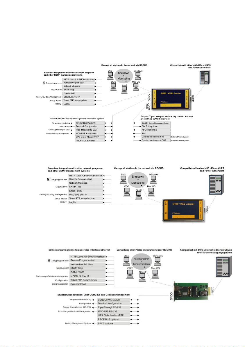
Functional Overview of the CS121 Professional
Functional Overview of the CS121 Budget
Functional Overview of the CS121 MINI
9
Page 12
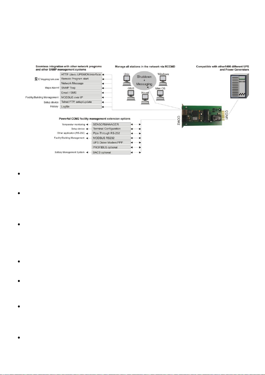
Functional Overview of the CS121_R_II
1.4.1 Functionalities of your CS121
SNMP Adapter CS121/CS121 Slot: The SNMP adapter is a compact unit requiring minimal
workspace (ca. 28x69x126 mm for the external adapter CS121L). The slot card versions of the
adapter get inserted into the extension slots of UPS models supporting such a card type.
Serial Port: Two DIP-switches change the adapter's serial port (COM2) to a configuration
port for installation or to a communication port for environmental sensors, modem or other
functions. The MODBUS-version uses the COM2 as RS485 interface and is not available for
configuration. The MODBUS version can be configured via web-browser only, Telnet and
default IP address.
SNMP-Traps for remote monitoring and pre-alarming: The main function of the SNMPadapter is the transmission of alarm conditions of the UPS to the monitoring station (SNMP
traps and RCCMD traps/commands). It also makes UPS data for users in the network upon
request available. With this function, it is possible to retrieve and monitor e. g. battery capacity
of an UPS from a SNMP management station. The event settings configuration menu also
allows for SNMP trap testing.
Remote Control: With this function it is possible to switch the UPS to Bypass (depending on
the model) or start battery tests. This remote command is executed either via the Network
Management Station or the UPS Management Software or any web-browser.
Telnet: Every Adapter can be reconfigured via the network, using Telnet or HTTP after the
initial configuration of an IP address for the adapter. Current UPS data can also be shown
using Telnet. Generally we recommend to use the web-interface, since Telnet (and terminal
configuration) allows to setup a basic configuration of the CS121 only.
Works with all major NMS: The CS121 works with most, widely used Network
Management Systems, e. g. HP Open View HP UNIX and Microsoft Windows NT, Novell NMS,
Spectrum, Sun NetManager, IBM Net View/600 and others. All SNMP systems, which either
allow the compilation of the MIB or already incorporate MIB RFC 1628 for UPS Systems, can
be used with the CS121.
Multiserver shutdown via RCCMD/RCCMD2 compatibility: The CS121 is able to initiate a
network shutdown with any RCCMD modules from the UPS-Management Software CD. A
TCP/IP based RCCMD signal will be send to all RCCMD clients in the network. This enables
10
Page 13
the remote shutdown of practically an unlimited number of client computers, independent of
the operating systems of the clients. RCCMD is an optional part of the UPS-Management
Software. Your UPS dealer is able to provide you with license keys for the RCCMD Software.
The UPSMAN service of the UPS-Management Software Suite is an optional module and not
required for that basic CS121 operations. We recommend to use the UPSMAN service only, if
the UPS is connected via serial or USB cable, if a CS121 is connected, you just need a webbrowser for the monitoring.
RS232 UPS Protocol Router – Pipe- through: The CS121 (not BUDGET versions) is able
to transfer the UPS RS232 protocol on COM1 directly to COM2. This allows the use of
additional monitoring software on COM2, while making extra hardware (RS232 Multiplexer) to
multiply the UPS comport unnecessary.
Log File: The CS121 got an internal log file synchronized with either a timeserver in your
network or from Internet timeservers. This log file can be accessed by web-browser,
UPSMON, JAVAMON or via FTP. The size of the log file is 250 lines, older entries will be
overwritten automatically.
Network Settings: The CS121 models are adjustable to the network environment. An autosensing function, 10Mbit or 100Mbit can be selected.
Email Client: The CS121 adapters incorporate a built-in SMTP email client, which is able to
send emails automatically, if an error occurs.
Web-Server: The CS121 models possess a web-server, which displays all functions and
settings of the adapter. Non-Windows users may use the UPSView as graphically display for
UPS data.
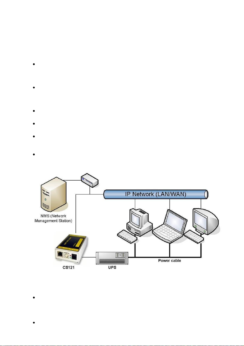
Network Connection: The below figure displays a CS121 into a network environment. The
CS121 is communicating with the UPS and displays all available data.
Figure 1: CS121 into a Network Environment
1.5 The Communication with the CS121-Adapter
MODBUS
Modbus is the de facto standard protocol in industry, which is used in the facility management.
All CS121 types include an MODBUS over IP interface and MODBUS over RS232. The CS121
MODBUS device types possess a RS485 interface at COM2.
SNMP
11
Page 14
The SNMP (Simple Network Management Protocol) is the Internet standard protocol for
managing devices on IP networks and is defined and standardized in Requests for Comments
(RFCs) specifications. Generally UPS systems are using the Management Information Base
(MIB) with the RFC1628 specification, which defines UPS specific devices.
The CS121 also comes with the standard MIB RFC1628. Because of this MIB is already part
of most SNMP software products, it is not required to compile the MIB (please search the MIB2
directory tree for a “UPS-MIB”). If you want to include your CS121 to a SNMP-Management
station, which does not have the standard MIB RFC1628, you can download the specific MIB
from our website http://www.generex.de/e/download/cs12x/download_p.html. Copy the MIB file
to the appropriate MIB-directory of your SNMP-station and compile this file. In most cases your
SNMP already has implemented this MIB and a compilation is only necessary, if you want to
read extra information than just UPS (e.g. for SENSORMANAGER, etc.).
UPSTCP
The most common way to communicate with the CS121 is over TCP. The CS121 contains
UPSTCP, which gives you a complete interface to integrate the adapter into your network. All
others use TCP for the access via web-interface (UPSView, UNMS II) or SNMP or MODBUS.
1.6 CS121 Overview of the Connections and LEDs
For CS121 L, LM, SC, SCM and other slot cards:
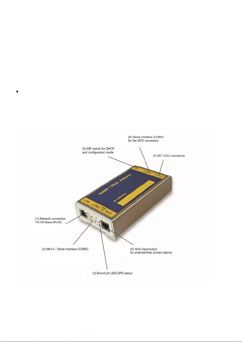
Figure 2: Connections of the CS121
1) LED state of the network connection: The LEDs of the RJ45 socket flashing
green, if a network connection is established and yellow, if network communication
12
Page 15
Green LED
Red LED
Adapter
OFF
ON
Adapter is looking for UPS/initializing. The start phase can
last up to 3 minutes
Flashing
OFF
Data flow/normal mode of the UPS
ON
ON
Communication to UPS interrupted
Operating Condition CS121 HW 131
LED-Signaling
Start procedure 1, unpacking of the OS
red flashing, green off, if an error
occurs, the red will glow steady
Start procedure 2, reboot of the OS
red long on
If the red and green LED shine at your CS121
HW131 during the reboot, huge broadcast traffic into
your network is present „recieve buffer overflow“.
The green LED is signalizing at the reboot, that the
„traffic buffer“ is full. Advice: You should filter
broadcasts via your switch, because it comes to
performance losing of the CS121 HW131
unnecessary.
red AND green during reboot
Normal condition
green flashing, displays the poll
interval to the UPS
UPS communication lost
Red will glow steady
Switch 1
Switch 2
Description
ON
OFF
Normal operation, device runs on the configured IP-address
OFF
OFF
Configuration mode with default IP address
10.10.10.10 and active COM 2 configuration for Terminal
software
is at present. The yellow LED displays the network traffic. If the yellow LED is
glowing steady, the network traffic is too high.
2) COM2 port as Mini 8 connector for the configuration or connection of external
devices.
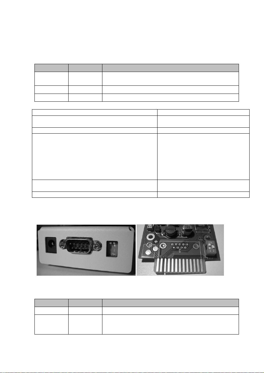
3) LED state of the CS121 HW131: The following tables are valid for the CS121
HW131!
4) AUX, in- or output for potential-free contacts, relays
5) DIP Switches: The DIP Switches differ 2 functions; the configuration mode and the
normal operation with optional DHCP.
Figure 3: CS121L (left) in configuration mode (IP 10.10.10.10) and CS121SC (right)
in normal mode
13
Page 16

Note: Into configuration mode the full functionality of the CS121 is not
available! Please change to a valid network address and put DIP-switch
1 to position ON as soon as you made your basic network settings! After
this, please continue configuring your CS121 in your network. Please
follow up the procedure in chapter Error! Reference source not found.
Error! Reference source not found. in this manual.
Please note, that the CS121 Budget versions got no COM2 port!
6) Serial interface (COM1): For the connection to the UPS
Note: UPS interface cable (external devices only): Please use the manufacturer’s
serial port cable that came with your UPS to connect the UPS with the SNMPadapter. Please contact your UPS manufacturer, if you have questions. Only use
the original RS232 UPS cable for communication, which was provided with the
UPS. If your UPS has a contact closure port, please use the manufacturer’s special
cable. Please consult your UPS dealer for further information regarding special
cables.
7) Power supply, the external CS121 got an external power supply (9 – 12VDC)
Note: If you are using a different power supply unit from the one in the adapter
package, please consider that the polarity is set correctly. The adapter
might be damaged if the wrong polarity is used. The power supply
voltage should be at least 9V, 12 V is recommended.
For the CS121SC models C and the slot card, there are no power supply
units. These units will receive power directly from the UPS device. The
SNMP adapter C and slot card both incorporate a variable 9-36V input.
2. Quickstart
This quickstart describes the basic functions and settings of the CS121. The CS121 can be
configured via Telnet, Terminal and HTTP. The Telnet configuration uses the same network
interface as the HTTP configuration. The Terminal configuration requires a serial connection to
a workstation.
We recommend the configuration via HTTP, because it is the most comfortable one and that is
why we describe the HTTP configuration in this user manual.
After you finished the CS121 hardware setup, all 3 configuration modes are at present. If you
want to use the Telnet or HTTP configuration, it is required to add a temporary network route
to the CS121 configuration mode IP address 10.10.10.10.
Please use the following access data:
User: admin
Password: cs121-snmp
3. Initial Operation of the CS121
3.1 Connect your CS121 ...
In generally you can select between 3 ways to configure the CS121:
You can execute the HTTP configuration via web-browser.
You can execute the Terminal configuration via web-browser.
14
Page 17

You can execute a Terminal configuration via the serial interface (CS121 device types with a
COM2 port only) with the CS121 configuration cable (optional, not included). This
configuration-mode allows you to make the basic settings for the network connectivity and for
the configuration of the event and alarm settings.
3.1.1 ... via LAN
Connect the CS121 with RJ45 cable (not included) to your LAN.
3.1.2 ... via serial port
The CS121 contains two serial ports (not BL and BSC-versions), COM1 provides the connection to the
UPS and COM2 is used for the configuration of the SNMP adapter.
Configuration cable (not included):
With the configuration cable you could connect the serial port (COM2) of the CS121 and the serial port
of a workstation with terminal software. It is sufficient to use a Dumb-Terminal or Terminal emulation
program, such as e. g. Microsoft-HyperTerminal. Please ensure during the configuration of the CS121,
that the DIP switches are into position OFF.
CS121 MINI/CS121 R_II:
It is required, that the DIP Switch 2 remains in position OFF, otherwise the device will not start (valid
for CS121Minislot/CS121R_II built 2008- 2010 from serial number 0123M-0001 to 0123M-1135).
3.2 Verifying the CS121 Connectivity
After the CS121 is connected to the UPS and to the workstation via serial port or via LAN, please verify
the connectivity before you start to configure the CS121. The setup system can be checked before and
after a configuration using the following 3 steps:
UPS Status Displays (LEDs)
During the boot procedure, the red LED is on, whereas the green LED is off, please take a look into
chapter 1.6 for the complete signaling.
After five to ten seconds after the boot-process, the green LED flashes rapidly; this indicates that the
SNMP-adapter is trying to start the communication. The adapter will indicate its communication
accessibility with random green LED flashes.
Network status LEDs
The LEDs, integrated into the LAN-Connector (RJ45-), will signal a connection to the network with
green and with yellow network connectivity.
CS121 Ping Echo
Perform a PING command from the SNMP station or from another workstation in your network.
If you do not get a response, check the CS121 network connection and IP address. The IP address of
the adapter is set to 10.10.10.10, if DIP Switch 1 is in position OFF (configuration mode).
Note: The different response rates during the ping process do not correspond
to an error. The CS121 does not answer every ping signal at the same
time, due to different sized UPS protocols. If UPS protocols are of
extensive size a temporary timeout can occur. A permanent timeout
however is an error.
15
Page 18
3.3 Setup of the Basic Network Configuration
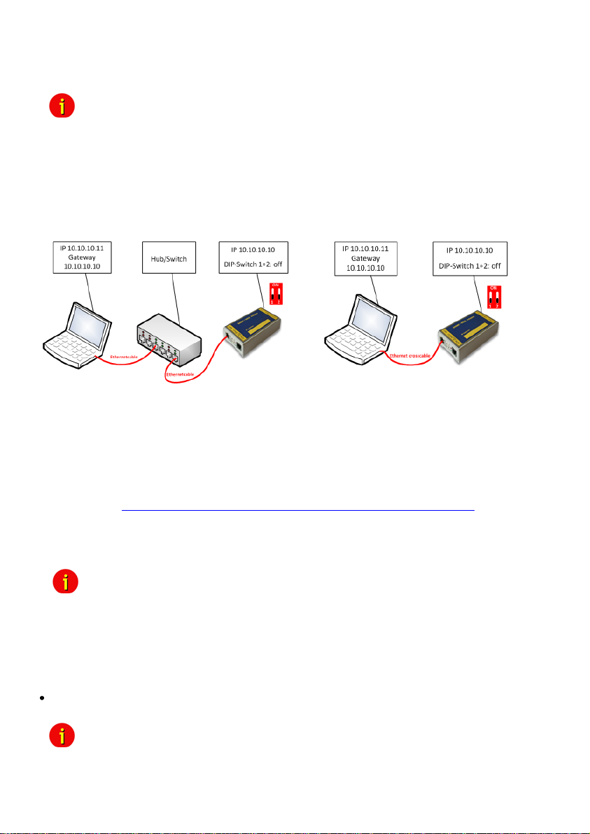
cross cable (Ethernet cable for the connection directly). Set the IP address of the workstation
Note: We recommend the following settings for the operation of the CS121 via
with a cross cable to an IP address of the same network segment, e.g. 10.10.10.11 AND set
the gateway to 10.10.10.10.
A network cross cable is a PC-PC network cable, which does not require a switch or a hub
between 2 network workstations (2). Most modern workstation network cards have an auto
detection, so any network cable may be used. Only if you do not have such a cable, connect a
switch or Hub between your workstation and the CS121 (1).
Figure 4: Connection PC-Switch/Hub and CS121 (2) Connection PC-Cross
Cable/Network Cable and CS121
3.3.1 DHCP – Obtain an IP address automatically
By default DHCP is off at all CS121. From CS121 FirmWare Version 4.25.x you can switch on
DHCP via DIP switch 2 manually. Therefore the CS121 will get a DHCP IP address from the
DHCP server during reboot. Prior of that, you should detect the MAC address of the CS121 to
be able to find the IP address on your DHCP server. You can also use the GENEREX
Netfinder tool (http://www.generex.de/generex/download/software/install/NetFinder.zip). This
tool searches all CS121/BACS devices into your network environment. We recommend to use
static IP addresses, because the CS121 is used for multi server shutdowns via RCCMD too
and it might be, that the DHCP server got a breakdown. For that reason the delivery default of
the CS121 is always with DHCP OFF!
Note: The function DHCP ON/OFF is valid for the following models only: all
3.3.2 Establishment of a static CS121 IP address manually (default delivery state)
The minimum requirement to operate the SNMP-adapter is to set the IP address, subnet mask
and the UPS model:
The DIP-switches of the SNMP-adapter firstly need to be set for the configuration. DIPswitch 1 is switched OFF in the top position as well as DIP switch 2 is switched OFF.
Note: For slot versions you have to insert and remove the device for any
16
CS121 HW 131 and all BACS II Webmanager Budget (not valid for all
CS121 HW 121, SiteManager, SiteMonitor, MiniSlot, CS121_RII and
Piller I/O Board)!
reboot-process. This will not have any effect on your UPS but we
recommend doing such operations only when the UPS is not supplying
any load!
Page 19
As soon as the network-LED is flashing, add a TCP/IP route on your computer for IP-
address 10.10.10.10. This is done via a call from your command line e.g. "route add
10.10.10.10 <your computers IP address>“. See also route -? for more help of route syntax.
Test if you can ping the device now: Enter command „ping 10.10.10.10“ and check if there is
any response. Now you can connect with any Telnet or HTTP-software and continue with the
configuration.
3.3.3 Using HTTP/Webbrowser
finished your whole confguration, please note, that it is reqzuired to execute the “Save, Exit &
Reboot” function via CS121 menu “Save Configuration”.
The entire configuration can be done via Webbrowser. Please use the default IP-address
10.10.10.10 and the TELNET password (default: “cs121-snmp”). The username is always
“admin”.
Please do never close the web-browser or telnet window during saving process! If you close
the configuration window too early, you might destroy the configuration file “upsman.cfg”.
Please note, that the reboot process could last up to 3 minutes.
For the configuration using the webbrowser please observe the following:
We recommend the use of Microsoft Internet Explorer 6.x (or higher) or Mozilla 1.3x. Please
note, that Java scripting has to be activated. Using Internet Explorer, the corresponding
settings have to be made under “Internet options” - “security”.
We also recommend never to use the history function of the browser, as this may lead to
multiple transfer of commands (e.g. delete event jobs) to the adapter.
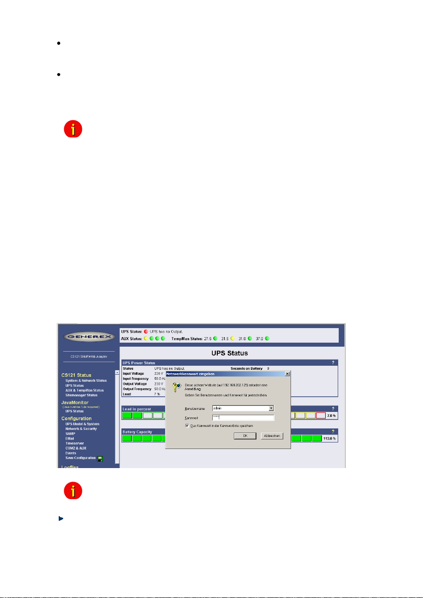
Upon entering a HTTP-configuration session, the user is required to enter a username,
”admin”, in addition to the password ”cs121-snmp”.
Attention! Please finish all configuration menus via “Apply”button. After you
Figure 5: HTTP - Administrator login
Note: If the HTTP-method does not seem to be available, check to see
whether or not the red LED UPS Status glows.
Call Configuration, “UPS Model & System” and choose your UPS Model from the drop
down list. Further configurations like Power, baud rate, cable type etc. were made
automatically (ensure your Browser has enabled JavaScript) and do not need to be set. We
strongly recommend to keep the default settings for this UPS unless you have instructions
from the UPS maker.
17
Page 20
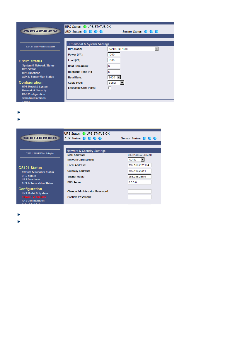
Figure 6: HTTP - UPS Model & System Settings
Apply your settings with the button at the right side.
Change to menu “Network & Security” and specify IP-address, Gateway and Subnet Mask
to the CS121-adapter.
Figure 7: HTTP - Network & Security Settings
Apply your settings with the button at the right side.
Change to menu “Save Configuration” and click “Save Configuration”.
3.3.4 Configuration using Telnet / MS-HyperTerminal
Use of Telnet, enter the command: „telnet <IP-Address>“, whereas <IP-Address> is in the
configuration mode set to 10.10.10.10. Please note, that since CS121 firmware version 4.x, the
basic settings (IP address, network settings) are at present only.
18
Page 21
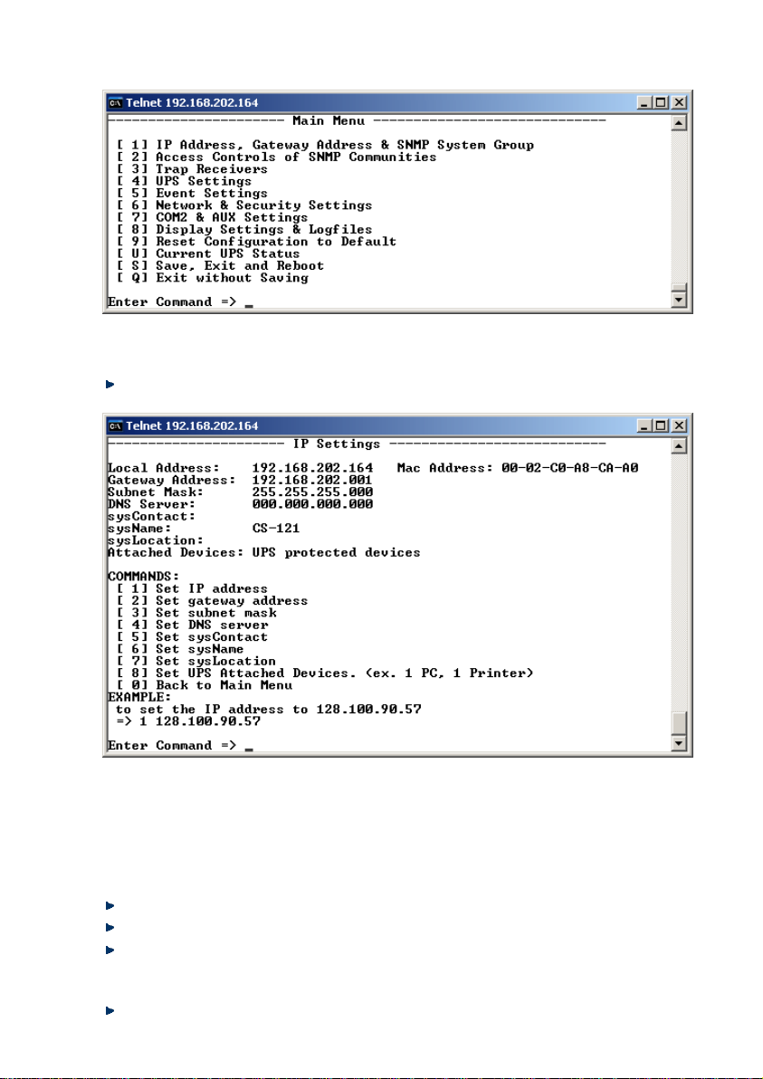
3.3.4.1 Main Menu & IP-Settings
Figure 8: Telnet - Main Menu
To select any option in the main menu enter the number of the option at the Enter command
=> prompt. The program displays the desired screen.
Type 1 at the prompt and you enter the menu “IP Settings”. Within this menu you can
enter basic network configurations, e. g. IP address, Gateway-address etc.
Figure 9: Telnet - IP Settings
To change values, enter the number of the option, type <space> and enter the name. Press
<enter>. Your new value displays next to the field heading on the top of the screen. If you want
to return to the main menu, press 0 (zero) and <enter>.
For example: To assign the IP-address of the SNMP-adapter, the gateway and the subnet
mask type at the prompt:
1, <space>, the IP address of the SNMP adapter, <enter>
Enter Command => 1 192.10.200.0
Enter Command => 2 192.10.200.254
Enter Command => 3 255.255.255.0
To assign the system contact name, type 5 and enter the name of the person to contact about
the SNMP adapter.
Enter Command => 5 Mr. Harry Hirsch
19
Page 22
To assign the UPS name SysName, type 5 and enter name of the UPS:
Enter Command => 6 USV 1
To assign the UPS location SysLocation, type 6 and enter the location name:
Enter Command => 7 Building 12
3.3.4.2 UPS Settings
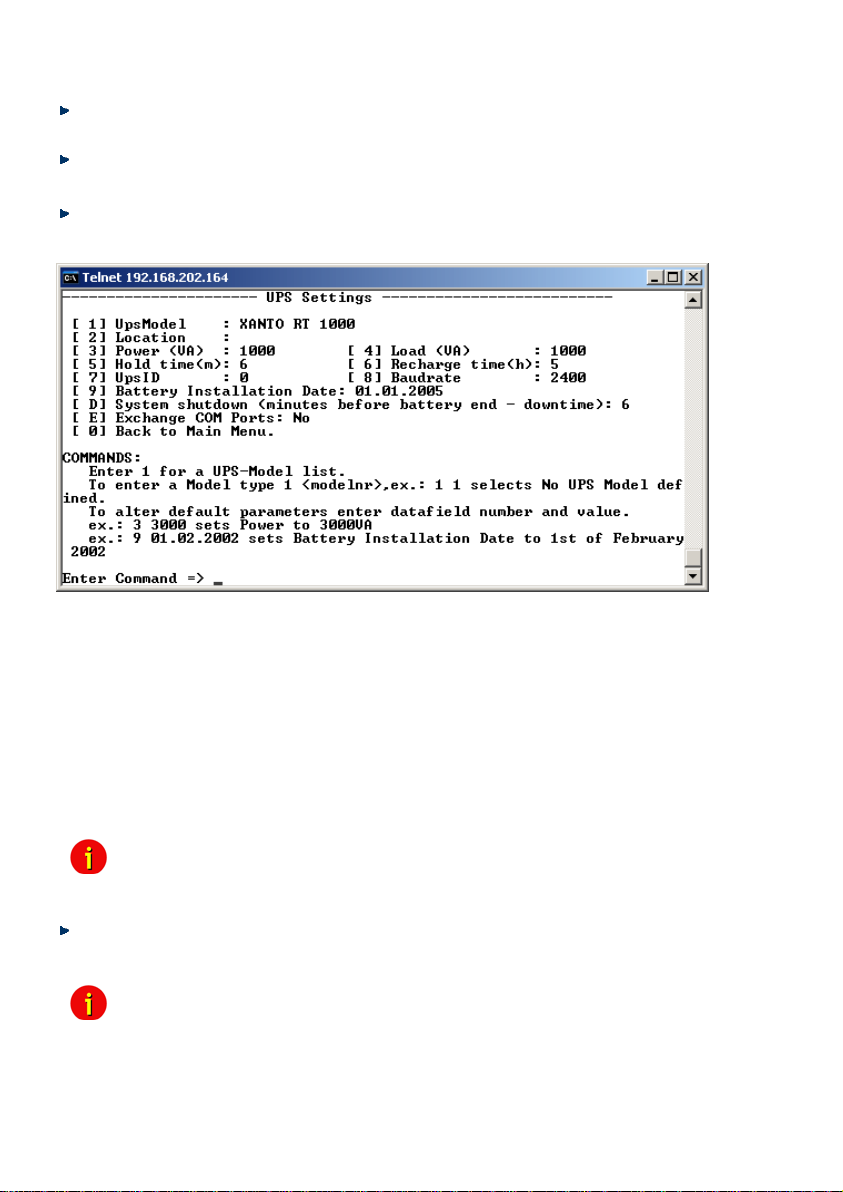
Choose option 4 from the main menu and you enter the menu “UPS Settings”. Within this
menu the user needs to select the UPS model the CS121-adapter is connected to (usually at
COM1).
Figure 10: Telnet - UPS Settings
The CS121-adapter distinguishes here generally between Cable- and Serial-models. With
Cable, the adapter and the contact interface of the UPS are connected with a special cable.
Using Serial, UPS models connect to the adapter via the serial UPS-cable. (Part of the UPS
package). Serial is default, when the user selects a UPS model name from the drop-down list.
When Cable is used, please search the list for the corresponding UPS model and cable type.
The CS-121 supports serial models with its own RS-232 protocol as well as contact UPS
models with the cable types O,C,1-10. Those contact cables are UPS or alarm system specific
and should be provided by the corresponding manufacturer. Our Cable documentation shows
examples of those cables if they are individually made cables.
Please choose the corresponding serial UPS model or cable model communication
parameters. Parameters like baud rate etc. are present for the corresponding UPS model.
Note: By selecting the UPS model, the communication protocol is selected at
the same time. If your UPS does not appear in the list, ask your UPS
dealer if another model from the same series can be substituted.
Select Option 1 to get a variety of possible UPS models. After chosen a model, the default
values of the corresponding UPS model can be configured by typing the number of the option
followed by the value.
Note: Please do not change parameters except of UPS-model unless you want
to choose specified configuration according your UPS-model!
Please note option “D”: “System shutdown (minutes before battery end – downtime)“: This
value determines how many minutes before a complete battery unload the event “System
shutdown” from event menu is executed.
20
Page 23
The shutdown time interval needs to be set large enough, so that adequate time for a system
shutdown is allocated before the UPS runs out of power. Please calculate this value
generously e.g. if the battery time of the UPS is 10 minutes and the event procedure takes 2,5
minutes, ensure you start (configure) the shutdown (or other event action) 3 minutes before the
UPS is switched off, so that more than enough time is available to complete the corresponding
event action.
3.3.4.3 Saving Configuration
Call “Save, Exit and Reboot”-command from the main menu. (The communication to the
adapter will be lost).
ATTENTION: Keep the Telnet, Terminal, web-browser window open until the device has been
lost or you see a message that reboot is under progress. If you close the configuration window
too early it may corrupt the upsman.cfg configuration file.
Note: Various options and settings for UPS-configuration can be done under
3.4 CS121 Restart and Boot Procedure
After you have finished the basic IP- and network-settings you should set DIP-switch 1 in
position ON and restart the adapter with your configurations.
You can perform a CS121 restart by unplugging the power supply of the CS121 and wait, until
the CS121 has restarted with your configurations.
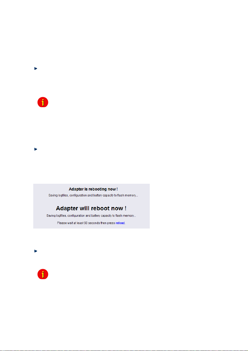
Alternatively you can restart the CS121 with the “Reboot”-Option in the “Save Configuration”-
menu of the web-browser. The following message will displayed:
Figure 11: HTTP – Adapter reboot dialog
A successful restart of the adapter is indicated with the CS121 UPS- and network-LEDs as
described in section 3.1 Connect your CS121 ....
Reconnect your web-browser with the adapter using the configured IP-address. (e.g.
http://192.168.10.123)
Your CS121 is now ready for further configurations!
Telnet or HyperTerminal, e.g. setting access controls of the SNMPcommunities, set traps, set display settings, etc. However, the
configuration via web-browser offers a much more convenient way to
configure the CS121. If you have any possibility we recommend you to
use this way.
Note: If the adapter’s HTTP-service is not available, check to see whether or
Further, test if you reach the adapter with a ping-command. Enter
not a red Status-LED is lit.
command „ping <IP-address>“. If the adapter doesn’t answer to the ping,
check also whether your network routes the IP-address.
21
Page 24
4. Configuration of the CS121
Note: After you have finished the basic network configuration you should have
set DIP-switch 1 in position ON and rebooted the adapter. At the SC slot
cards you have to remove the card from its slot and change the DIP
Switch 1 to position ON. After this, re-insert the card. Info: There is no
risk to remove/insert the slot card, there will be no effect on the UPS
output.
4.1 CS121 Menu System & Network Status
The Menu “System & Network Status” shows basic information about general configuration
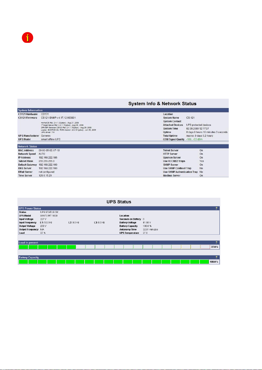
settings.
Figure 12: HTTP – System & Network Status
The menu “UPS Status” gives information about the actual UPS-data, above all the state of
charge and battery load:
Figure 13: HTTP – UPS Status
The menu “UPS functions” allows you to perform USV test- and control-scenarios like battery
tests, etc. The UPS functions depend on the UPS type and its functions. Some UPS only allow
a remote on/off, others have more functions.
22
Page 25
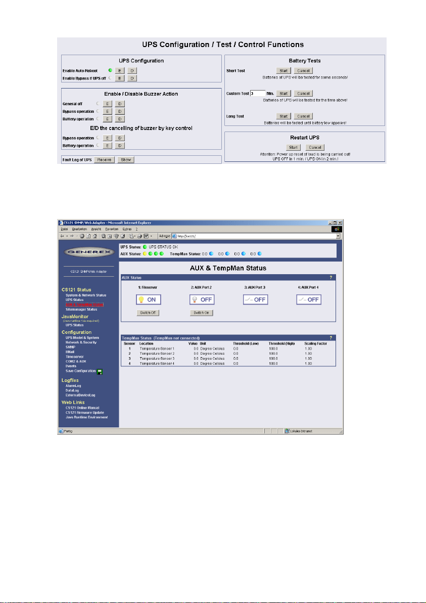
Figure 14: HTTP - UPS Functions for AEG UPS
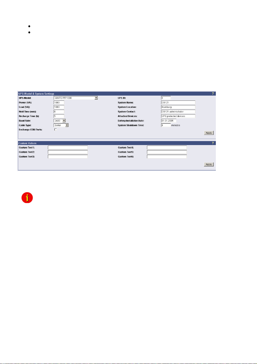
The AUX & SensorMan status shows the actual measurements of the connected
environmental sensor devices SM_T_COM, SM_T_H_COM, SENSORMANAGER, CON_AUX
or CON_R_AUX.
Figure 15: HTTP - AUX & SensorMan Status
In the above figure, a button menu is presented in which the ports 1 and 2 can be clicked on
and off. A yellow light bulb indicates that output to the corresponding port is being provided,
while the gray unlit light bulb indicates the status of being switched off in which case the
connected device is not being provided with power. The buttons „Switch Off“ and “Switch On”
are password protected. This is the same password that has been set in the CS121configuration. The ports 3 & 4 are configured as input sensors, here the OFF symbol shows an
open contact, and alarm would show a closed contact. The AUX port of CS121 can be
configured as output or input – or a mixture of both.
4.2 CS121 Menu “Configuration”
4.2.1 Saving Data
ATTENTION! The following is essential for all entries of configuration data:
23
Page 26
Close all web-browser menus via the “Apply” button.
If you have finished your configuration completely, get into the CS121 menu Save
Configuration and execute the “Save, Exit & Reboot” function.
IMPORTANT! Do not close the Telnet or web-browser window, until the connection to the host
is lost or you got a message, that the CS121 is rebooting. If you close this window to early, it
might be, that you will damage the configuration file “upsman.cfg”.
Please note, that the reboot process of the CS121 could last at least 3 minutes.
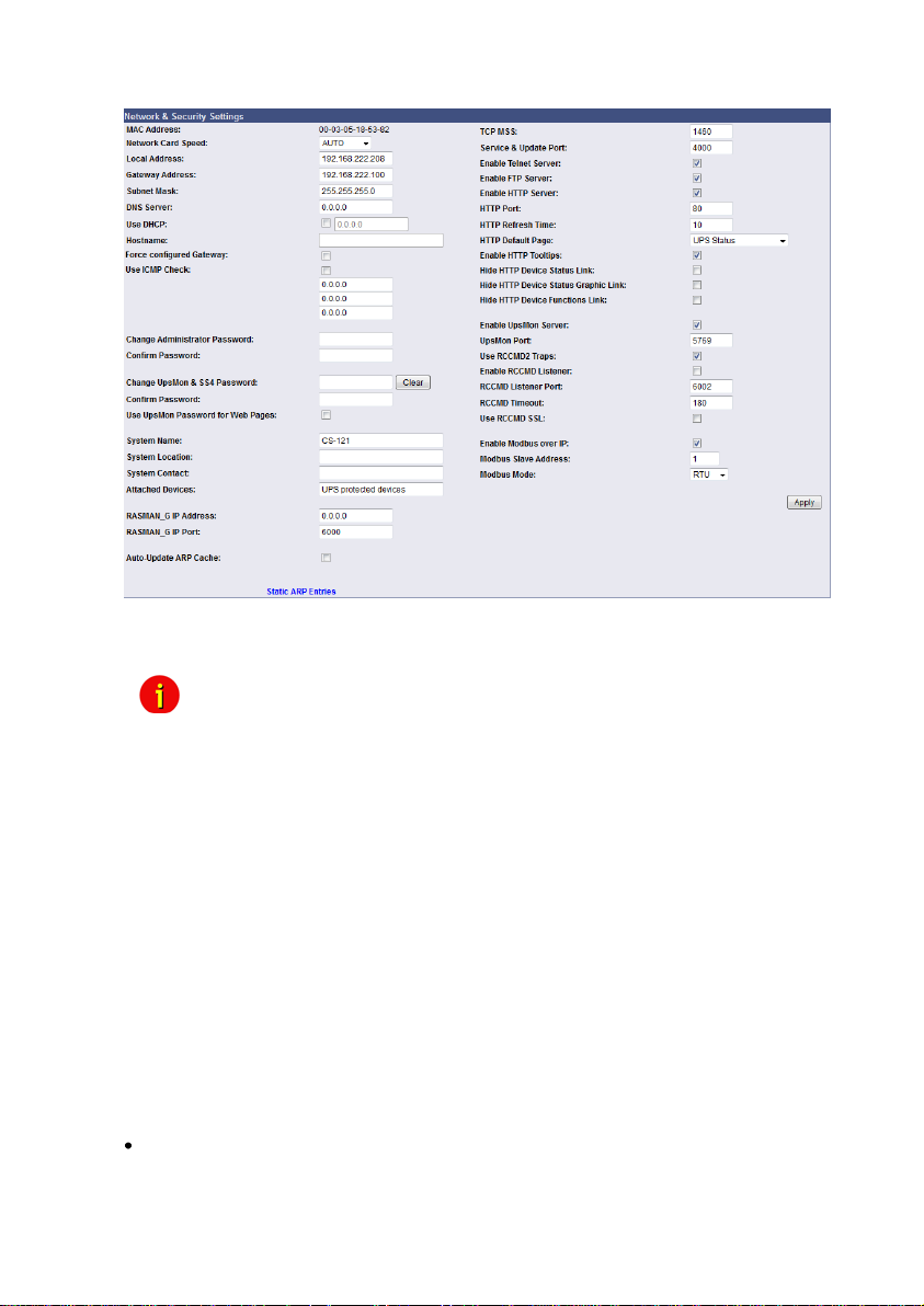
4.2.2 UPS Model & System
Use this menu to define the communication between the CS121 and your UPS.
Figure 16: HTTP - UPS Model & System
With the parameters UPS ID, system name, system location, system contact you can describe
the UPS and CS121.
Note: Do not change the default UPS-Parameters for Baud Rate and Hold time
unless you have special instructions from the UPS maker.
Please note the field “System Shutdown Time“: This value determines, how many minutes
before a complete battery unload the event “System shutdown” from the event menu will be
executed. Attention: This EVENT is the final task a CS121 can initiate, before the UPS
switches off! DO NOT use this event for triggering shutdowns via RCCMD etc., because the
remaining time in this status is not secure. We strongly recommend to use the event Powerfail
and configure the RCCMD shutdown signals with a UPS “remaining time”, this is the best way
to send RCCMD shutdowns to several IP addresses in a certain logic or sequence!
The section „Custom Values“ contains 6 fields with can be used to save custom specific
comments concerning your UPS.
24
Page 27
4.2.3 Network & Security
Figure 17: HTTP - Network & Security Settings
This menu configures the CS121 network card settings, passwords and enable/disables
several adapter and network services.
Note: We recommend to set the Network Card Speed NOT to “Auto”, but
rather to the accordant speed of your switch. In addition we
recommend to open the TCP/IP and UDP ports only, that the CS121
is using. Please take a look into the chapter Appendix D. To
stabilize the CS121 in larger networks we recommend to close the
update TCP Port 4000 at the CS121 configuration or at your switch.
Please note, that you are not able to update the CS121 firmware
anymore if port 4000 is disabled. Enable the port 4000 again, if you
want to update the firmware.
The CS121 firmware version 4.30.x provides the definition of the TCP MSS value. The
Maximum Segment Size defines the amount of bytes, which will be send as reference data into
a TCP segment. The default is 1460. If you got problems with a VPN connection, change the
TCP MSS value to 1100. The TCP MSS value is valid for HTTP only!
Enable RCCMD Listener: Among others, here you can allow the CS121 to act as an RCCMD
listener client. This makes it possible for another UPSMAN-Manager, CS121, SITEMANAGER
or other RCCMD compatible sender to send the adapter an RCCMD command like sending
one of the AUX output ports a high or low signal or to start other actions.
You can also set the MODBUS configurations in this menu. The configuration requires only the
following entries:
Enable Modbus over IP: Every CS121 model can also transfer UPS data via the MODBUSprotocol on IP (port 502). You may use any MODBUS client to read the UPS value from
CS121. For using the RS485 interface, you must use a CS121MODBUS (special hardware) in
other cases you have to use MODBUS-over IP. This is enabled by default, you may disable
this feature via Telnet or HTML-configuration.
25
Page 28
Modbus Slave Address: Enter the corresponding number, meaning which number in the
chain (bus) the adapter is (until ID 247).
Modbus Mode: RTU (binary mode) or ASCII mode text output. Please select the type with
the scroll down menu.
parameters 7/E/2, or 7/E/1 or with 7/N/2 from baudrate 1200 to 38400. We recommend for
ASCII the use of 7/N/2 and the highest baudrate supported by your device.
RTU Mode works at CS131 & CS121 platforms with communcation parameters 8/E/1 or
8/N/2 or 8/N/1 or 8/E/2 or 8/O/2 or with 8/O/1 from baudrate 1200 to 38400. We recommend
for RTU the use of 8/E/1 and the highest baudrate supported by your device.
manipulation. The default password is "cs121-snmp". In case you have "forgotten" your
password a master password can be generated using your adapter serial number. Please
contact your manufacturer for more information.
and allows to open UPS FUNCTIONS and SS4 FUNCTIONS only to specific users. With this
password, which is valid for the TCP/IP connection to the UPSMON too, the user may switch
on/off the UPS, start battery tests, switch SITESWITCH 4 outputs, but can not change any
other setting on the CS121 configuration. Exception: If the administrator password (default
identic) was not changed. The UPSMON is a Windows client, which is able to connect via
network to the CS121. The UPSMON and SS4 password is used as protection. Advice: For the
activation of the new password (apply button), it is required to reboot the CS121 via the „Save,
Exit & Reboot“ function.
The CS121 firmware version 4.52.x provides the entry of a Hostname, if you want to use
DHCP.
In addition the new feature “Force configured Gateway” is disabled by default. At disabled all
requests will be responded to the requesting IP address and its MAC address directly. If
enabled, all incoming requests will be routed through the defined Gateway exclusively.
4.2.4 The CS121 with DHCP utilization
The firmware version 4.xx and higher contains DHCP. With DHCP your CS121 will get an IP
address automatically from the DHCP server. Please note, that this address allocation should
be fixed, because RCCMD, which checks the addresses of the senders, will not be functional.
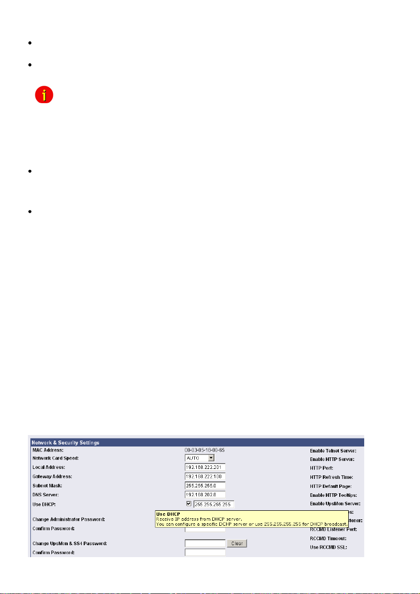
Click the “Network & Security” button in the CS121 configuration and check the “Use DHCP”
box.
Note: ASCII Mode works at CS131 & CS121 platforms with communcation
Change Administrator Password: The password protects against unauthorized usage and
Change UPSMON & SS4 Password: This is a separate password (default: “cs121-snmp)
26
Page 29
Click the “Apply” button and reboot the CS121 with the “Save, Exit & Reboot” function.
Fallback address: If the DHCP server will not be available, just reboot the CS121 to use the
fallback address. This address is equivalent to the settings of the local address in the menu
„Network & Security Settings“. When DHCP will be available again, just reboot the CS121 to
use the DHCP address.
4.2.5 The CS121 with ICMP Check
From the firmware version 4.26.x the CS121 is able to answer and send ICMP polls, to check
the quality of the network and, in need, can reboot itself.
Figure 18: HTTP - Network & Security DHCP Settings
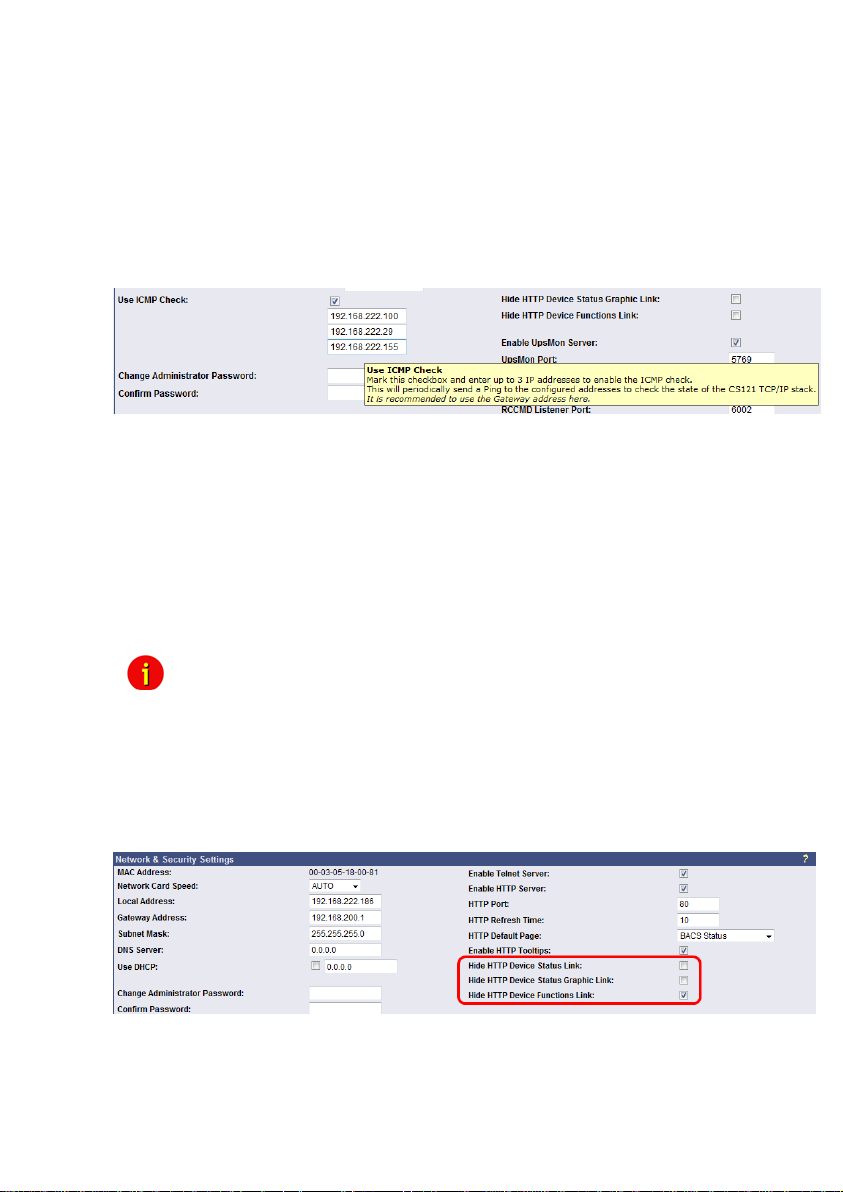
You can enter up to 3 addresses, which will be checked via ICMP. Before the ICMP Check
Figure 19: HTTP - Network & Security ICMP Check
works, at least one of the entered addresses must be available. Only after successful ping the
task is active. If all 3 addresses are not be reachable, the CS121 will reboot itself after 750
seconds (default). We recommend to use the IP address of a gateway and 2 more addresses,
which are reachable steady. If you enter only 1 or 2 addresses, the amount of the checkable
addresses is reduced and the possibility to initiate a reboot will increase unnecessarily,
because less addresses are at hand for the check of the network quality. If the CS121 will
reboot itself often at enabled ICMP check, an analysis of the network is required (e. g.
Wireshark), to be able to find the reason. If this should not be possible, you should disable all
ports at your switch, which are not required for the CS121, to avoid unnecessarily network
traffic. Please take a look into chapter Appendix D., D.9 for further information.
Note: The CS121 supports 3 functions of ICMP via RFC 792:
0 – Echo reply
3 – Destination unreachable
8 – Echorequest
4.2.6 Function hide of HTTP links
The CS121 firmware version 4.23 or higher provides the function to disable the following
HTTP links into the “Network & Security” menu:
Figure 20: HTTP – Network & Security Hide HTTP Links
4.2.7 Configuration Static ARP Entries
The CS121 firmware version 4.x or higher provides the configuration of static ARP entries into
the “Network & Security” menu:
27
Page 30
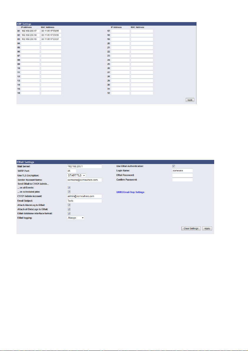
Figure 21: HTTP – Network & Security ARP Settings
You can determine into the ARP Settings, which IP address to which MAC address will be
assigned. Therefore the ARP entry will not expire for this IP address. The ARP table will be
determined firmly and will never expire! Case of application: HP Teaming or an ARP entry is
desired, but the ARP table cannot be restored automatically.
4.2.8 Email
If you wish to define actions to send Emails depending on specified events you need to
configure the Email settings.
Figure 22: HTTP - Email Settings
In this menu the internet name of your SMTP mail client is required. If DNS is not configured,
the actual mail server name’s IP address has to be entered. Please also note that the sender
account name (e.g. [email protected]) should not be a random name, since some mail
servers do not allow this. We recommend to use an existing account e. g. [email protected].
Most servers require matching account names and mail server names. E. g.
[email protected] would be correct, whereas just “someone” would not be sufficient.
If the server name and account name do not match, the following error message will be
displayed in the CS121 alarm logfile (after some minutes): “Mail: bad answer from mail server:
501 UPSIP204@wrong server.com sender domain must exist.”
The user can check the logfile if the email transfer works. The logfile (text.log under the CS121
root directory ../Flash/text.log) can be viewed using FTP, via the UPSMON tool or via the webbrowser “Alarm log”.
Select the accordant TLS encryption:
- None
28
Page 31

- STARTTLS = If the mail server is supporting STARTTLS flags, the email
communication will be encrypted
- SSL/TLS = The email communication will be encrypted
The firmware version 4.xx provides the function „Attach AlarmLog to Email“. Enable it and
every email, that will be send from the CS121, will contain the AlarmLog. If you enable the
function „Attach all DataLogsog files to email“, every email will contain the AlarmLog,
UPSData.log and ExternalDeviceLog. Additionally the email contains the parameters MACAddress, UPS Model, UPS Location, IP-Address of the CS121, System Time and Actual
Event.
The firmware version 4.30.x provides the function Email database interface format. This
option will send Emails configured into the Events/Alarms configuration in a standard, machine
readable format. This allows the monitoring and interpretation of alarms by the email software.
You can select the following options for the email logging:
Never
Always
Erors, only
Mailservers outside the LAN require a username and password. For this function please use
“email authentication” and enter a username and the corresponding email password (twice).
Note: Do not use email authorization if this is not required by your mailserver !
If authorization is required, the email function “AUTH LOGIN” (the CS121 adapter supports
only this function) needs to be supported (e. g. freemail.de). This changes the protocol from
SMTP to ESMTP and a password is required.
The length of the password should be a minimum 3 and a maximum of 63 characters.
Send a test-mail to validate your settings after you have applied the mail-settings. A short
message on the menu indicates whether the test-mail could be sent or not.
The usage of the settings in the live operation requires the reboot of the CS121 via the “Save,
Exit & Reboot” function!
Note: Please ensure that you have specified a DNS-server in menu “Network
& Security” if the mail-server could not be reached. You can transfer up
to 511 signs.
4.2.9 Email Trap
The Email Trap function provides the transfer of device/UPS data via POP protocol to the
UNMS II. Into the UNMS II AdminConsole can the connection type be defined, like the other
(UPSTCP, SNMP, RAS), but it is only into the UNMS II module extension „Data Center /
TeleService available
Unlike to the other connection types, this one can assimilate incoming email traffic only and is
therefore the optimal fitting for relevant to security customers and remote monitoring.
Transfer protocol: POP
Reference data: IDP, VDP, propritary data
Data format: JSON (as attachment)
Mail server configuration: globally for all connections, into the UNMS II
AdminConsole
Mail client configuration: per device as connection type, into the UNMS II
AdminConsole
One mailbox/user for all devices, IP- and MAC address distinct
29
Page 32
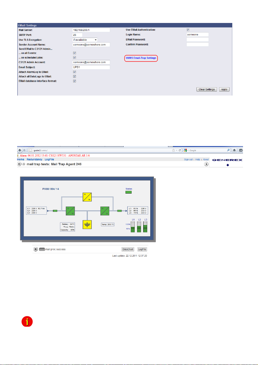
Figure 23: CS121 Email Settings
If Email-Trap is arranged and the UNMS II got the TeleService module extension, every device
can be monitored via emails. The UNMS II displays every device in an own grafical screen with
all measuring values and timestamp of the latest update. If a status will change, the values will
be updated immediately. If no status changes, the measuring values will be updated into the
defined period of time for the „Heartbeat“.
Figure 24: UNMS II screen with timestamp of the latest measuring values
update
4.2.10 Email Trap Configuration
The feature will be enabled through an entry into the Email Trap configuration. If you delete the
entries, the feature will be disabled.
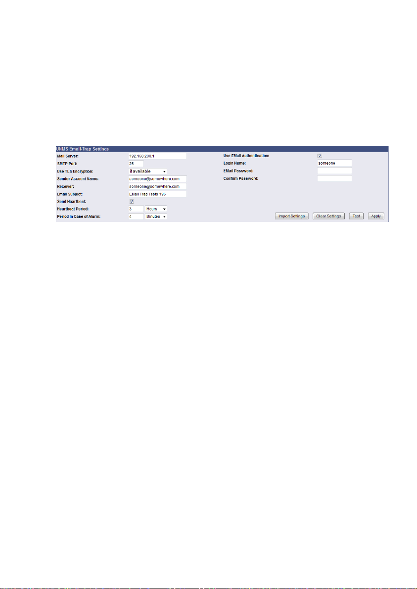
You can use the „Import Settings“ feature to import your email settings from the previous
page easily.
configuration from the previous page, but we recommend to create an own email account
for the UNMS II Email Traps, because this emails are non-readable for the user and the
email account will be stressed unnecessary. This Email Trap account should be used
30
Advice: The Email Trap configuration is in accordance with the common email text
Page 33
from the UNMS II with TeleService only. You should change the parameter after using the
import settings feature accordingly.
The „Heartbeat“ via email is an additional feature for the UNMS II with TeleService. A new
„Heartbeat Timeout“ is at present, in the case, the „Heartbeat Email“ was not received.
Thereby a disconnect of the CS121/BACS connection will be monitored. If the „Heartbeat
Email“ was not received for 12 hours, an alarm will be triggered.
You can define the interval for the „Heartbeat“ at the CS121 and we recommend to use an
interval of 12 hours. Since CS121 firmware version 5.16.x you can define an intervall for the
Heartbeat in case of an alarm.
Figure 25: UNMS Email Trap Settings
You can trigger an Email Trap via « Test » button. The CS121 AlarmLog will log the sending
and the UNMS II with TeleService should display new measuring values within 2 to 3 minutes.
The default selection of the Email Trap events shows, which events are critical and should be
sent. If you want to send further events, you can enable them here by clicking the « Apply »
button. Please note, that it is required to execute the « Save, Exit & Reboot » function, after
you have finished your configuration.
4.2.11 Timeserver
The CS121 uses a timeserver to supply the correct date and time of any event in its local
logfile. If no Timeserver is set, the CS121 will not use date and time in the logfile, but a date
stamp of 1970.
31
Page 34
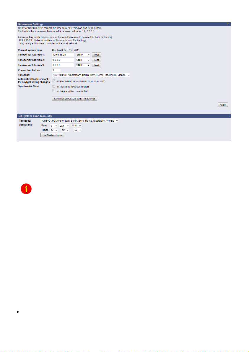
Figure 26: HTTP - Timeserver Settings
The timeserver is important to synchronize the UPS logfile to the actual time. The adapter
supports up to three different timeserver IP-addresses. Both, RFC868- and SNTP- protocols
are available. Enter the IP-address of any timeserver in your LAN or in the internet. In the
internet you will find many timeservers supporting RFC 868 TCP requests, e.g. the IP-address
of the timeserver of the National Institute of Standards and Technology is 129.6.15.29; the
timeserver of the Physikalisch-Technische Bundesanstalt is 192.53.103.103.
Note: The timeserver will synchronize immediately following the reboot. If the
synchronisation fails, the CS121 will attempt another timeserver
synchronisation. Following that, the CS121 will attempt a
synchronisation with the timeserver every 24 hours. It is required to
unlock UDP port 123. From Firmware 4.17 the timeserver will
synchronize in a 10 minute interval for at most 24 hours, after it the
synchronization interval will be reduced to 24 hours.
The CS121 firmware version 4.28.x provides the option to set the system time manually.
Please note, that after the next reboot the synchronization will be lost.
Attention: The NEWAVE UPS got a special feature: Time synchronization via MODBUS
command 99. With this signal, the internal clock of the CS121 will be reset to 01:00 every
night, because of the optimization of a correct time. To avoid that the CS121 internet
synchronization process will correct this time again (regularly process at every restart and
every 24 hours), it is required to disable the SNTP timeserver into the CS121.
Every Windows computer offers the by “Windows Time” a timeserver which synchronizes the
time of the PC with an internet clock. How to setup the MS-Timeservice is described below.
If you do not have any internet access in your network, you may setup a timeserver which use
the PC clock. For this you may choose any freeware from the internet or download from here:
http://www.generex.de/wwwfiles/timeserver/atcs22.zip
Test Timeserver connection: This option is testing the Timeserver connection with a time and
date stamp. Please note that the connection to the timeserver only works, when the adapter is
not in the configuration mode (IP 10.10.10.10).
32
Page 35
to use a workstation as timeserver.
4.2.12 Language
The CS121 firmware version 5.x or higher is supporting the following languages :
Note: Please take a look into the FAQ of this user manual for further information how
- English
- German
- Chinese
- French
- Spanish
- Polish
- Portugese
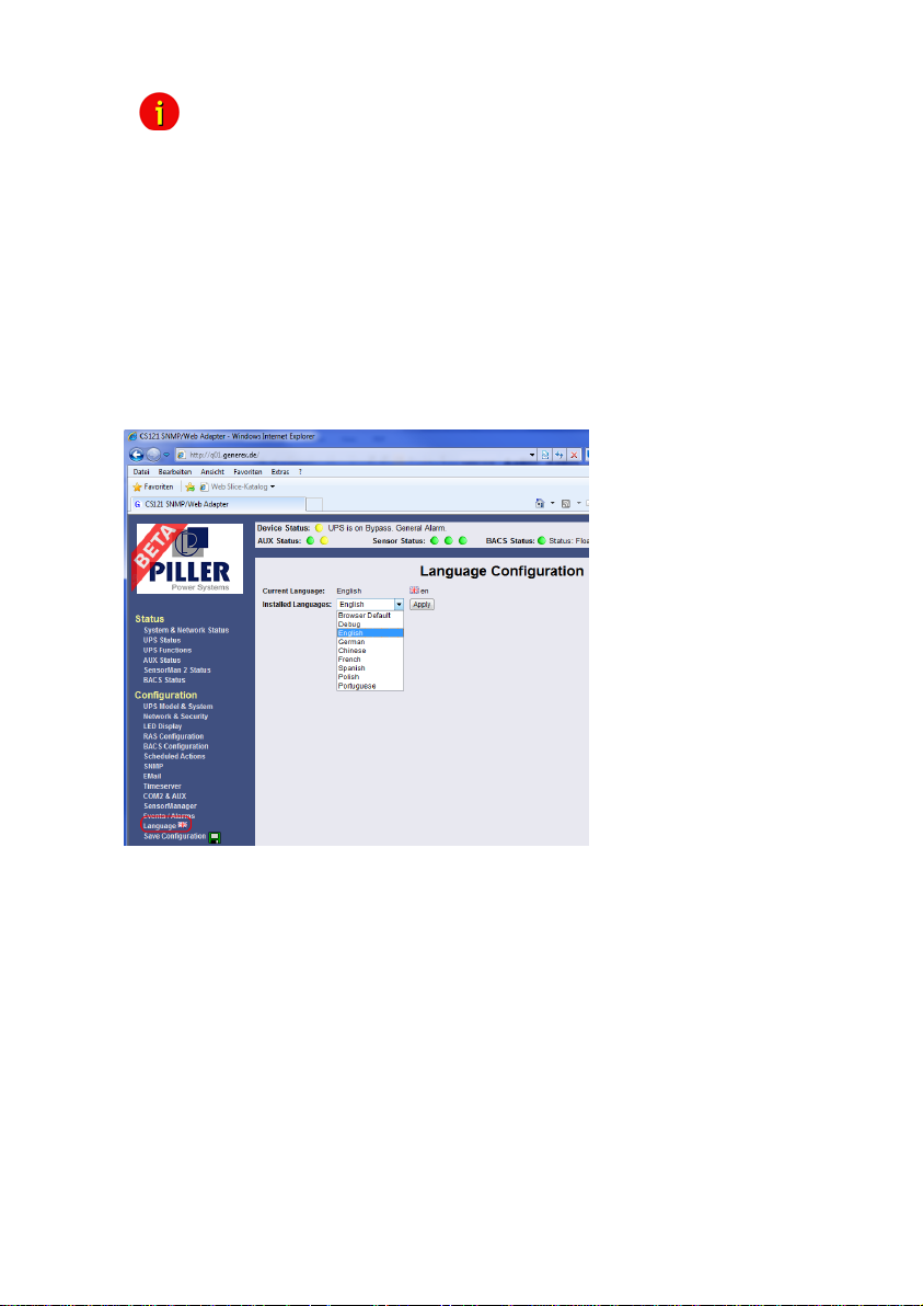
Figure 27: Language Configuration
To be able to use this feature, it might be required, to configure the following into your webbrowser (example Internet Explorer 8) :
- Open the Tools/Internetoptions menu into the IE8
- Click the « Language » button
- Add the languages you use to read websites, listing in order of preference
33
Page 36
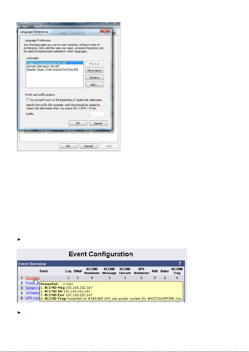
Figure 28: IE8 Internet Options – Languages
4.2.13 Events / Alarms
The Event/Alarm-pages are the main feature of the CS121-configuration and are based on a
combination of events and actions (resp. Jobs). At CS121 there are various events defined,
such as e.g. “Powerfail”, “UPS Battery bad”, “Battery low” etc. Each event the CS121 allows
you to release one or more actions. An action can be e. g. write a log file entry in the alarm log
(as default all events do perform a log file event), to send an email or to perform an RCCMD
Command (e. g. shutdown signals to several RCCMD clients). For a short introduction into the
handling of events and actions see also the section “Quickstart”.
In this menu the relationships between system events such as alarms and the actions to be
taken those events are defined.
To configure your events and actions open the menu “Events / Alarms”. The menu “Event
Configuration” displays an overview about the events and the number of configured actions.
Figure 29: HTTP - Event Configuration with tool tip
Select the desired event and configure it into the event editor.
34
Page 37
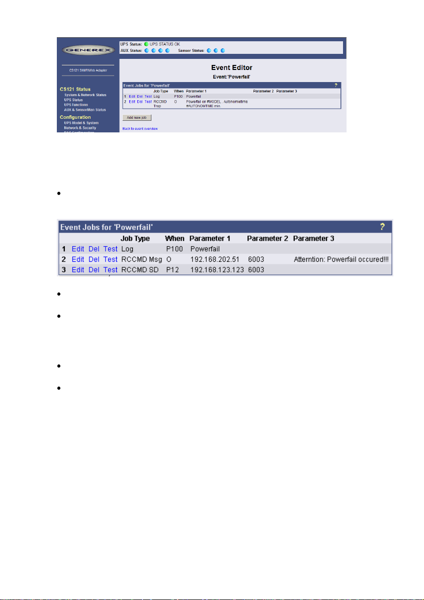
Figure 30: HTTP - Event Editor
The Event Editor allows you to edit, delete and test existing events, as well as to add a new
event job. Please click on the desired action to enter the Job Editor, who lets you make the
configuration.
Here in the following a short example how to configure an RCCMD shutdown signal.
Generally, the event “Powerfail” (in same environments also named “Backup mode”) should
be used to enter the RCCMD shutdown commands, where required with a delay (“do after”) or
depending on the remaining time.
Figure 31: HTTP – Event Editor, Example of a Shutdown-Configuration
Additionally, all Actions of the Event “Powerfail” should also be entered in the Event “Battery
low” whithout any delay.
The Event Editor offers you 3 commands on each job: Edit, Delete and Test (see figure
above). Please note: The Test will perform the execution actually, which means for exeample,
that testing a RCCMD shutdown job will actually trigger the shutdown signal at the client side!
You should perform a shutdown test not until you have switched off the shutdown procedure at
the client (RCCMD Configuration, Button Configure shutdown).
All jobs are not saved until you executed the Save, Exit and Reboot function, not until the
device is restarted and running in normal mode (DIP-Switch 1 is ON).
The number of jobs per event ist limited. CS121 Series 2001-2006 allow up to 25 jobs,
running under Firmware 3.5x even up to 35 jobs (approx., depends on the jobs). If more jobs
should be executed, you have to configure RCCMD as relay station, as described in section
6.1.1.
4.2.13.1 Threshold Events
Some UPS models allow you to configure thresholds for releasing UPS specific threshold
events individually. The CS121 also supports these features, if the UPS includes this option. In
this case, you see at the main event menu “Event configuration” at the bottom an additional
link “Configure threshold events”. Click here to add a new individual threshold event and you
enter the configuration page “Threshold Events”, within you get the possibilities to configure
individual events.
35
Page 38
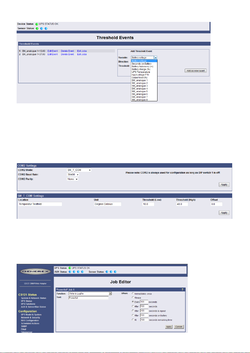
Figure 32: HTTP – Threshold event
The CS121 firmware version 4.27.x or higher provides the option to configure pre-threshold
events for the analog sensor inputs (temperature, humidity etc.) additionally. In this example a
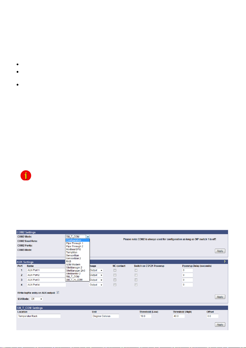
pre-threshold alarm for a SM_T_COM temperature sensor for the value temperature low of
13°C and temperature high of 37°C were defined. The analog values for external sensors are
configurable through the variable SM_analogue 1-8. The proper threshold events for
temperature low of 10°C and temperature high of 40°C were defined into the menu “COM2 &
AUX” for the SM_T_COM.
Figure 33: HTTP – COM2 Threshold events SM_T_COM
4.2.13.2 Logfile Entries
For a numerous of events logfile entries are already pre-configured as default. To configure a
new logfile entry, type in the field “Text” the desired message you wish to enter in the logfile
and choose the option on the right side, when/how often the message should appear in the
logfile.
36
Page 39
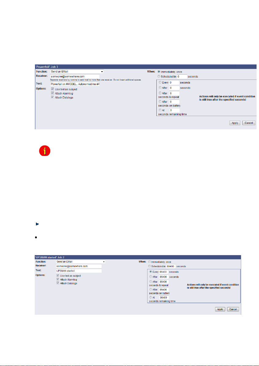
Example above: The text “Powerfail” will written into the logfile every 100 seconds for as long
as the event is present. Other actions on events such as Email, RCCMD shutdown, UPSDialer, TempMan etc. can be configured in the same way. Each event may have an unlimited
number of actions (executed now, delayed etc.).
4.2.13.3 Email-Job
Figure 34: HTTP - Job Editor: Logfile entry
Figure 35: HTTP - Job Editor: Email-Job
To configure an Email-job follow the entries in the figure above.
Note: Please assure that your Email settings in the menu “Email” are valid.
Beside text entries (up to 511 signs), variables can also be integrated into the email from the
CS121. This may personalize your emails. A list of available variables are documentated in the
appendix. Please note, that the variables are only getting filled, if the event actually occurs, not
by testing the action (so a simulation is not possible, you have to create a real alarm to see the
full message).
For example please see the figure above: There, the variables #MODEL and
#AUTONOMTIME will be substituted with their current values, when the action will be
released.
Please notice the syntax, that each variable name must be started with the character # and
must be ended with a <space> character.
Apply your settings and test the Email-job in the “Event Editor” to ensure Email will be
sent.
Continuous, periodic events:
To define an event job, which will be executed continuous, e. g. daily, create a job for the event
„UPSMAN started“ like in the following figure:
Figure 36: HTTP - Job Editor: Continuous event job
4.2.13.4 Email-To-SMS
In order to send a SMS message in case of an alarm, you have to use the “Email to SMS
Service” of your GSM provider. This is a service where the UPSMAN sends an email to the
37
Page 40
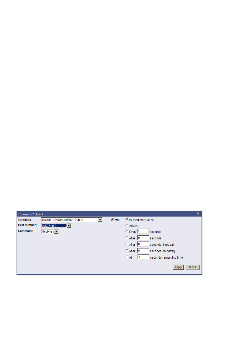
service center of your GSM provider, who converts the email into an SMS. This service is
standard in most GSM networks and very reliable compared to modem solutions. For receiving
emails as SMS you have to contact your GSM provider to open this service. In the following we
describe how this works with some GSM providers in Europe, since these providers change
this very often, please refer to the website of your GSM provider to find out how “Email to
SMS” can be activated for your cell phone.
Example:
GSM Provider T-Systems D1
Your D1 email address will be [email protected] (e.g.:[email protected]) Please
note that you enable receiving emails on your cell phone. This is done by sending a SMS with
the message “OPEN”, to the number 8000.
Only the subject or the text field of the email will be transferred as a SMS, 160 characters from
the subject and text field.
Important: If you want to stop receiving emails, please send a SMS to the number 8000, with
the text “CLOSE”.
(If you want to enable the email transfer again, just send a message to the number 8000,
containing the text “OPEN”, as described before.)
GSM Provider Vodafone
In germany the vodafone email-to-SMS server is called „vodafone-sms.de“. Please take a look
onto the vodafone website of your country for the accordant server name.
Please note that you enable receiving emails on your cell phone. This is done by sending a
SMS with the message “OPEN”, to the number 3400.
Only the subject or the text field of the email will be transferred as a SMS, 160 characters from
the subject and text field.
Important: If you want to stop receiving emails, please send a SMS to the number 3400, with
the text “CLOSE”.
(If you want to enable the email transfer again, just send a message to the number 3400,
containing the text “OPEN”, as described before.)
Other providers
Please ask your cell phone network provider for informations about the email to SMS settings.
4.2.13.5 AUX-Port
Figure 37: HTTP - Job Editor: Switch AUX-Port
In general, the AUX port is used for auxiliary contacts that can be configured to function as
either an Input or an Output (e. g. as input for air-conditioning alarm contacts and as output to
switch on electrical sockets or start beepers etc.). When these contacts are set as inputs, they
are to be treated as an event in the „Events settings“ menu. Reverse, the AUX contacts to be
treated as actions, when they are being used as outputs. The AUX port is also used for
connecting an SS4/AUX power outlet manager, in which case all AUX ports function as
outputs. For the AUX we provide several “add-ons” like the SS4AUX, SM_IO Relay box,
SM_BUZZ alarm beeper, etc. For a complete overview of “add-ons” for the AUX please see
38
Page 41
the according datasheet, downloadable from www.generex.de. We recommend the usage of
our connection terminal CON_AUX for inputs and our CON_R_AUX for incoming and outgoing
alarms (outputs).
The CS121 L (external box) allotted from serial number 0121-10417 (delivered from
31.07.2008) about a COM3 port. The CS121 SC (slot card) allotted from serial number 012309428 (delivered from 03.09.2008) about a COM3 port too. The AUX port assignment is
depending to the hardware type different.
4.2.14 SNMP
Within this menu you can define access controls for SNMP-communities. This concern e.g.
SNMP-Management tools, Trap receivers etc... The CS121 firmware version 4.44.x provides
SNMP V3. SNMP V3 requires the definition of at least a SNMP V3 user on both sides (CS121,
SNMP-Management tool). The following SNMP V3 security level are at present:
o No auth, no priv: No authentication, no privacy, but an SNMP V3 user
o Auth, no priv: Authentication (SNMP V3 user, SNMP V3 password), no
privacy
o Auth, priv: Authentication (SNMP V3 user, SNMP V3 password), SNMP
privacy password
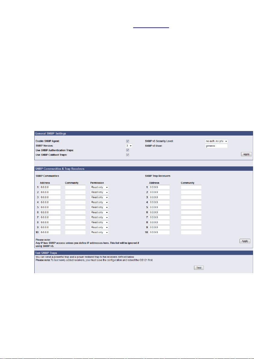
Figure 38: HTTP – SNMP Settings
The submenu displays a column of 10 manager IP-addresses with the corresponding access
permissions, the commands and an example. Use this screen to specify which managers have
access to the SNMP adapter agent, the community names (password) and also what type of
access the IP managers have - read only or read and write.
Please use the following security algorithms in your SNMP management:
- Auth Algorithm = MD5
- Privacy Algorithm = DES
39
Page 42
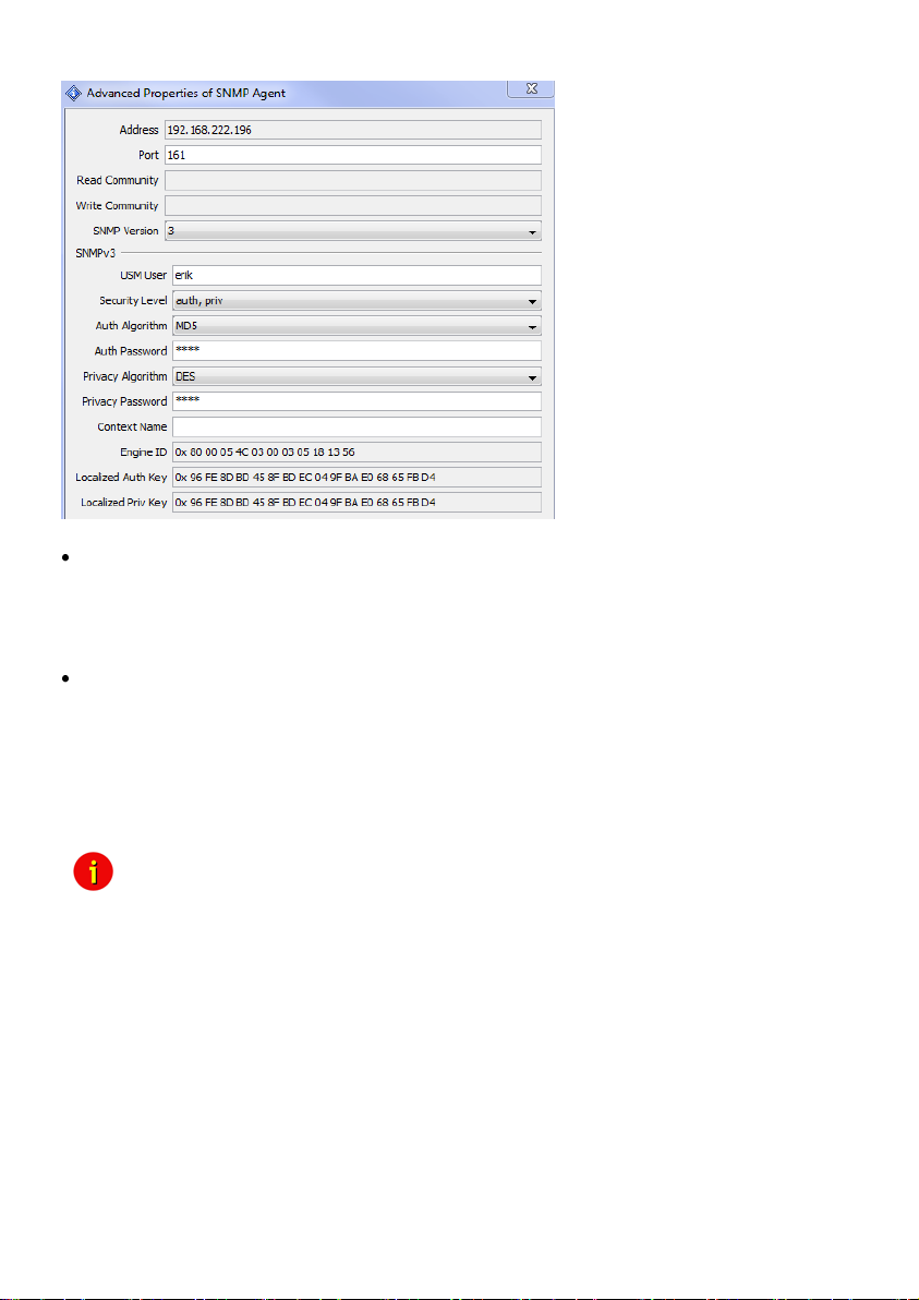
Figure 39: HTTP – SNMP Algorithms
Configuring Trap-receivers
Use this to determine which IP managers receive traps (messages) from your SNMP-adapter.
The screen permits you to send traps about your UPS to IP-addresses (managers).
Also, the menu for switching authentication and cold boot traps are located here. If activated
these traps are send to the configured SNMP trap receivers in the trap receiver list.
SNMP Trap Test
In this menu the user may test the SNMP traps, whereas the defined traps are only used for
test purposes and do not represent real traps. The receiver must also be configured in order to
make this test work. Additionally, save the settings and reboot your CS121 before testing the
communication with the configured IP-address. (does not work in configuration mode). If you
use SNMP Test trap, you will receive SNMP Traps of a “Powerfail” and “Power restored “
scenario – the simulation of a power outage of some seconds.
Note: If you use SNMP polling to retrieve data from the CS121, you should
disable the MODBUS port to avoid interrupts and performance slow
down.
The CS121 can be monitored via web-browser, UPSView, MODBUS, PROFIBUS, LONBUS,
Email and SNMP (e. g. NAGIOS). The RFC1628cs121 SNMP MIB is at present.
The installation and setup of a SNMP browser is described into the Appendix.
To be able to connect to the UPSMAN via SNMP you have to install and configure the
Windows SNMP service.
Open the Windows Components Wizard (click Start, Control Panel, double-click Add/Remove
programs and then click Add/Remove programs again). In components, click Management and
Monitoring Tools (but do not select or clear its check box) and then click Details.
Select the Simple Network Management Protocol check box and click ok.
40
Page 43
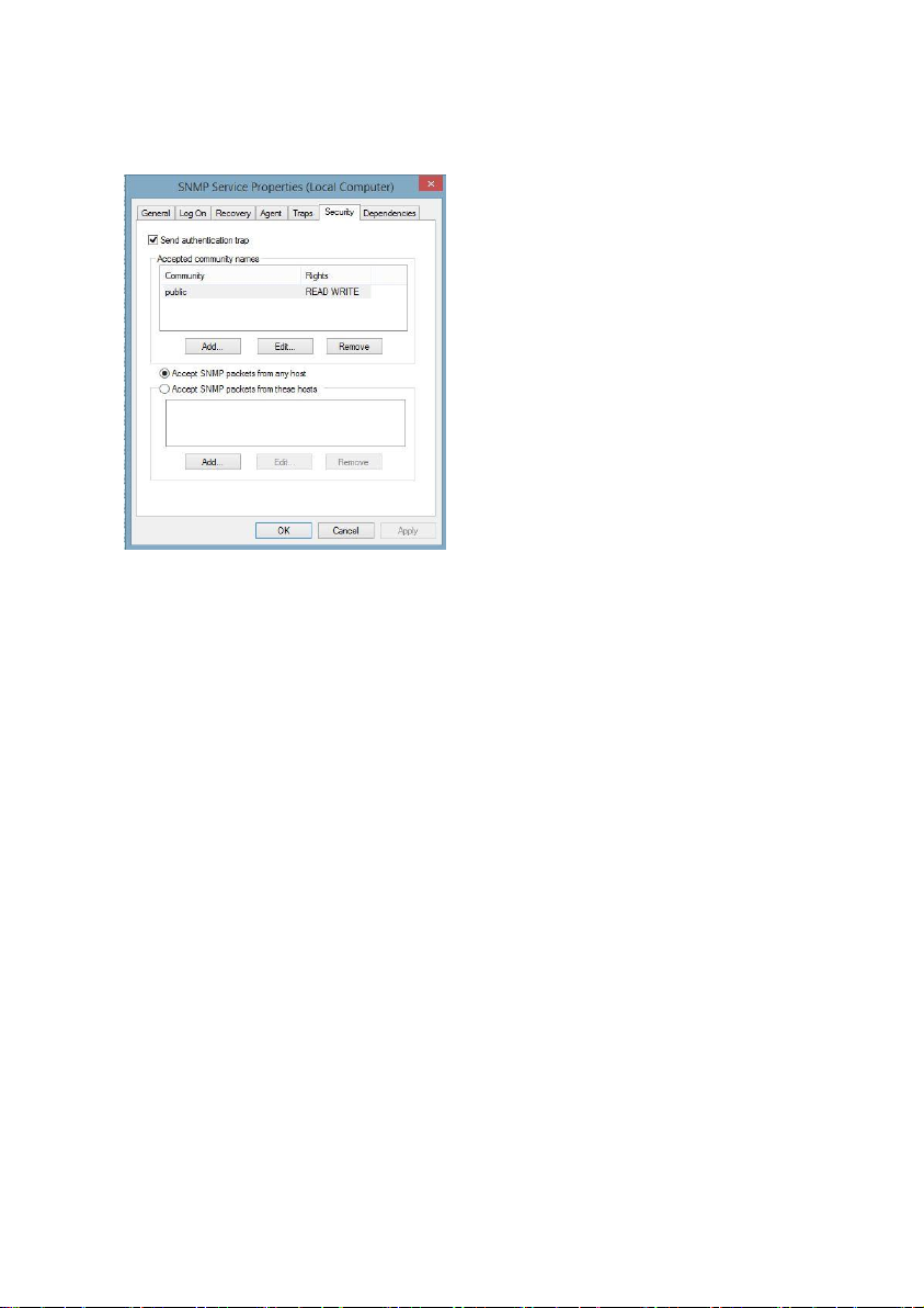
After the SNMP service has been installed you have to configure the SNMP service via the
control panel icon Administrative Tools/Services. Enter the community string of your
management station and the address of the trap target and enter the system group.
Enable the „Accept SNMP packets from any host“ feature.
Start the SNMP-service from the command line by net start snmp or start with the help of the
icon Services from the control panel. If the installation has been completed successfully you
should receive a cold boot trap on your management console. In addition you can access system group data.
MIB-Integration into your NMS
Standard-NMS Installations require for each device to be monitored its specific MIB
(Management Information Base). To monitore the CS121 the Standard-MIB for UPS-systems,
RFC1628, is generally to be integrated into your NMS.
To identify CS121 adapters in your network you may use the MAC address. The MAC address
of every CS121 adapter starts with 00-03-05-02-XX-XX, whereas this address can be found in
the Telnet menu (menu: IP address, gateway address, MIB system group).
Your SNMP adapter is now installed and fully functional. Please read the following for
configuration and functionality descriptions of the adapter.
The MIB is to be loaded onto each SNMP Management Station that is monitoring an UPS via
an UPS SNMP Agent. The MIB determines which UPS parameters can be monitored and
controlled with the SNMP commands „get“ and „set“.
To complete the SNMP adapter installation and configuration process, you must compile the
necessary MIBs to configure the NMS. Any NMS with a MIB compiler can manage the SNMP
adapter.
Perform a „get" and a „set". If the get or set command fail, check the SNMP adapter access
control. The manager must have read permission to execute a get command and read / write
permission to execute a set command successfully.
For instructions on how to compile MIBs for the most popular NMSs - Novell's NetWare
Management Station, Hewlett-Packard´s OpenView Network Node Manager, and SunConnect;
SunNet Manager; see the corresponding heading below.
Figure 40: SNMP Service Properties
41
Page 44
Please note that the CS121 uses the standard MIB, which is included in most SNMP software
already. This MIB is called UPSMIB and corresponds with the Standard RFC1628. In most
cases compiling of the MIB is not required as it can be found under:
iso.org.dod.internet.mgmt.mib2.upsMIB
Please check your MIB directory before compiling the RFC1628!
Configure the NMS
Set/compile the device MIB, if there is no standard UPS MIB RFC 1628 (CS121 only!)
Add the SNMP adapter object to the management map and configuration of the events (e.g.
message to the operator)
Ping the SNMP adapter
Due to the different compilation procedures of the SNMP software products, it is not possible
to explain the general procedures in greater detail. The compilation of a MIB file is explained in
the general SNMP software manuals. Please contact the support, if you cannot resolve errors
using this manual.
After the compilation the UPS software can be polled via a MIB browser and data can be read.
Please choose the corresponding MIB variable or string of MIB variable and set the destination
address TCP/IP of the adapter. The adapter will answer with the UPS data.
Alternatively the Windows UPSMON, JAVAMON or the UPS SNMP WATCH of the DataWatch
Pro Software can be used. The UPS data will then be displayed graphically and internal UPS
information, which are only useful to the technical support, will be hidden. In addition to this,
the UPS SNMP WATCH is able to manage groups of UPS devices, in order to manage parallel
redundant UPS systems.
As an optional add-on for the HP OpenView software, a snap-in may be ordered for
UPSMAN/CS121.
which are present at this UPS or other device. Missing data does no longer cause a return
Note: SNMP response changed: Now only those SNMP requests are answered,
value "0" or "-1". An SNMP Walk will now no longer return any OIDs, which are not supported
by this UPS.
4.2.15 COM2 & AUX
4.2.15.1 COM2
This menu takes the user into the submenus for the general settings of the COM2 and AUX
connection ports of the CS121-adapter.
42
Page 45
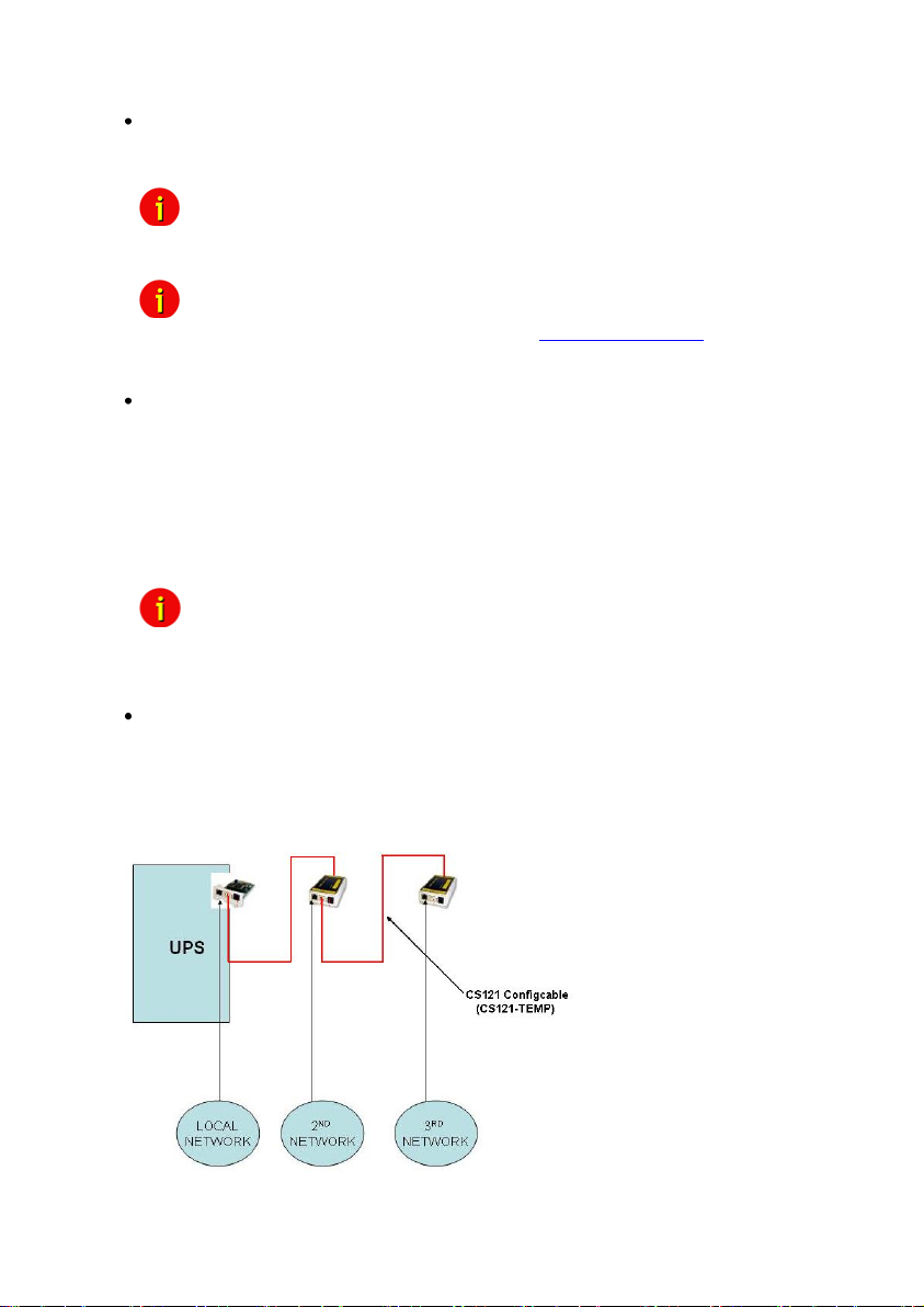
Configuration Mode:
This sets the normal configuration mode for using the CS121 configuration cable (not
included).
Figure 41: HTTP - COM2 Mode overview
Note: Unless DIP-switch 1 is OFF the COM2 port is always running in
Note: The Pipe Through Modes are not supported from every UPS model.
Pipe-Through Mode 1:
Enable or disable the “pipe-through” of the adapter. If enabled, the RS-232 protocol of the UPS
will be transmitted to the COM2 of the adapter, so now you can connect any other RS-232
software to the adapter to make use of the RS-232 UPS protocol – parallel to the adapter. This
makes the use of multiplexer hardware is no longer necessary. 2 serial interfaces on your UPS
which are working parallel are utilized now. Reminder: If you have enabled this function, you
can no longer configure the adapter via the serial cable, you must change the settings via
HTTP. As communication cable between CS121 and your application you have to use the
original CS121 configuration cable (not included).
Note: Please note, that it is required to define the same baud rate of the UPS
Pipe-Through Mode 2:
Analog to Pipe-through mode 1, the UPS data is piped through to COM2 but not directly. In
order to accelerate the internal processes of the adapter, the UPS data is accumulated into
memory before being made available to COM2. Consequently, Pipe-through mode 2 also does
not provide for the relaying of signals to the UPS through COM2 either. (See also section
“Network & Security Settings”)
configuration mode.
Please contact GENEREX via [email protected], if your UPS model
is supporting these modes.
baud rate in “COM2 Baud Rate”. This is valid for Pipe-Through Mode 1 +
2!
Figure 42: Pipe Thru Installation
43
Page 46
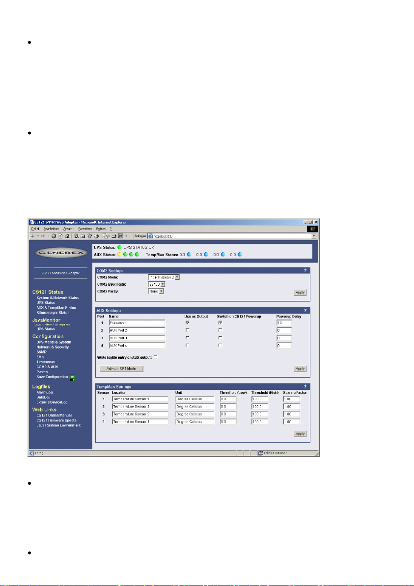
MODBUS/SPI3
The selection of MODBUS/SPI3 in the drop down menu of the COM2 settings enables the
CS121 MODBUS/SPI3-Profibus function. The default CS121 device types communicating
MODBUS via RS232. The special CS121 device types LM and SCM communicating RS485
via the COM2. You can detect by means of the CS121 serial number 0124-..., if you got a
CS121 with RS485 interface. The CS121_SPI3 Profibus and LONBUS converters will be
connected to the COM2 with RS232 port and as configuration use MODBUS/SPI3.Please take
a look into chapter 6.7 for further information.
TEMPMAN & SENSORMANAGER I & II:
The TEMPMAN and SENSORMANAGER are extensions to the CS121 that connect to COM2
of the adapter. The newer of the two products is the SensorManager. These devices are
simply plugged into the CS121 for setup and the only mandatory change on the adapter to
enable this functioning is to set the COM2 Settings to either TEMPMAN or SENSORMAN. The
configuration is easily achieved via the HTML page of the CS121 web server. Please note the
drop-down menu and entry fields on the page. (see screenshot above) For in-depth
SENSORMANAGER settings see following up chapter.
Figure 43: HTTP - COM2 & AUX with TEMPMAN
RAS-Mode (not supported after 2011)
The selection of the “RAS”-entry in the drop down menu of the COM2 settings enables the
CS121-RASManager function. This function is only operational if a RASMANAGER ist used
(CS121 with inbuilt modem) and a RASMANAGER license key is provided (optional, part of
RASMANAGER). While it is also possible to select this entry in the Telnet menu, it is only
possible to configure the RASMANAGER settings using the HTTP interface of the CS121. See
menu “RAS Configuration” for further settings.
GSM Modem
44
Page 47

A GSM modem provides the notification or rather forwarding of the UPS events/alarms via
SMS. Please take a look into chapter 6.5 for further information.
SiteManager 2, SiteManager 2/v3
The selection of SiteManager 2, SiteManager 2/v3 enables the communication between the
CS121 and the SiteManager. The SiteManager is a professional facility management device,
which provides 8 configurable analog inputs, 8 digital inputs and 8 switchable relay contacts.
Please take a look into the SiteManager II user manual for further information.
SiteMonitor 2
The COM2 selection SiteMonitor 2 enables the communication between the CS121 and the
SiteMonitor 2. The SiteMonitor 2 is a professional facility management device, which provides
64 digital inputs for several contact detectors.
SM_T_COM
The SM_T_COM is a temperature sensor for the CS121 and is used for the monitoring and
controlling of UPS rooms, server rooms etc.. Please take a look into chapter 6.2 for further
information.
SM_T_H_COM
The SM_T_H_COM is a temperature and humidity sensor for the CS121 and is used for the
monitoring and controlling of UPS rooms, server rooms etc.. Please take a look into the
SM_T_H_COM datasheet for further information.
4.2.15.2 AUX and SITESWITCH4 Settings
The AUX connection is an input/output port for connecting external contact devices such as
alarms or for connecting to an SS4AUX SiteSwitch power socket manager. The SS4
SiteSwitch is a standalone device with a built in CS121. The SiteSwitch SS4 AUX is an
inexpensive and practical extension to the CS121 adapters enabling the individual power
switching of up to four power sockets – using the inbuilt AUX port (4 pins) of the CS121. By
entering the corresponding list number, the AUX ports are switched to output or input.
The AUX port can only read signals, if the port is switched to input. If switched to output the
AUX port can send signals to an optocoupler for example. (Refer to the circuit diagrams in the
appendix.) After a reboot, the state of the switches remains in the status previous to the
reboot.
The following describes the configuration of the AUX ports using the HTML interface. All of the
AUX ports 1 – 4 can be manually set to „Output“ so that in the event of an alarm, the CS121
can be preconfigured in the “Events” menu to switch the ports individually. When all ports are
set to “Output”, this is equivalent to activating the „SS4 Mode“. The SS4 mode is to be
activated when connecting a SITESWITCH4 to the AUX port of the CS121.
When the Output options are deactivated, the AUX ports act as inputs used for monitoring
signals such as input from alarm contacts. For example, while configuring port 2 as an input to
monitor an alarm, the CS121 can also be preconfigured to respond to the alarm signal from
port 2 to shut on or off a device connected to one of the other ports that has been set to
Output.
For example see also the settings in figure “HTTP - COM2 & AUX” above.
The OUTPUT setting is to be configured with a power-up sequence so that, for example the
fileserver on port 1 will be switched on upon Power up. In the Power up delay-fields the
number of seconds after a Power up in which a connected port device is to be switched on can
be entered. E.g. the setting 10 in the Power delay column will cause the switching on of the
fileserver on Port 1 to be delayed by 10 seconds after the Power up. Note that executing the
Save, Exit & Reboot does not cause a Power up, in order to cause a Power up the power
supply to the adapter must be interrupted. The differences between a Reboot and a Power up
become more noticeable when considering the AUX port contacts. During a Reboot the current
45
Page 48
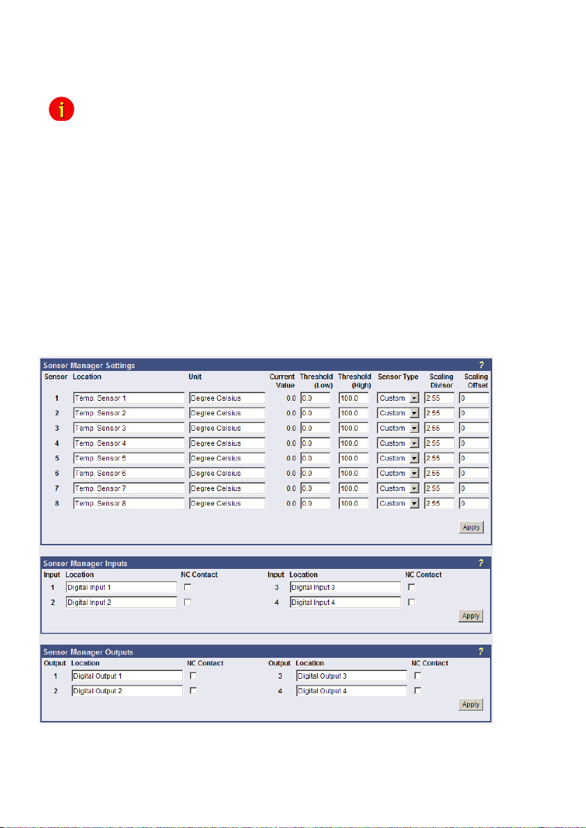
status of the ports remain unchanged unless the settings of the ports have been changed from
input to output or vice versa. A Power up will set the ports to the preconfigured Power up
settings.
Note: From CS121 HW131 it is required, if the AUX ports will be defined from
4.2.16 SENSORMANAGER
The SENSORMANAGER is a data measurement and collecting unit which allows the
individual measurement and monitoring of 8 analog measurement devices (0-10V) and 4
digital alarm inputs or 4 outputs (open collectors). SENSORMANAGER has its own chapter in
the manual, wherein the features and field of applications etc. pp. are described as well as in
depth the various specific configurations.
In generally, the SENSORMANAGER unit is connected with its COM 1 port to CS121’s COM 2
port, which has to be configurated as SensorManager mode.
Within the configuration page “Sensor Manager Settings” of the CS121 you can - among
others - define limit values when events (to be configurated in “Events / Alarms”) will be
released.
“Unused” to In- or rather Output, that a cable with Pull-Down resistance
or a CON-AUX or a CON-R-AUX is connected. Otherwise the status
display of the AUX ports is undefined and can be changed by itself
anytime !
Figure 44: HTTP – Sensor Manager Settings
Please see SensorMan in section “Accessories” of this manual.
46
Page 49
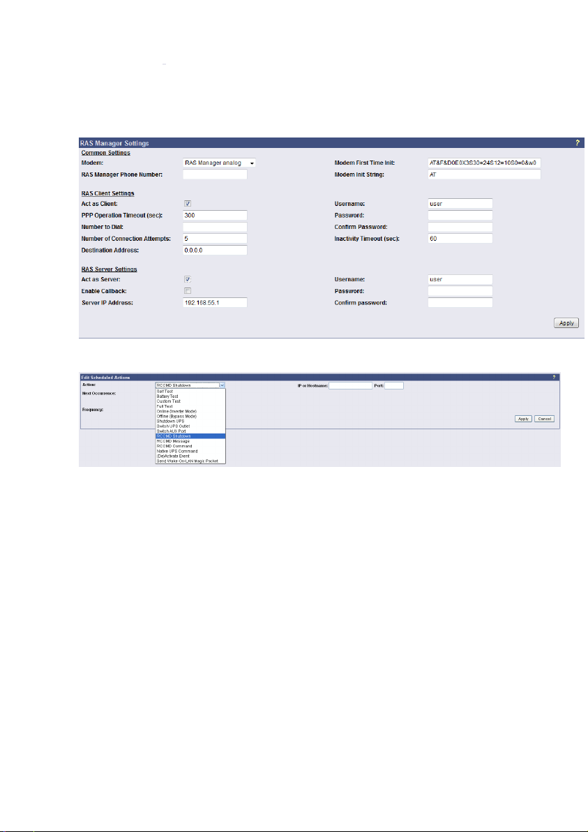
4.2.17 RAS Configuration
This is the standard setting for the RASManager, the CS121 with the built-in modem. Most of
the CS121 products can also have the RASManager feature enabled by purchasing PPP
License Key and by connecting a supported modem. The RASManager, RASControl Software,
the UNMS II Software with the TeleService Module come with an extra user manual for
describing this feature.
Figure 45: HTTP - RAS Manager Settings
4.2.18 Scheduled Actions
Figure 46: HTTP – Scheduled Actions
In the “Scheduled Actions” menu you can schedule the following actions:
Self test: A self test is a short hardware test, which switches the device to a short discharging.
Battery test: A battery test is a short battery test, which switches the battery to a short
discharging.
Custom test: A custom test checks, if the batteries are able to hold the downtime at least.
Full test: A full test is used to calibrate the UPS and will discharge the batteries till the „battery
low“ limit. This test should be done once a year at most, because to avoid a damage of the
batteries.
Online (inverter mode): This is a function to switch into “Normal Mode” (power supply of the
battery). This status is the normal UPS mode and it is actual not necessary to schedule any
kind of commands.
Offline (bypass mode): This is a function to switch into “Bypass Mode”. Thereby the inverter
of the UPS is not in usage and the current would not be buffered, if a failure would occur. This
mode displays a failure of the UPS, please call the UPS service to solve the problem.
Shutdown UPS: This action causes the switch off of the UPS. This could be arranged, if a low
charging of the battery occurs, in case of a fire alarm or a power failure happens.
47
Page 50

Switch UPS Outlet: This is a function to switch of the UPS outlets (not provided of every
UPS).
Switch AUX port: In general the AUX port is used for additional contacts, which can be
configured as in- or output (e. g.: as input for alarm contacts of an air conditioner or as an
output to switch a connector). If the contacts will be configured as inputs, they are able to be
used as event in the “Event Settings”. Additionally you can establish jobs, if they are
configured as outputs. The menu “Switch AUX port” is for outputs only. You cannot switch
inputs!
RCCMD Shutdown: Here, IP-addresses from computers with RCCMD connection (receivers)
in the network can be entered. The CS121-adapter can then initiate a multi-server shutdown.
The timing for such a shutdown procedure depends on the configured down time of the
adapter (default: time of the remaining capacity of battery in min., during a long power fail.) or
on a countdown timer. Extended CS121-adapters can also use more events (e.g. battery low,
battery defect, communication lost etc.) as RCCMD signals. Please contact your UPS dealer
for more information.
RCCMD Message: With this job the user can combine and configure a text message with
RCCMD event. Text messages can be sent to RCCMD receivers. This makes it possible to
send text messages via RCCMD (version 2 or higher) to a Windows 2000 server or a Unix
computer, using the “NET SEND” or the respective “WALL” method. The problem with notifying
network users on different operating systems is therefore solved.
RCCMD Command: This RCCMD signal will cause any RCCMD receiver (e.g. another
CS121, RCCMD client or SITEMANAGER, SITESWITCH4) to execute a command or
program, e. g.: to start a program at a remote work station.
Native UPS Command: (for very experienced users only) This is a function to execute UPS
own commands. Assumption: The user knows the “Command IDs” and the proper parameter.
These commands require additional parameter. If you want to use these kind of commands,
just contact your UPS dealer.
(De-) Activate Event: This is a function to switch off appointed events/alarms.
Send WOL: WOL stands for “Wake on LAN”. This function uses data packages to prompt
other computers in a local network to start-up. Please use this function in the event “UPSMAN
started” to wake up computers which have been shut downed previously after an extended
power outage, which cause the CS121 or UPS to switch off completely. Additional you may
add this WOL signal to the EVENT “Power restored”. Advice: Not every network cards are
providing this function or are password protected. Activate this function into the BIOS settings
of the motherboard.
Send Periodic Email: This is a function to send the log files via email periodically (from
firmware 4.xx and higher).
4.2.19 Save Configuration / Reboot
If you are satisfied with your configuration select “Save, Exit & Reboot” and wait until the
adapter informs you about the reboot-process. Do NOT close your web-browser!
4.3 Reading the Logfiles
The CS121-Alarmlog contains the alarm protocol of events that were designated as alarms in
the Event/Settings-section and include the user defined alarm settings of the CS121
configuration as well as the events that are designated as alarms in the UPS native protocol.
These entries include such things as CS121 Admin defined email notifications which lead to a
48
Page 51

much higher alarm entry log level than would otherwise be the case if only UPS protocol
defined alarms were being recorded. For explanation, the following illustrates typical log file
entries made by the UPS:
The CS121 logs the time after a new start up:
01/17/2007,16:21:45, Synchronized with timeserver 192.53.103.103. OK
This indicates a successful synchronization with the timeserver.
01/17/2007,16:23:39, UPSMAN <UPS model> has started
UPS communication functions and device is in normal operation mode. This is the standard
entry after every successful reboot of a CS121.
(The following entries result only from user defined settings as with the CS121
ADMINSTRATOR EMAIL Settings.)
01/17/2007,16:28:39, MAIL: subject "CS121 Event 4" successfully sent.
All “EVENT X” designated alarms are viewable in the EVENT list of the web browser. EVENT 4
for this particular UPS is the EVENT "UPSMAN started" – This means that an Email was sent
with the text "UPSMAN started" which acts to confirm the log entry of 08:06:50 as Email.
01/17/2007,16:28:47, MAIL: subject "CS121 Event 16" successfully sent
In this case, the Scheduler has been activated and is ready for operations. In this case, the
scheduler is set to conduct a "Selftest" which it in turn relays per email to the designated
CS121 ADMIN.
01/17/2007,16:28:47,MAIL: subject "CS121 Event 26" successfully sent
01/17/2007,16:29:03,MAIL: subject "CS121 Event 27" successfully sent
01/17/2007,16:29:28,MAIL: subject "CS121 Event 28" successfully sent
01/17/2007,16:30:46,MAIL: subject "CS121 Event 29" successfully sent
These are 4 Emails indicating the status of the AUX Ports (Auxiliary connection for external
alarms), which are set to give notification of the status signal LOW. Since the AUX Status can
only be set to High or Low and given that the CS121 in itself cannot distinguish the device, an
alarm email will be sent by the CS121 to the designated ADMIN at startup per default with the
startup status of each connected alarm. In this case, it is up to the administrator to determine if
the emails indicate an actual alarm or not.
01/17/2007,16:34:48,MAIL: subject "CS121 Event 38" successfully sent
01/17/2007,16:35:12,MAIL: subject "CS121 Event 39" successfully sent
01/17/2007,16:35:16,MAIL: subject "CS121 Event 40" successfully sent
01/17/2007,16:35:28,MAIL: subject "CS121 Event 41" successfully sent
01/17/2007,16:35:33,MAIL: subject "CS121 Event 42" successfully sent
01/17/2007,16:35:40,MAIL: subject "CS121 Event 43" successfully sent
01/17/2007,16:35:51,MAIL: subject "CS121 Event 44" successfully sent
01/17/2007,16:35:57,MAIL: subject "CS121 Event 45" successfully sent
These are 8 Emails sending information about analogue sensors (temperature, humidity and
the like) that are connected to a SENSORMANAGER, indicating that all controlled values are
within tolerance levels - or that no sensor is connected to the device or connection port.
01/17/2007,16:36:30,MAIL: subject "CS121 Event 54" successfully sent
01/17/2007,16:36:41,MAIL: subject "CS121 Event 55" successfully sent
01/17/2007,16:36:48,MAIL: subject "CS121 Event 56" successfully sent
01/17/2007,16:36:57,MAIL: subject "CS121 Event 57" successfully sent
These 4 Emails indicate that the digital sensors (for airconditioning, fire alarms and the like) of
the SENSORMANAGER, are either in the normal state or that no sensor is connected.
01/17/2007,17:41:12,MAIL: subject "CS121 Event 62" successfully sent
01/17/2007,17:41:36,MAIL: subject "CS121 Event 63" successfully sent
01/17/2007,17:43:23,MAIL: subject "CS121 Event 64" successfully sent
01/17/2007,17:44:01,MAIL: subject "CS121 Event 65" successfully sent
49
Page 52
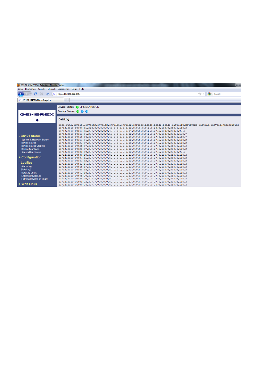
These 4 Emails indicate the status of the digital alarm contacts of the sensors (for Emergency
OFF, fire extinguisher and the like) connected with the SENSORMANAGER, showing either
the status is NORMAL or that nothing is connected.
01/17/2007,17:52:13,MAIL: subject "CS121 Event 70" successfully sent
This Email shows that no SENSORMANAGER is connected although the CS121 is configured
as having a connection to a Sensormanager. This informs the ADMIN that the CS121 is
incorrectly configured. In this case, the user should correct the settings.
The UPS data will be logged with timestamp into the CS121 DataLog.
Figure 47: HTTP – CS121 DataLog
The data of the connected devices (e. g. temperature sensor) will be logged into the CS121
ExternalDeviceLog.
50
Page 53
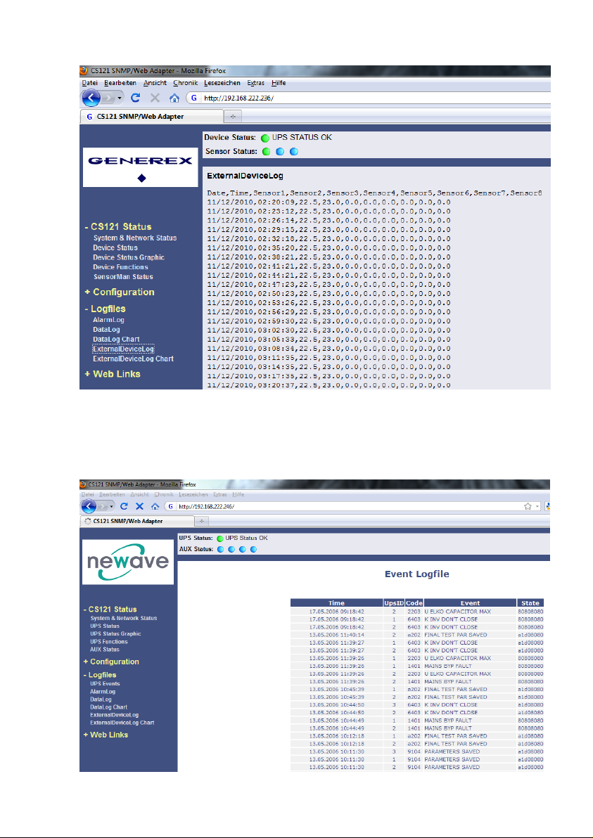
Figure 48: HTTP – CS121 ExternalDeviceLog
In figure 62 the logging of a SM_T_H_COM is displayed, sensor 1 for the temperature, sensor
2 for the humidity.
At unify UPS their events will be imported out of the UPS directly and are displayed into the
CS121 menu LogFiles, “UPS Events”.
Figure 49: HTTP – CS121 UPS Events
51
Page 54

4.4 RCCMD
RCCMD (Remote Console Command) is the world’s most successful shutdown client for
heterogeneous networks and is the most secure way to establish a UPS multiple server
shutdown sequence today. RCCMD clients are listening to an RCCMD server which is usually
an UPSMAN software, CS121 or any third-party UPS manager which has a license to use
RCCMD. An RCCMD server is found inside any CS121 and is triggering RCCMD clients in
case of alarms. Therefore RCCMD requires such listeners on each client-computer you wish to
forward RCCMD signals. For installation of RCCMD at client-side please see the section in
chapter “Add-on software”.
Note: RCCMD clients are optional and not freeware. Most CS121 are
equipped today with a single RCCMD standard license, some UPS
makers add more licenses, other do not deliver any license at all with a
CS121. Contact your UPS maker and ask for the license regulations for
RCCMD in conjunction with your CS121.
4.4.1 RCCMD Jobs
You can define RCCMD jobs into the CS121 menu “Events/Alarms”.
Powerfail
This event occurs, if the UPS will lose the power supply. This event might be the optimal fitting
for the definition of RCCMD shutdowns.
System Shutdown
This event will be triggered, if the defined system shutdown time was reached. This event
should be used for operations only, which will force a shutdown immediately.
Note: This event is the last event, that the CS121 can execute prior of the UPS
shutdown. Do not use this event to execute RCCMD shutdowns, because the remaing time is
not assured! We recommend to use the event powerfail for the RCCMD shutdowns.
Battery low
This event will be triggered from the UPS, if the battery capacity of the UPS has reached a
critical state.
UPSMAN started
This event will be triggered periodical, if the CS121 is in normal operation. You can use this
event, if you want to start actions, which should be triggered into normal operation.
4.4.2 RCCMD Traps
RCCMD traps are “push” messages (like SNMP traps), which will be send from the CS121
automatically to the RCCMD client. The RCCMD traps are text messages only.
If you want to define RCCMD Traps by yourself, you can use the following variables :
#OUTPOWER – Output power in %
#BATTCAP – Battery capacity in %
#INVOLT – Input voltage in V
52
Page 55
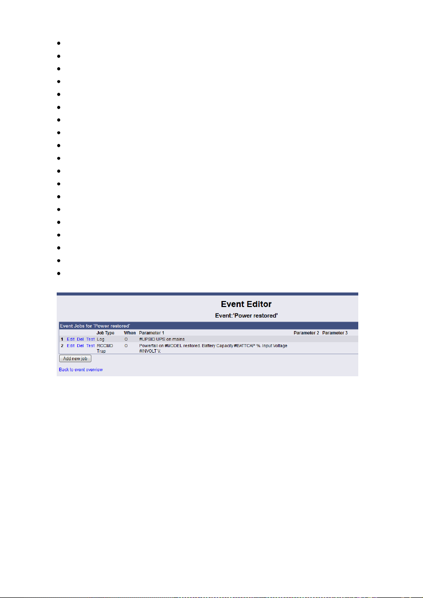
#TEMPDEG – Temperature in °Celsius
#AUTONOMTIME – Autonomy time in minutes
#LASTTSTBUPT – Last test battery autonomy time in minutes
#STATUS – Status
#ISTEST – In test mode
#LASTERR – Last error
#TIMEUNTILSHTDWN – Time until shutdown in minutes
#RUNTIME – Runtime in minutes
#INCURR – Input current in A
#BATTVOLT – Battery voltage in V
#INFREQ - Input frequency in Hz
#OUTFREQ – Output frequency in Hz
#CNT_PF – Counter power failures
#CNT_BL – Counter battery low events
#CNT_SD – Counter shutdowns
#CNT_SA – Counter shutdowns active
#CNT_TF – Counter test failures
#INPHASES – Amount input phases
#OUTPHASES – Amount output phases
Example of the configuration of a RCCMD Trap job for the event “Power restored”:
Figure 50: HTTP - Job Editor: RCCMD Trap, Event « Power restored »
You can add any kind of text/measurement units. It is required to add a blank ahead and
behind the variable (#MODEL). If you want to receive more variables, please seperate them
with a blank and a « . ».
Powerfail on #MODEL restored. Battery Capacity #BATTCAP %. Input
Voltage #INVOLT V.
The RCCMD Trap would be received like that :
53
Page 56
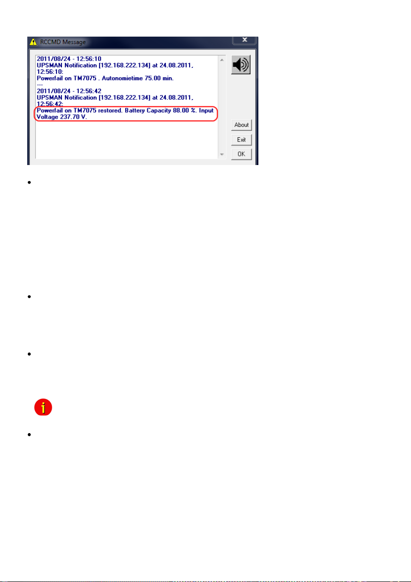
Figure 51: HTTP - Job Editor: RCCMD TRAP
Because the CS121 adapter plays an active roll when executing its actions “Message”,
“Shutdown” and “Command” (that is to say the CS121 -adapter sends an RCCMD-signal to an
RCCMD client), it is necessary, to enter the IP-address in parameter 1, and the port number of
the RCCMD client in parameter 2 (default port is 6003). Additionally, the RCCMD client must
either be pre-configured with absolutely no sender filter or should be pre-configured with the
IP-addresses of the particular UPSMAN servers (like UPSMAN, CS121 or other RCCMD
compatible sender) that are to function as recognized senders. These configurations take
place when installing the RCCMD client service. Further details are in the RCCMD software
documentation.
Attention: At the function RCCMD Command it is required to configure a job for every single
client. It is not possible to request several clients/IP-addresses in one job to execute a
command.
RCCMD also includes the feature “RCCMD Trap”. RCCMD Trap is a method for sending
information to the RCCMD stations which have been applied to the CS121. RCCMD Traps
invokes messages at all RCCMD stations. Because of RCCMD plays an active roll in this
mode no receiver information is to be entered in the parameters of this job (see also following
sections). It is condition to enable the RCCMD Trap control box in the menu “Network &
Security Settings”.
The CS121-adapter uses the parameter-based RCCMD Version 2, which can execute
different actions on the same TCP channel. RCCMD Version 1 clients can only execute one
action (shutdown file execution as default, so any RCCMD signal which is transmitted to an
RCCMD client V1 will cause a shutdown of this server ) RCCMD Version 3 is capable to
handle also redundant UPS installations (eg. PC with 2 power supplies and 2 UPS).
Note: For all 3 RCCMD event functions a list of the user configured RCCMD
receivers appear in every RCCMD event.
The amount of RCCMD clients is limited and dependent of the size of the RAM. 50 RCCMD
clients per CS121 are guaranteed. If you need more than 50 clients to reach, we recommend
to use RCCMD relays (see chapter 5.1.4). However it is only possible to execute 50 clients at
the same time, meaning that the first 50 RCCMD clients are executed followed by the next 50
etc. We recommend to change the timing parmeters of the RCCMD-jobs that always less than
50 commands are transmitted at the same time. We also recommend to use an RCCMD client
as Relaystation if you want to shutdown more than 50 computers from a single CS121. (see
section 6.1.1 RCCMD with SSL for Windows
The Secure Sockets Layer (SSL) protocol is a cryptographic protocol that provides security
and data integrity for communications over TCP/IP networks.
Use your Web-browser to navigate to the address of your UPS Web-Manager. Click the
“Network & Security” configuration button and enable the SSL network feature.
54
Page 57
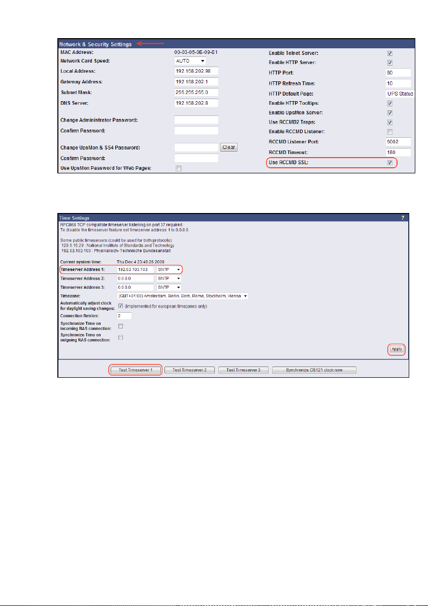
Figure 52: RCCMD SSL Settings
The SSL network feature requires correct time settings, so it is required to configure a
timeserver. Click the „Timeserver“ configuration button and enter the address of at least one
timeserver.
Figure 53: Timeserver Settings
Click the „Save Configuration“ button and the „Save, Exit & Reboot“ button to confirm your
settings.
55
Page 58
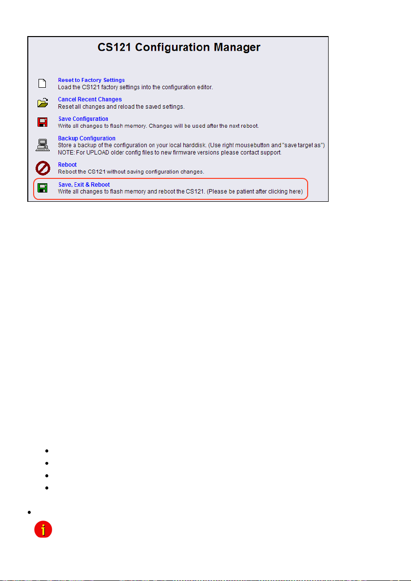
Figure 54: Settings Confirmation
4.4.3 RCCMD with own SSL certificates
In this chapter we will describe, how to use an own SSL certificate with RCCMD, e. g.
OpenSSL ( http://www.openssl.org ):
Be your own CA
Using OpenSSL it is quite simple to become your own CA. Just run:
CA.pl –newca
Done! Just ensure, that you select a useful CN (common name)!
Create your RCCMD certificate
You need to create your certificate for RCCMD now. As it will use it for verification, it should
contain the same useful common name (CN), that you selected for the CA. The private key
must not be encrypted to let the RCCMD Client (service) start without trouble. Therefore we
use the “–nodes” option and the “-newreq” command:
CA.pl –newreq -nodes
Sign with your CA:
CA.pl –sign
Now create an empty file named “rccmd.pem“ and copy the cert information of newcert.pem
(rccmd certificate), newkey.pem (private key) and cacert.pem (CA) into it. Please note, that the
exact copying is required to use it without trouble!
Use your own RCCMD certificate
Do the following steps at the RCCMD Client and every sender (e. g. UPS Web Manager):
Backup the existing “rccmd.pem”
Replace the existing “rccmd.pem” with your own
Restart the RCCMD Client
Restart the RCCMD Sender
RCCMD client as relay station)
56
Note: The RCCMD timeout is 60 seconds, meaning that after this time the
communication to the RCCMD client will be stopped and a logfile entry
Page 59
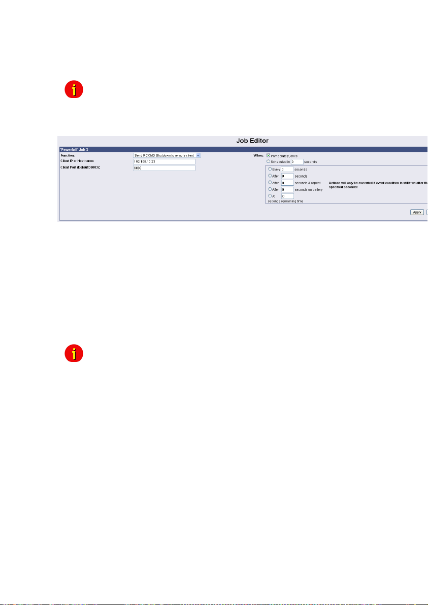
Note: All network components, such as routers, hubs etc. need to be fully
UPS-supported, as it is otherwise not possible to reach all clients during the network
shutdown.
4.4.4 RCCMD Shutdown
Figure 55: HTTP - Job Editor: RCCMD Shutdown
Here, IP-addresses from computers with RCCMD connection (receivers) in the network can be
entered. The CS121-adapter can then initiate a multi-server shutdown. The timing for such a
shut down procedure depends on the configured down time of the adapter (default: time of the
remaining capacity of battery in min., during a long power fail.) or on a countdown timer.
Extended CS121-adapters can also use more events (e.g. battery low, battery defect,
communication lost etc.) as RCCMD signals. Please contact your UPS dealer for more
information.
Please note at the configuration of the timer box, that the time specifications outside the timer
box (Immediately, once and Scheduled in) will be ALWAYS executed. The time specifications
inside the timer box (Every/After seconds, After seconds & repeat, After seconds on battery, At
seconds remaining time) will be only executed, if the alarm/event is still present.
will be made. When an OK response from the client is received, the
system assumes a successful RCCMD Shutdown and proceeds with a
shutdown of the next 50 RCCMD clients. Every minute one batch of up
to 50 RCCMD clients can be executed without SSL.
Note: For security reasons we recommend to make the same RCCMD
In case a connection is established using telnet or http, the RCCMD-
Due to network settings it is possible that this test is answered with
Example for the configuration of a RCCMD Shutdown
Click on the CS121 Web-interface in the menu „Configuration“ the Events/Alarms button.
Select the event Powerfail.
shutdown entries for the Event “Battery low” - but in this Event without
any delays to avoid that the server crashes because of low battery
alarm.
command can be tested without using disrupting power to the UPS. At
the Web-browser you simply have to press “test” to transmit the
shutdown signal immediately. (see figure HTTP - Event Editor above)
"failed". The signal is often sent and received although the receiver may
not respond correctly. In such cases, only use the receiver side to check
if the signal has actually been received. For checking the communication
between RCCMDs you have to check the RCCMD log file on both sides.
In the CS121 the logs are inside the Alarm log, at the RCCMD client side
the logs are found inside the RCCMD folder e. g. rccmd.log.
57
Page 60
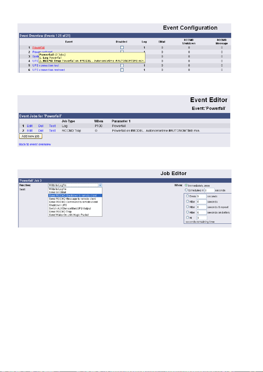
Figure 56: HTTP – Event Configuration
Click the “Add new job” button.
Figure 57: HTTP – Event Editor
Select the function “Send RCCMD Shutdown to remote client” in the Job Editor:
Figure 58: HTTP - Job Editor
Enter the ip-address of the client, that should receive the shutdown.
Description of the scheduler box :
"Immediately, once: Action/Job will be executed in case that this EVENT is true immediately,
only once the Action/Job is started (no repeat)".
"Scheduled in”: Action/Job will be executed in case that this EVENT is true with a scheduled
delay of x seconds. Unregarded if the EVENT is still true or not, after the delay the action will
be started.
The timer settings in the blue framed scheduler box will be executed only, if the EVENT is still
true after the delays/countdowns have run out.
E.g. if any action has been configured at "do after 10 seconds" than this action will NOT be
started, if after 9 seconds the EVENT is no longer true. Only if 10 seconds this EVENT was
present, the action will be triggered.
See below the explanation of all timer event configuration options for this type :
"Always”: Action/Job will be executed in case that this EVENT is true immediately and
repeated always as long as the EVENT is true (every 5 seconds according to poll cycle
default of a CS121).
58
Page 61
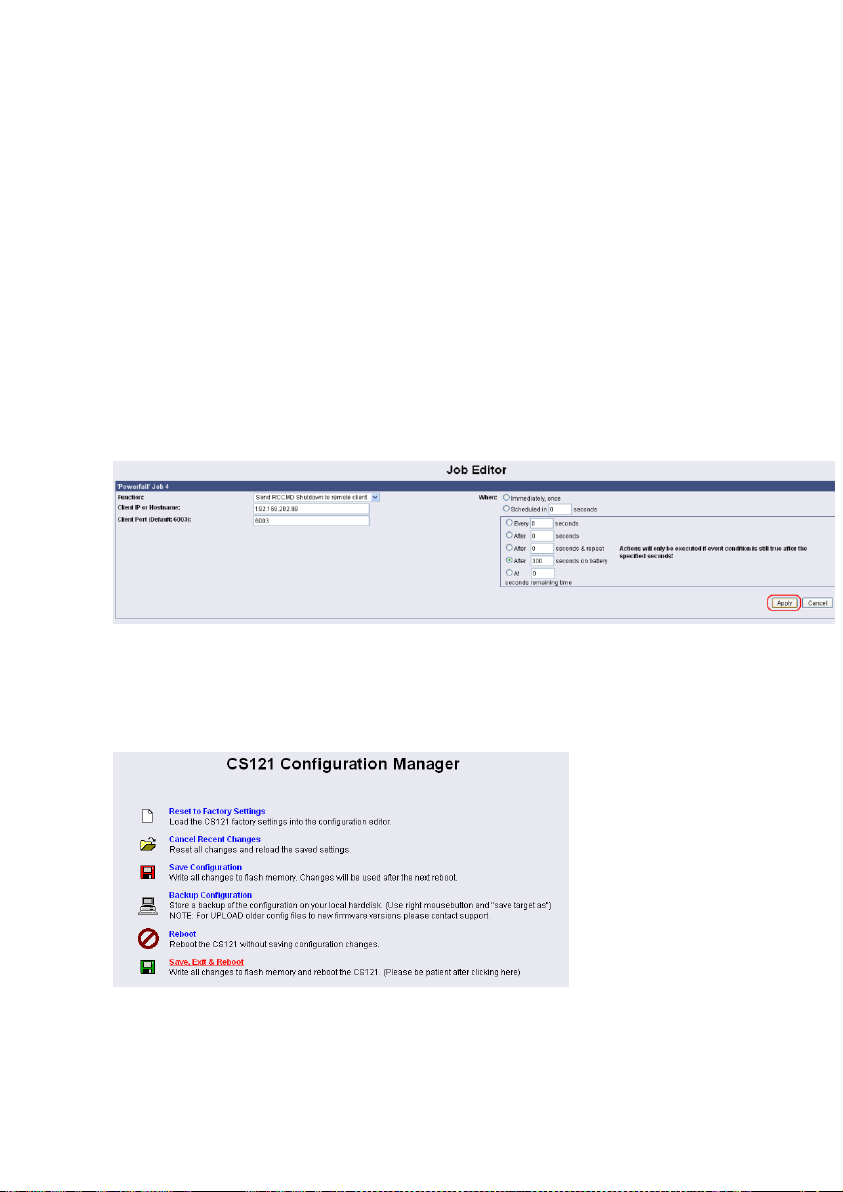
"Every x seconds”: Action/Job will be executed in case that this EVENT is true with a delay
of x seconds and repeated every x seconds again.
"After x seconds”: Action/Job will be executed in case that this EVENT is true after a delay
of x seconds. Action will be cancelled, if EVENT is false before time has run out.
"After x seconds and repeat”: Action/Job will be executed in case that this EVENT is true
after a delay of x seconds and will be repeated after x seconds again. Action will be cancelled,
if EVENT is false before time has run out.
"After x seconds on battery”: Action/Job will be executed in case that the EVENT UPS ON
BATTERY or POWERFAIL is true and after a delay of x seconds. Action will be cancelled, if
EVENT is false before time has run out. This Job is identical to the EVENT POWERFAIL and
the configuration "After x seconds".
"At seconds remaining time”: Action/Job will be executed in case that the UPS runs on
battery/Powerfail and the remaining time, read by the UPS or calculated by the
internal CS121 routine has reached a certain remaining time. Only useful if the
"Autonomytime" of your UPS can be regarded as reliable.
"REMAINING TIME " is defined as Autonomytime in seconds of this UPS at the actual
discharging level minus the DOWNTIME (configured in menu UPS MODEL & SYSTEM,
default is 3/6 minutes).
In this example a RCCMD Shutdown is configured for the event Powerfail. The shutdown
signal should be send after 5 minutes (300 seconds). Click the „Apply“ button after you have
finished the configuration. Save your settings via the menu „Save Configuration“ and execute
the „Save, Exit & Reboot“ function.
We recommend to test the configuration prior of the implementation of the shutdown function
into a live-system. Click into the Event Editor of Powerfail the “Test” button (Job Type: RCCMD
SD).
Figure 59: HTTP - Job Editor / Function
Figure 60: HTTP – CS121 Configuration Manager
59
Page 62
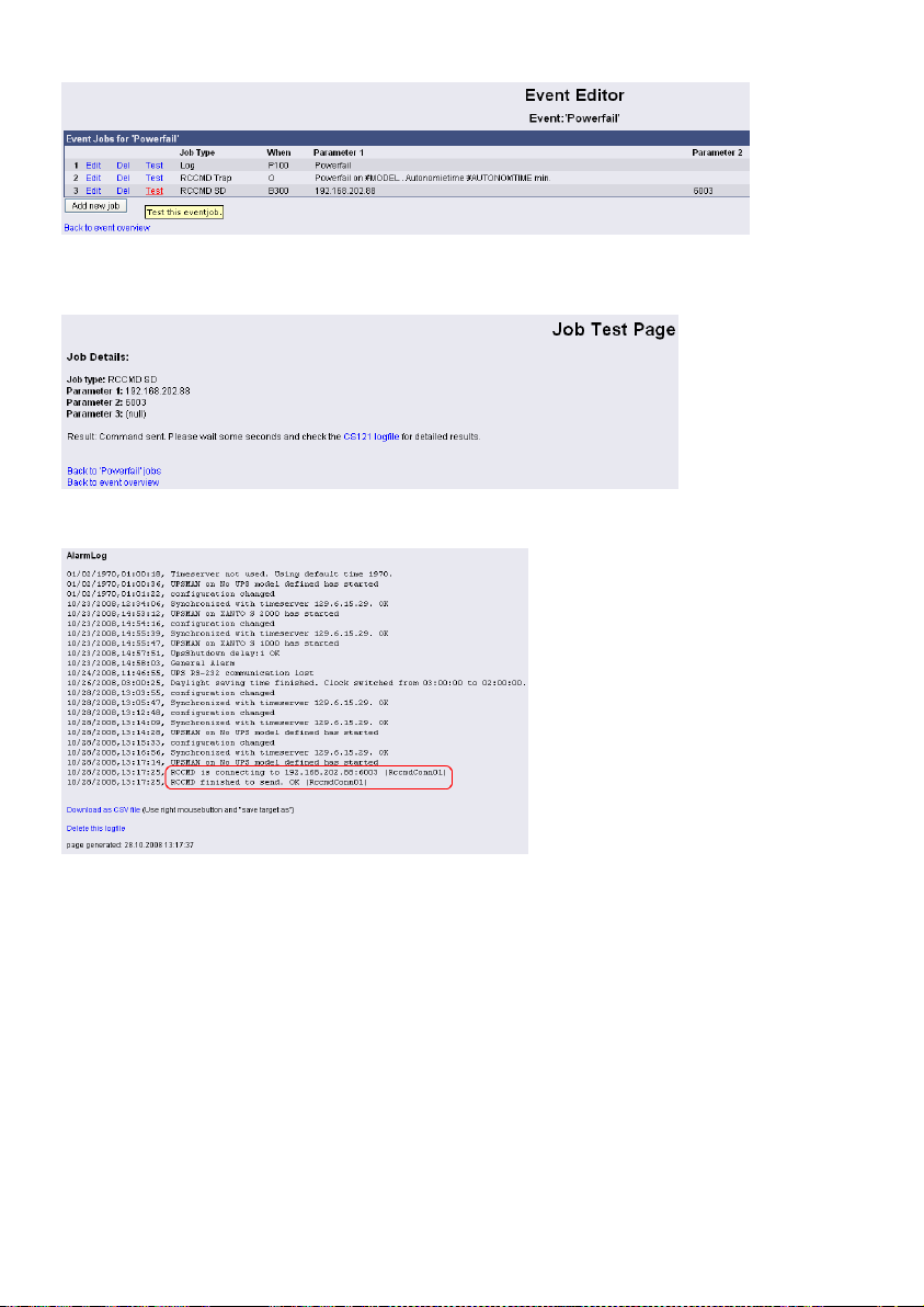
After you have clicked the “Test” button (Attention! The shutdown will be executed immediately
without consideration of the defined delay), the following message will be displayed:
You can see the successful sending of the signal into the “AlarmLog”:
4.4.5 Automatic Reset of the Redundancy Alarm
You can use the function „Send RCCMD cancel shutdown“, to discard a previously sent
shutdown automatically. If a shutdown was suppressed, because of the existing redundancy at
this point of time, but the problem was solved at the UPS intermediate, you can reset the
shutdown with the function „Send RCCMD cancel shutdown“. The client, which received the
shutdown, will be encouraged to reset it.
This command can be set individually into your CS121, UPSMAN or BACS WEBMANAGER
Events/Alarms configuration, but makes sense only, if the event, which will send the command,
is true, if the UPS is back in normal condition. For this the events „POWER RESTORED“,
„BATTERY LOW OFF“, „UPSMAN STARTED“ and „GENERAL ALARM OFF“ are suitable, if
they are provided from your UPS into the CS121. The job „Send RCCMD cancel shutdown“
would be set into these all-clear events, so that e. g. at restart of the UPS, the event „UPSMAN
STARTED“ would reset the accordant RCCMD client automatically.
Alternative: Should the job „Send RCCMD cancel shutdown“ not be present into your CS121,
UPSMAN or BACS WEBMANAGER, you can use the job „Send RCCMD shutdown to remote
client“ or rather „Send RCCMD execute to remote client“ alternatively.
Figure 61: HTTP – Event Editor / Test
Figure 62: HTTP – Job Test Page
Figure 63: HTTP – AlarmLog
60
Page 63
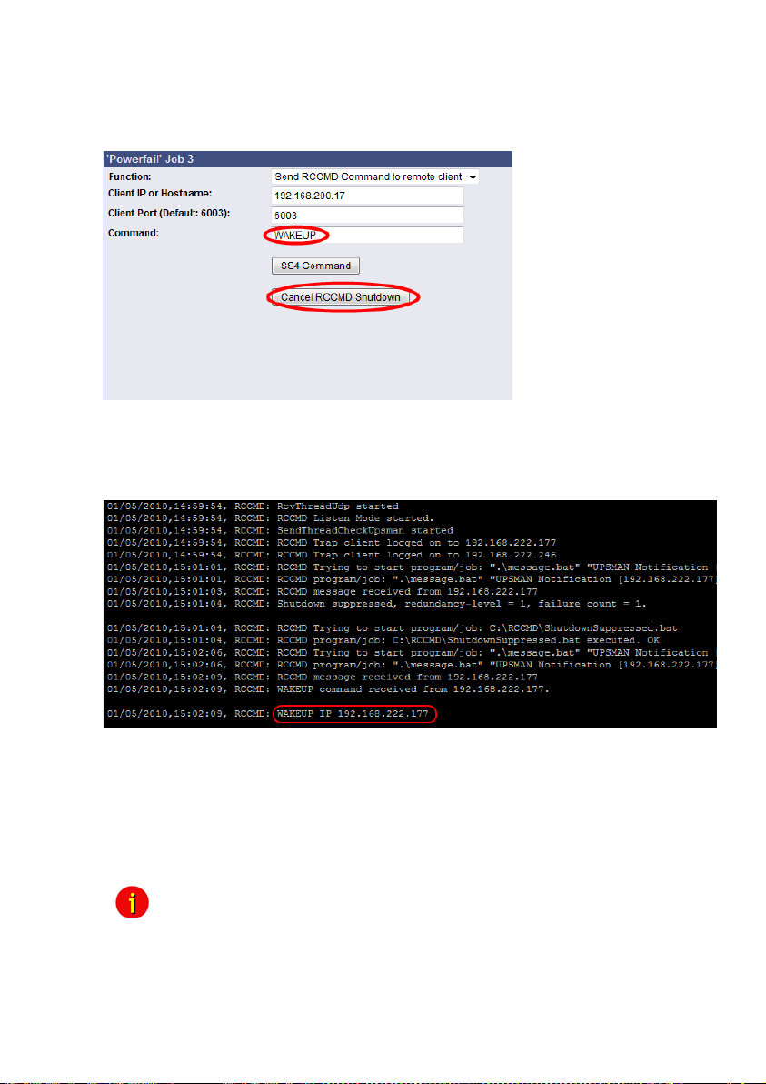
The parameter „WAKEUP“ got the same function like the „Send RCCMD cancel shutdown“
and resets the redundancy alarm of a RCCMD Client into initial state. For this the events
„POWER RESTORED“, „BATTERY LOW OFF“, „UPSMAN STARTED“ and „GENERAL
ALARM OFF“ are suitable too, to configure the function „Send RCCMD command to remote
client“ with the „WAKEUP“ command.
Figure 64: HTTP – Job Editor RCCMD WAKEUP
Click into the CS121 menu “Events/Alarms” onto “Power restored” and add a new job. Select
the function “Send RCCMD command to remote client”, set the accordant IP address of the
RCCMD client and click the “Cancel RCCMD Shutdown” button.
Figure 65: HTTP – Job Editor RCCMD WAKEUP
4.4.6 RCCMD Message
With this job the user can combine and configure a text message with RCCMD event. Text
messages can be sent to RCCMD receivers. This makes it possible to send text messages via
RCCMD (version 2 or higher) to a Windows 2000 server or a UNIX computer, using the “NET
SEND” or the respective “WALL” method. The problem with notifying network users on
different operating systems is therefore solved.
Note: The corresponding RCCMD clients must be running with RCCMD
version 2. RCCMD version 1 can only execute e.g. a shutdown as more
than one action are not supported by version 1. Please contact your
UPS dealer if you want to use these functions.
61
Page 64
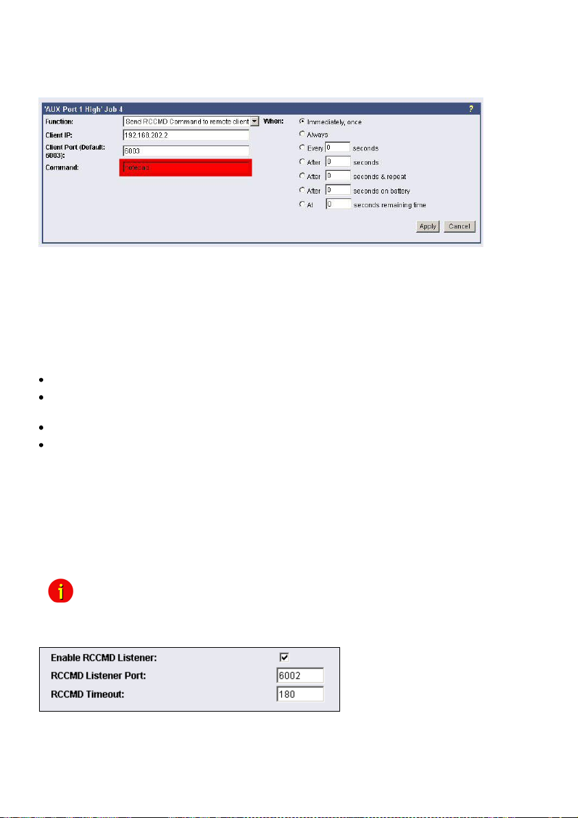
4.4.7 RCCMD Execute/Command
This RCCMD signal will cause any RCCMD receiver (e.g. another CS121, RCCMD client or
SITEMANAGER, SITESWITCH4) to execute a command or program.
Figure 66: HTTP - Job Editor: RCCMD execute/command
Any CS121, SITEMANAGER, SITESWITCH can also act as an RCCMD listener; see the
following examples:
Example of use 1: CS121-adapter as RCCMD-listener
If it is necessary to execute a command with parameters or a user defined script then these
commands must be prepared as an executable batch on the RCCMD client.
The following example toggles the state of AUX output port 2 to high. To ensure that the above
command works with a CS121 as RCCMD client the following four criteria must be met:
Enable RCCMD Listener and set RCCMD Listener Port in menu “Network & Security”.
Add IP of UPSMAN sender in the SNMP community of the CS121-RCCMD client (see also
section “SNMP”)
Target AUX port must be set to "use as Output" (menu AUX, see according section)
The send RCCMD Command must match the settings of the CS121 RCCMD listener client.
See the UPSMAN User Manual for setting up this job on a computer running UPS
Management Software.
Example of use 2: CS121-adapter switches an output
CS121 receives an external RCCMD signal to switch an output at the SS4 (Power Switch)
which is connected to the AUX of a CS121.
If you want to send from a CS121, UPSMAN, SITEMANAGER II, SITEMONITOR II,
SITESWITCH 4 or any other RCCMD sender a signal to any other RCCMD client e.g. to switch
at its AUX port an output, please follow the example below.
Note: To let the receiver act as RCCMD listener, same basic settings in menu
“Network & Security” are necessary: Please ensure that the option
“RCCMD Listener” is enabled and the RCCMD Listener port is specified.
(Usually the listener port is 6002)
Figure 67: HTTP – Enable RCCMD Listener
Generally there are 3 commands which can be transmitted from any RCCMD Sender:
62
Page 65
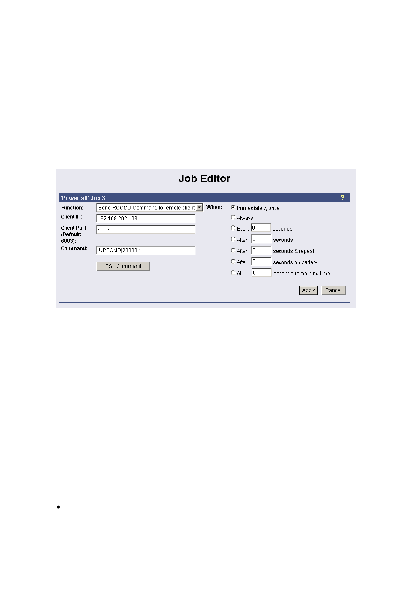
Switch Output (AUX): Syntax „|UPSCMD|20000|x,y“
where “x” is the port number from 1-8 (4 ports for CS121 AUX, SENSORMANAGER and
SITESWITCH and there are 8 ports for the SITEMANAGER)
y=1 => switch on
y=0 => switch off
“20000” is the command to switch outputs. (for other commands please contact GENEREX
support)
Syntax examples:
|UPSCMD|20000|1,1 = Output 1 on
|UPSCMD|20000|1,0 = Output 1 off
|UPSCMD|20000|2,1 = Output 2 on
|UPSCMD|20000|8,0 = Output 8 off
Figure 68: HTTP - Job Editor: RCCMD-Command
If you want to send a signal from a RCCMD client, e.g. UPSMAN or RCCMD Software, to
switch an AUX port of a CS121, do the following:
C:\RCCMD\
rccmd -se "EXECUTE |AUX|1|1" -a 192.168.202.165 -p 6002
ATTENTION! The blank after the “Execute” is important!
Common syntax for the switching of AUX ports:
|AUX|1|0 Port1, set to low
|AUX|1|1 Port1, set to high
|AUX|2|0 Port2, set to low
|AUX|2|1 Port2, set to high
|AUX|3|0 Port3, set to low
|AUX|3|1 Port3, set to high
|AUX|4|0 Port4, set to low
|AUX|4|1 Port4, set to high
Confirm a digital alarm : You can also use this syntax to e.g. confirm alarms for digital
inputs (e.g. Fire-alarm, door open, air-condition failed, etc.) which you see in the UNMS
software as “New Alarm”. E.g. if your UNMS software shows an active alarm and you want to
“acknowledge” this alarm by a switch witch you connected to a CS121 or SITEMANAGER,
than you can use the following syntax to program your device to send an “ACK” signal to the
receiver. After this your UNMS will show “Alarm acknowledged – recovery action in progress”.
63
Page 66
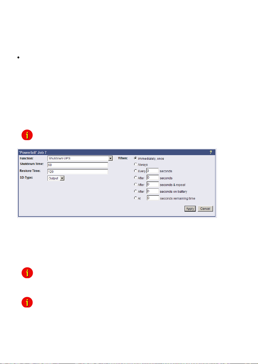
Syntax : |UPSCMD|20001|x
where x is the Portnr. (1-8). („20001“ is the ACK command for digital signals)
Syntax example: |UPSCMD|20001|2
This command confirms the Digital-Alarm 2 on a SITEMANAGER, SITEMONITOR,
SITESWITCH or CS121 AUX Inputs.
Confirm an analog alarm : The way it works with the ACK of analog alarms like
Temperature thresholds exceed on the UNMS.
Syntax : |UPSCMD|20002|x
where x is the Portnr. (1-8). („20002“ is the ACK command for for analog signals)
Syntax example: |UPSCMD|20001|4
This command confirms the Analog-Alarm 4 on a SITEMANAGER, SITEMONITOR,
SITESWITCH or CS121 AUX Inputs.
4.4.8 UPS shutdown
This event action enables an UPS shutdown. It is possible to configure when to send a
shutdown signal to the UPS in case of an e.g. battery low, fire alarm or if a complete power
down is wanted.
this function!
The example above configures that 60 seconds after the event powerfail has occurred, the
UPS is initiating a shutdown and the UPS waits another 120 seconds after the event powerfail
is gone (power restored), before the UPS start up is initiated.
4.4.9 Wake On LAN (WOL)
This function sends data packages to wake up other workstations into a local network. Use this
functions into the event “UPSMAN started”. You can also use the event “Power restored”.
password. Activate this function into the BIOS settings of the target workstation.
switch, the CS121 and the workstation are defined with “Autosensing”!
Attention: This command will cut off the power supply – only for UPS which support
Figure 69: HTTP - Job Editor: Shutdown UPS-Job
Note: Not all network cards are supporting this function. Some cards require a
Note: If you want to send WOL signals in different sub-networks, it’s required, that the
64
Page 67
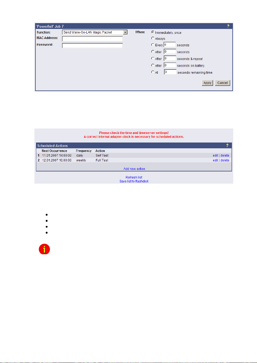
Figure 70: HTTP - Job Editor: Wake On LAN
4.4.10 Scheduled Actions
In this menu you can schedule actions for the CS121 like switch on/off UPS, execution of
battery tests, switch on/off bypass mode or the periodical sending of emails with attached log
files etc...
Figure 71: HTTP – Scheduled Actions
After you clicked the “Add new action” button, you can define new actions for the CS121. You
can select the following options for the execution of an action:
Once
Daily
Weekly
Monthly
Note: Please check the time and timeserver settings! A correct internal adapter clock
is necessary for scheduled actions!
4.4.11 CS121 for Transfer Switches
The CS121 is used from time to time for automatic transfer switches (ATS) too. The graphical
display depends on the manufacturer.
65
Page 68
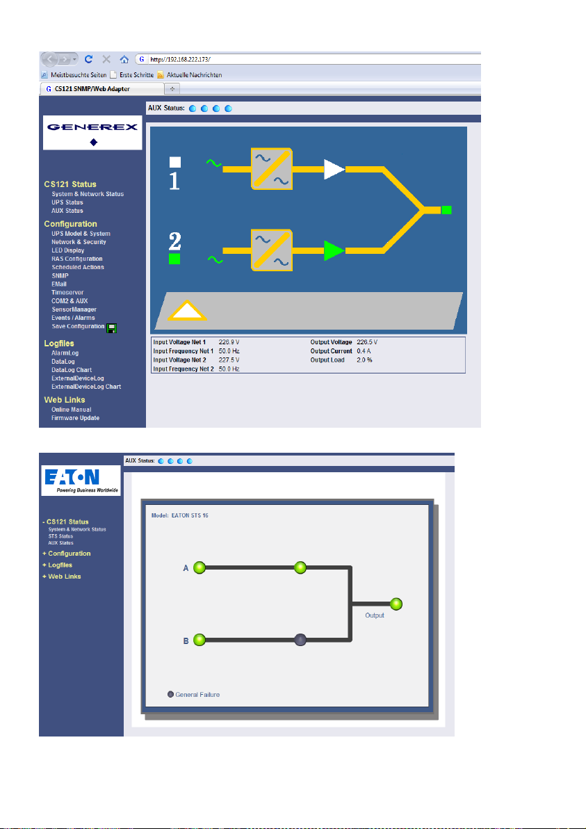
66
Figure 72: HTTP – Status Page Socomec Transfer Switch
Figure 73: HTTP – Status Page Eaton Transfer Switch
Page 69
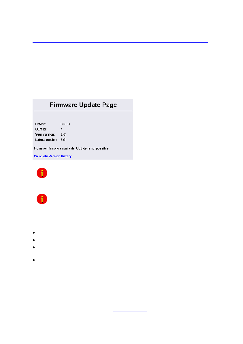
All ASYS, AEG and PILLER transfer switches are using the extended RFC1628 SNMP MIB
(Download). The models SOCOMEC STS and LTM got their own MIB (STS LTM MIB), which
is available as download from our website:
http://www.generex.de/index.php?option=com_content&task=view&id=63&Itemid=104
5. Adapter Software Updates (Firmware)
Usually the CS121-Adapter already contains a specified firmware-version and does not need
to be updated unless you have problems or you find a update recommendation on our website.
(use firmware online update link on CS121 page).
If you have connected your CS121 via LAN a link at the Webbrowser configuration page
(CS121 Firmware Update) indicates you with red or green coloured information whether you
should perform a Firmware-Update or not.
Figure 74: HTTP - Firmware Update Page
Note: We strongly recommend to update any firmware lower than 2.69 to the
actual version!
All actual Firmware-updates are provided at www.generex.de download page.
Note: Any interruption of a firmware upload may damage your adapter. If this is
the case, you have to reformat the adapter with special software See
section “Firmware Recovery”. or contact your UPS software support for
more information.
The boot procedure of the CS121-adapter performs several steps:
First, the firmware is going to be uncompressed.
Starting firmware
Control process called UPSMAN is going to be started and USV connection is trying to
established
Services e.g. Webserver etc. started
There are two ways to update your firmware-version, by using the Setup-tool or via FTP.
5.1 Firmwareupdate via Setup-tool
Firmware updates are available for free at www.generex.de. Download the specified version
(mind your OEM ID) and follow up the setup-procedure. If necessary, consult your UPS
dealer for further information.
5.2 Firmwareupdate via FTP
You can download the update file from www.generex.de or from your manufacturer site.
A firmware update via FTP does not change the operating system of the CS121 only. If you
want to change the manufacturer data, please contact your UPS dealer directly.
67
Page 70
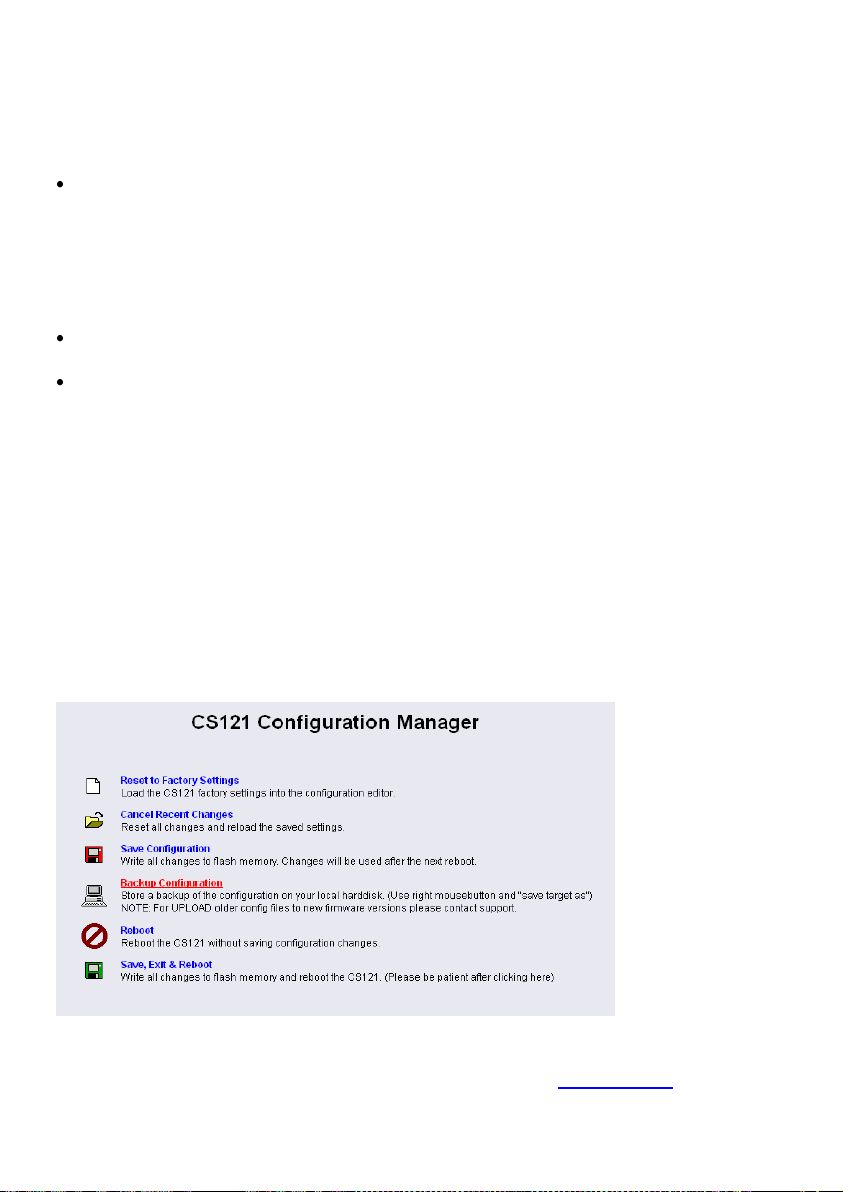
5.3 Firmware flash renewal and recovery
General information regarding the upgrading process of the CS121 - Known Problems
and Preliminary Precautions:
Any update will cause a deletion of all former settings. The adapter must be reconfigured
after the update. The current settings information can be saved by using an FTP connection to
your adapter to save the upsman.cfg file in the flash directory to a local directory. This file
contains all of the information about the current CS121 settings in a formatted text. Do not
copy this file back onto the adapter after the update as a replacement for the new upsman.cfg.
The information must be entered back into the settings using the adapters configuration
interface. Note that the http interface often contains newer settings options that are not yet
implemented in the telnet and terminal interfaces.
Any recovery should be made on the default IP Address 10.10.10.10. Put DIP Switch 1 and
2 in the OFF position before starting.
Please avoid the use of routers and switches between your computer and the CS121, if
available use Hub (recommended) or a direct line (Ethernet-cross-cable).
Instructions for recovery procedure:
In case the CS121 is not running, has any defect or other problem, please put dip switch 1 to
OFF (Dip 2 should be always OFF) and follow the procedure below:
1. Before starting the update, unplug the adapter from the power supply (slot cards have to be
removed from the slot).
2. Set a route to default IP-Address. Command syntax on your windows computer: "route add
10.10.10.10 <your IP address>". Also note that the flash tool can also be used to set the route
for you by checking the set route check box in the update interface.
5.4 How to get the “upsman.cfg” from a CS121 to your computer via FTP
Click on the web-interface of your CS121 into the configuration menu bar the „Save
Configuration“ button. Click the „Backup Configuration“ icon with the right mouse button, select
„Save Target As“ and choose the path of your hard disk, where you want to store the
„upsman.cfg“ data.
Figure 75: CS121-Configuration Manager
Via FTP: Enter the following into the address field of a web-browser: ftp://<ip-address of your
CS121>. Enter the username admin and the password cs121-snmp. You will find the
„upsman.cfg“ into the „flash“ folder.
68
Page 71
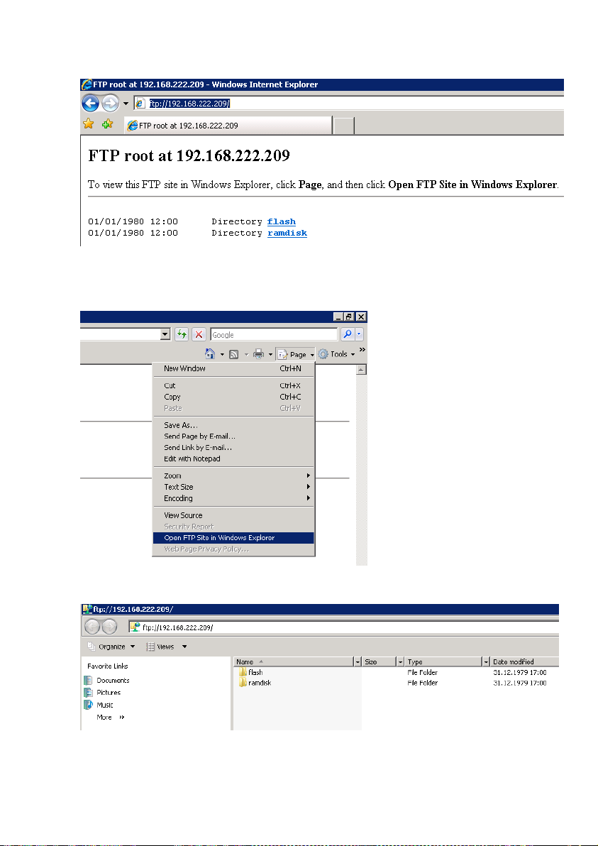
Figure 76: CS121-FTP Access
Figure 77: CS121-FTP Context Menu
Figure 78: CS121-FTP Folders
69
Page 72
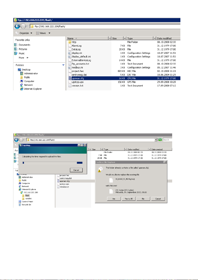
Figure 79: CS121-FTP Upsman.cfg
After you have updated your CS121, please open the „new“ and the stored „upsman.cfg“ in an
editor. Now check, if the parameter of the new data are present into the stored data. If not, you
need to copy the missing parameter of the new data into the stored „upsman.cfg“.
Now you can overwrite the „upsman.cfg“ into the „flash“ folder via ftp.
Figure 80: CS121-FTP File Replacement
Just reboot (do not select „Save, Exit & Reboot“) the CS121 via web-browser.
70
Page 73
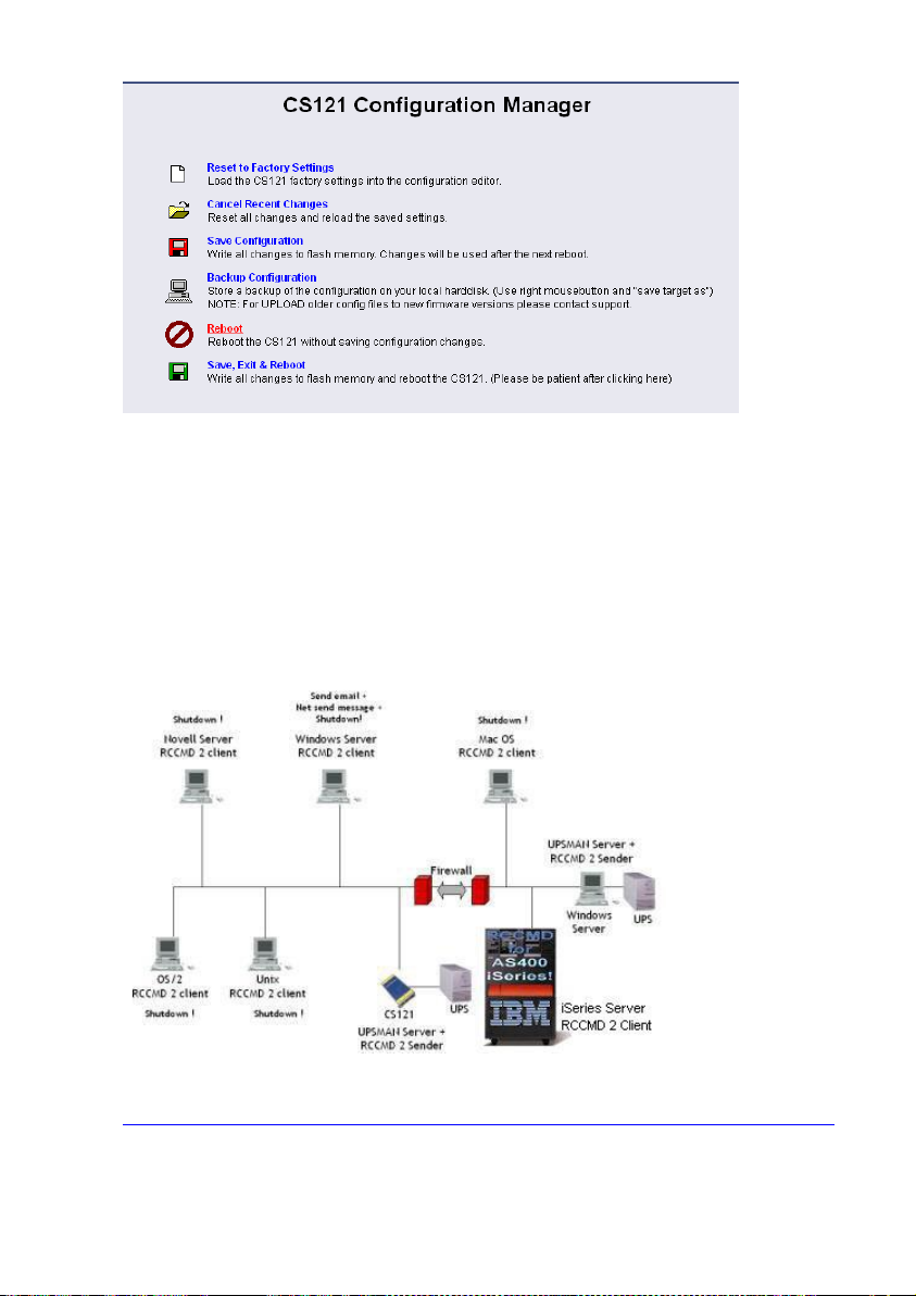
Figure 81: CS121-Reboot
At the reboot, the stored „upsman.cfg“ will be load and the CS121 will obtain the configuration
prior of the update.
6. Additional Software
6.1 RCCMD
RCCMD is the client module for integrating an unlimited number of computers of any operating
system into an UPSMAN managed UPS facility. The main purpose is to transmit shutdown
signal or messages to RCCMD clients in other networks or on other OS.
Figure 82: RCCMD - Overview
The RCCMD Software got his own user manual. Please follow this link to get it:
http://www.generex.de/generex/download/manuals/manual_RCCMD_Win_Unix_Mac_en.pdf
6.1.1 RCCMD with SSL for Windows
The Secure Sockets Layer (SSL) protocol is a cryptographic protocol that provides security
and data integrity for communications over TCP/IP networks.
71
Page 74
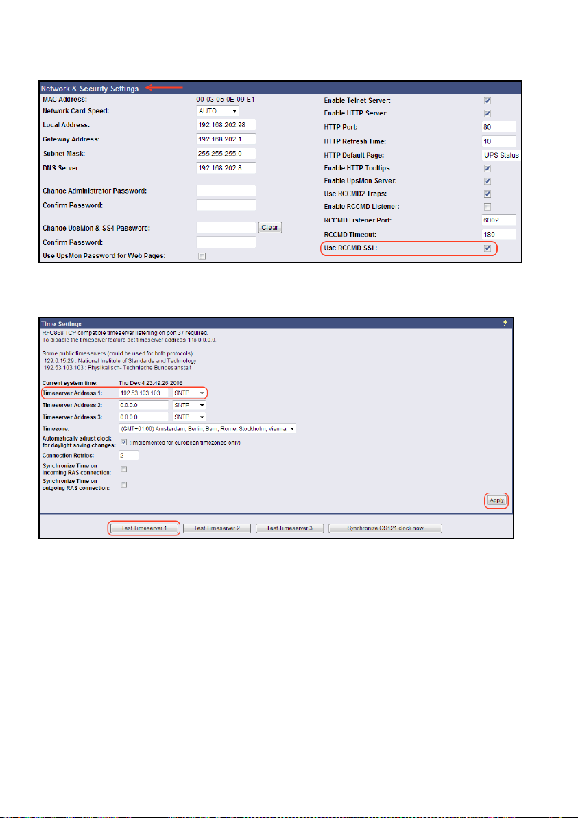
Use your Web-browser to navigate to the address of your UPS Web-Manager. Click the
“Network & Security” configuration button and enable the SSL network feature.
Figure 83: RCCMD SSL Settings
The SSL network feature requires correct time settings, so it is required to configure a
timeserver. Click the „Timeserver“ configuration button and enter the address of at least one
timeserver.
Figure 84: Timeserver Settings
Click the „Save Configuration“ button and the „Save, Exit & Reboot“ button to confirm your
settings.
72
Page 75
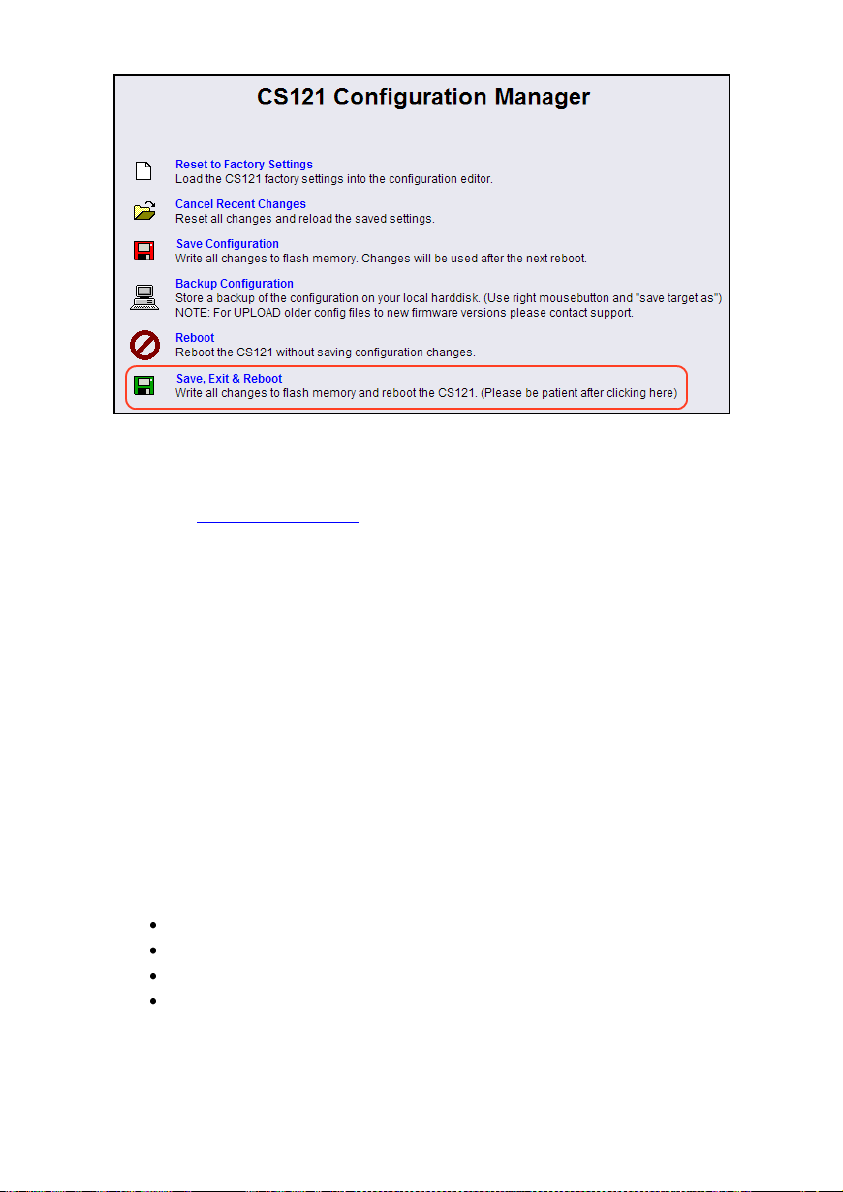
Figure 85: Settings Confirmation
6.1.2 RCCMD with own SSL certificates
In this chapter we will describe, how to use an own SSL certificate with RCCMD, e. g.
OpenSSL ( http://www.openssl.org ):
Be your own CA
Using OpenSSL it is quite simple to become your own CA. Just run:
CA.pl –newca
Done! Just ensure, that you select a useful CN (common name)!
Create your RCCMD certificate
You need to create your certificate for RCCMD now. As it will use it for verification, it should
contain the same useful common name (CN), that you selected for the CA. The private key
must not be encrypted to let the RCCMD Client (service) start without trouble. Therefore we
use the “–nodes” option and the “-newreq” command:
CA.pl –newreq -nodes
Sign with your CA:
CA.pl –sign
Now create an empty file named “rccmd.pem“ and copy the cert information of newcert.pem
(rccmd certificate), newkey.pem (private key) and cacert.pem (CA) into it. Please note, that the
exact copying is required to use it without trouble!
Use your own RCCMD certificate
Do the following steps at the RCCMD Client and every sender (e. g. UPS Web Manager):
Backup the existing “rccmd.pem”
Replace the existing “rccmd.pem” with your own
Restart the RCCMD Client
Restart the RCCMD Sender
6.1.3 RCCMD client as relay station
In order to reach a bigger number of RCCMD receivers, the adapter needs to be operated as
relay station. The receiver will be configured so that it will receive a RCCMD signal and this
signal is then used to start a batch file, which then starts even more RCCMD sender signals.
73
Page 76
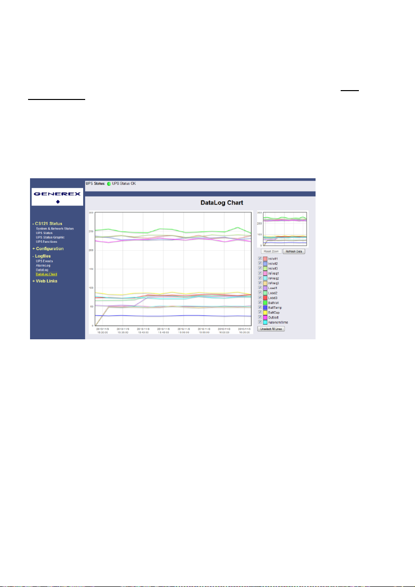
Please take a look into the RCCMD Software usr manual for further information.
6.1.4 License regulations
Please note that in order to use these functions legally, the corresponding RCCMD program is
installed and started from the UPS-Management Software CD resp. see www.generex.dedownload page for the latest version. (see above) The license code can only be used once
per installation. If more computers need to be added to the shutdown process, additional
licenses are required. The CS121 package does usually contain a single license for RCCMD to
shutdown 1 computer. For more computers to shutdown you have to order separate RCCMD
client licenses. If you want to shut down more than 50 clients in one company or organisation,
please contact your UPS dealer and order an enterprise license. Then you will get one
RCCMD license for all clients only.
6.2 jChart
jChart is a GENEREX Web 2.0 Control Chart for all web-browsers, which simple visualizes the
data log file of the CS121 (since CS121 firmware version 4.27).
Position the mouse cursor accordingly, if you want to identify an additional coloured line of a
desired point in time. If a timeserver was defined, the data prior of 2000 will be filtered
automatically.
74
Figure 86: jChart Display of the CS121 Data Log
Page 77
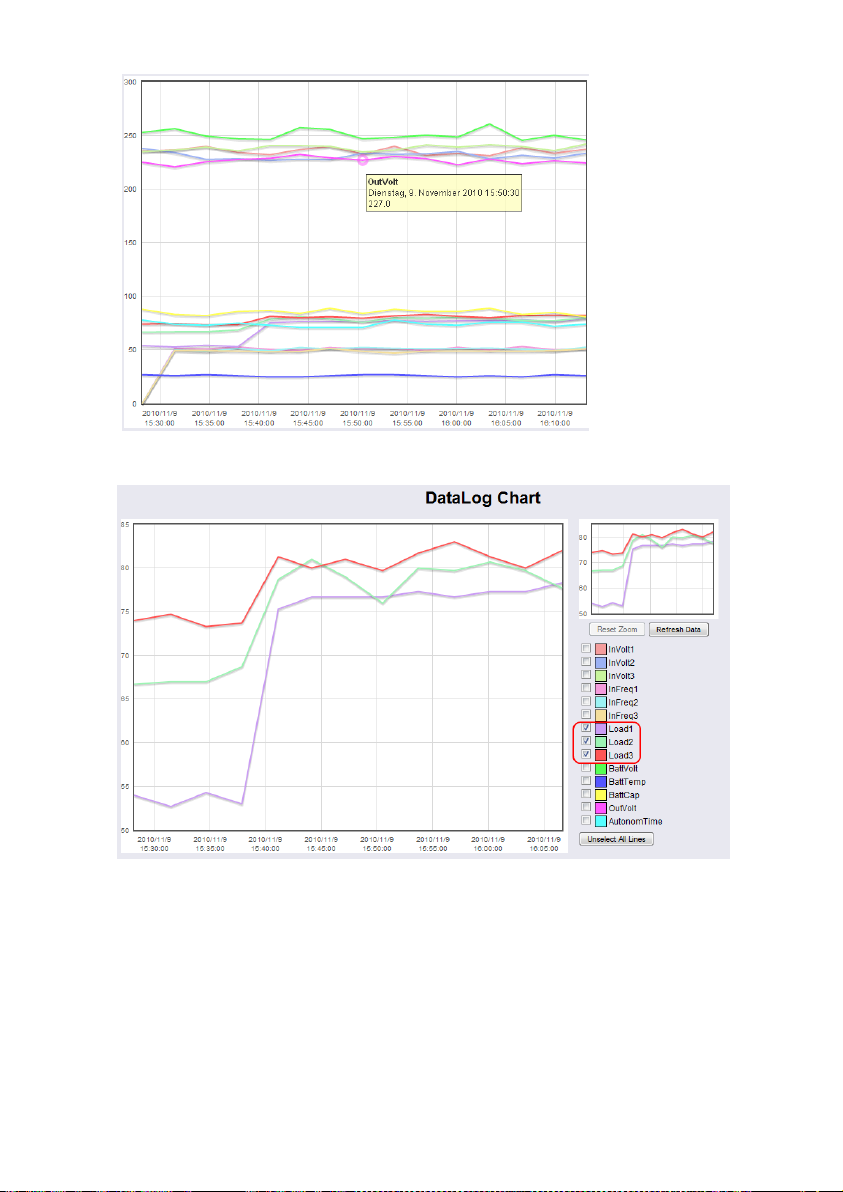
To display the desired values into the chart only, click the “Unselect All Lines” button and
check the accordant variables.
To increase a desired area, click the left mouse button into the area and drag an accordant
rectangle from the upper left side to the lower right side.
Figure 87: jChart Display of a Measurement Value
Figure 88: jChart Display of the Loads
75
Page 78
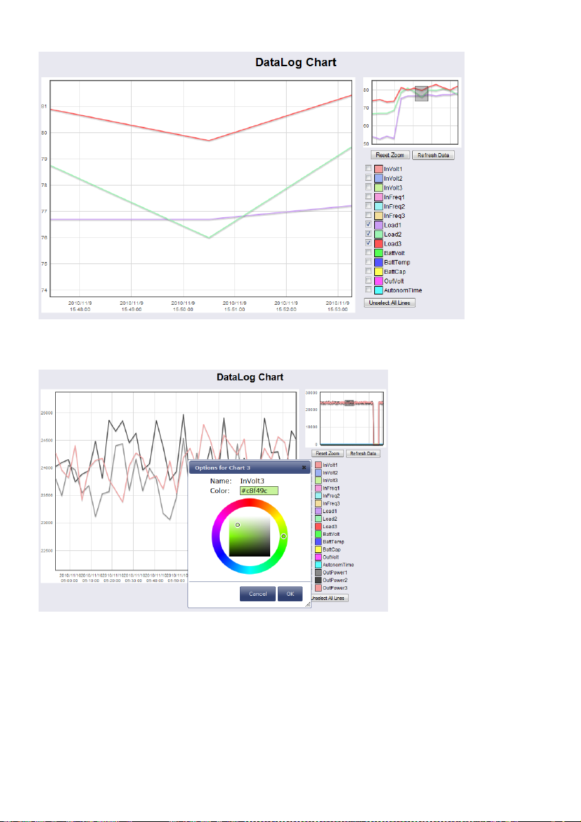
Click the “Reset Zoom” button, if you want to get back to the initial state. If you want to change
the colours for the values, click the coloured box prior of the variable.
6.3 gChart
gChart is a GENEREX plug-in for the MS Internet Explorer available as a free download from
the GENEREX web site. Quickly and easily visualise all of the CS121-adapter logfiles using
Generex's ActiveX graphical log controller GChart when using the Internet Explorer. Discover
UPS problems more easily and optimise system tuning more rapidly. Navigate through the
data with the mouse using functions like zoom and pan with continuous motion in real time and
query interpolated data values by clicking in the areas of interest. Customize the view by
moving or toggling off the legend, toggle off and on the data grid and also switch individual log
values on and off.
Figure 89: jChart – Zoom-In of an Area
Figure 90: jChart – Colour Selection
76
Page 79
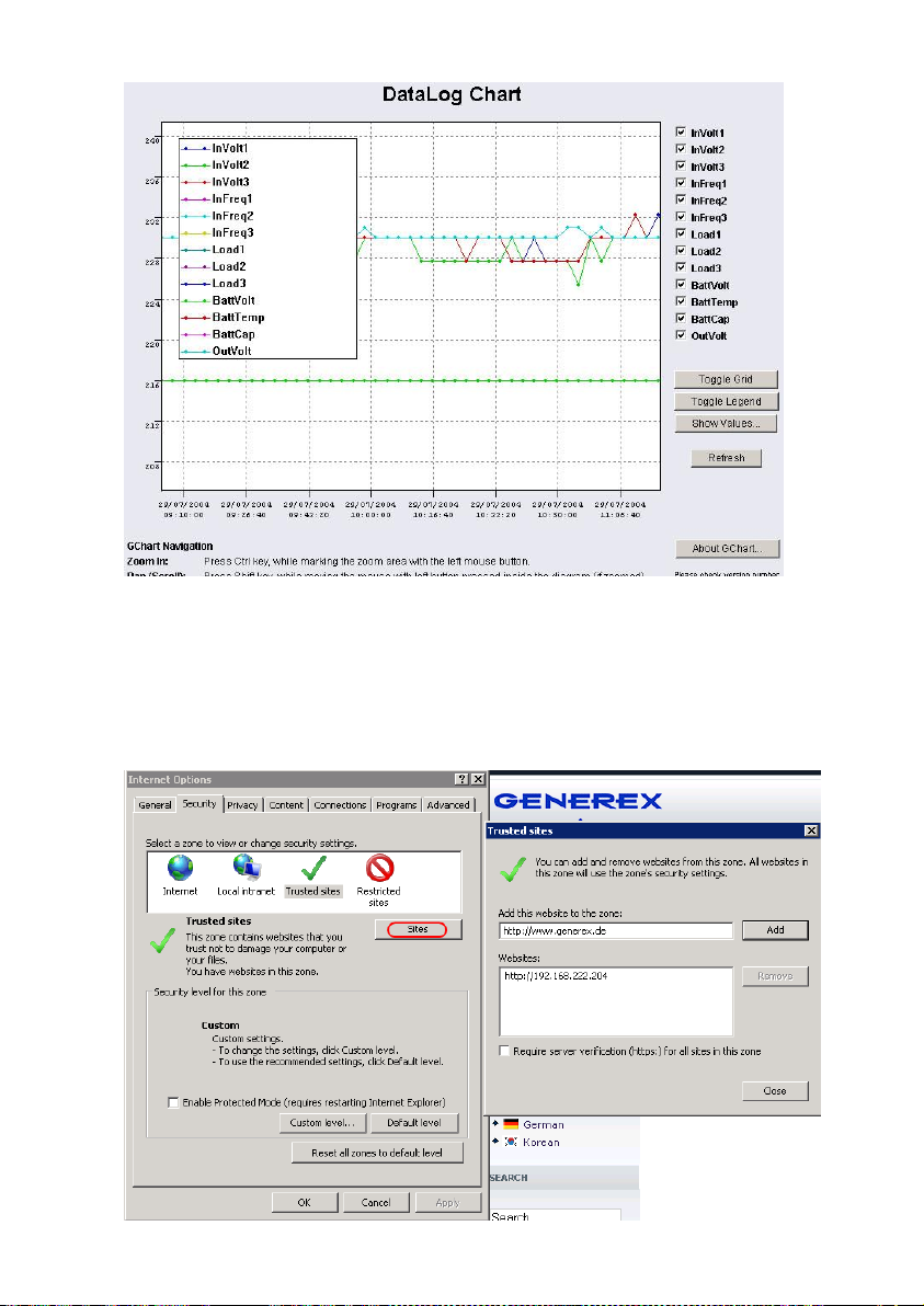
Figure 91: gchart plug-in for the internet explorer
Get the gChart experience now by visiting our online CS121 at: http://q01.generex.de/ and be
sure to follow the GChart logfile links.
In order to activate this function, the following adjustments in the Internet Explorer Options are
required:
Click via the menu „Tools“ into the Internet Options.
Select the tab „Security“.
Click the „Trusted Sites“ icon, than the „Sites“ button and add the desired IP address.
Figure 92: Internet Options of the internet explorer
77
Page 80
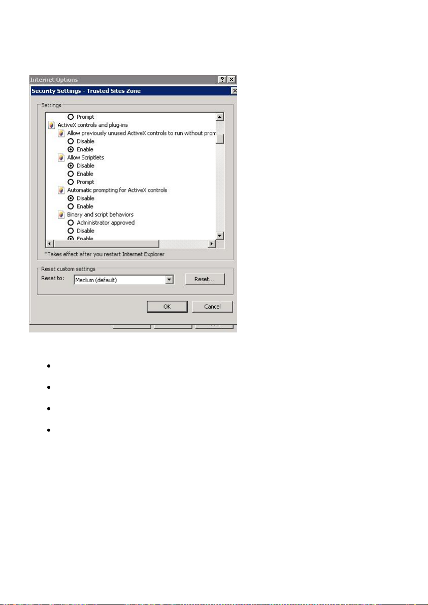
Close the opened windows via „Close“ and „Ok“.
Click into the Internet Options and Security again. Click via „Custom level...“ into the Security
Settings of the Trusted Sites Zone.
Figure 93: Security Settings
Activate the following options:
Allow previously unused ActiveX controls to run without prompt
Download unsigned ActiveX controls
Initialize and script ActiveX controls not marked as save for scripting
Run ActiveX controls and plug-ins
Close the opened windows via „Ok“ and restart your Internet Explorer with the desired site.
6.4 UPS monitor (UPSMON)
UPS-Monitor (UPSMON) is the graphical monitoring and command inferface application for
UPSMAN and is available in standard and custom interfaces.
In order to display the UPSMAN provided data via the network customer friendly, the modules
UPSMON and JAVAMON are delivered for free. The UPSMON is a client for all Microsoftplatforms, whereas the JAVAMON can be started on all operating systems, that support JAVA.
A LAN, WAN, or the Internet (TCP/IP) connection can be used as a connecting network
between UPSMAN and the management interfaces. Both graphic interfaces can be
customised to the demands of the UPS manufacturer, that’s why the UPSMON appearance
differs for almost every UPS maker product. This allows for an adaptation of all UPS systems
78
Page 81
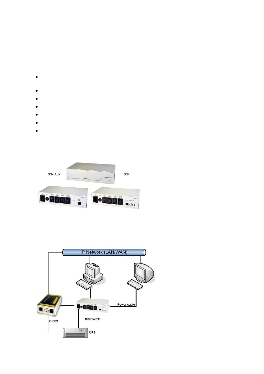
with all different kinds of functions. UPS systems, with serial interfaces often incorporate of a
variety of measured values and status information. Those can be displayed using overview or
block diagrams. Other devices, such as diesel generators or extra measuring units can be
integrated with this management software via the network. A separate password protected
screen can be created, if the devices also support remote controlling commands. The values
and status information, which are stored in the UPSMAN log file, can be requested from every
computer with an installed UPS monitor module.
Features:
Monitoring of all UPS systems that are connected in the network via UPSMAN and
respective SNMP adapter
gCHART dynamic visual log file graphic tool
Remote controlling of all UPS systems via the network
Graphic display of the UPS input data (voltage, power)
Read out and display of the UPSMAN event-log files
Programming of the UPSMAN scheduler
Graphic screens containing all UPS information also under UNIX, MAC (JAVAMON)
7. CS121-Enhancements, Field of applications
7.1 SiteSwitch4 (SS4) and SiteSwitch4AUX (SS4AUX)
Figure 94: SideSwitch4 and SS4 AUX
SITEWITCH4AUX is a high-performed extension of the CS121-adapter but can also be
operated as stand-alone solution with the possibility to connect to UPS or UPS-similar devices.
The SITESWITCH has 4 power outputs sockets, which can be configurated by the event
settings of the CS121 or any other RCCMD compliant sender like SITEMANAGER,
SITEMONITOR.
Figure 95: CS121-Installation with SideSwitch4
79
Page 82
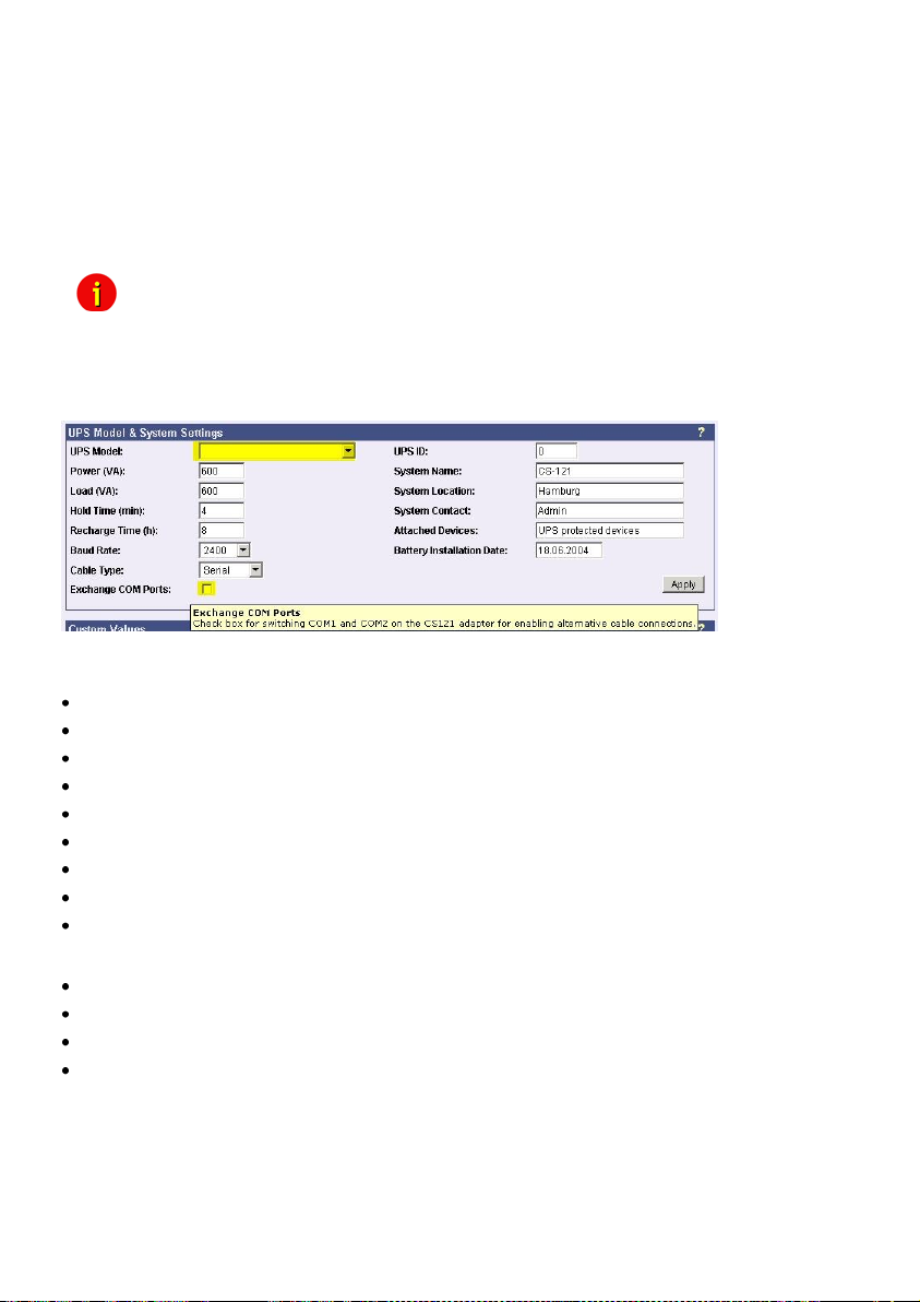
Using the integrated Webserver, the SITESWITCH 4 enables the monitoring and the remote
control of its 4 power outputs. The power sockets can be switched on and off individually. This
can be done either manually via the HTML browser interface or UPSMON or automatically
using the EVENT manager of the CS121 - or any other network CS121 or compatible device.
When executing the action using the EVENT manager of the CS121, the power switching can
be preconfigured to run with delays or to run on a schedule. Both the UPSMON time scheduler
and the HTML time scheduler can be used to configure a power switching time schedule.
This task can also be achieved using the full version of the UNMS UPS Network Management
Software.
Note: (only SS4, not SS4AUX) If you wish to use a UPS with your SS4 then
Figure 96: Exchange COM Ports 1 & 2 for SS4
7.1.1 SS4 Feature overview
4 configurable powers sockets with a breaking capacity of 230V/8A
Power socket status indicator via HTML, UPSMON, UNMS or SNMP
Control via the internal CS121 or via remote CS121 or RCCMD compatible devices
Remote control of the powers sockets via HTML Browser (Password protected)
LED-Status of the power sockets
Small metal casing with 1.5RU, designed for 19"-Rack Mountings (mounting frame included)
High breaking capacity (8A), input with IEC 16A.
Programmable power switching via the HTML and UPSMON Scheduler
Delay of alarm (e.g. UPS alarms) triggered power switching on COM1 of the CS121
7.1.2 SS4 Contents
SITESWITCH 4
16A IEC 230V power cable
2 mounting irons for 19“-Rack installation
manual for SS4
The manuals are being constantly updated and therefore the reader is encouraged to check
our website for a newer download version of the adapter manual. Check
http://www.generex.de for manual updates.
7.1.3 SS4 Installation
The power consuming devices are connected to the SS4 using IEC 250 VAC/6A plug cables.
The SS4 has 4 IEC 250VAC/6A chassis sockets that can be switched on and off separately.
you must install the appropriate CS121 Firmware on your SS4. The
default Firmware on SS4 (OEMID 27) is for the usage without UPS, as
standalone remote powerswitch. For UPS usage at the SS4 you must
also be sure to set the Exchange COM Ports checkbox and then use the
configuration cable (not included) to connect the SS4 with your UPS.
80
Page 83

Special notice is to be given to the 8A threshold breaking capacity; exceeding this limit will
cause the SS4 fuse to break leaving all connected devices without electricity.
Note: Due to errors that may cause the switched off power outlet to remain on
Use the provided mounting irons to fix the SS4 into a 19“ rack. Place the SS4 so that the front
panel of the SS4 can be securely screwed onto the 19“ rack housing while insuring also that
the power cables can be connected from behind as well.
As soon as all of the power consuming devices are connected to the SS4, the IEC 16 power
supply cable can be connected. Upon establishing power to the SS4, the green „POWER„ LED
will light up, and the 4 „Power Socket Status LED“ one for each of the sockets should be unlit.
This means that none of the sockets are being provided with power thus cutting the connected
devices from the power supply.
The CS121 establishes a user interface for the SS4 for which the user has the option of using
either UPSMON, Webbrowser, UNMS or an SNMP-Program. All communications take place
either through a modem or network connection. Detailed information is covered in section 7.7.9
AUX and SS4 Settings.
7.1.4 SS4 - Technical data
Inputvoltage: 230V AC +/- 5%
Max. Power Input: 16A
Max. Power Output per socket: 8A (Load at cos phi 1)
Dimensions 260x180x60mm (BxTxH), with 19” : 1,5U
Operating temperature: 0-40°C/rel.Humidity0-95% non condensating
7.2 Sensor SM_T_COM
The SM_T_COM is a temperature sensor for the use with a GENEREX CS121. It has a range
from -25° - 100° Celsisus (-13° –212° Fahrenheit) and comes with a 1.8 meter cable for
connecting to the CS121 COM2 port. The SM_T_COM is designed for monitoring and
management of 19"- racks, UPS rooms, server and data center rooms and for industrial
applications. Simple Plug' n Play connections insure that the sensor can be easily and safely
installed.
it is necessary to conduct the following: Before connecting any power
consuming devices with the SITESWITCH 4 or working on any power
consuming devices already connected to the SITESWTICH 4, make sure
that the SITESWITCH 4 is not connected to the power supply by pulling
its power cable out of the power socket.
Figure 97: The Sensor SM_T_COM
81
Page 84
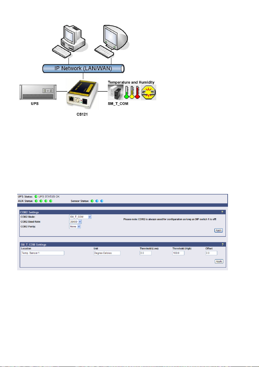
Figure 98: CS121-Installation with temperature SM_T_COM
The SM_T_COM (also available as SM_T_H – a combination of Temperature and Humidity) is
a temperature sensor with an RS232 protocol which can be connected directly to the CS121
COM2 port. (Not BUDGET series).
The SM_T_COM shows the actual values on the CS121 Webserver screen and allows to
trigger alarms, emails, messages in case the values exceed configurable thresholds.
SM_T_COM is simply connected with the original CS121-TEMP cable (part of every CS121
SC and L) to the COM2. In the Webinterface COM2 & AUX you have to change to the COM2
mode to “SM_T_COM”, press “apply” and “save&exit” and reboot to start the CS121 with your
new settings. The Configuration of thresholds and Events is made via the Event-configuration
windows and the SM_T_COM configuration page.
7.2.1 SM_T_COM configuration
Figure 99: CS121- SM_T_COM Settings
Enter the desired values for the Threshold (low) and Treshold (high).
You can calibrate every sensor with the Offset, that means if you want to rise a measured
value for 5°C, just modify the default range from 0.0 to 5.0. Therefore you are able to adjust
the measurement values like a gauged thermometer.
You can define the following functions for SM_T_COM Events (see figure below).
82
Page 85
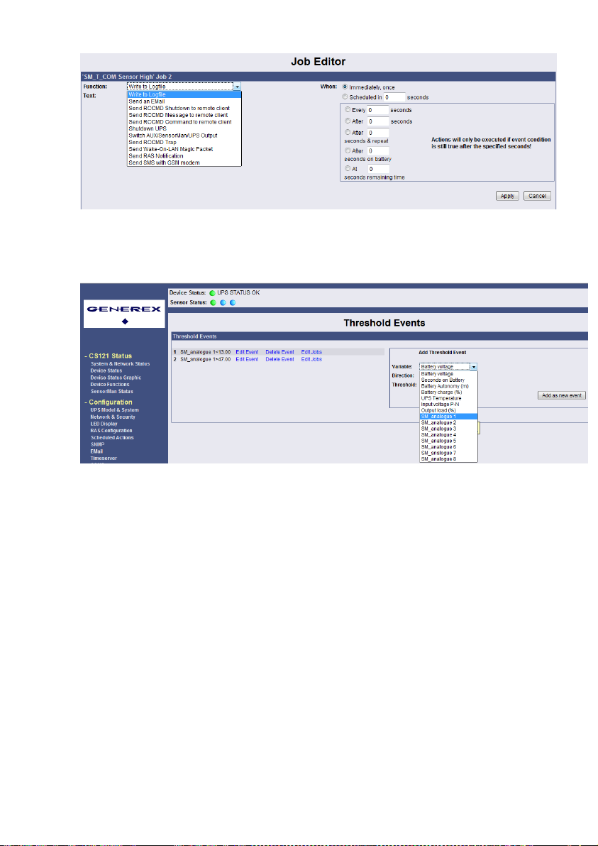
Figure 100: CS121- SM_T_COM Functions
The CS121 firmware version 4.26.x provides the option to define threshold events for the
analogue inputs. Click the “Configure Threshold Events” button into the CS121
“Events/Alarms” menu.
Figure 101: CS121-Configuration Threshold Events of analogue Inputs
In this example, a below threshold of 13 was defined for SM_analogue 1, in this case for the
temperature in °C, which will appear into the Event Configuration, after you executed the
“Save, Exit & Reboot” function.
83
Page 86
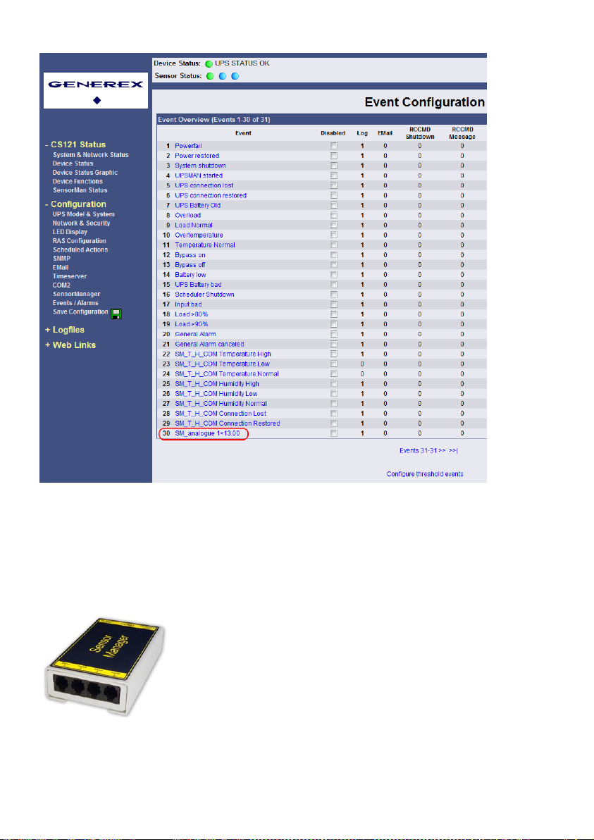
Figure 102: CS121-Configuration Threshold Event for SM_analogue 1
7.3 SENSORMANAGER & SENSORMANAGER II
7.3.1 General information
If more than 1 or 2 environmental values are wanted to manage, than the SENSORMANGER
(SensorMan) is your choice. This device is a data measurement and collecting unit which
allows the individual measurement and monitoring of 8 analog measurement devices (0-10V)
and 4 digital alarm inputs or 4 outputs (open collectors).
Figure 103: Sensor Manager (SensorMan)
The SENSORMANAGER is a system extension for the CS121 Professional, BACS
WEBMANAGER, CS121 Mini und CS121_R_II.Universal Remote Sensor Control Box for the
monitoring of temperature, humidity and many other types of sensors as well as for the the
management of digital input/output signals. 8 analog inputs (0-10V), + 4 digital input and/or
outputs (48 V 500mA). Digital Outputs are configurable as normally open or as normally
84
Page 87
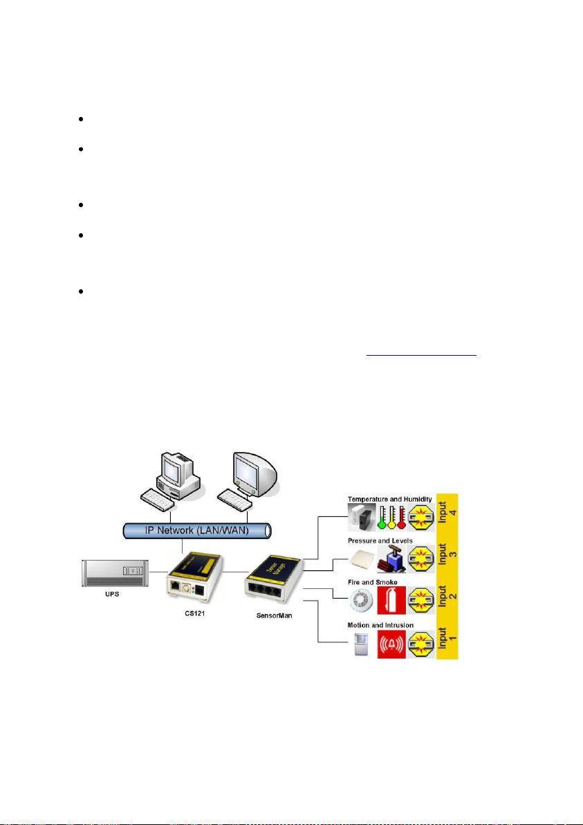
closed. Digital input connections directly through sensor for some models or connect directly to
the RJ11 socket. Convenient splitting plug available for attaching two sensors to one RJ11
socket.
Purpose:
Monitoring of temperatures, humidity and other analog data in computer rooms with
automated response to system alarms.
Alarms can be individually configured and defined for trip contacts such as fire, smoke and
intrusion, and minimum/maximum thresholds values can be set for analog devices such as
humidity, temperature and pressure, fluid level, etc. – any sensor which transmits its values
between 0- 10 V may be connected to a SENSORMANAGER.
Data logging, logging of alarms, automatic shutdowns of network computers, and other
actions can be set as reactions to critical alarms.
All system operating and configuring can be done remotely via Web browser. The EVENT
driven alarm management system of the CS121 informs the administrator of problems and
may automatically switch off computers and other devices (Optional extensions: SITESWITCH
4 or SITEMANGER).
The SENSORMANAGER is an extension to the CS121 Webmanager. If you want to connect
any other computing device, please download the RS-232 protocol for the SENSOR
MANAGER from our website and adjust your software to this communication type.
Important:
New firmware for your CS121 is available for download at: http://www.generex.de
7.3.2 Installation and Network integration
Figure 104: CS121-Installation with SENSORMANAGER
As shown in the figure above CS121 can also be applied to observe and react on alarms of the
SENSORMANAGER-Inputs. Therefore, the CS121 COM2 port is connected and configurated
for the SensorManager’s AUX- and Sensor-Input/Outputs. Within the CS121 configuration it is
possible to define actions, which will be released from events of the SensorManager’s devices.
Connecting the SENSORMANAGER Box
The SENSORMANAGER has to be connected with the original configuration cable (not
included) of the CS121 to COM 2.
85
Page 88
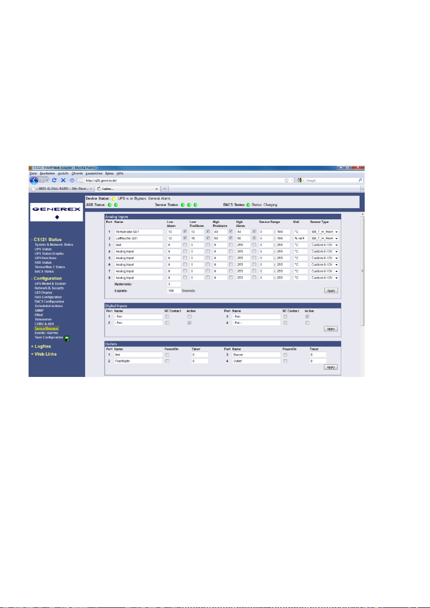
The sensors for the SENSORMANAGER may be connected direct to the socket Inputs 1-4
using an RJ12 cable. In this configuration you can only use up to 4 sensors. If you want to use
all 8 analog inputs, you have to use a splitting plug (optional) or connect the sensors directly to
the Channel Inputs as described above.
If you use the sensor type SM, you may connect a second SM sensor to the input of the first
SM. You can not connect more than 2 SM sensors in line.
For connecting an alarm contact to the SM sensor, you may use the first or the second SM
contact input/output, but not both. Only one digital input/output is available per socket.
OTHER SENSORS: If you use other sensors than SM, EE or TM, you must use a splitting plug
in order to connect more than one sensor to a single INPUT of the SENSORMANAGER.
For setting up the sensors in the SENSORMANAGER make sure your configuration matches
your sensor type, e. g. see example:
Figure 105: SENSORMANAGER II Settings
Using the splitting plugs (order number SPSMRJ) it is possible to connect up to 8 sensors and
4 contacts to the SENSOR- MANAGER. A MOUNTING KIT (sold separately) is available for
affixing the SENSORMANAGER to walls and railings.
The power supply for the SENSORMANAGER may also supply an external CS121 using a
SM-CS121 type cable (sold separately) by simply connecting the POWER OUT of the
SENSORMANAGER with the POWER IN of the CS121 external.
Startup the SENSORMANAGER
Connect the sensors to the SENSORMANAGER. Connect the SENSORMANAGER using the
Mini8-DBSub9 cable to the COM 2 port of the CS121. Finally, plug the power supply into one
of the UPS power outlets. Check the LEDs on the bottom of the SENSORMANAGER; the right
one should be flashing (reading request from CS121 COM2) and the left one should be
constantly lit (power supply on). The flashing LED shows the requests from the CS121, the
other LED shows that the device has started.
86
Page 89
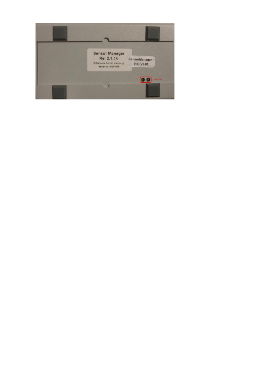
Figure 106: SENSORMANAGER II LEDs
Note: You have to configure the CS121 COM2 port to “SensorMan” (for SENSORMANAGER II
“SensorMan 2”) – otherwise the CS121 will not start making requests to the SENSOR
MANAGER.
See the CS121 user manual for instructions on how to configure the CS121 for operation with
the TEMPMAN/SENSOR MANAGER and how to manage and set the alarms.
The latest version of CS121 user manual is available for download at:
http://www.generex.de/wwwfiles/dokus/1/cs121/german/pdf/cs121.pdf
When the SENSOR MANAGER is running, you will see the values in the AUX section of the
CS121 Web browser.
Detection of the analog temperature values via variables:
#TEMP1
#TEMP2
#TEMP3
#TEMP4
#TEMP5
#TEMP6
#TEMP7
#TEMP8
Pin layout of INPUT Socket the SENSORMANAGER Box:
INPUT 1:
Pin 1 Voltage 9-24Volt +
Pin 2 Analog Channel 1 (0-10V+)
Pin 3 Analog Channel 5 (0-10V+)
Pin 4 Ground
Pin 5 OUTPUT: Open collector OUT 9-24 V, max. 30mA
Pin 6 INPUT: Digital Input 9-24V
INPUT 2:
Pin 1 Voltage 9-24Volt +
Pin 2 Analog Channel 2 (0-10V+)
Pin 3 Analog Channel 6 (0-10V+)
Pin 4 Ground
Pin 5 OUTPUT: Open collector OUT 9-24 V, max. 30mA
87
Page 90

Pin 6 INPUT: Digital Input 9-24V
INPUT 3:
Pin 1 Voltage 9-24Volt +
Pin 2 Analog Channel 3 (0-10V+)
Pin 3 Analog Channel 7 (0-10V+)
Pin 4 Ground
Pin 5 OUTPUT: Open collector OUT 9-24 V, max. 30mA
Pin 6 INPUT: Digital Input 9-24V
INPUT 4:
Pin 1 Voltage 9-24 Volt +
Pin 2 Analog Channel 4 (0-10V+)
Pin 3 Analog Channel 8 (0-10V+)
Pin 4 Ground
Pin 5 OUTPUT: Open collector OUT 9-24 V, max. 30mA
Pin 6 INPUT: Digital Input 9-24 V
Example:
Alarm INPUT contact
If the alarm contact INPUT is used, you may connect your alarm contact e.g. to INPUT 1 Pin 6
and Power supply Pin 1. In the CS121 you can configure that as a HIGH signal to the alarm is
set – or the other way round.
OUTPUT contact
If you want to switch any relays or send high signals to the OUTPUT, you may connect your
OUTPUT contact e.g. to INPUT 1 Pin 5 to your relays and configure the CS121 as “OUTPUT”
for this signal. Now you may configure your Events in the CS121 to set the OUPUT to HIGH or
LOW.
Sensor connection
The sensor has to work within 0-10Volts, this may be connected directly to Channels 1-8, and
the CS121 will now show the values in its Web browser. Alarm thresholds and actions may be
configured via the EVENT manager of the CS121.
7.3.3 Special features of theSENSORMANANAGER II
Unlike the CS121 and the older SENSORMANAGER type, the new SENSORMANAGER II
configuration data will be stored in the device itself on a non-volatile chip. This result in a
different behaviour of the SENSORMANAGER II compared to the older SENSORMANAGER:
Acknowledged alarms are displayed in yellow in the status bar of the SENSORMANAGER II.
Not confirmed alarms are displayed in red (at older SENSORMANAGER always in yellow).
After clicking the “Apply” button no rebooting is required, because the SENSORMANAGER II
saves it configuration data in its internal ROM.
The 3 status diodes will be displayed in blue, if the communication between the CS121 and the
SENSORMANAGER II is lost.
The status site of the SENSORMANAGER II was changed. The analog measurement values
will be displayed vertical.
88
Page 91
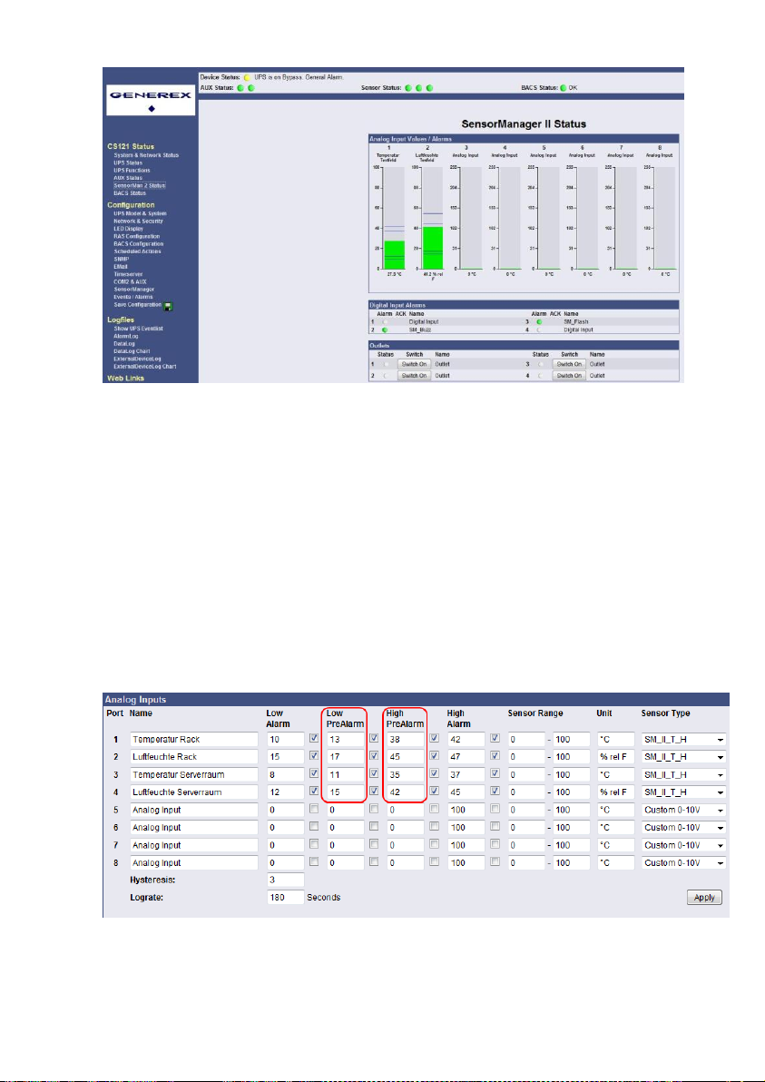
Figure 107: SENSORMANAGER II Status Site
7.3.4 Configuration
The SENSORMANAGER II provides the opportunity of the definition of pre-alarm-thresholds.
Beside the name of the input you also define here as shown above the alarm thresholds, the
sensor range and the measurement unit. Note, that the alarm values (low and high) are only
active if the fields beside the alarm values are enabled. In the drop down menu “Sensor Type”
some basic sensor models are already listed, which you can choose to set predefined values
for these types (select “Custom” to make divergent or individual settings).
You can calibrate every sensor with the Sensor Range, that means if you want to rise a
measured value for 5°C, just modify the default range from 0-100 to 5-100. Therefore you are
able to adjust the measurement values like a gauged thermometer.
With the field “Hysteresis” you define the scope within the defined value can oscillate without
releasing an alarm. This is important e.g. for temperature measurements, which are not
increasing/decreasing continuously.
At “Lograte” you can set the loop time (in sec) in which the measured values will be written into
the logfile.
Figure 108: SENSORMANAGER II Configuration Analog Inputs
89
Page 92
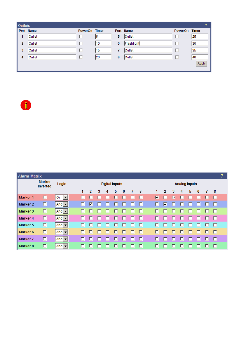
Figure 109: SENSORMANAGER II Configuration Outlets
Furthermore it is possible to attach a timer value to each Outlet. This determinates how long
an outlet will be switched (in seconds). Set the timer value to “0” if the outlet is to be switched
without any time limit.
Note: If you do not want to use a name for the Analog-, Digital Inputs or rather the
Outlets, please set the following into the single name area:
7.3.5 Alarm Matrix of the SENSORMANAGER II
The following “Alarm Matrix” gives you numerous possibilities to configure dependencies
between different alarm states and to logically combine them to different Event. This makes it
possible to process an alarm scenario in dependency of the status of several input sensors.
(For example: An alarm scenario is to be released only if two temperature sensors are out of
range or if the air condition is not active. This requires to create a new event which gets “true”
only if 2 or more other events are true)
Figure 110: Alarm matrix – Marker configuration
In the figure above is shown the alarm matrix with its 8 markers to be set or unset. Each
marker thereby is a new state on which specific alarm scenarios can be released.
For example: In the figure above is configured that the Marker1 will be set, when at the
analogue input 1 or 3 an alarm occurs. (Enabling the field “Marker Inverted” causes that
Marker1 will be unset in case of an alarm at analogue input 1 or 3.) Furthermore marker 2 will
be set, when at the digital input 2 and at the analogue input 2 an alarm state occurs at the
same time. (Means that an alarm at just one input is not sufficient for setting marker 2)
Accordingly it is possible to set (or unset) each marker in dependency of different digital and/or
analogue input states.
After having defined the conditions when markers are to be set resp. unset, you can specify
the actions to be executed when a marker will be set/unset. Therefore you have two
possibilities: The first is to handle the actions through the event configuration, described later
90
Page 93
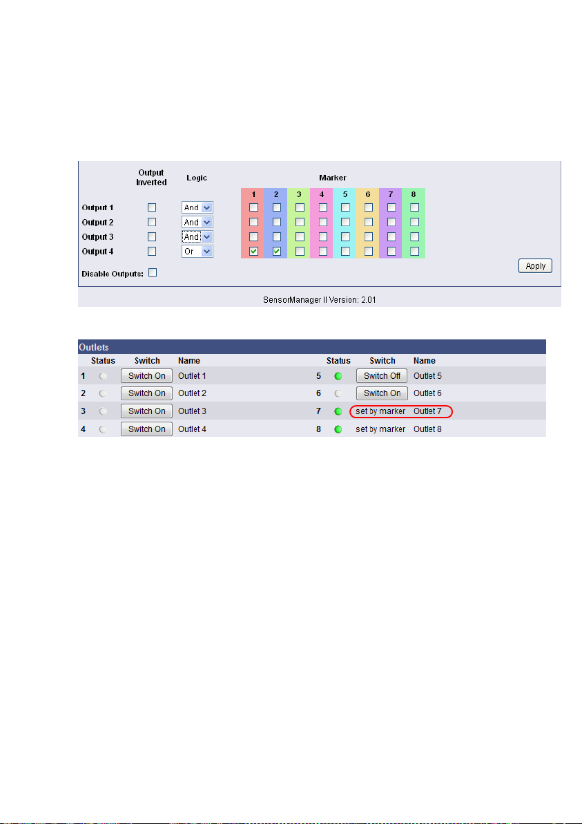
in chapter 3.2.5 Events / Alarms. This is possible because each marker has its own event
“Alarm Marker x”, which can be configured through the event configuration.
The second possibility is to switch a relay output in dependency of the statue of one or several
markers. Therefore you have the output matrix, figured as below. In this example is configured
that Output 4 is to be switched on when Marker 1 or Marker 2 is set (or the opposite way
around in case “Output Inverted” is enabled). Using the “Alarm Matrix” offers you numerous
possibilities to switch Outputs in dependency of input alarms.
Figure 111: Alarm Matrix – Switching of relay outputs
Figure 112: Alarm Matrix – Switching of relay outputs
Detection of the analog temperature values via variables:
#SM2_ANALOG0
#SM2_ANALOG1
#SM2_ANALOG2
#SM2_ANALOG3
#SM2_ANALOG4
#SM2_ANALOG5
#SM2_ANALOG6
#SM2_ANALOG7
7.4 RASMANAGER
The RAS-Manager relays alarm signals coming from monitoring devices such as UPS,
SiteManagers, contact alarms and the like to monitoring stations or email receivers. Any
computer with RAS capabilities (Windows, Linux) can be used as a monitoring station. The
only requirement is the setup of an PPPServer on the monitoring station. After the
establishment of communications between the RAS-Manager and the monitoring station, a
RCCMD signal is sent that depending on configuration can either make log entries, send
emails and SMSs or execute programs.
91
Page 94
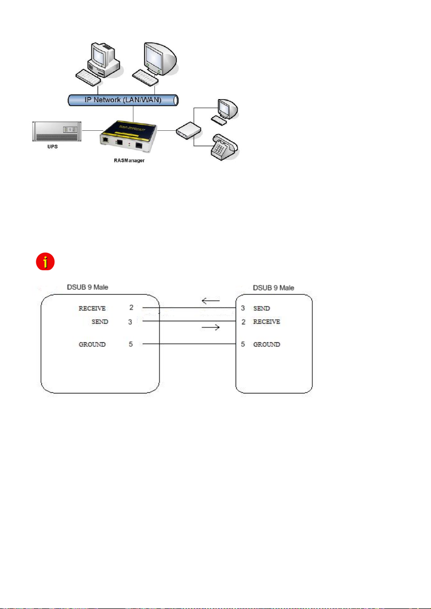
7.5 GSM Modem – Notification via SMS
The CS121 firmware version 4.17.x provides a new function, which enables the notification via
SMS. Use the CS121 configuration cable (not included) and an adapter-connector (PINs 2, 3,
5, GENEREX order number: GSM_A) for the connection of the GSM modem and the CS121.
Select into the menu “COM2 & AUX” the GSM Modem” for the COM2 mode.
Alternative, you can make a Mini8-DSUB9 cable for the Siemens GSM TMA T35i Modem by
yourself, as follows:
Figure 113: RASMANAGER network integration
Note: It is required to disable the PIN-code request of the SIM-card.
Figure 114: PIN Adjustment Adapter-Connector GSM_A
92
Page 95
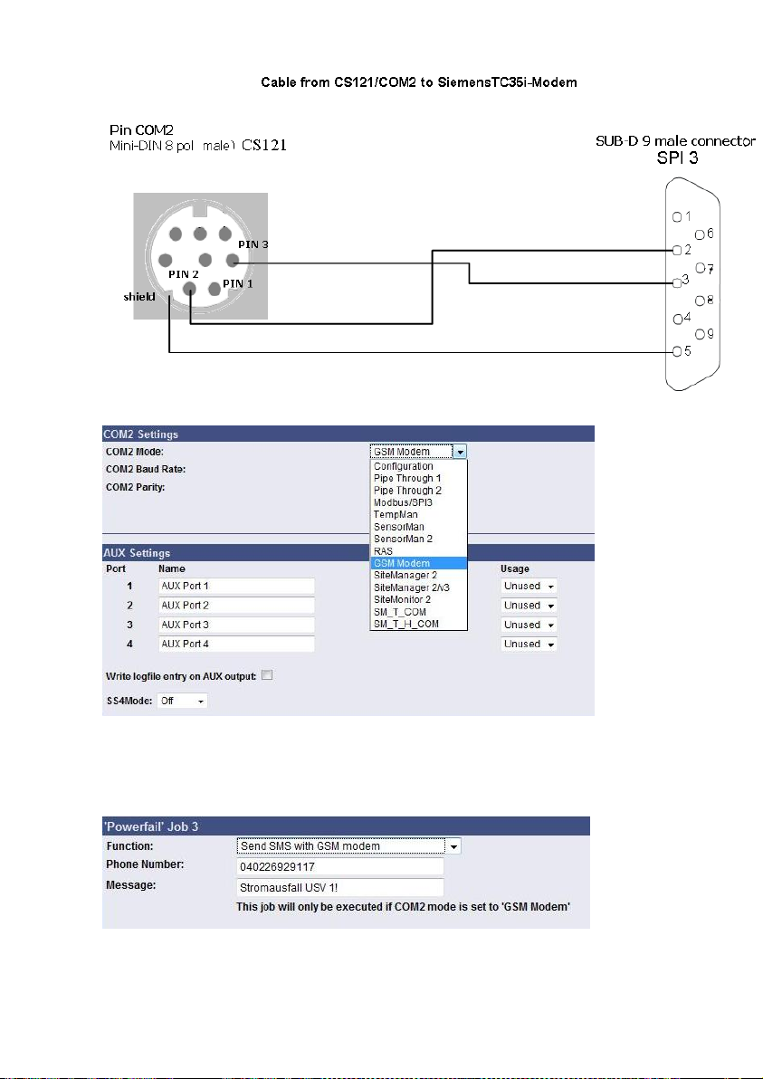
Add an accordant function via the “Events / Alarms” menu. Select the function “Send SMS with
GSM modem” for the notification via SMS and set the telephone number of the receiver and
the message.
Figure 115: Mini8-DSUB9 Cable Cross-Section
Figure 116: COM2 Mode: GSM Modem
Figure 117: Configuration of the Function
93
Page 96
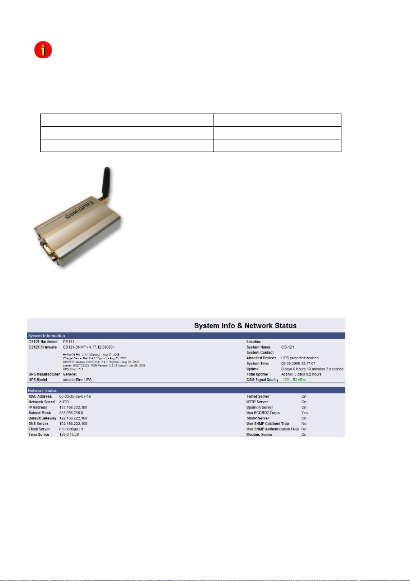
Operating Status:
LED Signaling:
SIM card not present
Slowly red flashing
SIM card active
Fast red flashing
Attention: Do not use special character in the messages! If you want to send a
Figure 118: Siemens GSM TMA T35i Modem
Into the menu “System & Network Status” you can see the signal level of the modem, to adjust
your antenna optimal. Green means a good signal is present.
SMS to several receivers, it is required, that you define a SMS job for
every receiver.
LED Status Display
7.6 LED-Matrix Display
The LED-Matrix display is a remote display unit for relaying RCCMD messages that can be
operated via the Ethernet.
94
Figure 119: GSM Signal Quality Display
Page 97
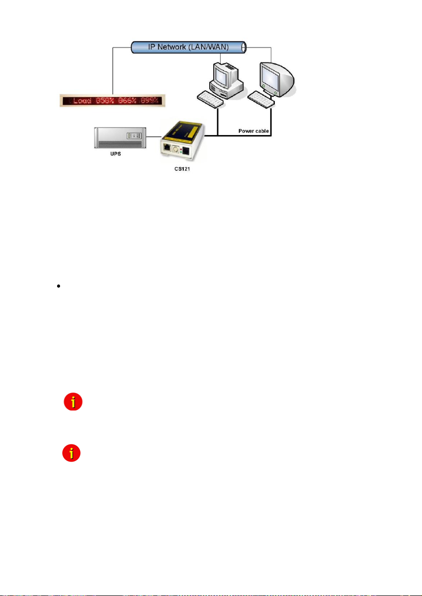
Figure 120: LED-Matrix display network integration
Any device operating as an RCCMD Sender like a computer running UPSMAN software,
RCCMD clients, CS121 Web managers and other RCCMD 2 compatible products can send
text messages or environmental data values to the LED-Matrix and can add sounding alarms
for warnings that require immediate attention. Users can also use the built in Web server
interface of the LED-Matrix to relay alarms and messages without the use of an RCCMD
Sender. The user simply enters the message into the Web browser that is to be relayed
through the LED-Matrix.
For further information and description please take a look into the LED-Matrix User Manual.
7.7 MODBUS/PROFIBUS/LONBUS
MODBUS
Modbus is a serial communications protocol for use with its programmable logic controllers
(PLCs). It has become a de facto standard communications protocol in industry, and is now the
most commonly available means of connecting industrial electronic devices. Modbus allows for
communication between many devices connected to the same network, for example a system
that measures temperature and humidity and communicates the results to a computer.
Modbus is often used to connect a supervisory computer with a remote terminal unit (RTU) in
supervisory control and data acquisition (SCADA) systems.
The CS121-series support MODBUS over IP and MODBUS over RS232 (exclude BUDGET
models) generally. Additionally, the CS121MODBUS-series also includes an RS485 interface
at COM2, which can be connected to a 485Bus-system.
Note: MODBUS response changed: Now MODBUS will respond with "-9999"
or with "-1", if values are requested, which are not available at this UPS
or other device. This shall clearly identify that this value is "not
available".
Note: If you use SNMP polling to retrieve data from the CS121, you should
disable the MODBUS port to avoid interrupts and performance slow
down.
95
Page 98
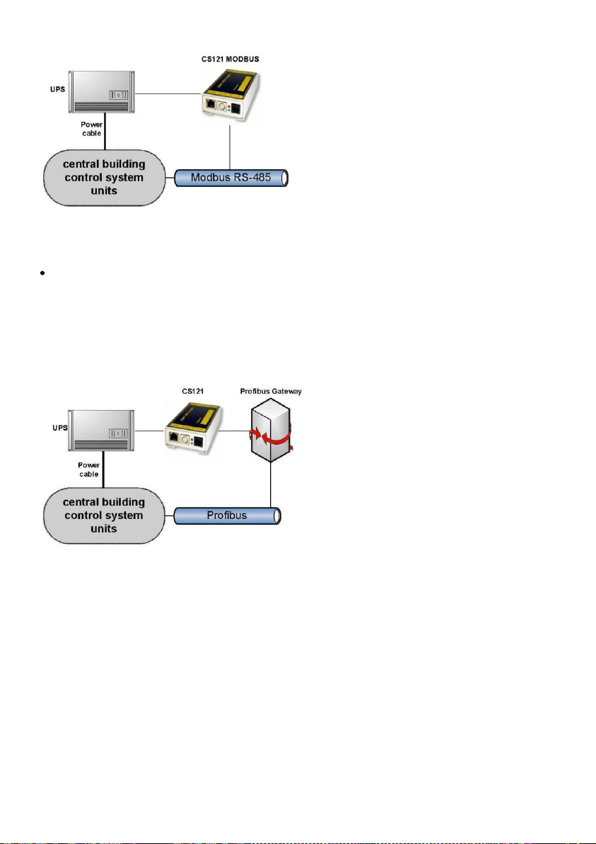
Figure 121: CS121MODBUS Installation
PROFIBUS, LONBUS and other Field busses
PROFIBUS (Process Field Bus) is the most popular type of fieldbus with more than 14 million
nodes (2006) in use worldwide. PROFIBUS was defined in 1991/1993 as DIN 19245, moved in
1996 to EN 50170 and is since 1999 included in IEC 61158/IEC 61784 Standards.
To integrate the CS121 in a Profibus environment, GENEREX offers a Profibus gateway,
which converts the MODBUS output of the CS121 into PROFIBUS environment. The
implementation of LONBUS or any other GENEREX field bus converter takes place in similar
way.
Figure 122: CS121 PROFIBUS Installation
7.8 UNMS (UPS-Network Management System)
UNMS II is a UPS network monitor designed to inform you of emergency power supply
systems problems before your clients, end-users or managers do. The UNMS as a limited
version is part of every UPSMAN license (UPSMAN suite contains UPSMAN RS232/USB UPS
Manager, UPSMON Windows client and UNMS 2 – limited to 9 UPS). The UNMS Server
Service runs intermittent checks on UPS devices you specify. When problems are
encountered, the UNMS Server Service can send notifications out to administrative contacts in
a variety of different ways (For example: Email). Current status information, historical logs, and
reports can all be accessed via a web browser (Web Console).
96
Page 99
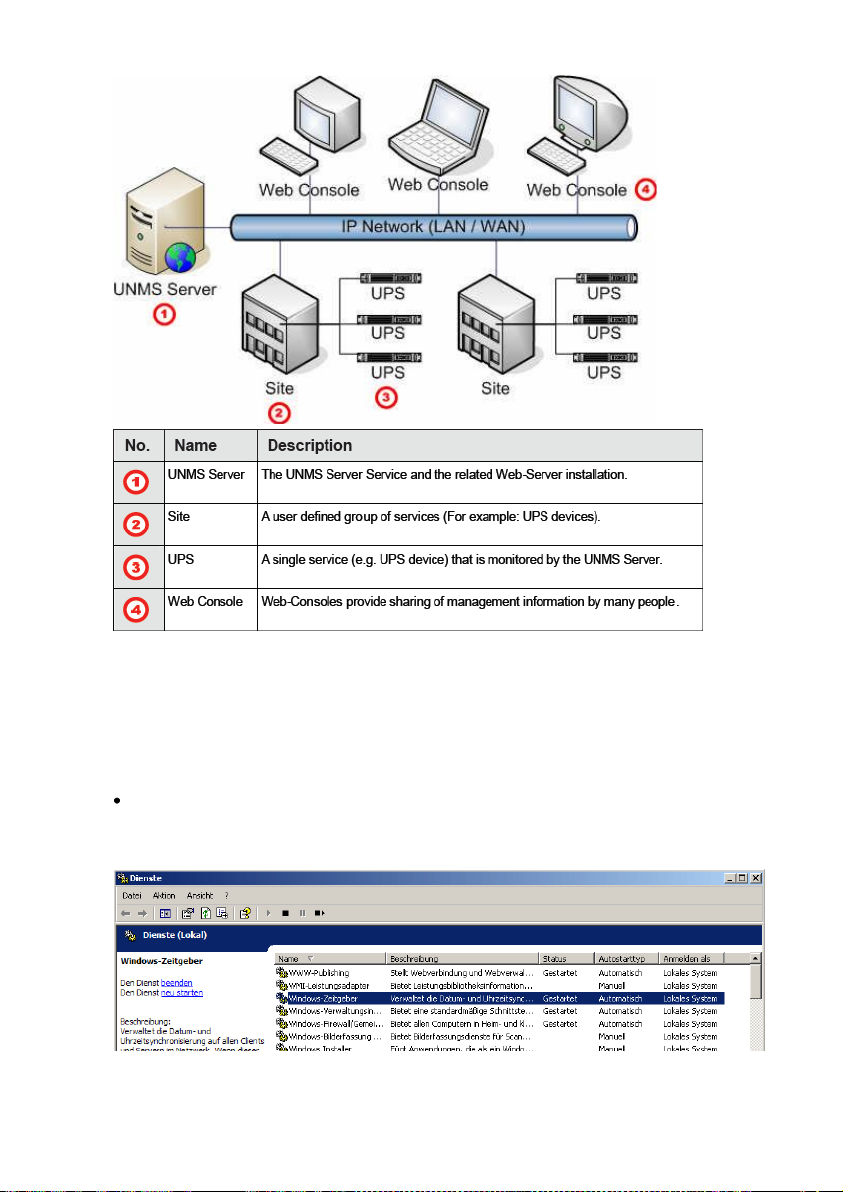
Figure 123: UNMS-Installation
8. Troubleshooting – FAQ
8.1 Solutions
Problem 1: Timeserver not at present
Solution 1: Configure a workstation as timeserver
Microsoft Windows SNTP Timeserver: As timeserver you can use any e.g. Windows PC in
your network which has access to a timeserver in the internet or a local PC clock. To use the
Microsoft Windows timeserver you have to configure and start the “Windows Time Server”
service – see screenshot in the service list:
Figure 124: MS-Timeservices
97
Page 100
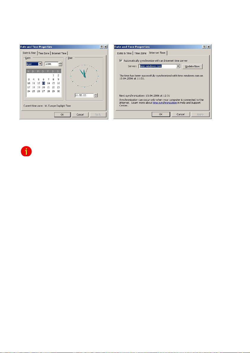
To turn your Windows computer into a timeserver, double-click on the clock in the lower right
taskbar and open the following example. After some seconds the tab “Internet Time” appears.
Click on “Internet Time” and check if the timeserver you have chosen here works correctly.
After having configured and started your Microsoft Windows Timeserver you have to reboot
your computer and check the Event Logfile of Windows to ensure, the service was started
correctly. In this case, you can configure your CS121 Timeserver using the IP-address of this
Windows computer.
Note: Please check if your computer is reachable through the network. You
At Windows Server 2003 and 2008 it is required to enable the NTP server into the registry
manually. Open the following folder:
HKEY_LOCAL_MACHINE\SYSTEM\CurrentControlSet\Services\W32Time\TimeProviders\Ntp
Server
Click with the right mouse button onto “Enabled” and change the “Value Data” from 0 to 1.
After this change stop/start the W32 Time service.
may have to change the Windows Firewall settings to allow
inbound/Outbound UDP port 123.
98
 Loading...