

Page 1

™
Model 88
Operating Instructions
For 3” through 10”
(75mm—250mm)
Your Model 88 is designed to give you
years of trouble-free, profitable service.
However, no machine is better than its operator.
Read, understand and follow all safety
warnings and instructions provided with
the product. Failure to follow the warnings
and instructions may result in electric
shock and/or serious injury. Save all warnings and instructions for future reference.
SAVE THESE INSTRUCTIONS!
Page 2
Model 88™
WARNING! Read and understand all instructions. Failure to follow all instructions listed below
may result in electric shock, fire and/or serious personal injury. Replacement manuals are available
upon request at no charge, or may be downloaded
from our website, www.drainbrain.com. Instructional videos are available for download on our
website, and may be ordered. If you have any
questions or problems, please call General’s cus-
tomer service department at 412-771-6300.
SAVE THESE INSTRUCTIONS!
These instructions are intended to
familiarize all personnel with the safe
operation and maintenance
procedures for the Model 88.
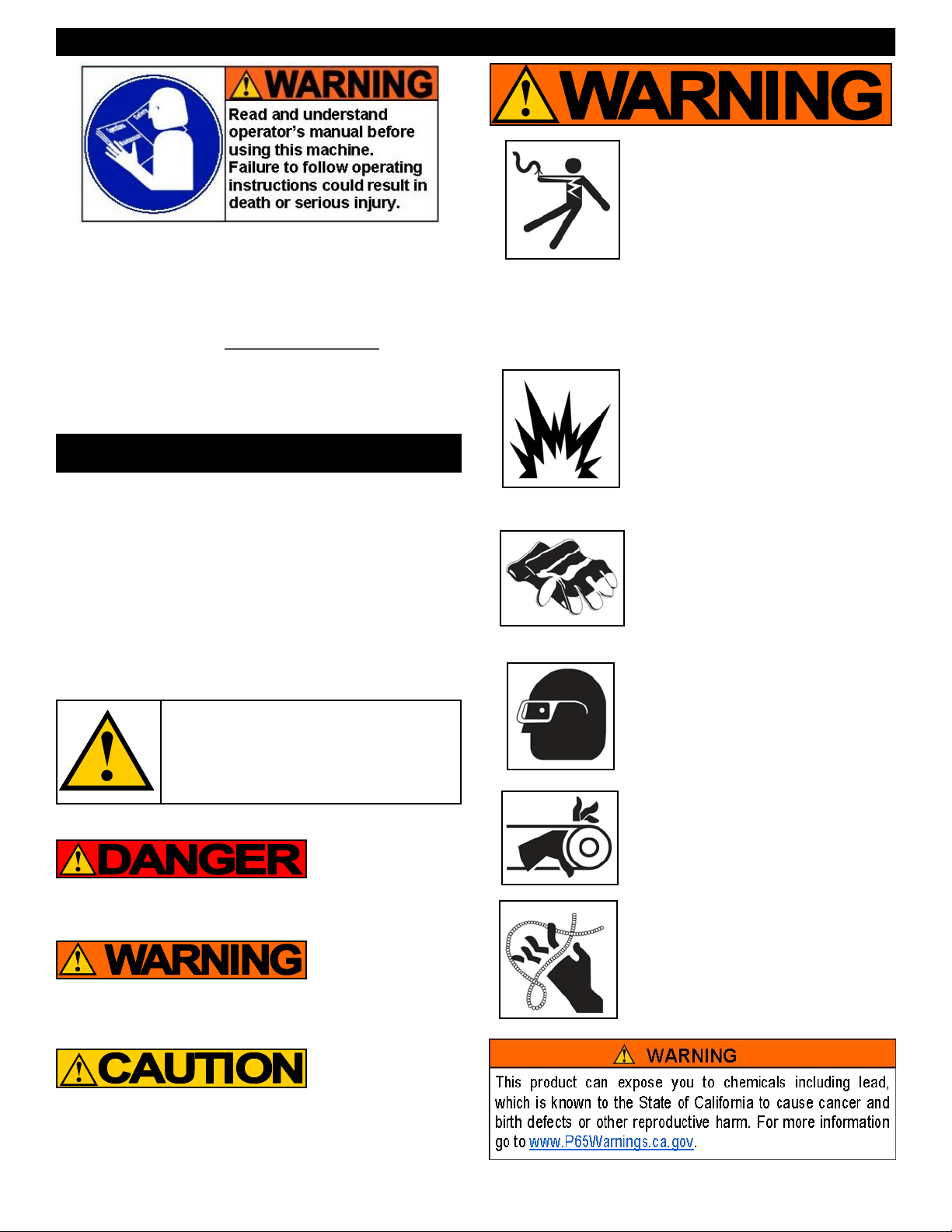
SAFETY SYMBOLS
Electric shock resulting in
death can occur if you plug
this machine into an improperly wired outlet. If the ground
wire is electrified, you can be
electrocuted by just touching
the machine, even when the
power switch is off. A ground
fault circuit interrupter will not protect you in this situation. Use a
UL approved tester to determine if
the outlet is safe.
Do not operate power tools in
explosive atmospheres, such as
in the presence of flamma-ble
liquids, gases, or dust. Power
tools create sparks which may
ignite the dust of fumes.
Only wear leather gloves.
Never use any other type of
glove, such as cloth, rubber, or
coated gloves. Never grasp a
rotating cable with a rag.
These items could become
wrapped around the cable and
cause serious injury.
This is the safety alert symbol. It is
used to alert you to potential personal
injury hazards. Obey all safety messages that follow this symbol to avoid
possible injury or death.
DANGER indicates a hazard with a high level of risk
which, if not avoided, will result in death or serious injury.
WARNING indicates a hazard with a medium level of risk
which, if not avoided, could result in death or serious injury.
CAUTION indicates a hazard with a low level of risk which,
if not avoided, will result in minor or moderate injury.
Always wear safety glasses
and rubber soled, non-slip
shoes. Use of this safety equip-
ment may prevent serious injury.
Never operate machine with
belt guard removed. Fingers
can get caught between belt and
pulley.
Do not overstress cables.
Overstressing cables may cause
twisting, kinking, or breaking of
the cable and may result in serious injury.
2
Page 3

Model 88™
GENERAL SAFETY RULES
WARNING
Read and understand all instructions. Failure to follow all instructions listed below may result in electric shock, fire, and/or
serious injury.
SAVE THESE INSTRUCTIONS!
Work Area
1. Keep work area clean and well lit. Cluttered benches and dark
areas invite accidents.
2. Do not operate power tools in explosive atmospheres, such
as in the presence of flammable liquids, gases, or dust.
Power tools create sparks which may ignite the dust or fumes.
3. Keep bystanders, children, and visitors away while operat-
ing a power tool. Distractions can cause you to lose control.
Electrical Safety
1. Grounded tools must be plugged into an outlet, properly
installed and grounded in accordance with all codes and
ordinances. Never remove the grounding prong or modify
the plug in any way. Do not use any adapter plugs. Check
with a qualified electrician if you are in doubt as to whether
the outlet is properly grounded. If the tool should electrically
malfunction or break down, grounding provides a low resistance
path to carry electricity away from the user.
2. Avoid body contact with grounded surfaces such as pipes,
radiators, ranges and refrigerators. There is an increased risk
of electric shock if your body is grounded.
3. Do not expose power tools to rain or wet conditions. Water
entering a power tool will increase the risk of electric shock.
4. Do not abuse the cord. Never use the cord to carry the tools
or pull the plug from an outlet. Keep cord away from heat,
oil, sharp edges or moving parts. Replace damaged cords
immediately. Damaged cords increase the risk of electric shock.
5. When operating a power tool outside use an outdoor exten-
sion cord marked “W-A” or “W”. These cords are rated for
outdoor use and reduce the risk of electric shock.
6. Test the Ground Fault Circuit Interrupter (GFCI) provided
with the power cord to insure it is operating correctly before
operating machine. Machine must have a properly functioning
ground fault circuit interrupter on the power cord. GFCI reduces
the risk of electric shock.
7. Extension cords are not recommended unless they are
plugged into a Ground Fault Circuit Interrupter (GFCI) found
in circuit boxes or outlet receptacles. The GFCI on the ma-
chine power cord will not prevent electric shock from the extension cords.
8. Only use proper three-wire extension cords in good condi-
tion which have three-prong grounding plugs and three-pole
receptacles which accept the tool’s plug. Use of damaged,
inferior, or other extension cords will not ground the tool. Increases the risk of electric shock and bodily injury or death.
9. Keep all electric connections dry and off the ground. Reduces the risk of electric shock.
10. DO NOT touch plugs or tools with wet hands. Reduces the
risk of electric shock.
Personal Safety
1. Stay alert, watch what you are doing and use common sense
when operating a power tool. Do not use tool while tired or
under the influence of drugs, alcohol, or medication. A mo-
ment of inattention while operating power tools may result in
serious personal injury.
2. Dress properly. Do not wear loose clothing or jewelry. Con-
tain long hair. Keep your hair, clothing, and gloves away
from moving parts. Loose clothes, jewelry, or long hair can be
caught in moving parts.
3. Avoid accidental starting. Be sure switch is off before plug-
ging in. Carrying tools with your finger on the switch or plugging
in tools that have the switch on invites accidents.
4. Remove adjusting keys or switches before turning the tool
on. A wrench or key that is left attached to a rotating part of the
tool may result in personal injury.
5. Do not overreach. Keep proper footing and balance at all
times. Proper footing and balance enables better control of the
tool in unexpected situations.
6. Use safety equipment. Always wear eye protection. Dust
mask, non-skid safety shoes, hard hat, or hearing protection
must be used for appropriate conditions.
Tool Use and Care
1. Use clamps or other practical way to secure and support the
workpiece to a stable platform. Holding the work by hand or
against your body is unstable and may lead to loss of control.
2. Do not force tool. Use the correct tool for your application.
The correct tool will do the job better and safer at the rate for
which it is designed.
3. Do not use tool if switch does not turn it on or off. Any tool
that cannot be controlled with the switch is dangerous and must
be repaired.
4. Disconnect the plug from the power source before making
any adjustments, changing accessories, or storing the tool.
Such preventative safety measures reduce the risk of starting the
tool accidentally.
5. Store idle tools out of reach of children and other untrained
persons. Tools are dangerous in the hands of untrained users.
6. Maintain tools with care. Keep cutting tools sharp and clean.
Properly maintained tools, with sharp cutting edges are less likely
to bind and are easier to control.
7. Check for misalignment or binding of moving parts, break-
age of parts, and any other condition that may affect the
tool’s operation. If damaged, have the tool serviced before
using. Many accidents are caused by poorly maintained tools.
8. Only use accessories that are recommended by the manufacturer for your model. Accessories that may be suitable for
one tool may become hazardous when used on another tool.
Service
1. Tool service must be performed only by qualified repair personnel. Service or maintenance performed by unqualified repair
personnel could result in a risk of injury.
2. When servicing a tool, use only identical replacement parts.
Follow instructions in the Maintenance section of this manual. Use of unauthorized parts or failure to follow Maintenance
Instructions may create a risk of electric shock or injury.
3
Page 4

Model 88™
SPECIFIC SAFETY RULES
This is the safety alert symbol. It is used to alert
1. Only wear leather gloves. Never use any other type of glove,
such as cloth, rubber, or coated gloves. Never grasp a rotating
cable with a rag. These items could become wrapped around the
cable and cause serious injury.
2. Never operate machine with belt guard removed. Fingers can
get caught between belt and pulley.
3. Do not overstress cables. Keep leather-gloved hand on the
cable for control when machine is running. Overstressing cables
because of an obstruction may cause twisting, kinking, or breaking of the cable and may result in serious injury.
4. Machine is designed for ONE-PERSON operation. Operator
must control foot switch and cable.
5. Keep hands away from rotating cable. Hand may be caught in
the moving parts resulting in serious injury.
6. Be careful when cleaning drains where cleaning chemicals
have been used. Avoid direct contact with skin and eyes. Drain
cleaning chemicals can cause serious burns as well as damage
the cable.
7. Do not operate machine if operator or machine is standing
in water. Will increase risk of electrical shock.
8. Wear safety glasses and rubber soled, non-slip shoes. Use
of this safety equipment may prevent serious injury.
9. Before starting each job, check that the cable is not broken
or kinked, by checking for wear or breakage. Always replace
worn out (kinked or broken) cables with genuine GENERAL replacement cables.
10. Only use this tool in the application for which it was de-
signed. Follow the instructions on the proper use of the machine. Other uses or modifying the drain cleaner for other appli-
cations may increase risk of injury.
Ground Fault Circuit Interrupter (GFCI)
Your machine is equipped with a ground fault circuit interrupter, which
protects you against shock if a short circuit should occur. Check that
receptacle is properly grounded. Test the GFCI before each use.
1. Plug into 120-volt receptacle.
2. Push test button. Indicator light will go out and power to machine
should cut off.
3. If light does not go out when test button is pushed, equipment
should not be used until proper repairs can be made.
you to potential personal injury hazards. Obey all
safety messages that follow this symbol to avoid
possible injury or death.
Electric shock resulting in death can occur if you
plug this machine into an improperly wired outlet. If
the ground wire is electrified, you can be electrocuted
by just touching the machine, even when the power
switch is off. A ground fault circuit interrupter will not
protect you in this situation. Use a UL approved tester to
determine if the outlet is safe.
Do not overstress cables. Overstressing cables may
cause twisting, kinking, or breaking of the cable and may
result in serious injury.
4. To restore power after test, push reset button. With the reset
button depressed, if the machine doesn't start, stops while running, or if the operator experiences a mild shock, do not use the
machine! Tag the machine out of service and take it to a motor
repair center or return it to the factory for repairs.
THE SECTION OF CORD BETWEEN THE WALL PLUG
AND THE GFCI IS NOT IN THE PROTECTED CIRCUIT.
FEATURES
Air
Switch
Lifting
Handle
Motor
switch
Safety Slip
Clutch
NOTE: Do not operate machine if warning labels on the switch box
and power cord are missing or illegible.
Adjustable
Front Post
Cables and Connectors
Your machine comes with one of three cable connectors; “G” connectors for General® cables, “L” connectors to match Electric Eel®-type
cables, and “R” connectors to match Ridgid®-type cables.
To couple the “G” cables, slide
the tab on the male connector
into the slot in the female connector, then turn the ring until
the button pops up.
To disconnect, push the button in with
the coupling wrench. Then turn the ring
until it lines up with the slot in the connector and slide cables apart.
4
Folding
Handle
Sliding
Collars
Reducer
Lifting
Handle
Gear
Chuck
Cover
Grease
Fitting
Cable
Drive
Coupling
Page 5

Model 88™
To couple “L” cables, line up the solid pin in the male connector with
the L-shaped notch in the female connector. Depress the spring pin
and push the male connector into the female connector. Turn until the
spring pin snaps into place.
To disconnect, push down the spring pin
with the coupling wrench. Turn the male
connector a quarter turn, then pull the
cables apart.
Cable Application Chart (Table 1)
Cable
Size
*1-1/4” 3” - 10” Proflex™
1-1/4” 3” - 6” Flexichain™
**7/8” 2” - 3” Proflex™
* Proflex™ cables are available in 4, 8, and 10 ft. lengths. Heavy-duty
5/8” inner spring and extra space outer spring sections also available.
** Available only with “L” Connector (Part #6L78). Adapter required
(Part #78L-CDC).
Pipe
Size
Cable Type Typical
Applications
Large Drains,
Long Runs, Roots
Tight Traps, Diffi-
cult Bends, Roots
Small Drains (No
Roots)
Cutter Application Chart (Table 2)
Catalog #
“G”
Cutter
Spear
Head
Hook Auger
2" UCutter
3" Heavy
Duty
Side
Cutter
3" Heavy
Duty
Saw
Blade
4"
Rotary
Saw
Blade
Retrieving
Tool
Note: There are no fixed rules for what cutter to use. If one tool
doesn't take care of a stoppage, simply try another.
Connector
G-SHD L-SHD
G-HA L-HA
G-2UC L-2UC
G-3HDSC L-3HDSC
G-3HDB L-3HDB
G-4RSB L-4RSB For cutting roots.
G-RTR-2 L-RTR-2
“L”
Connector
Typical
Applications
Starting tool, gets
the water flowing
Starting tool, to
remove loose
objects.
Starting tool, for
cutting and
scraping.
Finishing tool, for
scraping inside
edges of pipe.
Heavy duty tool
for cutting roots.
For removing
loose objects and
broken cables.
OPERATION
Sectional Cables
With General® Connectors
10GF 1-1/4" x 10 ft. Flexichain
10GP 1-1/4" x 10 ft. Proflex
Sectional Cables
Compatible with Electric Eel® Connectors
4LPS 1-1/4" x 4 ft. 1/2" Proflex/Extra Space
8LF 1-1/4" x 8 ft. Flexichain
8LP 1-1/4" x 8 ft. 1/2" Proflex
8LPS 1-1/4" x 8 ft. 1/2" Proflex/Extra Space
10LF 1-1/4" x 10 ft. Flexichain
10LP 1-1/4" x 10 ft. 1/2" Proflex
10LHD 1-1/4" x 10 ft. 5/8" Proflex
6L78 7/8" x 6 ft. 7/16" Proflex
General makes cables and cutters to fit equipment manufactured by others.
We have no affiliation with these companies.
Make sure the motor switch is in the ‘OFF’ position before con-
necting to power source!
Make sure you have 12 - 15 feet (3.6 - 4.5m) of clear area around
the drain opening to allow the machine to operate safely.
1. Attach a cutter to the female end of a section of cable. Be sure
the locking ring is aligned so that the plunger pin clicks into
place. The Spear Head or 2" U-Cutter are good tools to start with
to get the line open. After the water is flowing, switch to one of
the larger cutters.
2. On cables with “G” connectors, be sure the connector locking
ring is turned far enough for the plunger pin to click into place.
On cables with “L” connectors, twist the cables until the plunger
pin pops out.
3. Push the section into the drain opening as far as it will go. Depending on the location of the clog or bends in the line, you may
be able to put in several lengths of cable.
4. On machines using the “G” cables, you can connect the male
connector of the cable to the machine by twisting the knurled ring
on the Cable Drive Coupler until the plunger pin clicks into place.
On machines using “L” cables, twist the cable until the plunger
pin springs out.
5
Page 6

Model 88™
DO NOT ALLOW TOO MUCH SLACK IN THE CABLE
BETWEEN MACHINE AND DRAIN OPENING SINCE
THIS CAN CAUSE CABLE WHIPPING.
5. Pull the machine back until slack is out of
the cable. Put the motor switch in for-
ward. Stand behind the machine and
press the air switch. Machine will move
toward drain opening. Allow cable to
work its way through drain by itself.
6. If you have difficulty getting the cable
through the trap, you can use the Cable
Feeding Tool (Cat. # CF).
Place air switch on the floor beside drain
opening. Press cable feeding tool so that it
pinches the cable against edge of pipe.
With motor switch in forward, step on the
air switch and run machine until cable
moves freely into drain.
7. When all but the last two or three feet of cable section have fed
into the line, stop the machine. If you are using the “G” connec-
tors, simply twist the knurled ring on the Cable Drive Coupler 90°
and detach the cable from the machine. If you are using the “L”
cables, disconnect the cable from the machine using the Coupling Wrench.
8. If the cable begins to buckle or twist, stop by taking your hand off
the air switch. The motor will spin in the opposite direction and
relieve the twist. When you reach some resistance in the drain,
move the motor switch to reverse and run for several seconds.
Then switch to forward again. Allow cable to stop spinning before
going in other direction. Repeat until water starts to flow.
9. After drain is clear, retract the cable by putting machine in reverse and backing machine away from drain opening. Allow cable to move out of drain at its own rate. Disconnect sections as
they emerge from drain.
Hint: It's often helpful to have a small stream of water running in the
line to wash the cuttings away while the machine is in operation and
after.
SPECIAL OPERATIONS
FOLDING HANDLE
To make the Model 88 more compact, it is equipped with a folding
handle. By lifting up the sliding collars on each side of the handle,
you can fold it forward. When the handle is raised, the collars will
drop into position, locking the handle in place.
DISCONNECT FROM POWER SOURCE BEFORE
ADJUSTING CLUTCH TENSION!
1. Remove the clutch cover and
loosen the screw in the large
hex nut on the front of the
clutch. Turn the nut in to increase tension and out to
reduce it. Then tighten the
screw.
2. If you do not intend to change the tension on the clutch very
often, you can fold over one of the metal tabs on the washer
between the nut and the body of the clutch so that it presses
firmly on the hex nut. You can, of course, alter the pressure on
the clutch at a later date by bending the tab back up, adjusting
the nut, and bending a different tab against the nut.
3. Remember that the clutch is put on the machine to protect your
cables! Therefore, do not tighten to the point where sections will
be damaged before the clutch slips.
MAINTENANCE
DISCONNECT MACHINE FROM POWER SOURCE
BEFORE PERFORMING MAINTENANCE !
To keep your machine operating smoothly, it is essential that all bearings and bushings be lubricated. Oiling moving parts is particularly
important where machine comes in contact with sand, grit and other
abrasive material.
CABLE MAINTENENCE
To get maximum service from your cables, be
sure that they are clean and well oiled. This not
only provides running lubrication but greatly
extends the life of the cables as well. Our
SNAKE OIL is ideally suited for this purpose,
since it not only lubricates the cables, it deodorizes them as well.
GEAR REDUCER MAINTENANCE
The Model 88 has an oil capacity of 1.25 pints. The manufacturer of
the gear reducer recommends #2 EP oil when operating conditions
are between 15 and 60 degrees F, and #4 EP oil when operating conditions are between 60 and 165 degrees F.
The Model 88 gear reducers are shipped with #4 EP oil. The oil
should be changed after the first 1,000 hours of use, and thereafter
every 12 months or 5,000 hours of use, whichever comes first. The
following steps should be followed for refilling:
SAFETY SLIP CLUTCH
The safety slip clutch is located between the motor and the Cable
Drive Coupler. It is designed to protect your cables from breakage and
is factory preset to slip at 18-20 ft-lbs. of torque. Under normal usage
of your machine, no adjustments need to be made to the clutch. If you
find it necessary to change the clutch tension, the following procedure
should be used:
DISCONNECT FROM POWER SOURCE
BEFORE LUBRICATING!
1. Remove the Vent/Fill plug at the top of the gear reducer.
2. Remove the Level plug at the middle of the side of gear reducer.
3. Use a funnel or other device to add lubricant until it appears at
the side opening (Capacity: 1.25 pints).
6
Page 7

Model 88™
Trouble Shooting Guide (Table 3)
Problem Probable Cause Solution
Cable tangles, kinks or breaks. Operator forcing the cable. Do not force the cable. Let the cutter do the work.
Too much slack between machine and drain. Do not allow slack between machine and drain.
Cable used in wrong size drain line. A cable that is too large or too small in diameter for a line is
more likely to kink. (Consult Table 1—Cable Applications.)
Cable exposed to acid. Clean and oil cables regularly.
Safety Clutch tension too high. Loosen Safety Clutch to allow to slip.
Motor stops while switch is
depressed. Restarts when
pedal is re-depressed.
Motor turns in one direction but
not other.
Motor turns but cable does not. Safety Slip Clutch engaged. Do not force cable.
Ground Fault Circuit
Interrupter trips and will not
reset.
Hole in air switch or hose. Replace damaged component.
Reverse switch failure. Replace reverse switch.
Damaged power cord or extension cord. Replace cords.
Short circuit in motor. Take motor to authorized repair center.
Faulty ground fault circuit interrupter. Replace Ground Fault Circuit Interrupter.
7
Page 8

Model 88™
General Wire Spring Co.
1101 Thompson Avenue
McKees Rocks, PA 15136
412-771-6300 www.drainbrain.com
© General Wire Spring Co. 2018 C-88OI-1018
 Loading...