

Page 1
CALIBRATABLE
7-FUNCTION
PSYCHROMETER
USER’S MANUAL
EP8710
Please read this manual carefully and
thoroughly before using this product.
Page 2

TABLE OF CONTENTS
Introduction . . . . . . . . . . . . . . . . . . . . 2 –4
Key Features . . . . . . . . . . . . . . . . . . . . . . . 4
What’s in the Box . . . . . . . . . . . . . . . . . . . 5
Product Overview . . . . . . . . . . . . . . . . 5 –8
Setup Instructions . . . . . . . . . . . . . . . 8 –9
Install Battery . . . . . . . . . . . . . . . . . 8 –9
Operating Instructions . . . . . . . . . . . 9 – 12
Making Basic Measurements . . . . 9 – 11
Using the External Temperature Probe .11
Tracking Min and Max Levels . . . . . . . 12
Calibrating the Meter . . . . . . . . . . . 13 – 16
Specifications . . . . . . . . . . . . . . . . . . . . . 17
Operating & Maintenance Tips . . . . . . . . 18
Warranty Information . . . . . . . . . . . . . . . 19
Return for Repair Policy . . . . . . . . . . . . . 20
INTRODUCTION
Thank you for purchasing General Tools
& Instruments’ EP8710 Calibratable
7-Function Psychrometer. Please read this
user’s manual carefully and thoroughly
before using the instrument.
The EP8710 can measure any
environment’s ambient temperature,
relative humidity (RH), dew point and wet
bulb temperatures and other condensationrelated parameters. These measurements
are typically made by three groups of users:
2
Page 3

• Water damage restoration contractors
• HVAC/R system installers and technicians
• Professionals charged with monitoring
and maintaining the environment of
facilities such as office buildings,
greenhouses, food and equipment storage
facilities, wineries, freezers, shipping
containers, computer rooms, labs,
libraries, museums and saunas.
The dew point is the temperature below
which the water vapor in a volume of air at
a given constant barometric pressure will
condense into liquid water at the same rate
at which it evaporates. Condensed water is
called dew when it forms on a solid surface.
Another way to think of the dew point is as
an air saturation temperature associated
with relative humidity (RH). A high RH value
indicates that the dew point is close to the
current ambient air temperature. At 100%
RH, the dew point temperature is equal to
the ambient temperature because the air is
completely saturated with water.
The wet bulb temperature is the
temperature that a volume of air would
have if it were cooled to saturation (100%
RH) by the evaporation of water into it, with
the latent heat coming from the volume of
air. It is the lowest temperature that can be
reached under current ambient conditions
by the evaporation of water only. The wet
3
Page 4

bulb temperature is the temperature you
feel when your skin is wet and exposed to
moving air as opposed to the actual air
temperature—the dry bulb temperature.
Because the EP8710 includes an external
temperature probe, the instrument can also
measure and display two additional
parameters of particular importance to
HVAC/R system installers and technicians:
1) the surface temperature of a solid object,
the object's internal temperature (if it can
be penetrated), or the temperature of a
liquid or gas
2) a solid object’s condensation
temperature—the difference between its
surface temperature and the dew point
temperature
The EP8710 is powered by one “9V” battery
(included).
KEY FEATURES
• Jumbo backlit display with 2-line readout
• Field calibratable using optional 33% and
75% salts
• Data hold and Min/Max functions
• External probe for measuring internal and
surface temperatures of objects and fluids
• °F/°C switch
• 20-minute Auto Power Off function
• Low battery indicator
4
Page 5

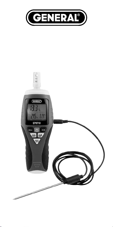
WHAT’S IN THE BOX
The EP8710 comes fully assembled in a box
along with a sensor protection cap, an
external temperature probe, a “9V” battery
and this user’s manual.
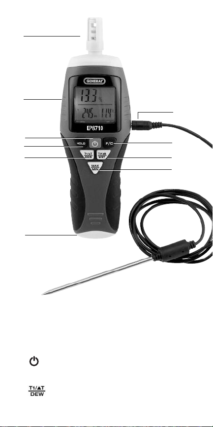
PRODUCT OVERVIEW
Figure 1 shows all of the controls, indicators
and physical structures on the front, top and
bottom of the EP8710. Figure 2 shows all
text and icons that could appear on the
unit’s LCD. Familiarize yourself with the
positions and functions of all buttons,
structures and icons before moving on to
the Setup Instructions and Operating
Instructions.
5
Page 6
A
B
J
C
D
E
F
Fig. 1. The EP8710’s controls, indicators
and physical structures
A. Humidity and temperature sensors
B. LCD
C. (Power on/off) button
D.
HOLD
button
E. (Ambient/dew point temperature)
6
button
I
H
G
Page 7

F. Battery compartment
MAX/MIN
G.
button
H. Probe/condensation/wet bulb
temperature) button
F/C
button
I.
J. External temperature probe plugged into
jack on side of unit
Fig. 2. All possible display indications and
their meanings
A. Low battery icon
B. Data hold indicator
C. Minimum reading indicator
D. Maximum reading indicator
E. °C indicator
F. °F indicator
G. Probe (T2)/wet bulb temperature readout
H. Wet bulb (Wb) temperature indicator
7
Page 8

I.
Condensation temperature
(available only with external probe plugged
in). An object’s condensation temperature is
the difference between its surface
temperature and the dew point
temperature.
J. Probe temperature (T2) indicator
(available only with external probe
plugged in)
K. Ambient (T1)/dew point temperature
readout
L. Dew point temperature indicator
M.⌬T indicator (available only with external
probe plugged in). ⌬T is the difference
between ambient temperature (T1) and
the surface or internal temperature (T2)
of a solid or fluid touched or penetrated
by the probe.
N. Ambient (T1) temperature indicator
O. Relative humidity (RH) readout
()indicator
SETUP INSTRUCTIONS
INSTALL BATTERY
1. The meter’s battery compartment (Fig. 1,
Callout F) is accessible from the bottom
of the unit. Use a Phillips-head
screwdriver to loosen the single screw in
the back of the unit that holds the yellow
battery compartment cover in place. Set
the cover and screw aside.
8
Page 9

2. Plug the included “9V” battery into the
wired socket inside the compartment. The
terminals of the battery and the socket
mate in only one way, with the smaller
male terminal plugging into the larger
female terminal.
3. Replace the battery compartment cover
and tighten the screw to secure it to
the housing.
OPERATING
INSTRUCTIONS
MAKING BASIC MEASUREMENTS
Before making any measurements, rotate
the sensor protection cap with your thumb
and index finger so its three vents are open
to the ambient environment from both the
front and back. Press the button to
power on the meter. The upper display will
immediately begin reading out the RH value
of the environment. The lower left display
will immediately begin reading out the
ambient temperature (indicated by the text
T1 at its left). The lower right display will
immediately begin reading out the wet
bulb temperature (indicated by the text
Wb
at its left).
To display the dew point temperature
(instead of ambient temperature) on the lower
left readout, press the button. The
9
Page 10

reading will be accompanied by the symbol
DP
at its left. To return to displaying ambient
temperature, press the button again.
By default, the EP8710 displays ambient,
dew point, wet bulb, and objects’ and fluids’
surface and internal temperatures in °C.
To switch to °F
, press the
F/C
button.
To hold the readings on all three displays,
press the
button. The text
HOLD
will
HOLD
appear at the right of the RH readout. To
“unfreeze” the display and resume showing
HOLD
real-time readings, press the
again. This will cause
HOLD
to disappear
button
from the RH readout.
Pressing any button turns on the green
backlight for 10 seconds.
To extend the life of the “9V” battery
powering the EP8710, the unit’s Auto Power
Off (APO) function will automatically shut
down the instrument if no front-panel
buttons are pressed within any 20-minute
period.
To disable the APO function
, power
on the unit in a special way by pressing and
holding the
HOLD
button while pressing the
button. The LCD will confirm that you
are disabling the APO function by displaying
its complete set of icons (see Fig. 2) until
you release the
HOLD
button. The APO
function will be enabled the next time you
power on the unit in the normal way.
10
Page 11

To power off the EP8710
, press and hold
the button for at least 3 seconds.
USING THE EXTERNAL
TEMPERATURE PROBE
The external temperature probe included
with the EP8710 can measure the surface
temperature of any solid object, the internal
temperature of an object (if it can be
penetrated), or the temperature of a liquid
or gas.
The probe plugs into a jack on the right side
of the EP8710. With the probe plugged in:
• A third parameter—⌬T—is available
by pressing the button. ⌬T is the
difference between ambient temperature
(T1) and the surface or internal
temperature (T2) of a solid or fluid
touched or penetrated by the probe.
• Two additional parameters—T2 and
a solid object’s condensation
temperature—are available by pressing
the button. T2 is the surface or
internal temperature of a solid or fluid
touched or penetrated by the probe. An
object’s condensation temperature is
the difference between its surface
temperature and the dew point
temperature.
11
Page 12

TRACKING MIN AND
MAX LEVELS
After being powered on, the EP8710
automatically operates in “Recording” mode
for the purpose of tracking maximum and
minimum RH and ambient temperature
measurements.
To display the maximum RH and ambient
temperature
meter was powered on, press the
button once. The text
values measured since the
MAX/MIN
MAX
will appear at
the right of the upper (RH) readout, and the
upper and lower left readouts will display
the highest values of RH and ambient
temperature measured since power on.
To display the minimum RH and ambient
temperature
meter was powered on, press the
button again. The text
values measured since the
MAX/MIN
MIN
will replace
MAX
at the right of the upper (RH) readout, and
the upper and lower left readouts will
display the lowest values of RH and ambient
temperature measured since power on.
To return to displaying real-time RH and
ambient temperature readings, press the
MAX/MIN
button a third time. The text
MIN
will disappear from the RH readout.
12
Page 13

CALIBRATING THE METER
Your EP8710 was calibrated at the factory,
so its measurements should remain within
their specified tolerance for several years.
However, you can re-calibrate the unit
yourself to reassure yourself of the accuracy
of readings, especially after the instrument
has been operated for many hours in a
dusty environment.
To calibrate the EP8710, you must use
two jars of standard calibration salt: one
containing a 33% solution of MgCl and
the other a 75% solution of NaCl. Both are
available for purchase from General as part
numbers SKUs HR33 and HR75.
Before beginning the calibration
procedure—which takes at least 2-1/2
hours to complete—you must disable the
APO function so the instrument can remain
on for more than 20 minutes.
APO function
way by pressing and holding the
button while pressing the button.
Following is the calibration procedure:
1. With the unit powered on and the APO
function disabled, rotate the sensor
protection cap to open its three vents and
expose the humidity sensor to the
environment.
, power on the unit in a special
To disable the
HOLD
13
Page 14

2. Turn the unit upside-down and insert the
sensor structure in the opening of the
33% salt bottle after removing the bottle’s
cap. The fit should be tight, with no air
leaking into the bottle.
3. Leave the unit upside-down in the 33%
salt bottle for at least 40 minutes.
4. Check the upper RH readout without
turning the unit right-side up or removing
the sensor structure from the bottle. If the
reading is between 32.5% and 33.5%,
the meter is operating within its RH
specification. Remove the meter from the
33% salt bottle and proceed to step 10.
5. If the reading is not between 32.5% and
33.5%, the unit is out of calibration at
this reference point. To adjust its
calibration, press the
HOLD
and
F/C
buttons at the same time to enter
calibration mode. The lower left readout
will switch from displaying ambient
temperature to showing the following:
“- -. 1”
6. If the reading is less than 32.5%, press
the
F/C
button as many times as
necessary to increase it to a value
between 32.5% and 33.0%. If the
reading is greater than 33.5%, press the
HOLD
button as many times as necessary
to decrease it to a value between 33.0%
and 33.5%.
14
Page 15

7. Store the calibration adjustment you have
just made by pressing the button.
8. Remove the unit from the 33% salt
bottle and repeat Steps 2 through 7 to
calibrate the unit to the 33% reference a
second time. When you press the
and
F/C
buttons to enter calibration
HOLD
mode this time, the left readout will
display the following: “- -.2”. Two
calibrations constitute a cycle.
9. Store the calibration adjustment you
have just made by pressing the
button. The EP8710 is now calibrated to
the 33% reference standard. Remove
the unit from the 33% salt bottle.
10. Insert the EP8710 upside-down in the
opening of the 75% salt bottle after
removing the bottle’s cap. The fit should
be tight, with no air leaking into the bottle.
11. Leave the unit upside-down in the 75%
salt bottle for at least 40 minutes.
12. Check the upper RH readout without
turning the unit right-side up or
removing the sensor structure from the
bottle. If the reading is between 74.5%
and 75.5%, the meter is operating
within its RH specification. Remove the
EP8710 from the 75% salt bottle.
13. If the reading is not between 74.5% and
75.5%, the unit is out of calibration at
this reference point. To adjust its
15
Page 16

calibration, press the
HOLD
and
F/C
buttons at the same time to enter
calibration mode. The lower left readout
will switch from displaying ambient
temperature to showing the following:
“- -. 1”
14. If the reading is less than 74.5%, press
F/C
the
button as many times as
necessary to increase it to a value
between 74.5% and 75.0%. If the
reading is greater than 75.5%, press the
HOLD
button as many times as
necessary to decrease it to a value
between 75.0% and 75.5%.
15. Store the calibration adjustment you
have just made by pressing the
button.
16. Remove the unit from the 75% salt
bottle and repeat Steps 10 through 15
to calibrate the unit to the 75%
reference a second time. When you
press the
HOLD
and
F/C
buttons to
enter calibration mode this time, the
lower left readout will display the
following: “- -.2”. Two calibrations
constitute a cycle.
17. Store the calibration adjustment you
have just made by pressing the
button. The EP8710 is now calibrated to
the 75% reference standard.
16
Page 17

SPECIFICATIONS
Ambient Temperature Measurement Range:
14° to 122°F (-10° to 50°C)
Ambient Temperature Measurement
Accuracy: 1.8°F (±1°C)
External Temperature Probe Measurement
Range: 14° to 158°F (-10° to 70°C)
External Temperature Probe Measurement
Accuracy: ±1.8°F (±1.0°C)
External Probe Cord Length: 48 in. (1.22m)
Temperature Measurement Resolution: 0.1°
RH Measurement Range: 0 to 99.9%
RH Measurement Accuracy:
±3% from 5% to 95% RH
RH Measurement Resolution: 0.1%
Response Time: <80 seconds
Display Size: 1.7 in. (43mm) diagonal
Current Consumption: <15mA
Battery Life: 60 hours (typical)
Dimensions of Instrument:
7.56 x 2.40 x 1.57 in. (192 x 61 x 40mm)
Dimensions of Box:
7.76 x 3.66 x 1.58 in. (197 x 93 x 40mm)
Weight (without battery): 3.77 oz. (107g)
Power Source: (1) “9V” battery (included)
17
Page 18

OPERATING &
MAINTENANCE TIPS
When the icon appears on the top
line of the display (Fig. 2, Callout A), it’s time
to replace the “9V” battery that powers the
instrument (although measurements will
remain valid for several hours after the icon
first appears). To replace the battery, follow
the instructions on pages 8 and 9.
To prevent dust and moisture from
degrading the performance of the humidity
and temperature sensors, after each
measurement session rotate the sensor
protection cap to close its three vents.
Do not operate the EP8710 in the presence
of a flammable or explosive gas or near an
arc welder or induction heater.
After subjecting the unit to a large change
in ambient temperature, wait at least 30
minutes before making measurements to
guarantee the accuracy of readings.
Remove the battery when storing the unit or
when you do not expect to use it for an
extended period of time (months rather than
weeks).
Do not drop or disassemble the EP8710 or
immerse it in water.
18
Page 19

WARRANTY
INFORMATION
General Tools & Instruments’ (General’s)
EP8710 Calibratable 7-Function
Psychrometer is warranted to the original
purchaser to be free from defects in
material and workmanship for a period of
one year. Subject to certain restrictions,
General will repair or replace this
instrument if, after examination, the
company determines it to be defective in
material or workmanship.
This warranty does not apply to damages
that General determines to be from an
attempted repair by non-authorized
personnel or misuse, alterations, normal
wear and tear, or accidental damage. The
defective unit must be returned to General
Tools & Instruments or to a Generalauthorized service center, freight prepaid
and insured.
Acceptance of the exclusive repair and
replacement remedies described herein is a
condition of the contract for purchase of this
product. In no event shall General be liable
for any incidental, special, consequential or
punitive damages, or for any cost, attorneys’
fees, expenses, or losses alleged to be a
consequence of damage due to failure of,
or defect in any product including, but not
limited to, any claims for loss of profits.
19
Page 20

RETURN FOR REPAIR
POLICY
Every effort has been made to provide you
with a reliable product of superior quality.
However, in the event your instrument
requires repair, please contact our Customer
Service to obtain an RGA (Return Goods
Authorization) number before forwarding
the unit via prepaid freight to the attention
of our Service Center at this address:
General Tools & Instruments
80 White Street • New York, NY 10013
212-431-6100
Remember to include a copy of your proof
of purchase, your return address, and your
phone number and/or e-mail address.
GENERAL TOOLS & INSTRUMENTS
80 White Street New York, NY 10013-3567
PHONE (212) 431-6100 FAX (212) 431-6499
TOLL FREE (800) 697-8665
e-mail: sales@generaltools.com
www.generaltools.com
Specifications subject to change without notice
©2013 GENERAL TOOLS & INSTRUMENTS
NOTICE - WE ARE NOT RESPONSIBLE FOR TYPOGRAPHICAL ERRORS.
20
EP8710 User’s Manual
MAN#EP8710
5/3/13
 Loading...