

Page 1

6:1 POCKET INFRARED
THERMOMETER
USER’S MANUAL
IRT105
Please read this manual carefully and thoroughly before using this product.
Page 2

TABLE OF CONTENTS
Introduction . . . . . . . . . . . . . . . . . . . . . . . . . . . 3
Key Features . . . . . . . . . . . . . . . . . . . . . . . . . . . 4
Safety Instructions . . . . . . . . . . . . . . . . . . . . . . 4
What’s in the Blister Pack . . . . . . . . . . . . . . . . 5
Product Overview . . . . . . . . . . . . . . . . . . . . 5 –6
Setup Instructions . . . . . . . . . . . . . . . . . . . 6 –7
Install Two Batteries . . . . . . . . . . . . . . . . 6 –7
Operating Instructions . . . . . . . . . . . . . . . 7 – 16
Making Basic Measurements . . . . . . . . . 7 –8
Advanced Measurement Modes
and Functions . . . . . . . . . . . . . . . . . . . . 8 – 11
Accounting for Emissivity . . . . . . . . . .11 – 13
Making Accurate Measurements . . . . 14 – 16
Specifications . . . . . . . . . . . . . . . . . . . . . . . . . 17
Warranty Information . . . . . . . . . . . . . . . . . . . 18
Return for Repair Policy . . . . . . . . . . . . . . . . 19
Spanish Translation . . . . . . . . . . . . . . . . 20 – 39
French Translation . . . . . . . . . . . . . . . . . 40 – 59
2
Page 3

INTRODUCTION
Thank you for purchasing General Tools & Instruments’
IRT105 6:1 Pocket Infrared Thermometer. Please read this
user’s manual carefully and thoroughly before using the
instrument.
The IRT105 is a small and lightweight non-contact
thermometer that measures the surface temperature of an
object from a distance by using an IR sensor to measure its
thermal radiation. A laser pointer defines the target area
(spot) whose temperature is being measured.
The thermometer has a wide measurement range of -22° to
482°F (-30° to 250°C) and a distance-to-spot ratio of 6:1.
These two specifications—as well as its adjustable emissivity
and its high basic measurement accuracy (±3°F above 32°F)
—make the IRT105 ideally suited for applications in food
processing, electrical troubleshooting, and automotive and
HVAC equipment maintenance. In applications such as these,
an infrared thermometer is the only instrument capable of
taking the temperature of a surface that may be impossible to
reach or too hot or cold to touch.
The IRT105 comes in a blister pack with two nonrechargeable CR2032 Lithium-ion batteries to power its
thermometer and laser pointer.
3
Page 4

KEY FEATURES
• Optimized measurement range
• Basic accuracy of ±3°F
• Adjustable emissivity
• Fast response time
• Min and Max measurement modes + Measurement
Lock mode
• Selectable °F or °C unit
• Large LCD
• Separate batteries for thermometer and laser
• Auto power off
• Small and light and easy to use
SAFETY INSTRUCTIONS
CAUTION!
The IRT105’s targeting laser is a Class II type that emits less
than 1mW of power between 630nm and 660nm. Avoid direct
eye contact with laser light radiation. U.S. law prohibits
pointing a laser beam at aircraft; doing so is punishable by a
fine of up to $10,000 and imprisonment.
4
Page 5

WHAT’S IN THE BLISTER PACK
The IRT105 comes in a plastic blister pack with two CR2032
batteries, a wrist strap and this user’s manual.
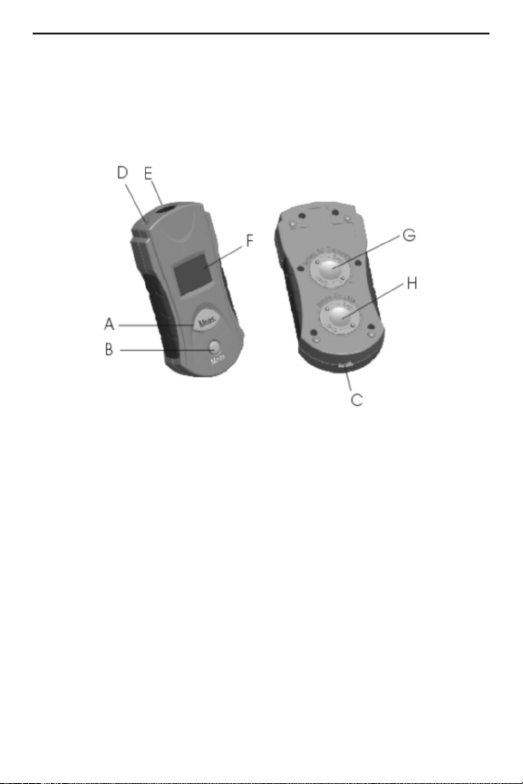
PRODUCT OVERVIEW
Figure 1 shows the locations of the controls, indicators and
physical features of the IRT105.
Fig. 1. The IRT105’s controls, indicators
and physical features
A. Meas. (measure) button
B. Mode button
C. Wrist strap attachment bar
D. Laser pointer
E. IR sensor window
F. Liquid-crystal display
G. Thermometer battery compartment
H. Laser battery compartment
5
Page 6
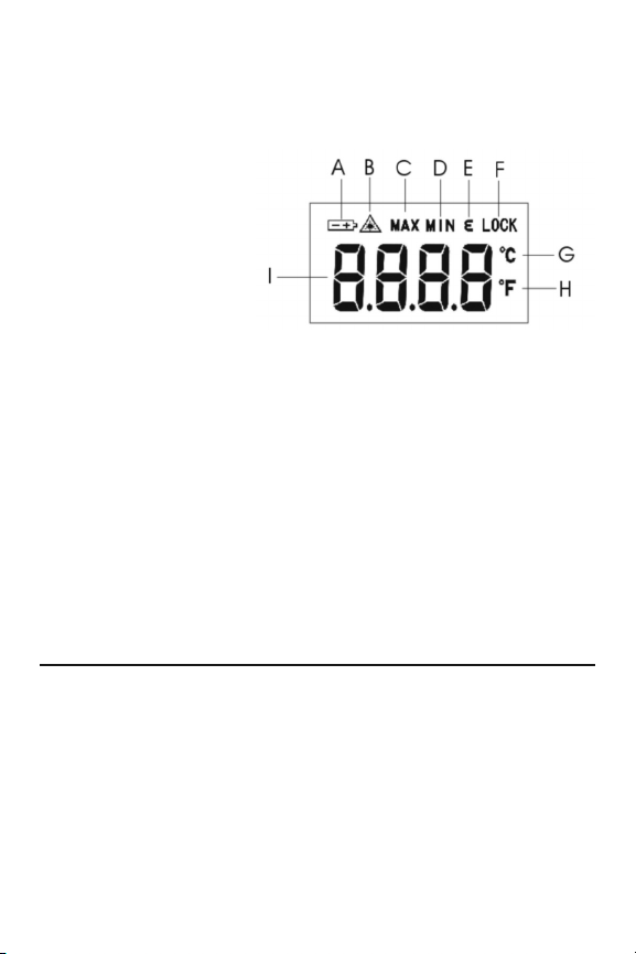
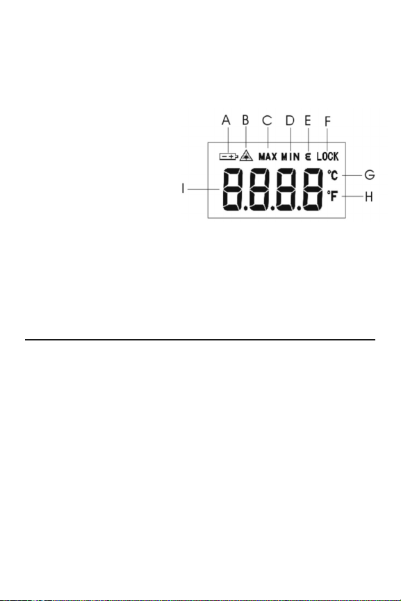
Figure 2 shows the icons and text that may appear on the
display. Familiarize yourself with the locations of these
controls and the meanings of these icons before moving on to
the setup and operating instructions.
Fig. 2.
All possible display
indicators and
their meanings
A. Low Battery icon
B. Laser Enabled icon
C. Displaying highest measurement
D. Displaying lowest measurement
E. Operating in emissivity selection mode
F. Operating in measurement lock mode
G. Celsius unit selected
H. Fahrenheit unit selected
I. Measured value
SETUP INSTRUCTIONS
INSTALL TWO BATTERIES
Two CR2032 batteries (included) must be installed in separate
compartments in the back of the IRT105 (callouts G and H of
Fig. 1) to activate its thermometer and laser pointer. To open
either compartment, place the tips of your thumb and index
finger against the bumps on the round compartment cover
and turn clockwise. Insert each battery so the writing
6
Page 7

stenciled on it faces you. Then replace both covers and
secure them by turning them counterclockwise.
When replacing a battery, you may need to slide the tip of a
pin under it to dislodge it. Each compartment is equipped with
a pin slot (at the four o’clock) position for that purpose.
OPERATING INSTRUCTIONS
MAKING BASIC MEASUREMENTS
To make a quick measurement with the IRT105, point the
front of the unit at a surface, press the Meas. (measure)
button, hold it for at least one second, and then release the
button. The temperature of the surface will be displayed
instantly on the LCD in Celsius or Fahrenheit units. Note that
when you release the Meas. (measure) button the reading will
be held for 15 seconds and then disappear as the IRT
automatically powers off (to extend battery life).
By default, the laser pointer turns on when the Meas.
(measure) button is pressed and turns off when the button is
released. The laser’s default state is indicated by the
presence or absence of the Laser Enabled icon (callout B of
Fig. 2).
To change the laser’s default state from on to off, first
power off the IRT by pressing and holding the Mode button.
Then power on the unit in a special way by pressing and
holding the Mode and Meas. buttons at the same time. Note
that after doing this the Laser Enabled icon will no longer
appear on the top line of the display.
To return the laser’s default state to on, simply press and
hold the Meas. button as you would to make a quick
measurement. Note that after doing so the Laser Enabled icon
will reappear on the top line of the display.
7
Page 8
To temperature-scan the surfaces of a room or any
environment, press the Meas. (measure) button and keep
pressing it as you point the IRT in various directions. Note that
the display tracks the different temperatures of different
surfaces in real time.
To power off the IRT105, either press and hold the Mode
button or let the auto power off function turn the IRT off after
15 seconds of inactivity.
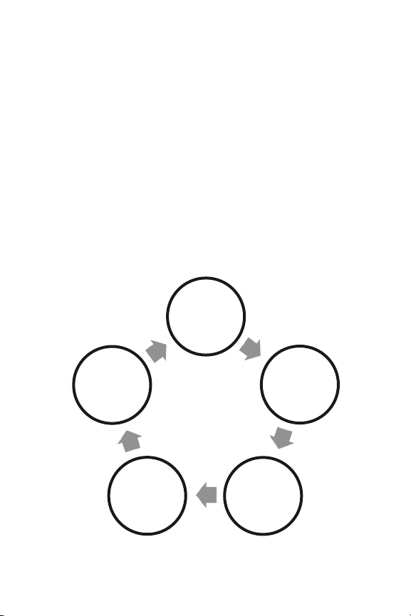
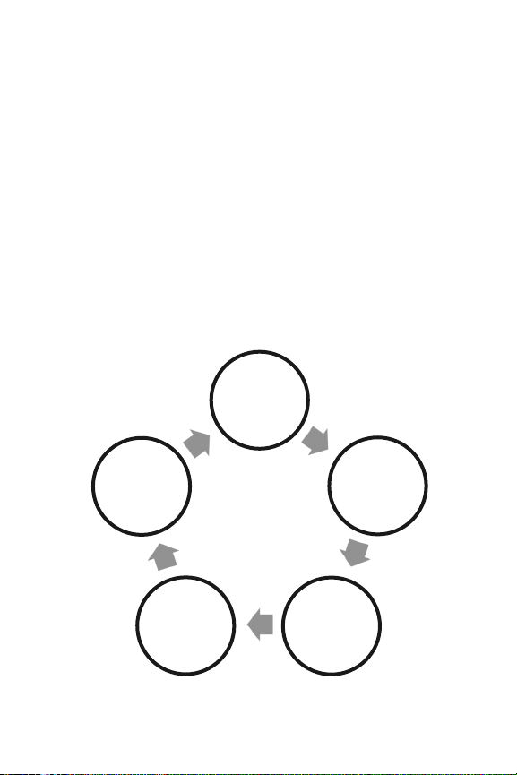
ADVANCED MEASUREMENT MODES
AND FUNCTIONS
The Mode button below the Meas. button is the gateway to
the IRT105’s five advanced measurement and selection
modes (see Figure 3).
Press 1x to
enter MAX
Measurement
mode
Press 5x
to enter
Emissivity
Selection
mode
Press 4x to
enter °C/°F
Selection
mode
Press 2x to
enter MIN
Measurement
mode
Press 3x to
enter
Measurement
Lock mode
Fig. 3. The Mode button provides access to the IRT105’s five
advanced measurement and selection modes
8
Page 9

1. MAX Measurement mode—To identify the hottest surface in
an environment, press the Meas. button to power on the IRT.
Then (within 15 seconds) press the Mode button once. This
will cause the text MAX to appear blinking on the top line of
the display. Then press the Meas. (measure) button. This
changes MAX from blinking to constant, indicating operation
in MAX Measurement mode.
Within 15 seconds, press and hold the Meas. (measure)
button and begin to scan surfaces within sight. Note that in
MAX mode the display no longer tracks the temperatures of
scanned surfaces in real time. Instead, it shows the highest
temperature measured since the Meas. (measure) button
was pressed. Also note that the maximum temperature is
held only for 15 seconds after the Meas. (measure) button is
released, causing the IRT to begin counting down to auto
power off.
To exit MAX mode and return to real-time temperature
scanning, press the Mode button. If the IRT auto powers off
while in MAX mode, it will not resume operation in MAX mode
when powered on again. It will resume operation in real-time
measurement mode.
2. MIN Measurement mode—The flip side of MAX mode, MIN
mode is entered by powering on the IRT105 and pressing the
Meas. (measure) button twice. This causes the text MIN to
appear blinking on the top line of the display. Pressing the
Meas. button changes MIN from blinking to constant,
indicating operation in MIN Measurement mode.
In MIN mode, the display shows the lowest temperature
measured so far during a scanning session. Like MAX values,
MIN values are held for only 15 seconds. To exit MIN mode
and return to real-time scanning, press the Mode button.
9
Page 10

3. Measurement Lock mode—Pressing the Mode button three
times with the IRT powered on causes the word LOCK to
appear blinking on the top line of the display. Pressing the
Meas. (measure) button changes LOCK from blinking to
constant, indicating operation in Measurement Lock mode.
In this mode, you need not hold the Meas. (measure) button
while scanning. Surface temperatures are measured and
displayed in real time, and the IRT’s 15-second auto power off
function is disabled. Although Lock mode makes scanning
easier, it has a potential downside: the disabling of auto power
off. If you forget to exit Lock mode and then leave the IRT105
powered on for a long time, you run the risk of discharging the
thermometer battery. So remember to exit Lock mode after
using it by pressing the Mode button.
Before entering Measurement Lock mode, you should disable
the laser pointer—by powering off the IRT and then powering
it back on in a special way by pressing and holding the Meas.
and Mode buttons at the same time, as explained earlier.
Doing so will prevent accident discharging of the laser’s
battery in Lock mode over time with the auto power off
function disabled. Disabling the pointer is also a safety
precaution. If you were to leave the IRT unattended with the
laser on after putting it into Lock mode, a curious child could
enter the room and stare directly at the pointer to investigate
the source of the unusual light.
4. °C/°F Selection mode—Pressing the Mode button
four times with the IRT powered on causes the symbol of the
current default temperature unit (°C or °F) on the right side of
the display to change from constant to blinking. Pressing the
Meas. (measure) button while the term is blinking switches
all displayed readings to the other unit until the default unit is
changed again.
10
Page 11

5. Emissivity Selection mode—Pressing the Mode button five
times with the IRT powered on causes the Greek letter to
appear blinking on the top line of the display. Unlike in other
modes, the blinking icon indicates that a new mode has
already been entered—in this case, Emissivity Selection
mode.
The factory-set default emissivity value of the IRT105 is 0.95.
To enter the emissivity value of your target surface material:
• Locate the material in Table 1 in the shaded box,
Accounting for Emissivity.
• Press the Meas. (measure) button as many times as
necessary to change the display from the factory-set
default value of 0.95 to the desired value. Note that each
press of the button increases the displayed value by 0.01.
After five presses, starting at 0.95, the displayed value will
be 1.00. The next press will change the value to 0.10—the
lowest possible emissivity setting. Each subsequent press
of the Meas. (measure) button will increase the value by
0.01 units.
• When you have reached the desired emissivity value, press
the Mode button to store the setting. The IRT105 will use this
value in its temperature calculations until you change it.
ACCOUNTING FOR EMISSIVITY
Emissivity is the ability of an object to reflect or absorb
IR radiation (energy). Because the IRT105 measures the
amount of infrared energy emitted by a surface, the IRT’s
measurements are most accurate when they take into
account the characteristic emissivity of the target material.
A perfectly absorbent surface (called a black body) has an
emissivity (represented by the Greek letter
) of 1; it
11
Page 12

absorbs 100% of the thermal energy hitting it. An object with
an emissivity of 0.8 absorbs 80% of IR energy and reflects
20% of it. All emissivity values fall between 0 and 1; as a rule,
the shinier the surface, the lower its emissivity. The default
emissivity setting of the IRT105 is 0.95.
To maximize the accuracy of IRT105 measurements, you
should enter the actual emissivity of the target surface via the
front panel buttons and display, as explained on pp. 10 and
11. To do so, first determine the emissivity of the surface
whose temperature you wish to measure from Table 1.
Note from the double entries for aluminum, copper, steel and
asbestos paper in the table that emissivity is only slightly
dependent on temperature. Consequently, you can confidently
use the table’s emissivity numbers for your target material
even if it is at a different temperature than specified.
Compensating for emissivity will particularly improve the
accuracy of measurements of surfaces with emissivities
nearer to zero than to the default IRT105 setting of 0.95.
Table 1. Emissivities of common materials
Material Temperature (°F/°C) Emissivity
Gold (pure, highly polished) 440/227 0.02
Aluminum foil 81/27 0.04
Aluminum disc 81/27 0.18
Aluminum (household, flat) 73/27 0.01
Aluminum (polished plate) 400/227 0.04
1070/577 0.06
Aluminum (rough plate) 78/26 0.06
Aluminum (oxidized) 390/199 0.11
1110/599 0.19
Aluminum surfaced roofing 100/38 0.22
Tin (bright tinned iron sheet) 77/25 0.04
12
Page 13

Nickel wire 368/187 0.10
Lead (99.95% pure, unoxidized) 260/127 0.06
Copper 390/199 0.18
1110/599 0.19
Steel 390/199 0.52
1110/599 0.57
Zinc (galvanized sheet iron, bright) 82/28 0.23
Brass (highly polished) 476/247 0.03
Brass (hard rolled, polished w/lines) 70/21 0.04
Iron galvanized (bright) ——- 0.13
Iron plate 68/20 0.69
Rolled sheet steel 71/21 0.66
Oxidized iron 212/100 0.74
Wrought iron 70/21 0.94
Molten iron 2550-3270/1299-1399 0.29
Copper (polished) 70-242/21-117 0.02
Copper (scraped, shiny, not mirrored) 72/22 0.07
Cooper (plate,
Brick (red, rough) 70/21 0.93
Brick (silica, unglazed rough) 1832/1000 0.80
Concrete ——— 0.94
Glass (smooth) 72/22 0.94
Granite (polished) 70/21 0.85
Marble (light gray, polished) 72/22 0.93
Asbestos board 74/23 0.96
Asbestos paper 100/38 0.93
700/371 0.95
Asphalt (paving) 39/4 0.97
13
Page 14
MAKING ACCURATE MEASUREMENTS
The IRT105 has a distance-to-spot (D:S) ratio of 6:1. This
means that the target area (spot) whose infrared radiation
(temperature) is being measured increases in diameter by
1 inch for every 6 inches you move away from the target.
Conversely, the diameter of the target area measured
decreases by 1 inch for every 6 inches you move closer to
the target.
All IR thermometers (IRTs), including the IRT105, take the
average temperature of all objects within a circular target
area (spot). Although the distance “D” in the D:S ratio is
defined as a linear value and the “S” defines the diameter of
the spot (see Fig. 4), the critical parameter is the target area.
Depending on the distance to the target (the object whose
temperature you want to measure), the target area may
include both the target and background objects near or
behind the thermometer’s field of view, which defines the
target area or spot.
Fig. 4. The IRT105’s field of view
14
Page 15

To explain the relationship between D:S ratio and
measurement accuracy, consider how the IRT105 would be
used to measure the temperature of a small AC motor
suspected of overheating. The motor measures approximately
2
1 ft x 1 ft, so it has an area of 1 ft
. If the IRT105 is used to
make the measurement from 12 ft. away, the reading will
2
have a large error. At this distance, the target area is 2 ft
.
Therefore, the IRT105 will measure not just the temperature
of the motor, but also the temperature of the physical
surroundings in its field of view (see Fig. 5, top), and average
the two readings.
How inaccurate would the measurement be? If the motor’s
operating temperature is 200°F and the background
temperature is 75°F, and the motor’s area is half the target
area at the measurement distance, the following equation
gives the average temperature of the target area:
Tavg = (Tmotor + Tbackground) ÷ 2
Solving for Tavg, we get (200 + 75) ÷ 2 or 137.5°F., which is
what the IRT105 would display. In other words, trying to
measure the temperature of the motor from 12 ft. away
introduced an error of (200-137.5) ÷ 200, or 31% into the
measurement. In this case, the measured temperature was
31% below the motor’s actual temperature because the
background is cooler than the motor.
15
Page 16

To eliminate measurement error, the IRT must be moved close
enough so the motor is the only object in the target area (see
2
Fig. 5, bottom). For a motor with an area of 1 ft
and using the
IRT105, with a D:S ratio of 6:1, the optimum measurement
distance would be 6 ft.
Fig. 5. Measuring a motor’s temperature from the wrong
(top) and right (bottom) distance.
16
Page 17

SPECIFICATIONS
Measurement Range -22° to 482°F (-30° to 250°C)
Measurement Accuracy ±3°F (2°C) or 2% of reading
(whichever is greater) above 32°F
(0°C); ±5°F (3°C) or 2% of reading
(whichever is greater) below 32°F
Measurement Repeatability 1% of reading or 1°C
Distance-To-Spot (D:S) Ratio 6:1
Emissivity Adjustable from 0.1 to 1 in 0.01
Response Time 500 msec for 95% response
Display Type/Size/Resolution LCD/1.0 x 0.8 in.
Laser Class/Power/Wavelength Class II/<1mW/630 to 660nm
Response Wavelength 8 to 14 um
Auto Power Off After 15 seconds of inactivity
Thermometer Battery Life 50 hours, typical
Current Consumption <5mA w/laser off
Operating Temperature 32° to 104°F
Storage Temperature -4° to 140°F
Dimensions 4.25 x 2.05 x 0.98 in.
Weight 1.41 oz. (40g)
Power Source Two CR2032 (3V) non-
increments (factory set to 0.95)
(25 x 19mm)/±0.1°C
(0° to 40°C)@<75% R.H.
(-20° to 60°C)@<85% R.H.
(108 x 52 x 25mm)
rechargeable Lithium-ion cells
17
Page 18

WARRANTY INFORMATION
General Tools & Instruments’ (General’s) IRT105 6:1 Pocket
Infrared Thermometer is warranted to the original purchaser
to be free from defects in material and workmanship for a
period of one year. Subject to certain restrictions, General will
repair or replace this instrument if, after examination, the
company determines it to be defective in material or
workmanship.
This warranty does not apply to damages that General
determines to be from an attempted repair by non-authorized
personnel or misuse, alterations, normal wear and tear, or
accidental damage. The defective unit must be returned to
General Tools & Instruments or to a General-authorized
service center, freight prepaid and insured.
Acceptance of the exclusive repair and replacement remedies
described herein is a condition of the contract for purchase of
this product. In no event shall General be liable for any
incidental, special, consequential or punitive damages, or for
any cost, attorneys’ fees, expenses, or losses alleged to be a
consequence of any damage due to failure of, or defect in any
product including, but not limited to, any claims for loss of
profits.
18
Page 19

RETURN FOR REPAIR POLICY
Every effort has been made to provide you with a reliable
product of superior quality. However, in the event your
instrument requires repair, please contact our Customer
Service to obtain an RGA (Return Goods Authorization)
number before forwarding the unit via prepaid freight to the
attention of our Service Center at this address:
General Tools & Instruments
80 White Street
New York, NY 10013
212-431-6100
Remember to include a copy of your proof of purchase, your
return address, and your phone number and/or e-mail
address.
19
Page 20

6:1 TERMÓMETRO
INFRARROJO
DE BOLSILLO
MANUAL DEL USUARIO
IRT105
Lea cuidadosamente el manual antes de utilizar este producto.
Page 21

TABLA DE CONTENIDOS
Introducción . . . . . . . . . . . . . . . . . . . . . . . . . . . . . . . . . 22
Características principales . . . . . . . . . . . . . . . . . . . . . 23
Instrucciones de Seguridad . . . . . . . . . . . . . . . . . . . . 23
Contenido del paquete . . . . . . . . . . . . . . . . . . . . . . . . . 23
Información general del producto . . . . . . . . . . . 24 – 25
Instrucciones de Instalación . . . . . . . . . . . . . . . . . . . . 26
Instale 2 baterías . . . . . . . . . . . . . . . . . . . . . . . . . . . 26
Instrucciones de Operación . . . . . . . . . . . . . . . . 26 – 36
Toma para Medidas Básicas . . . . . . . . . . . . . . 26 – 27
Medidas avanzadas: Modo y Funciones . . . . . 28 – 31
Tomando en cuenta la Emisividad . . . . . . . . . 31 – 34
Toma para medidas exactas . . . . . . . . . . . . . . 34 – 36
Especificaciones . . . . . . . . . . . . . . . . . . . . . . . . . . . . . 37
Información de Garantía . . . . . . . . . . . . . . . . . . . . . . . 38
Políticas de Devolución por Reparaciones . . . . . . . . . 39
21
Page 22

INTRODUCCION
Gracias por adquirir el Termómetro Infrarrojo de Bolsillo
IRT105 6:1 de General Tools & Instruments. Por favor, lea
cuidadosamente el manual del usuario antes de utilizar este
instrumento.
El IRT105 es un Termómetro sin contacto, pequeño y liviano
el cual mide la temperatura de la superficie de un objeto a
distancia por medio de un sensor IR que mide la radiación
térmica. El indicador láser define el área o el lugar específico
de donde se requiere tomar la temperatura.
El termómetro tiene un amplio rango de medición de -22° a
482°F (-30° a 250°C) y un índice de localización a distancia
de 6:1.
Éstas dos características, al igual que su emisividad ajustable
y alta precisión básica de medición (±3°F por arriba de 32°F)
convierte al IRT105 en la herramienta ideal y en la más
apropiada para aplicaciones en el proceso de alimentos,
resolución de problemas eléctricos, automóviles y equipo de
mantenimiento para calefacción, ventilación y aire
acondicionado. En aplicaciones como éstas, el termómetro
infrarrojo es el único instrumento que cuenta con la
capacidad de tomar la temperatura de una superficie
imposible de alcanzar o que esté muy caliente o fría para
tocarla.
El IRT105 viene en un paquete con dos baterías CR2032 no
recargables para alimentar el termómetro y el indicador láser.
22
Page 23

CARACTERÍSTICAS PRINCIPALES:
• Optimo rango de medición
• Precisión básica de ±3°F
• Emisividad ajustable
• Tiempo de respuesta inmediata
• Modo de medición mínima y máxima + modo de
medición de bloqueo
• Unidad para seleccionar °F ó °C
• Pantalla amplia de líquido de cristal (LCD)
• Baterías independientes para el termómetro y el láser
• Apagado automático
• Compacto, liviano y de fácil de usar
INSTRUCCIONES DE SEGURIDAD
¡PRECAUCION!
El objetivo del láser del IRT105 es Clase II, el cual emite
menos de 1mW de energía entre 630nm y 660nm. Evite el
contacto directo de la luz láser con los ojos. La ley de los
Estados Unidos prohíbe apuntar hacia una aeronave con un
rayo láser; de hacerlo, es castigable hasta por una multa de
$10,000 y encarcelamiento.
CONTENIDO DEL PAQUETE
El IRT105 viene en un paquete con dos baterías CR2032, una
banda para la muñeca de la mano y un manual de usuario.
23
Page 24

INFORMACION GENERAL
DEL PRODUCTO
Figura 1: Muestra la ubicación de los controles, indicadores y
características físicas del IRT105.
Figura 1: Controles, indicadores y características
físicas del IRT105.
A. Botón de Medida (Meas.)
B. Botón de Modo (Mode)
C. Barra para fijar la banda de la muñeca de la mano
D. Indicador Láser
E. Ventana de sensor IR
F. Pantalla de cristal líquido (LCD)
G. Compartimiento para la batería del Termómetro
H. Compartimiento para la batería del Láser
24
Page 25

Figura 2: Muestra los íconos y el texto que puede aparecer
en la pantalla. Familiarícese con la ubicación de los controles
y significados de los íconos antes de iniciar la instalación y
las instrucciones de operación.
Figura 2: Todos los posibles indicadores y sus
significados
A. Ícono de batería baja
B. Ícono de láser habilitado
C. Despliega la medida más alta
D. Despliega la medida más baja
E. Modo de operación en emisividad
F. Modo de operación en medición bloqueada
G. Unidad de selección en Celsius
H. Unidad de selección en Fahrenheit
I. Valor medido
25
Page 26

INSTRUCCIONES DE INSTALACIÓN
INSTALE LAS DOS BATERÍAS
Para activar el termómetro y el indicador láser, las dos
baterías CR2032 (incluidas) se instalan en los
compartimientos independientes de la parte superior del
IRT105 (incisos G y H de la Figura 1).
Para abrir cualquiera de los compartimientos, coloque la
punta de los dedos y el dedo índice contra las marcas
ubicadas en la tapadera del compartimiento redondo, y gire
en el sentido de las agujas del reloj. Inserte cada batería,
asegúrese que la escritura quede hacia el frente. Reemplace
ambas tapaderas y asegúrelas girando en el sentido de las
agujas del reloj.
Al cambiar la batería, pueda que necesite deslizar la punta
de un alfiler por debajo para abrirlo. Con ese propósito, cada
compartimiento cuenta con una ranura en la posición de las
cuatro horas.
INSTRUCCIONES DE OPERACIÓN
TOMA DE MEDIDAS BÁSICAS
Para hacer una medición rápida con el IRT105, coloque el
frente de la unidad sobre una superficie, presione el botón
Meas. (medición), deténgalo por lo menos por un segundo y
luego suéltelo. La temperatura de la superficie se desplegará
instantáneamente en la pantalla (LCD) de las unidades
Celsius o Fahrenheit. Notará que cuando suelte el botón
Meas. (medición), la medida se desplegará por 15 segundos
y desaparecerá cuando el IRT se apague automáticamente
(esto prolongará la vida útil de la batería).
26
Page 27

Por programación de fábrica, el indicador Láser se enciende
al presionar el botón Meas. (medición) y se apaga al soltarlo.
El estado del Láser predeterminado se muestra por la
presencia o ausencia del ícono del Láser habilitado (Inciso B
de la Figura 2).
Para cambiar el estado predeterminado del Láser de
encendido a apagado, primero apague el IRT, presionando y
deteniendo el botón Mode (Modo). Luego, encienda la unidad
en una manera especial, presionando y deteniendo el botón
de Mode (Modo) al mismo tiempo que presiona el botón
Meas. (medición). Note que después de hacerlo, el ícono del
Láser habilitado no aparecerá más en la parte superior de la
pantalla.
Para regresar el estado predeterminado del Láser a
encendido, simplemente presione y sostenga el botón Meas.
(medición) en la misma manera como se hace para efectuar
una medición rápida. Note que después de hacerlo el ícono
de Láser habilitado reaparece en la parte superior de la
pantalla.
Para escanear la temperatura de las superficies de una
habitación o de cualquier ambiente, presione el botón Meas.
(medición) y déjelo presionado mientras apunta con el IRT
hacia varias direcciones, note que la pantalla tomará las
diferentes temperaturas de las superficies de manera
inmediata.
Para apagar el IRT105, presione y sostenga el botón Mode
(Modo) o simplemente deje que la función de apagado
automático apague el IRT después de 15 segundos de
inactividad.
27
Page 28
MODOS Y FUNCIONES PARA MEDIDAS
AVANZADAS
El botón Mode ubicado debajo del botón Meas. da acceso a
la selección de modos y a las 5 medidas avanzadas del
IRT105 (Ver la figura 3).
Presione
1 vez para
ingresar al Modo
de medida
MÁXIMA (MAX)
Presione
5 veces para
ingresar al Modo
de selección de
Emisividad
Presione
2 veces para
ingresar al Modo
de medida
MÍNIMA (MIN)
Presione
4 veces para
ingresar el Modo
de selección
°C/°F
Presione
3 veces para
ingresar al modo
de medida
BLOQUEO
(LOCK)
Figura 3. El botón Mode da acceso a la selección de modos
y a las 5 medidas avanzadas del IRT105.
1. Modo de Medida MAXIMA (MAX): Para identificar la
superficie más caliente de un ambiente o habitación,
presione el botón Meas. para encender el IRT y dentro de
los próximos 15 segundos presione una sola vez el botón
Mode.
La palabra MAX aparecerá intermitentemente en la parte
superior de la pantalla. Luego presione el botón Meas.
(medición), esto cambiara la palabra MAX de intermitente
a fija. Quedará indicado que el modo de medida máxima
(MAX) está en funcionamiento.
28
Page 29

Dentro de los próximos 15 segundos, presione y detenga
el botón Meas. (medición) y de inicio al rastreo de las
superficies que tenga a la vista. Note en la pantalla que el
modo MAX ya no muestra el rastreo de manera inmediata las
temperaturas de las superficies escaneadas, en lugar de eso,
mostrará la temperatura más alta tomada desde la última vez
que el botón Meas. (medición) se presionó. Tome nota que la
temperatura máxima quedará en la pantalla únicamente por
15 segundos después de haber dejado de presionar el botón
Meas. (medición), luego el IRT comenzará el conteo para el
apagado automático.
2. Modo de Medida MINIMA (MIN): (lo contrario al modo MAX).
Para ingresar al modo MIN encienda el IRT105 y presione dos
veces el botón Meas. (medición), el texto MIN aparecerá
intermitentemente en la parte superior de la pantalla. Para
cambiar el texto MIN de intermitente a fijo, presione el botón
Meas. Quedará indicado que el modo de medida máxima
(MAX) está en función.
En el modo MIN, la pantalla muestra la temperatura más baja
que se haya tomado durante un rastreo hasta ese momento.
Al igual que la medición MAX, la medición MIN permanecerá
en pantalla únicamente por 15 segundos más. Para salir del
modo MIN y regresar al modo de rastreo inmediato, presione
el botón de Mode.
3. Modo de medida de bloqueo: Presione el botón Mode tres
veces con el IRT encendido y la palabra LOCK aparecerá
intermitentemente en la parte superior de la pantalla, al
presionar el botón Meas. (medición) cambiará la palabra de
intermitente a fija. Quedará indicado que el modo de medida
cerrado está en función.
En este Modo, no es necesario sostener el botón Meas.
(medición) mientras realiza el rastreo. La temperatura de las
29
Page 30

superficies aparecerá de manera inmediata, y la función de
15 segundos de apagado automático del IRT quedará
deshabilitada. A pesar de que el Modo Lock hace el rastreo
más fácil, tiene el potencial negativo de deshabilitar el
apagado automático. Si olvida salir del Modo Lock y deja
encendido el IRT105 por un largo período, corre el peligro que
la batería del termómetro se descargue. Así que recuerde
salir del Modo Lock presionando el botón Mode después de
utilizarlo.
Antes de entrar al Modo Measurement Lock, usted debe
deshabilitar el indicador láser apagando el IRT y luego
prendiéndolo otra vez de una manera especial manteniendo
los botones Meas. y Mode oprimidos a la vez, como se
explicó anteriormente. Eso evitará la descarga accidental de
la batería del láser en el modo Lock a lo largo del tiempo con
el apagado automático deshabilitado. Deshabilitar el
indicador es también una precaución de seguridad. Si usted
dejara el IRT desatendido con el láser prendido después de
haberlo puesto en el Modo Lock, un niño curioso podría entrar
a la sala y mirar directamente hacia el indicador para
averiguar la fuente de una luz tan inusual.
4. Selección de modo °C/F°: Con el IRT encendido, presione el
botón de Mode cuatro veces y note que en el lado derecho de
la pantalla el símbolo de la unidad de la temperatura real
predeterminada (°C o °F) cambia de fija a intermitente. Si
presiona el botón Meas. (medición) mientras que la palabra
esté en Modo intermitente, todas las lecturas desplegadas se
trasladarán a la otra unidad, hasta que la unidad
predeterminada se cambie de nuevo.
5. Selección de modo de Emisividad: Con el IRT encendido,
presione el botón Mode cinco veces y note que en el lado
derecho de la pantalla la letra griega
30
aparece
Page 31

intermitentemente, lo opuesto a los otros Modos, el ícono
intermitente indica que un nuevo Modo ha sido seleccionado,
en este caso, el Modo de emisividad.
El valor predeterminado de emisividad del IRT105 es 0.95.
Para ingresar el valor de emisividad del material de su
superficie objetivo, realice los siguientes pasos:
• Localice en la caja el material en la Tabla 1. Tomando en
cuenta la Emisividad.
• Presione el botón Meas. (medición) las veces que sean
necesarias para cambiar en la pantalla el valor
predeterminado de 0.95 para ingresar el valor deseado.
Note que cada vez que presiona el botón, el valor en la
pantalla aumenta 0.01. Después de presionar 5 veces,
iniciando en 0.95, el valor será de 1.00. La próxima vez que
presione cambiará a 0.10 (la fijación de emisividad más
baja posible). Y cada vez que presione el botón de Meas.
(medición) el valor aumentará por 0.01 unidades.
• Cuando haya alcanzado el valor de emisividad deseado,
presione el botón Mode para guardarlo. El IRT105 utilizará
ese valor en los cálculos de temperatura hasta que usted
lo cambie.
TOMANDO EN CUENTA LA EMISIVIDAD
Emisividad es la habilidad de un objeto para reflejar
o absorber la radiación (energía) del IR. Dado a que
el IRT105 mide la cantidad de energía infrarroja
emitida por una superficie. Las medidas del IRT son
más exactas cuando se toma en cuenta la
característica de emisividad del material objetivo.
31
Page 32

Una superficie perfectamente absorbente (llamada
cuerpo negro) tiene una emisividad de
1(representada por la letra griega
100% de la energía térmica que la golpea. Un objeto
con la emisividad de 0.8 absorbe 80% de la energía
del IR y refleja el 20% del mismo. Todos los valores
de emisividad caen entre 0 y 1; y como regla, entre
más brillante es la superficie, la emisividad es más
baja. La emisividad predeterminada del IRT105 es
0.95.
Para maximizar la exactitud de las medidas del
IRT105, ingrese la emisividad actual de la superficie
objetivo a través de los botones del panel delantero y
la pantalla, según lo expuesto en pp. 30 y 31. Para
hacerlo, determine primero de acuerdo a la Tabla No.
1 la emisividad de la temperatura de la superficie
que desea medir.
Tome nota en la Tabla las entradas dobles del
aluminio, cobre, acero y papel asbestos y se dará
cuenta que la emisividad es únicamente ligeramente
dependiente en temperatura. Por lo que puede
utilizar con confianza los números de la Tabla de
emisividad para el material objetivo, aún cuando se
trate de una temperatura diferente a la especificada.
Compensar la emisividad mejorará particularmente
la exactitud de las medidas de las superficies con
emisividades más cercanas a cero del 0.95
predeterminado del IRT105.
; eso absorbe el
32
Page 33

Tabla 1. Emisividades de Materiales Comunes
Material Temperatura (°F/C°) Emisividad
Oro (puro, altamente pulido) 440/227 0.02
Papel aluminio 81/27 0.04
Aluminio disco 81/27 0.18
Aluminio (casa, apartamento) 73/27 0.01
Aluminio (chapa pulida) 400/227 0.04
1070/577 0.06
Aluminio (chapa tosca) 78/26 0.06
Aluminio (oxidado) 390/199 0.11
1110/599 0.19
Aluminio para techos 100/38 0.22
Estaño (chapa de hierro)
con estaño brillante) 77/25 0.04
Alambre de níquel 368/187 0.10
Plomo (99.95% puro, no oxidado) 260/127 0.06
Cobre 390/199 0.18
1110/599 0.19
Acero 390/199 0.52
1110/599 0.57
Zinc (lámina de hierro galvanizada,
brillante) 82/28 0.23
Latón (altamente pulido) 476/247 0.03
Latón (rígido enrollado, pulido con
ranuras) 70/21 0.04
Hierro galvanizada (brillante) —— 0.13
Lámina de hierro 68/20 0.69
Lámina de Acero enrollado 71/21 0.66
Hierro oxidado 212/100 0.74
Hierro forjado 70/21 0.94
Hierro fundido 2550-3270/1299-1399 0.29
Cobre (pulido) 70-242/21-117 0.02
33
Page 34

Cobre (raspado, brillante, no
reflejado) 72/22 0.07
Cobre (chapa, muy oxidado) 77/25 0.78
Esmalte (blanco, combinado
con hierro) 66/19 0.90
Formica 81/27 0.94
Ladrillo (rojo, rústico) 70/21 0.93
Ladrillo
Concreto —— 0.94
Vidrio (liso) 72/22 0.94
Granito (pulido) 70/21 0.85
Mármol (gris claro, pulido) 72/22 0.93
Tabla de asbestos 74/23 0.96
Papel de asbestos 100/38 0.93
700/371 0.95
Asfalto (pavimento) 39/4 0.97
(oxido de silicio, rústico mate
) 1832/1000 0.80
TOMA DE MEDIDAS EXACTAS
El IRT105 tiene un índice de localización a distancia de 6:1.
Esto significa que el área objetivo (lugar) al cual se medirá la
radiación infrarroja (temperatura) aumenta 1 pulgada en
diámetro por cada 6 pulgadas que usted se aleje del área
objetivo.
A la inversa, el diámetro del área objetivo se reduce 1
pulgada por cada 6 pulgadas que usted se acerque al área
objetivo.
Todos los termómetros IR (IRT), incluyendo el IRT105, toman
la temperatura promedio de todos los objetos dentro de un
área (lugar) circular objetivo. Aunque la distancia “D” en la
proporción D:S está definida como un valor lineal, y la “S”
define el diámetro del lugar (Ver figura 4), el parámetro crítico
es el área objetivo.
34
Page 35

Dependiendo de la distancia del objetivo (el objeto al cual
desea tomar la temperatura), el área objetivo pueda que
incluya ambos, el objetivo y el fondo de los objetos que se
encuentren cerca o detrás del campo visual del termómetro,
el cual define el área objetivo o lugar.
Figura 4. El campo visual del IRT105
Para explicar la relación entre la proporción D:S y la exactitud
de la medición, Vea cómo el IRT105 se utilizaría para medir la
temperatura de un motor pequeño AC que se considere se
está recalentando. El motor mide aproximadamente 1 pie x
1 pie, por lo tanto, tiene un área de 1 pié cuadrado. Si el
IRT105 es utilizado para tomar la medida a una distancia de
12 pies, la lectura será errónea. A esta distancia, el área
objetivo es 2 pies cuadrados. Por lo tanto, el IRT105 no
solamente tomará la temperatura del motor, sino también
tomará la temperatura del entorno físico dentro de su campo
visual (Ver la parte de arriba de la Figura 5) y por lo tanto
sacará el promedio de 2 lecturas.
¿Qué tan inexacta será la medición? Si la temperatura de
operación del motor es 200°F y la temperatura de fondo es
75°, y el área donde se encuentra el motor está en medio del
área objetivo de la medida de distancia, la siguiente ecuación
le proporcionará la temperatura promedio del área objetivo:
Tavg = (Tmotor +Tfondo) ÷ 2
35
Page 36

Al resolver Tavg, obtenemos (200 + 75) ÷ 2 ó 137.5°F, que es
lo que el IRT105 desplegará. En otras palabras, tratar de
tomar la temperatura del motor a 12 pies de distancia,
proporcionaría un error de (200-137.5) ÷ 200,-137.5, ó 31%
dentro de la medida. En este caso, la temperatura tomada
fue 31% por debajo de la temperatura actual del motor
debido a que el fondo es más frío que el motor.
Para eliminar errores de medición, el IRT debe estar lo más
cercano posible, a modo que el motor sea el único objeto en
el área objetivo (Ver la parte de abajo de la Figura 5). Para un
motor con un área de 1 pié cuadrado y al utilizar el IRT105
con una proporción D:S de 6:1, la medida óptima de
distancia sería 6 pies.
PARED
Figura 5. Tomando la temperatura de un motor desde una
distancia correcta (abajo) e incorrecta (arriba).
36
Page 37

ESPECIFICACIONES
Rango: -22° a 482°F (-30° a 250°C)
Precisión: ±3°F (2°C) ó 2% de la lectura (la
que sea mayor) por arriba de 32°F
(0°C); ±5°F (3°C) ó 2% de la lectura (la que sea mayor) por debajo
de 32°F
Repetividad: 1% de lectura ó1°C
Factor de distancia: (D:S) 6:1
Emisividad: Ajustable de 0.1 a 1 en aumentos
de 0.01 ( 0.95 predeterminado de
fábrica)
Tiempo de respuesta: 500 milisegundos por 95% de re-
Pantalla/tipo/tamaño/resolución: LCD/1.0 X 0.8” (25 X 19mm)/
Tipo Láser/Potencia/Longitud de onda: Clase II/<1mW/630 a 660nm
Respuesta de longitud de onda: 8 a 14 um
Apagado automático Después de 15 segundos de inac-
Vida útil de la batería de termómetro : 50 horas (uso normal)
Consumo de electricidad: <5mA (con el láser apagado)
Temperatura (operación): 32° a 104°F (0° a 40°C) @<75%
Temperatura (almacenamiento): -4° a 140°F (-20° a 60°C)
Tamaño: 4.25 x 2.05 x 0.98"
Peso: 1.41 oz. (40 gramos)
Fuente de energía: Dos baterías no recargables de
spuesta
± 0.1°C
tividad
humedad relativa
@<85% humedad relativa
(108 x 52 x 25mm)
Litio-Íon CR2032 (3V).
37
Page 38

INFORMACION DE GARANTIA
El Termómetro Infrarrojo de Bolsillo IRT105 6:1 de General
Tools & Instruments garantiza al comprador original que el
material y la fabricación está libre de defectos por un período
de un año. Sujeto a ciertas restricciones, General Tools
reparará o reemplazará este instrumento, solamente si
después de examinarlo determina que el material y
fabricación está defectuoso.
La garantía no aplica por daños que General Tools determine
hayan sido por intentos de reparación de personas no
autorizadas o por mal uso, alteraciones, desgaste normal, o
daños accidentales. La unidad dañada deberá ser retornada
a General Tools & Instruments o a un Centro de Servicio
autorizado, con flete pre-pagado y cobertura de seguro.
La aceptación de la reparación exclusiva y recurso de
reemplazo aquí descrito es una condición del contrato por la
compra de este producto. En ningún momento General Tools
quedará sujeto a daños por cualquier incidente, especial,
crítico ó penal, o de cualquier costo, honorarios de abogados,
gastos, ó pérdidas que se aduzcan sean consecuencias de
cualquier daño debido a la falla, o defecto en cualquier
producto, incluyendo, pero no limitado a cualquier reclamo
por pérdida de ganancias.
38
Page 39

POLITICA DE RETORNO
POR REPARACIÓN
Hemos hecho nuestro mejor esfuerzo para proporcionarle un
producto confiable de superior calidad. Sin embargo, en caso
que su instrumento necesite ser reparado, por favor contacte
al Departamento de Servicio para obtener un número de
autorización de retorno de mercadería (RGA) previo a enviar la
unidad, por medio de flete pre-pagado a la atención de
nuestro Centro de Servicio a la siguiente dirección:
General Tools & Instruments
80 White Street
New York, NY 10013
(212) 431-6100
Recuerde incluir copia del comprobante de compra, su
dirección, número de teléfono y/o su dirección de correo
electrónico.
39
Page 40

THERMOMÈTRE
INFRAROUGE
DE POCHE DE 6:1
MANUEL DE L’UTILISATEUR
IRT 105
Veuillez lire attentivement tout le manuel avant d’utiliser ce produit.
40
Page 41

TABLE DES MATIÈRES
Introduction . . . . . . . . . . . . . . . . . . . . . . . . . . . . . . . . . 42
Principales caractéristiques . . . . . . . . . . . . . . . . . . . 43
Consignes de sécurité . . . . . . . . . . . . . . . . . . . . . . . . . 43
Contenu de la boîte . . . . . . . . . . . . . . . . . . . . . . . . . . . 43
Aperçu du produit . . . . . . . . . . . . . . . . . . . . . . . . 44 – 45
Instructions d’assemblage . . . . . . . . . . . . . . . . . 45 – 46
Installation des deux piles . . . . . . . . . . . . . . . . 45 – 46
Instructions de fonctionnement . . . . . . . . . . . . . 46 – 56
Comment prendre des mesures de base . . . . . 46 – 47
Modes de mesure et fonctions avancées . . . . 47 – 51
Explications sur l’émissivité . . . . . . . . . . . . . . 51 – 53
Comment prendre des mesures IR précises . . 54 – 56
Caractéristiques techniques . . . . . . . . . . . . . . . . . . . . 57
Information sur la garantie . . . . . . . . . . . . . . . . . . . . . 58
Politique de retour pour réparation . . . . . . . . . . . . . . . 59
41
Page 42

INTRODUCTION
Merci d’avoir acheté un thermomètre infrarouge de poche de
6:1 IRT105 de General Tools & Instruments. Veuillez lire
attentivement tout le manuel avant d’utiliser ce produit.
L’IRT105 est petit thermomètre léger et sans contact qui
mesure à distance la température à la surface d’un objet
grâce à un capteur infrarouge qui mesure le rayonnement
thermique. Un pointeur laser définit la zone cible où la
température doit être mesurée.
Ce thermomètre a une plage de mesures allant de -30 à
250 °C (de -22 à 482 °F) et un ratio distance-surface (D :S)
de 6 :1. Ces deux caractéristiques – ainsi que son émissivité
ajustable et sa grande précision pour les mesures de base
de ±2 °C (±3 °F) pour les températures supérieures à 0 °C
(32 °F) – permettent au thermomètre IRT105 d’être l’outil
idéal pour de nombreuses applications dans l’industrie
alimentaire, les problèmes électriques, le domaine automobile
et l’entretien des équipements de chauffage, ventilation,
conditionnement d’air. Dans de telles applications, un
thermomètre à infrarouge est le seul instrument capable de
prendre la température d’une surface pouvant être
inaccessible, trop chaude ou trop froide à toucher.
Le thermomètre est vendu dans un emballage-coque avec
deux piles lithium-ion CR2032 non rechargeables pour
alimenter le thermomètre et le pointeur laser.
42
Page 43

PRINCIPALES CARACTÉRISTIQUES
• Plage de mesure optimisée
• Précision de base de ±2 °C (±3 °F)
• Émissivité ajustable
• Temps de réponse rapide
• Modes de mesure min. et max. avec mode de
verrouillage des mesures
• Choix de l’unité (°F et °C)
• Grand afficheur ACL
• Piles séparées pour le thermomètre et le laser
• Mise en arrêt automatique
• Petit, léger et facile à utiliser
CONSIGNES DE SÉCURITÉ
MISE EN GARDE
Le thermomètre IRT105 est un produit laser de classe II qui
émet moins de 1 mW de puissance entre 630 nm et 660 nm.
Éviter le contact direct des yeux avec la radiation laser. La loi
américaine interdit de pointer un faisceau laser en direction
des avions; ce geste est passible d’une amende allant jusqu’à
10 000 $ et d’une peine d’emprisonnement.
CONTENU DE LA BOÎTE
Le thermomètre IRT105 est présenté dans un emballagecoque avec deux piles CR2032, une courroie et ce manuel
de l’utilisateur.
43
Page 44
APERÇU DU PRODUIT
La figure 1 montre l’emplacement des contrôles, des
indicateurs et les caractéristiques physiques du thermomètre
IRT105.
Fig. 1 Contrôles, indicateurs et caractéristiques physique
de l’IRT105
A. Bouton Meas. (mesure)
B. Bouton Mode
C. Point d’attache de la courroie
D. Pointeur laser
E. Fenêtre du capteur infrarouge (IR)
F. Écran ACL
G. Compartiment de la pile du thermomètre
H. Compartiment de la pile du laser
44
Page 45
La figure 2 montre les icônes et les mots pouvant s’afficher
à l’écran. Prendre le temps de se familiariser avec
l’emplacement de ces contrôles, ainsi qu’avec la signification
des icônes avant de poursuivre avec les réglages et les
instructions de fonctionnement.
Fig. 2 Tous les indicateurs
possibles et leur signification
A. Icône de pile faible
B. Icône de laser activé
C. Affichage de la mesure
la plus élevée
D. Affichage de la mesure la plus faible
E. Fonctionnement en mode de sélection de l’émissivité
F. Fonctionnement en mode verrouillage de la mesure
G. Unité choisie : Celsius H. Unité choisie : Fahrenheit
I. Valeur de la mesure
INSTRUCTIONS D’ASSEMBLAGE
INSTALLATION DES DEUX PILES
Les deux piles CR2032 (incluses) doivent être installées à
l’arrière du thermomètre IRT105, une dans chacun des
compartiments (lettre G et H de la fig. 1), pour faire
fonctionner le thermomètre et le pointeur laser. Pour ouvrir les
compartiments, placer le bout du pouce et le bout de l’index
contre le rebord sur le couvercle du compartiment rond et
tourner dans le sens des aiguilles d’une montre. Insérer
chaque pile de façon à pouvoir voir l’écriture qui y est gravée.
Replacer les deux couvercles et les tourner dans le sens
contraire des aiguilles d’une montre.
45
Page 46

Pour remplacer une pile, glisser le bout d’une tige sous la pile
afin de la retirer. Chaque compartiment est muni d’une fente
(à la position 4 heures) pour faciliter cette étape.
INSTRUCTIONS DE
FONCTIONNEMENT
COMMENT PRENDRE DES MESURES DE BASE
Pour prendre une mesure de température rapide avec
l’IRT105, pointer le devant de l’unité vers une surface, appuyer
sur le bouton Meas. (mesure) et le tenir enfoncé pendant au
moins une seconde, puis le relâcher. La température de la
surface s’affichera instantanément sur l’écran ACL en degrés
Celsius ou Fahrenheit. Remarque : Lorsque le bouton Meas.
(mesure) est relâché, la lecture demeurera affichée pendant
15 secondes, puis elle disparaîtra et l’appareil s’éteindra
automatiquement (pour prolonger la durée de la pile).
Par défaut, le pointeur laser s’allume lorsque le bouton Meas.
(mesure) est enfoncé. L’état par défaut du laser est indiqué par
la présence ou l’absence de l’icône de laser activé (lettre B de
la fig. 2).
Pour modifier l’état par défaut du laser de marche à arrêt,
éteindre d’abord le thermomètre en appuyant sur le bouton
Mode et en le maintenant enfoncé. Allumer ensuite le
thermomètre d’une façon particulière en appuyant
simultanément sur les boutons Mode et Meas. et en les
maintenant enfoncés. Remarque : Après ces étapes, l’icône du
laser activé ne sera plus affichée en première ligne de l’écran.
Pour revenir à l’état par défaut du laser, soit en marche,
appuyer simplement sur le bouton Meas. (mesure) et le
maintenir enfoncé comme pour faire une mesure rapide.
Remarque : Après cette démarche, l’icône de laser activé
s’affichera en première ligne de l’écran.
46
Page 47
Pour relever la température des surfaces d’une pièce ou
de tout autre milieu, appuyer sur le bouton Meas. (mesure) et
le garder enfoncé pendant que le thermomètre pointe dans
diverses directions. Remarque : L’affichage indique les
températures des différentes surfaces en temps réel.
Pour éteindre le thermomètre IRT105, appuyer sur le
bouton Mode et le tenir enfoncé ou bien laisser la mise
en arrêt automatique éteindre le thermomètre après
15 secondes d’inactivité.
MODES DE MESURE ET
FONCTIONS AVANCÉES
Le bouton Mode sous le bouton Meas. donne accès aux cinq
modes de mesure et de sélection du thermomètre IRT105
(voir la fig. 3).
Appuyer 1x
pour entrer le
mode de mesure
MAX
Appuyer 5x
pour entrer le
mode de
sélection de
l’émissivité
Appuyer 4x
pour entrer le
sélection °C/°F
mode de
verrouillage de
Appuyer 2x
pour entrer
le mode de
mesure MIN
Appuyer 3x
pour entrer le
mode de
la mesure
Fig. 3 Le bouton Mode donne accès aux cinq modes de
mesure et de sélection de l’IRT105
47
Page 48

1. Mode de mesure MAX – Pour déceler la surface la plus
chaude dans un milieu donné, appuyer sur le bouton Meas.
(mesure) pour allumer le thermomètre. Puis dans les
15 secondes suivantes, appuyer sur le bouton Mode une
seule fois. Le mot MAX clignotera à la ligne supérieure de
l’écran. Appuyer ensuite sur le bouton Meas. (mesure). Le
bouton MAX s’affichera alors sans clignoter, indiquant que
le mode de mesure MAX est activé.
Dans un délai inférieur à 15 secondes, appuyer sur le bouton
Meas. (mesure) et le tenir enfoncé, puis commencer à
prendre les mesures des surfaces en vue. Remarque : En
mode MAX, l’écran n’affiche plus en temps réel les
températures des surfaces ciblées; il montre plutôt la
température la plus élevée mesurée depuis que le bouton
Meas. (mesure) a été appuyé. Il est aussi à noter que la
température maximale est conservée pendant seulement
15 secondes après le relâchement du bouton Meas.
(mesure), puis le thermomètre commence le décompte
avant la mise en arrêt automatique.
Pour quitter le mode MAX et revenir à la prise de température
en temps réel, appuyer sur le bouton Mode. Si le
thermomètre se ferme automatiquement pendant que le
mode MAX est activé, il ne reprendra pas le fonctionnement
en mode MAX lorsqu’il sera à nouveau allumé; il reprendra en
mode de mesure en temps réel.
2. Mode de mesure MIN – L’inverse du mode MAX est le mode
MIN. Pour y accéder, appuyer sur le bouton Meas. (mesure)
deux fois. Le mot MIN clignotera à la ligne supérieure de
l’écran. Appuyer ensuite sur le bouton Meas. (mesure). Le
bouton MIN s’affichera alors sans clignoter, indiquant que le
mode de mesure MIN est activé.
48
Page 49

En mode MIN, l’écran affiche la température la plus basse
mesurée pendant une séance de lecture. Tout comme pour
les valeurs MAX, les valeurs MIN sont conservées pendant
seulement 15 secondes. Pour quitter le mode MAX et revenir
à la prise de température en temps réel, appuyer sur le
bouton Mode.
3. Mode de verrouillage de la mesure – Appuyer sur le bouton
Mode trois fois lorsque le thermomètre est en marche et le
mot LOCK clignotera à la ligne supérieure de l’écran. Appuyer
ensuite sur le bouton Meas. (mesure) et le bouton LOCK
s’affichera alors sans clignoter, indiquant que le mode de
verrouillage de la mesure est activé.
Dans ce mode, il n’est pas nécessaire de tenir le bouton
Meas. (mesure) pendant la prise de mesures. Les
températures des surfaces sont prises et affichées en temps
réel et la fonction d’arrêt automatique du thermomètre après
15 secondes d’inactivité est désactivée. Bien que la fonction
de verrouillage facilite la prise de mesures, elle peut
comporter un désavantage : l’arrêt automatique est
désactivé. Ainsi, si le thermomètre demeure allumé pendant
un bon moment, la pile risque de se décharger. Il ne faut donc
pas oublier de quitter le mode LOCK après l’avoir utilisé en
appuyant sur le bouton Mode.
Avant d'entrer en mode verrouillage de mesure, vous devez
désactiver le pointeur laser en mettant l'IRT hors tension puis
en le remettant sous tension d'une manière spécifique en
appuyant et maintenant simultanément les boutons Meas.
(mesure) et Mode, tel qu'expliqué précédemment. Ceci
préviendra le déchargement accidentel, avec le temps, de la
pile du laser en mode Lock (verrouillage) lorsque la fonction
d'arrêt automatique est désactivée. La désactivation du
pointeur est également une mesure de sécurité. Si vous
49
Page 50

devez laisser l'IRT sans surveillance avec le laser en fonction
lorsqu'en mode Lock, un enfant curieux pourrait entrer dans
la pièce et regarder directement le pointeur laser pour voir la
source de cette lumière inhabituelle.
4. Mode de sélection °C/°F – Appuyer sur le bouton Mode
quatre fois lorsque le thermomètre est en marche et le
symbole de l’unité de mesure de la température par défaut
(°C ou °F) clignotera à droite de l’écran. Appuyer sur le bouton
Meas. (mesure) pendant que le symbole clignote permet de
montrer toutes les mesures affichées dans l’autre unité
jusqu’à ce que l’unité par défaut soit à nouveau changée.
5. Mode de sélection de l’émissivité – Appuyer sur le bouton
Mode cinq fois lorsque le thermomètre est en marche et la
lettre grecque
ε clignotera à la ligne supérieure de l’écran.
Contrairement aux autres modes, l’icône qui clignote indique
que ce nouveau mode a déjà été activé; dans ce cas, il s’agit
du mode de sélection de l’émissivité.
Pour l’IRT105, la valeur d’émissivité par défaut qui a été réglée
en usine est de 0,95. Pour entrer la valeur d’émissivité du
matériau de la surface cible, suivre les étapes suivantes :
• Localiser le matériau dans le Tableau 1 de la section suivante
(Explications sur l’émissivité).
• Appuyer sur le bouton Meas. (mesure) autant de fois qu’il est
nécessaire pour changer l’affichage de la valeur par défaut
réglée en usine (0,95) contre la valeur voulue. Chaque
pression sur le bouton fait augmenter la valeur d’affichage de
0,01. Donc, après cinq pressions à partir de 0,95, la valeur
affichée sera 1,00. En appuyant une fois de plus sur le
bouton, la valeur affichée sera 0,10, soit le plus faible réglage
possible pour l’émissivité. Chaque pression subséquente du
bouton Meas. (mesure) fera augmenter la valeur de 0,01.
50
Page 51

• Lorsque la valeur d’émissivité voulue est atteinte, appuyer
sur le bouton Mode pour conserver ce réglage. L’IRT105 se
servira de cette valeur dans ses calculs de température
jusqu’à ce qu’elle soit modifiée.
EXPLICATIONS SUR L’ÉMISSIVITÉ
L’émissivité est la capacité d’un objet de refléter ou
d’absorber le rayonnement infrarouge (énergie).
Étant donné que l’IRT105 mesure la quantité
d’énergie infrarouge émise par une surface, les
mesures du thermomètre sont plus précises
lorsqu’elles prennent en compte l’émissivité
caractéristique du matériau cible.
Une surface parfaitement absorbante, appelée corps
noir, a une émissivité (représentée par la lettre
grecque ε) de 1; elle absorbe 100 % de l’énergie
thermique qui lui parvient.
Un objet dont l’émissivité est de 0,8 absorbe 80 %
de l’énergie infrarouge et en reflète 20 %. Toutes les
valeurs d’émissivité varient entre 0 et 1. En règle
générale, plus la surface est brillante, plus son
émissivité est faible. Le réglage d’émissivité par
défaut de l’IRT105 est 0,95.
Pour maximiser la précision des mesures de
l’IRT105, il faut entrer l’émissivité réelle de la
surface cible au moyen des boutons du panneau
avant et de l’écran, comme il est expliqué aux pages
50-51. Pour ce faire, utiliser le tableau 1 pour
déterminer l’émissivité de la surface où la
température doit être mesurée.
51
Page 52

Dans le cas des doubles entrées de l’aluminium, du
cuivre, de l’acier et du papier d’amiante dans le
tableau, l’émissivité varie seulement légèrement en
fonction de la température. Par conséquent, les
données sur l’émissivité énumérées dans le tableau
peuvent être utilisées de manière fiable pour le
matériau cible, même si ce dernier se trouve à une
température différente que celle spécifiée. Le fait de
compenser pour l’émissivité améliorera
particulièrement la précision des mesures des
surfaces dont l’émissivité est près de zéro, ce que ne
ferait pas l’IRT105 avec son réglage par défaut de
0,95.
Tableau 1. Émissivité des matériaux courants
Matériau Température (°F/°C) Émissivité
Or (pur, très poli) 440/227 0,02
Aluminium (feuille) 81/27 0,04
Aluminium (disque) 81/27 0,18
Aluminium (foyer, plat) 73/27 0,01
Aluminium (plaque polie) 400/227 0,04
1070/577 0,06
Aluminium (plaque brute) 78/26 0,06
Aluminium (oxydé) 390/199 0,11
1110/599 0,19
Aluminium (surface de toiture) 100/38 0,22
Étain (feuille de fer avec étain brillant) 77/25 0,04
Nickel (fil) 368/187 0,10
Plomb (99,95 % pur, non oxydé) 260/127 0,06
Cuivre 390/199 0,18
1110/599 0,19
52
Page 53

Acier 390/199 0,52
110/599 0,57
Zinc (feuille de fer galvanisé, brillant) 82/28 0,23
Laiton (très poli) 476/247 0,03
Laiton (pressé par cylindrage,
poli, avec lignes) 70/21 0,04
Fer galvanisé (brillant) —— 0,13
Plaque de fer 68/20 0,69
Acier en feuilles roulées 71/21 0,66
Fer oxydé 212/100 0,74
Fer forgé 70/21 0,94
Fonte liquide 2550-3270/1299-1399 0,29
Cuivre (poli) 70-242/21-117 0,02
Cuivre (ripé, brillant, sans reflet) 72/22 0,07
Cuivre (plaque, très oxydé) 77/25 0,78
Émail (blanc, en fusion dans le fer) 66/19 0,90
Formica 81/27 0,94
Brique (rouge, rugueuse) 70/21 0,93
Brique (silice, non glacée, rugueuse) 1832/1000 0,80
Béton —— 0,94
Verre (lisse) 72/22 0,94
Granit (poli) 70/21 0,85
Marbre (gris pâle, poli) 72/22 0,93
Panneau d’amiante 74/23 0,96
Papier d’amiante 100/38 0,93
700/371 0,95
Asphalte (pavage) 39/4 0,97
53
Page 54

COMMENT PRENDRE DES
MESURES IR PRÉCISES
Le thermomètre IRT105 a un ratio distance-surface (D:S) de
6:1. Autrement dit, la zone ciblée (surface) où la radiation
infrarouge (température) est mesurée augmente de 1 po de
diamètre pour toute distance de 6 po d’éloignement de la
cible. À l’inverse, le diamètre de la zone ciblée diminue de 1
po pour toute distance de 6 po de rapprochement de la cible.
Tous les thermomètres infrarouge, dont le thermomètre
IRT105, prennent la température moyenne de tous les objets
situés dans une zone cible circulaire (surface). Bien que la
distance « D » dans le ratio D:S soit définie comme une valeur
linéaire et que le « S » définisse le diamètre de la surface (voir
la fig. 4), le paramètre crucial est la zone cible. Selon la
distance entre l’instrument et la cible (l’objet pour lequel une
mesure de la température sera prise), la zone cible peut
inclure à la fois la cible et des objets environnants à proximité
ou derrière le champ de vision du thermomètre, ce qui définit
la zone cible ou la surface.
Fig. 4. Champ de vision du thermomètre IRT105
54
pouces
Page 55

Pour expliquer le lien entre le ratio D:S et la précision des
mesures, il faut considérer comment le thermomètre IRT105
sera utilisé pour mesurer la température d’un petit moteur CA
soupçonné de surchauffer. Le moteur mesure environ 1 pi x 1
pi, donc il a une surface de 1 pi2. Si le thermomètre IRT105
sert à prendre une mesure à une distance de 12 pi, la lecture
comportera une plus grande marge d’erreur. À cette distance,
la zone ciblée est de 2 pi2. Par conséquent, le thermomètre
IRT105 ne mesurera pas uniquement la température du
moteur, mais aussi celle de l’environnement physique qui se
trouve dans son champ de vision (voir la fig. 5, partie
supérieure) et fera la moyenne des deux lectures.
À quel point une mesure peut-elle être imprécise? Si la
température d’un moteur en fonctionnement est de 200 °F,
que la température ambiante est de 75 °F, et que la zone du
moteur représente la moitié de la zone ciblée à la distance de
mesure, voici ce que serait la température moyenne de la
zone ciblée, calculée au moyen de l’équation suivante :
Tmoy. = (Tmoteur + Tambiante) ÷ 2
Calcul de Tmoy. : (200 + 75) ÷ 2, soit 137,5 °F. C’est donc
cette température que le thermomètre IRT105 afficherait. En
d’autres termes, essayer de mesurer la température du
moteur à une distance de 7,3 m (24 pi) entraînerait une
erreur de (200 - 137,5) ÷ 200, ou 31 % dans la mesure. Dans
ce cas, la température mesurée était de 31 % inférieure à la
température réelle du moteur parce que l’air ambiant était
plus frais que le moteur.
55
Page 56

Pour éliminer les erreurs de mesure, l’instrument doit se
rapprocher suffisamment près du moteur pour que ce dernier
soit le seul objet présent dans la zone ciblée (voir la fig. 5,
partie inférieure). Pour un moteur ayant une zone de 1 pi2 et
avec un thermomètre dont le ratio est de 6:1, la distance
optimale pour prendre la mesure serait de 6 pi.
MUR
MOTEUR
MOTEUR
Fig. 5. Mesure de la température d’un moteur à partir
d’une mauvaise distance (en haut) et d’une bonne
distance (en bas)
56
Page 57

CARACTÉRISTIQUES TECHNIQUES
Plage de mesure De -30 à 250 °C (de -22 à 482 °F)
Précision de mesure ±2 °C (±3 °F) ou 2 % des lectures
supérieures à 0 °C (32 °F), selon
la valeur la plus grande
±3 °C (±5 °F) ou 2 % des lectures
inférieures à 0 °C (32 °F), selon la
valeur la plus grande
Répétabilité de la mesure 1 % des lectures ou 1 °C
Ratio distance-surface (D:S) 6:1
Émissivité Ajustable de 0,1 à 1 par tranche
Temps de réponse 500 msec pour 95 % des
Affichage : type/taille/résolution ACL/1,0 x 0,8 po
Laser : classe/puissance/ Classe II/<1 mW/de 630 à 660 nm
longueur d’onde
Longueur d’onde de réponse De 8 à 14 m
Mise en arrêt automatique Après une période d’inactivité de
Durée de la pile 50 heures (normalement)
Consommation courante <5 mA, avec laser fermé
Température de service De 0 à 40 °C (de 32 à 104 °F) @
Température d’entreposage De -20 à 60 °C (de -4 à 140 °F)
Dimensions 108 x 52 x 25 mm
Poids 40 g (1,41 oz)
Source d’alimentation Deux piles lithium-ion non
de 0,01 (réglage en usine : 0,95)
réponses
(25 x 19 mm)/±0,1 °C
15 secondes
<75 % d’humidité relative (HR)
@<85 % HR
(4,25 x 2,05 x 0,98 po)
rechargeables CR2032 (3 V)
57
Page 58

INFORMATION SUR LA GARANTIE
Le thermomètre infrarouge de poche de 6:1 IRT105 de
General Tools & Instruments (General) est garanti pour
l’acheteur original contre tout défaut de matériau et de maind’œuvre pour une période de un an. General réparera ou
remplacera, sous certaines restrictions, cet instrument si,
après examen, l’entreprise détermine qu’il y a un défaut de
matériau ou de main-d’œuvre.
La présente garantie ne s’applique pas aux dommages que
General juge avoir été causés par une tentative de réparation
par du personnel non autorisé ou par un usage abusif, par
des modifications, par l’usure normale ou par des dommages
accidentels. L’unité défectueuse doit être retournée à General
Tools & Instruments ou à un centre de service autorisé par
General, port payé et garanti.
L’acceptation des solutions de réparation et de remplacement
exclusives décrites dans les présentes est une condition du
contrat d’achat de ce produit. En aucun cas General ne sera
responsable des dommages indirects, spéciaux, consécutifs
ou punitifs, ni de tout coût, honoraires d’avocat ou pertes
présumées être une conséquence de tout dommage
attribuable à une défaillance ou un défaut du produit,
incluant, mais sans s’y limiter, toute réclamation pour pertes
de profits.
58
Page 59

POLITIQUE DE RETOUR
POUR RÉPARATION
Tous les efforts sont faits pour vous offrir un produit fiable de
qualité supérieure. Toutefois, si votre instrument nécessite
des réparations, veuillez vous adresser à notre service à la
clientèle afin d’obtenir un numéro d’autorisation de retour
avant d’envoyer l’unité, port payé, à l’attention de notre
centre de service à l’adresse suivante :
General Tools & Instruments
80 White Street
New York, NY 10013
212-431-6100
N’oubliez pas d’inclure une copie de votre preuve d’achat,
votre adresse et votre numéro de téléphone et/ou votre
adresse courriel.
59
Page 60
GENERAL TOOLS & INSTRUMENTS
80 White Street
New York, NY 10013-3567
PHONE (212) 431-6100
FAX (212) 431-6499
TOLL FREE (800) 697-8665
e-mail: sales@generaltools.com
www.generaltools.com
IRT105 User’s Manual
Specifications subject to change without notice
NOTICE - WE ARE NOT RESPONSIBLE FOR TYPOGRAPHICAL ERRORS.
©2013 GENERAL TOOLS & INSTRUMENTS
MAN# IRT105
2/22/13
 Loading...