

Page 1
Air velocity, Air flow, Type K/J thermometer
Real time data logger, 16000 Data logger no., RS232
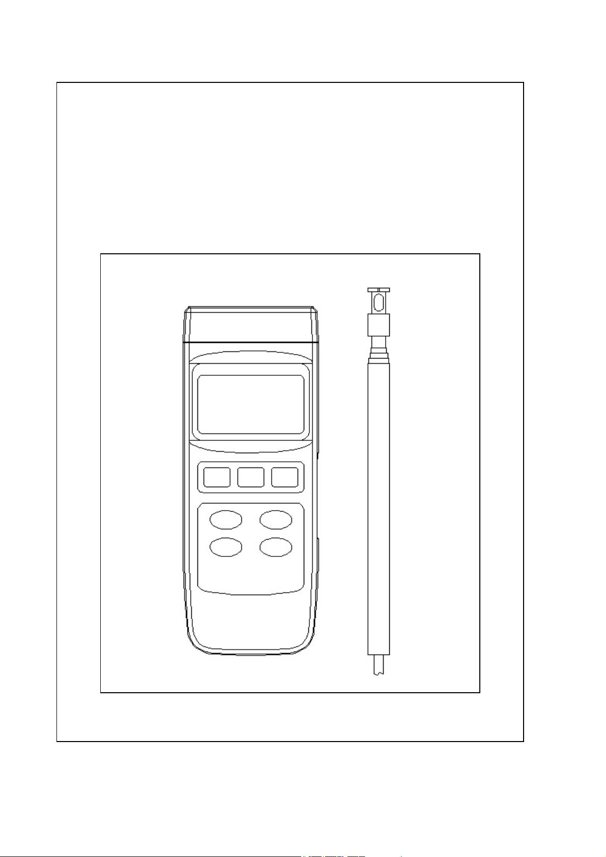
HOT WIRE
ANEMOMETER
Model : HWA2005DL
Page 2

TABLE OF CONTENTS
.
.
.
.
.
.
.
.
.
.
.
1. FEATURES..................................................................1
2. SPECIFICATIONS........................................................2
3. FRONT PANEL DESCRIPTION......................................
4. GENERAL MEASURING PROCEDURE............................
4-1 Air velocity/Air temperature measurement.............. 8
4-2 Air flow ( CMM, CFM ) measurement......................
4-3 Thermocouple ( Type K/J ) Thermometer
measurement....................................................... 12
4-4 Data Hold............................................................. 13
4-5 Data Record (Max., Min. reading)...........................13
4-6 Data Logger..........................................................14
5. ADVANCED ADJUSTMENT PROCEDURE........................ 16
5-1 Check Memory Space............................................
5-2 Clear Memory.......................................................
5-3 Date/Time Setting................................................. 17
5-4 Sample Time Setting.............................................
5-5 Auto Power Off Default Setting..............................
5-6 Temp. Unit Default Setting....................................
5-7 Air Velocity Unit Default Setting.............................
5-8 Air Flow Unit Default Setting.................................. 19
5-9 Area Size ( Air Flow ) Default Setting......................19
5-10 Escape from the SETTING function.......................20
6
8
11
17
17
18
18
18
19
6. HOW TO SEND THE DATA OUT FROM THE METER....... 20
7. RS232 PC SERIAL INTERFACE.....................................
8. BATTERY REPLACEMENT............................................
9. SYSTEM RESET......................................................... 25
10. OPTIONAL ACCESSORIES..........................................26
23
25
Page 3

1. FEATURES
* Combination of hot wire and standard thermistor,
deliver rapid and precise measurements even at low
air velocity value.
* Slim probe, ideal for grilles & diffusers.
* Air velocity : m/S, Ft/min, Km/h, Knot, Mile/h,
* Air flow : CMM ( m^3/min. ) and CFM ( ft^3/min. ).
* Air temperature ( , )℃℉
* Type K/ Type J thermocouple thermometer.
* Real time data logger, build in clock ( hour-min.-sec.,
year-month-date ).
* Auto or manual data record, 16,000 Data logger no.
* Wide sampling time adjustment range from two
seconds to 8 hours 59 minutes 59 seconds.
* Zero adjustment.
* Can default auto power off or manual power off.
* Can default the air velocity, air flow, Temp. unit.
* Air flow measurement can set the area dimension.
* Large LCD with multiple display.
* Data hold, record max. and min. reading.
* Microcomputer circuit provides special function & offer
high accuracy.
* Air Temp. used thermistor sensor, fast response time.
* Power by UM3 ( 1.5 V ) x 4 batteries or DC 9V adapter.
* RS232 computer interface.
* Separate probe, easy for remote measurement.
* Applications : Environmental testing, Air conveyors,
Flow hoods, Clean rooms, Air velocity, Air balancing,
Fans/motors/blowers, Furnace velocity, Refrigerated
case, Paint spray booths.
1
Page 4
2. SPECIFICATIONS
@
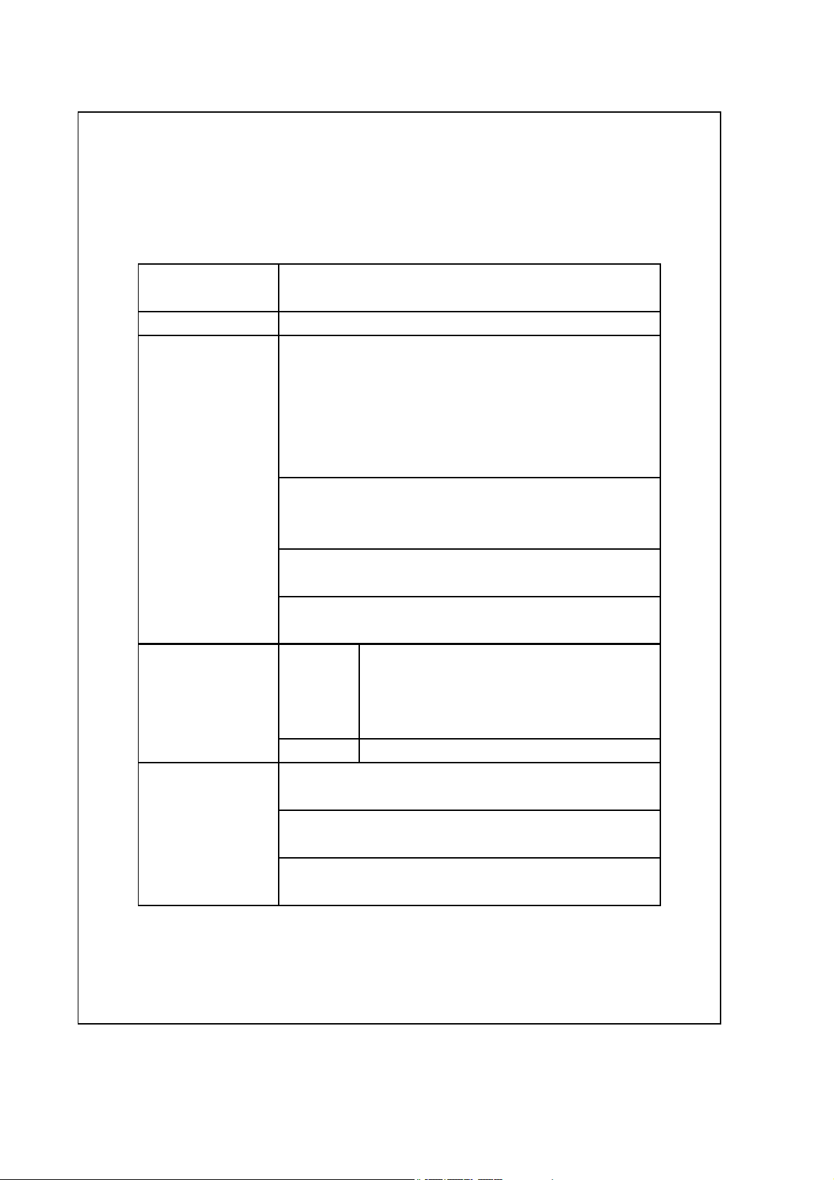
2-1 General Specifications
Circuit Custom one-chip of microprocessor LSI
circuit.
Display LCD size : 58 mm x 34 mm.
Measurement
Unit m/S (meters per second)
Sampling Time Manual Push the data logger button
of Data Logger once will save data one time.
Sensor
Structure Tiny glass bead thermistor.
Air velocity:
Km/h ( kilometers per hour )
Ft/min ( feet per minute )
Knot ( nautical miles per hour )
Mile/h ( miles per hour )
Air flow:
CMM ( m^3/min., cube meter per min. )
CFM ( m^3/min., cube feet per min. )
Air temperature:
, ℃℉
Type K/ Type J thermometer.
, ℃℉
Set the sampling time to
0 second
Auto 2 sec to 8 hour 59 min. 59 sec.
Air velocity & Air flow :
Air temperature :
Thermistor.
Type K/ Type J thermometer.
Thermocouple
2
Page 5
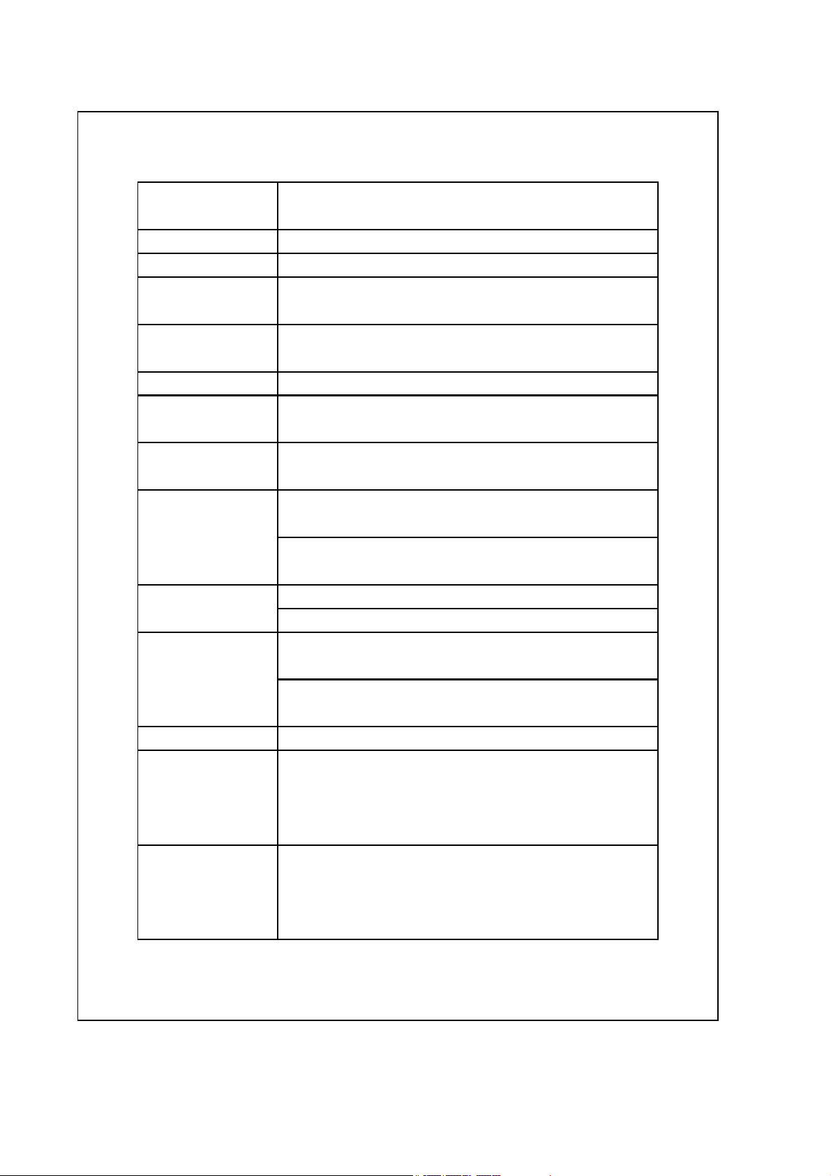
Temperature Automatic temp. compensation for the
Compensation Type K/J thermometer.
Data Hold Freeze the display reading.
Memory Recall Maximum & Minimum value.
Sampling Time Approx. 1 second.
of display
Power off Auto shut off saves battery life or
manual off by push button.
Data Output RS 232 PC serial interface.
Operating 0 to 50 .℃
Temperature
Operating Less than 80% R.H.
Humidity
Power Supply DC 1,5 V battery ( UM3 ) x 4 PCs,
* main instrument
( Heavy duty type ).
DC 9V adapter input.
@ AC/DC power adapter is optional.
Power Supply DC 3V silver battery.
* clock module
Type : CR2032.
Power Current Approx. DC 21.5 mA
@ Main instrument.
Approx. DC 70 mA
@ Main instrument. + Hot wire probe.
Weight 515 g/ 1.13 LB.
Dimension
Main instrument :
@ Battery is included.
203 x 76 x 38 mm
Telescope Probe :
Round, 12 mm Dia x 280 mm ( min. length ).
Round, 12 mm Dia x 940 mm ( max. length ).
Accessories Instruction manual....................... 1 PC
Included Telescope Probe...........................1 PC
DC 3V silver battery, CR2032........ 1 PC
Carrying case............................... 1 PC
3
Page 6
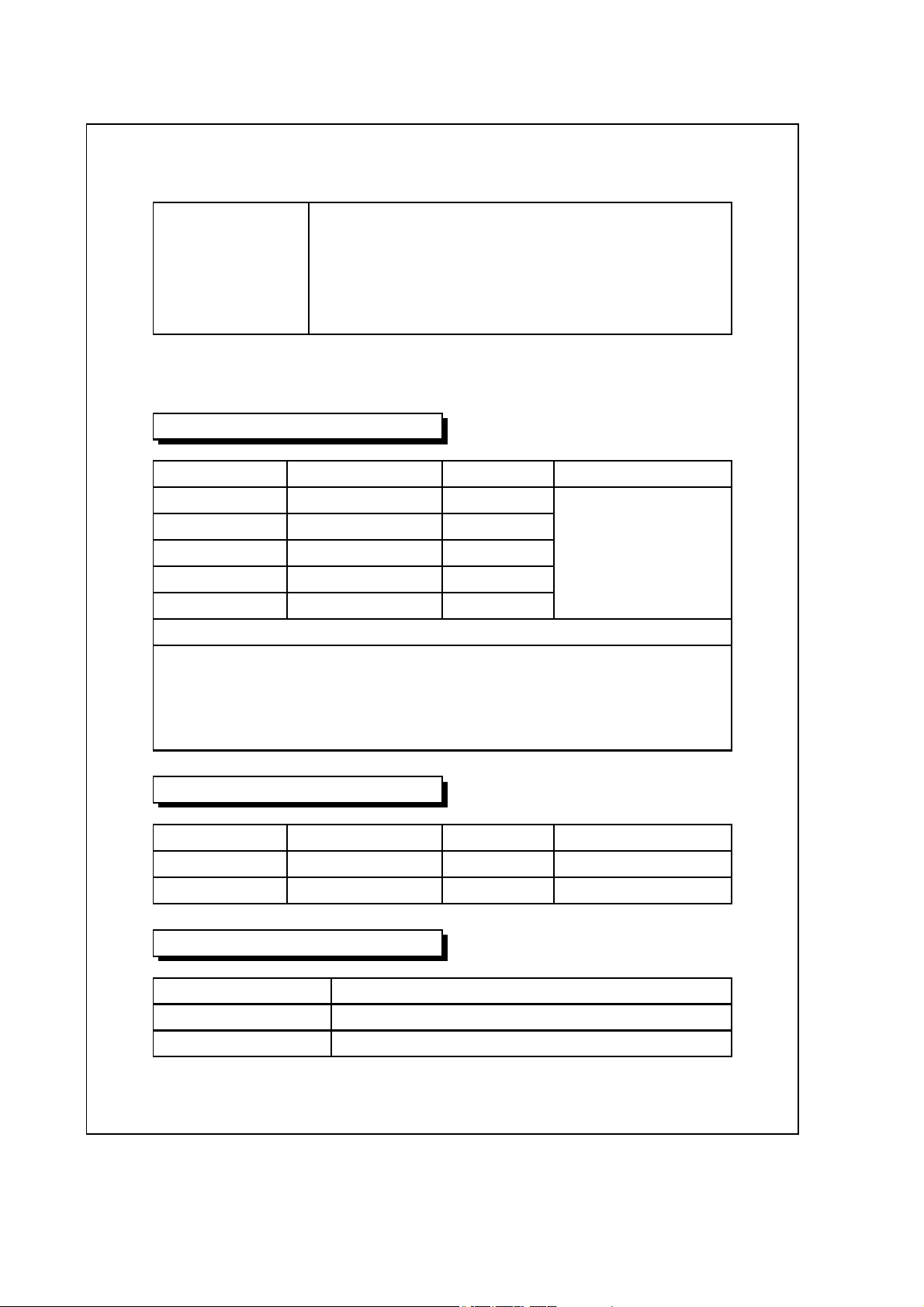
Optional Type K thermocouple probe.
Accessories AC to DC 9V adapter.
RS232 cable, UPCB-02.
Data Acquisition software,SW-U801-WIN.
Data Logger software, SW-DL2005.
2-2 Electrical Specifications (23± 5 )℃
Air velocity
Measurement Range Resolution Accuracy
m/S 0.2 to 20.0 m/s 0.1 m/S ±( 5% + a )
Km/h 0.7-72.0 km/h 0.1 Km/h reading
Mile/h 0.5-44.7 mph 0.1 Mile/h or
Knot 0.4-38.8 knot 0.1 Knot ±( 1% + a )
Ft/min 40-3940 ft/min 1 Ft/min full scale
@ a = 0.1 m/s, 0.1 km/h, 0.1 mile/h, 0.1 knot, 10 ft/min
Note:
m/s - meters per second km/h - kilometers per hour
ft/min - feet/per minute knot - nautical miles per hour
mile/h - miles per hour (international knot)
Air flow
Measurement Range Resolution Area
CMM (m^3/min.) 0 to 36,000 m^3/min. 0.001-1 0.001-30.0 m^3/min.
CFM (ft^3/min.). 0 to 1,271,200 ft^3/min. 0.01-100 0.01-322.91 ft^3/min.
Air temperature
Measuring Range 0 to 50 /32 to 122 ℃℃℉ ℉
Resolution 0.1 /0.1 ℃℉
Accuracy ± 0.8 /1.5 ℃℉
4
Page 7
Type K/J thermometer
@
Sensor Reso- Range Accuracy
Type lution
Type K 0.1 ℃ -50.0 to 1300.0 ℃ ± ( 0.2 % + 0.5 )℃
-50.1 to -100.0 ℃ ± ( 0.2 % + 1 )℃
0.1 ℉ -58.0 to 2372.0 ℉ ± ( 0.2 % + 1 )℉
-58.1 to -148.0 ℉ ± ( 0.2 % + 1.8 )℉
Type J 0.1 ℃ -100.0 to 1100.0 ℃ ± ( 0.2 % + 0.5 )℃
-50.1 to -100.0 ℃ ± ( 0.2 % + 1 )℃
0.1 ℉ -58.0 to 2012.0 ℉ ± ( 0.2 % + 1 )℉
-58.1 to -148.0 ℉ ± ( 0.2 % + 1.8 )℉
Above specification tests under the environment RF
Field Strength less than 3 V/M & frequency less than
30 MHz only.
5
Page 8
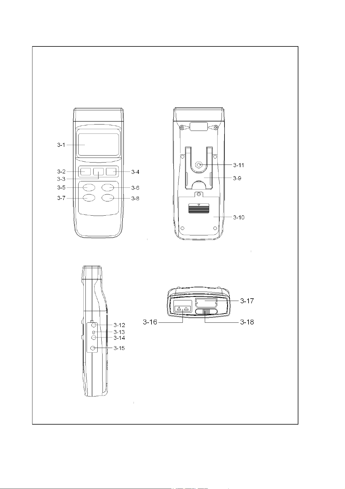
3. FRONT PANEL DESCRIPTION
Fig. 1
6
Page 9
3-1 Display
3-2 Power Button
3-3 HOLD Button ( ESC Button )
3-4 REC Button ( Enter Button )
3-5 Up Button ▲
3-6 Function Button ( Down Button )▼
3-7 Send Button ( Clock Button )
3-8 SET Button ( Logger Button )
3-9 Stand
3-10 Battery Compartment/Cover
3-11 Tripod Fix Nut
3-12 LCD Brightness Adjust VR
3-13 System Reset Switch
3-14 RS-232 Output Terminal
3-15 DC 9V Power Adapter Input Socket
3-16 Type K/J Probe Input Socket
3-17 Probe Input Socket
3-18 Probe Lock Switch ( System On/Off Switch )
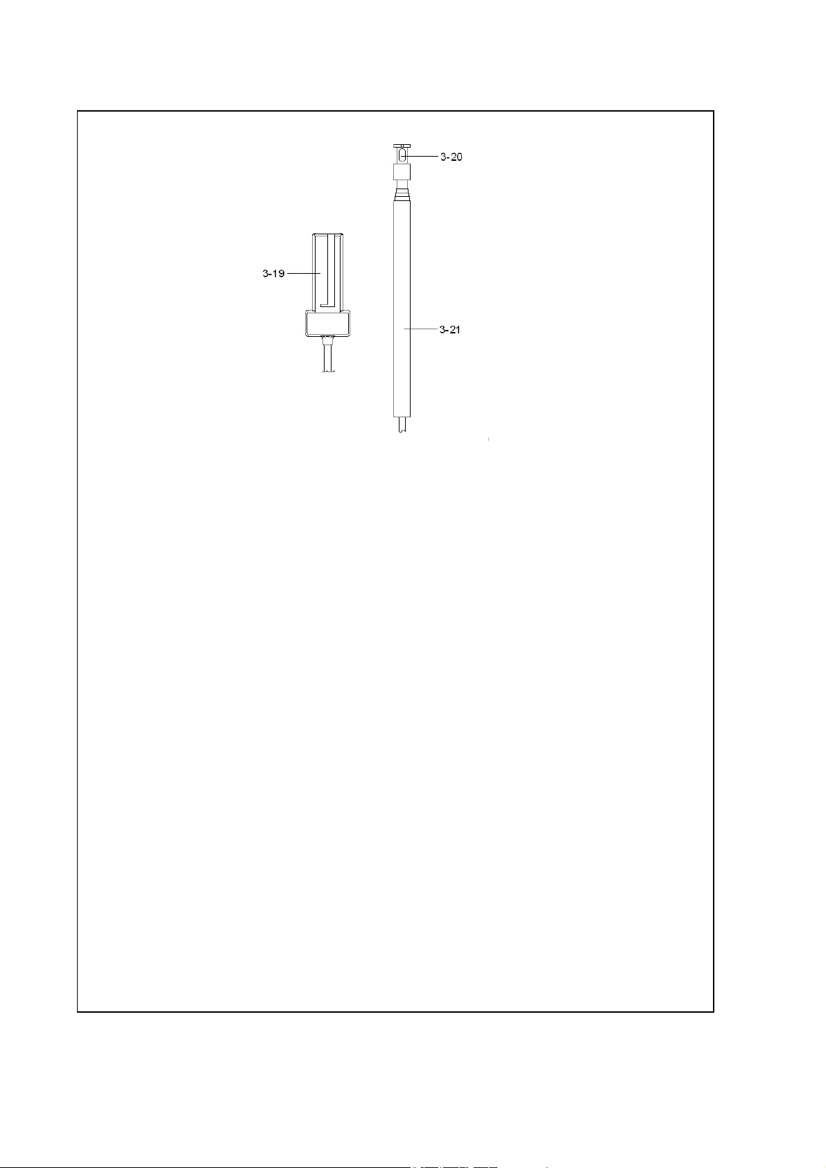
3-19 Probe Plug
3-20 Sensing Head
3-21 Telescope Probe
Fig. 1
7
Page 10

4. GENERAL MEASURING
PROCEDURE
The meter default value are following :
* The air velocity unit is m/S.
* The temperature unit is .℃
* The air flow unit is CMM.
* The air flow area is meter^2 ( meter square ).
* The sampling time of data logger function is
2 seconds.
4-1 Air velocity /Air Temp. measurement
1)Important information of using the Telescope Probe
*
When the probe is not used, the " Sensor cover "
should slide to the up position.
When the probe is not used, the
" Sensor cover " should slide to the
up position.
Probe Handle
Fig. 2
8
Page 11

*
When begin to use the probe,
a. Slide the sensor cover to the down position, let the
air velocity sensor to contact the air, refer Fig. 3.
b. Extent the telescope probe to the convenient length
,refer Fig. 3
air velocity sensor
( do not touch by
fingers or tools )
" Sensor cover "
slide to the low
position when
make the
measurement
Probe Handle
Fig. 3
*
Do not use the fingers or any tools to touch the air
velocity sensor, otherwise the meter may happen
the permanent damage without warranty.
*
Direction of the sensor head :
There is a mark on the top of the " Sensor Head ",
When make the measurement, then this mark should
against the measured wind, refer Fig. 4.
9
Page 12

When sensor head face against the measurement air,
then the upper display will show the air velocity value.
The lower display will show the temperature value.
Direction mark should face
the measured wind.
sensor head ( side view )
Fig. 4
Probe Handle
2)Install the " Probe Plug " ( 3-19, Fig. 1 ) into the
" Probe Input Socket " ( 3-17, Fig. 1 ).
Attention :
After install the " Probe Plug ", should slide
Probe Lock Switch " ( 3-18, Fig. 1 ) to the On
position ( right position ).
3)Power on the meter by pressing the " Power Button "
( 3-2, Fig. 1 ).
4)Select measuring function by pressing " Function
Button " ( 3-6, Fig. 1 ) until the display show the
air velocity unit.
@ Air velocity measurement, the display unit
will show m/S ( or Ft/min, Km/h, Knot, Mile/h ).
@ The Air velocity unit adjustment, please refer
Chapter 5-7.
10
Page 13

5)Hold the " Probe Handle " ( 3-21, fig. 1 ) by hand
& let the " Sensor Head's mark " ( 3-20, Fig. 1 ) face
against the measuring air flow source, then the
Display ( 3-1, Fig. 1 ) will show air velocity directly. At
the same time, the display will show the air
temperature value.
@ The Temp. unit adjustment, please refer Chapter 5-6.
Measuring Consideration :
The mark on the sensor head indicates the
direction that " need to face against the air
flow.
4-2 Air flow ( CMM, CFM ) measurement
1)Install the " Probe Plug " ( 3-19, Fig. 1 ) into the
" Probe Input Socket " ( 3-17, Fig. 1 ).
Attention :
After install the " Probe Plug ", should slide
Probe Lock Switch " ( 3-18, Fig. 1 ) to the On
position ( right position )
2)Power on the meter by pressing the " Power Button "
( 3-2, Fig. 1 ).
3)Select measuring function by pressing " Function
Button " ( 3-6, Fig. 1 ) until the display show the
air flow unit ( CMM or CFM ).
@ Air flow measurement, the display unit
will show CMM ( or CFM ).
@ CMM : cube meter per minute.
CFM : cube feet per minute.
@ The air flow unit adjustment, please refer Chapter 5-8.
11
Page 14

4)The display's bottom left side will show area size in
.
Meter^2 ( or Ft^2 ) when make the air flow measurement.
@ Meter^2 : Meter square, Ft^2 : Feet square.
@ The adjusting procedures of area size, please refer
Chapter 5-9.
5)Hold the " Telescope Probe " ( 3-21, fig. 1 ) by hand &
let the " Sensing Head " ( 3-20, Fig. 1 ) face against to
the measuring air flow source, then the Display ( 3-1,
Fig. 1 ) will show air flow value.
Measuring Consideration :
Sensor head direction
The mark on the sensor head indicates the
direction that " need to face against the air flow.
Zero setting :
a.When slide the sensor cover of " Sensing
Head " ( 3-20, Fig. 1 ) to the up position
to let the air velocity sensor isolated
from the environment ( refer Fig. 2 ).
b
Push the " Button " ( 3-5, Fig. 1 ) 2 seconds▲
continuously at least to let the reading value
of air velocity show zero value.
4-3 Thermocouple ( Type K/J ) Thermometer
measurement
1)Not install the anemometer " Probe Plug " ( 3-19,
Fig. 1 ) into the " Probe Input Socket " ( 3-17, Fig. 1 )
Attention : After take away the anemometer
Probe Plug " , then should slide Probe
Lock Switch " ( 3-18, Fig. 1 ) to the On
position ( right position )
12
Page 15

2)Plug the Thermocouple Temp. Probe ( Type K Temp.
probe pr Type J Temp. probe, optional ) into " Type
K/J Probe Input Socket " ( 3-16, Fig. 1 )
3)Power on the meter by pressing the " Power Button "
( 3-2, Fig. 1 ).
4)For the Type K Probe, press the " Function Button "
( 3-6, Fig. 1 ) to let the bottom right LCD show the
" K type " indicator
For the Type J Probe, press the " Function Button "
( 3-6, Fig. 1 ) to let the bottom right LCD show the
" J type " indicator
4-4 Data Hold
During the measurement, press the " Hold Button " ( 3-3,
Fig. 1 ) once will hold the measured value & the LCD will
display a " HOLD " symbol.
* Press the " Hold Button " once again will release the data
hold function.
4-5 Data Record ( Max., Min. reading )
* The data record function records the maximum and
minimum readings. Press the " REC Button " ( 3-4, Fig.
1 ) once to start the Data Record function and there
will be a " REC. " symbol on the display.
* With the " REC. " symbol on the display :
a)Press the " REC Button " ( 3-4, Fig. 1 ) once, the "
REC. MAX. " symbol along with the maximum value
will appear on the display.
If intend to delete the maximum value, just press
the " Hold Button " ( 3-3, Fig. 1 ) once, then the
display will show the " REC. " symbol only & execute
the memory function continuously.
13
Page 16

b)Press the " REC Button " ( 3-4, Fig. 1 ) again, the
" REC. MIN. " symbol along with the minimum value
will appear on the display.
If intend to delete the minimum value, just press
the " Hold Button " ( 3-3, Fig. 1 ) once, then
the display will show the " REC. " symbol only &
execute the memory function continuously.
c) To exit the memory record function, just press the
" REC " button for 2 seconds at least. The display will
revert to the current reading.
4-6 Data Logger
The data logger function can save 16,000 measuring
data with the clock time ( Real time data logger, build
in clock ( hour-min.-sec., year-month-date ).
The data logger procedures are as following :
a)If push the Logger Button " ( 3-8, Fig. 1 ) once will
show the sampling time value on the bottom left
display then disappeared.
b)Press the " REC Button " ( 3-4, Fig. 1 ) once to
start the Data Record function and there will be a
" REC. " symbol on the display.
c) Auto Data Logger ( Sampling time set from
2 seconds to 8 hours 59 minutes 59 seconds )
Press the " Logger Button " ( 3-8, Fig. 1 ) once to start
the Auto Data Logger function, at the same the
bottom right display will show the indicator "
Recording.... ", now the Data Logger function is
executed. The upper display will show DATA "
indicator along with " REC " marker.
14
Page 17

d)Manual Data Logger ( Sampling time set to 0
second )
Press the " Logger Button " ( 3-8, Fig. 1 ) once will
save the data one time into the memory, at the same
time the bottom right display will show the indicator
" Recording.... " a while. Now the Data logger function is
executed. The upper display will show " DATA "
indicator along with " REC " marker.
e) Memory full
Under execute the data logger, if the bottom right
display show the " Full ", it indicate the memory data
already over 16,000 no. and the memory is full.
f) During the Data Logger function is executed, press the "
Logger Button " ( 3-8, Fig. 1 ) once will stop to execute
the data logger function, the " DATA " indicator
will be disappeared.
If press the " Logger Button " ( 3-8, Fig. 1 ) once again
will continuous the Data Logger function.
Remark :
1)
If intend to change the data logger sampling time,
please refer chapter 5-4.
2)
If intend to know the space of balance data numbers
into the memory IC, please refer chapter 5-1.
3)
If intend to clear the saving data from the memory
please refer chapter 5-2.
15
Page 18

5. ADVANCED ADJUSTMENT
PROCEDURES
When execute the following Advanced
Adjustment Procedures should cancel the " Hold
function " and the " Record function " first. The
display will not show the " HOLD " and the " REC "
marker.
a. Press the " SET Button " ( 3-8, Fig. 1 ) at least two
seconds until the lower display show
XXXXX Memory Space
* If push the " ESC Button " ( 3-3, Fig. 1 ) will escape
the selecting function and return to the normal
measuring display.
b. One by one to press the " Set Button " ( 3-8, Fig. 1 )
once a while to select the ten main function, at the
same time lower display will show on the lower
display will show on the lower display as :
Memory Space
Clear Memory
Date/Time Set
Sample Time
Auto Power Off
Temp. Unit
Default Vel.
Default FLOW
Area
ESC Finish→
16
Page 19

c. When make Advanced Adjustment Procedure
will use the following key buttons :
ESC Button ( 3-3, Fig. 1 ), Enter Button ( 3-4, Fig. 1 )
Up Button ( 3-5, Fig. 1 ), Down Button ( 3-6, Fig. 1 )▲▼
SET Button ( 3-8, Fig. 1 ), SEND Button ( 3-7, Fig. 1 )
5-1 Check Memory Space
To check the balance data numbers that exist into the
memory ( allow memorize data no. ).
XXXXX Memory Space
@XXXXX is the balance data numbers, for example
XXXXX=15417.
5-2 Clear Memory
* To delete the existing save data numbers from the
memory.
* Push ENTER Button once, then push ENTER Button
to confirm.
* Press the ESC Button once to quite and return to
the main measurement manual.
5-3 Date/Time Setting
* Use Up Button, Down Button and ▲▼
Enter ( ) Button to select the expect Date →
( year-month-date ) and the time (HOUR-MIN.-SEC.).
* After finish the Date/Time adjustment,
Push the " Enter Button " , then press the " ESC Button "
will quite and save the clock data into the memory.
17
Page 20

5-4 Sample Time Setting
* Use Up Button, Down Button and Enter ( ) ▲▼ →
Button to select the expect Sample Time ( HOUR-MIN.-SEC.).
* After finish the Sample Time adjustment,
Push the " Enter Button " , then press the " ESC Button "
will quite and save the clock data into the memory.
5-5 Auto Power Off Default Setting
* Use Up Button, Down Button to select " 1 " or ▲▼
" 0 ".
1 = Auto power On.
0 = Auto power Off.
* After finish the Auto Power Off adjustment,
push the " Enter Button " , then press the " ESC Button "
will quite and return to the normal measurement
display.
5-6 Temp. Unit Default Setting
* Use Up Button, Down Button to select " 1 " or ▲▼
" 0 ".
1 = ℉
0 = ℃
* After finish the Temperature unit adjustment,
push the " Enter Button " , then press the " ESC Button "
will quite and return to the normal measurement
display.
18
Page 21

5-7 Air Velocity Unit Default Setting
* Use Up Button, Down Button to select the▲▼
default Air Velocity unit as :
m/S, Ft/min, Km/h, Knot, Mile/h,
* After finish the Air Velocity unit adjustment,
push the " Enter Button " , then press the " ESC Button "
will quite and return to the normal measurement
display.
5-8 Air Flow Unit Default Setting
* Use Up Button, Down Button to select the▲▼
default Air Flow unit as : CMM or CFM
CMM : cube meter per minute.
CFM : cube feet per minute.
* After finish the Air Flow unit adjustment, push the "
Enter Button " first, then press the " ESC Button " again
will quite and return to the normal measurement display.
5-9 Area Size ( Air Flow ) Default Setting
* Use Up Button, Down Button and the SEND ( )▲▼ →
to select the desired area value.
@If the 5-8 select the CMM, the area unit is
Meter^2 ( Meter square ) and the adjustment range
is limited to 0.001 to 30.000 Meter square.
@If the 5-8 select the CFM, the area unit is
Feet^2 ( Feet square ) and the adjustment range
is limited to 0.01 to 322.92 Feet square.
* After finish the Area Size adjustment, push the
" Enter Button " first, then press the " ESC Button " again
will quite and return to the normal measurement display.
19
Page 22

5-10 Escape from the SETTING function
Press the " ESC Button " once a while will quite and
return to the normal measurement display.
6. HOW TO SEND THE DATA OUT
FROM THE METER
1)If intend to send the data out from the meter, it
should cancel the " Hold function " and the " Record
function " first. The display will not show the " HOLD "
and the " REC " marker.
2)Press the " SEND Button " ( 3-7, Fig. 1 ) at least 2
seconds until the bottom right display show " Transmit
mode ", then release the button.
LCD display will show the fowling screen
alternately.
0.3 1
m/S ← m/S
→
1 Transmit mode xx:xx:xx Transmit mode
Block no. The first Start time Start data
data of of each address of
each block block each block
Use Up Button, Down Button to select the▲▼
different data memory block no. ( 1 to 250 ).
20
Page 23

The meter can save 16,000 data max. , those
data will saved into 250 memory block max.
* One " Memory Block " means :
The data that save into one routine Data Logger
procedures ( Push " REC " button , following push
the " Logger " button to save the data, the display
will show the " REC " and " DATA " . After save the
data push the " Logger " button, following push
the " REC " button, will exist the Data Logger
function. The " REC " and " DATA " indicator of LCD
will be disappeared ). Please refer Chapter 4-6,
page 14.
Block 1 Data 1
to
Data X
↓
Block 2 Data X+1
to
Data Y
↓
..................
..................
↓
Block 250 Data Z
to
Data 16,000
21
Page 24

3)Until the desired Memory Block no. be selected.
@
@
Push the " Send Button " ( 3-5, Fig. 1 ) once, the
data in the Memory Block will send out.
During the data send out, the bottom right display will
show the " Sending Data ! " indicator. When data
already send out completely, the bottom right display
will show the Transmit mode " indicator again.
5)Push the " ESC Button " ( 3-3, Fig. 1 ) will exist
the data sending function and return to the normal
display.
Remarks :
If intend up load the data to the computer,
then should connect the RS232 cable
( optional, model : UPCB-02) and apply the
Data Logger software ( optional, Model :
SW-DL2005 ).
When sending the data, each time just can
send one Memory Block data out. for example
block 1 data, block 2 data... or block 250 data.
22
Page 25

7. RS232 PC SERIAL INTERFACE
.
The instrument has RS232 PC serial interface via a 3.5
mm terminal ( 3-14, Fig. 1 ).
The data output is a 16 digit stream which can be
utilized for user's specific application.
A RS232 lead with the following connection will be
required to link the instrument with the PC serial port.
Meter PC
(3.5 mm jack plug) (9W 'D" Connector)
Center Pin..........................Pin 4
Ground/shield......................
The 16 digits data stream will be displayed in the
following format :
D15 D14 D13 D12 D11 D10 D9 D8 D7 D6 D5 D4 D3 D2 D1 D0
Pin 2
2.2 K
resister
Pin 5
23
Page 26

Each digit indicates the following status :
D0 End Word = 0D
D1 & D8 Display reading, D1 = LSD, D8 = MSD
For example :
If the display reading is 1234, then D8 to
D1 is : 00001234
D9 Decimal Point(DP), position from right to the
left
0 = No DP, 1= 1 DP, 2 = 2 DP, 3 = 3 DP
D10 Polarity
0 = Positive 1 = Negative
D11 & Annunciator for Display
D12 = 01 ℃ Knot = 09 mile/h = 12
= 02℉ Km/h = 10 CMM = 84
m/S = 08 ft/min = 11 CFM = 85
D13 When send the upper display data = 1
When send the lower display data = 2
D14 4
D15 Start Word = 02
RS232 setting
Baud rate 9600
Parity No parity
Data bit no. 8 Data bits
Stop bit 1 Stop bit
24
Page 27

8. BATTERY REPLACEMENT
When the left corner of LCD display show " ", it
1)The time to change the UM3 ( 1.5 V ) x 4 PCs
is necessary to replace the batteries ( UM3/1.5 V x 4 PCs ).
The time to change the CR2032 ( 3V silver battery )
When the clock is not accurate or power off the meter
then on, the clock time is disappeared or garbled, it is
necessary to replace the battery ( CR2032 )
2)Slide the " Battery Cover " ( 3-10, Fig. 1 ) away from the
instrument and remove the battery.
3)Replace with batteries ( UM3/1.5 V x 4 PCs or CR2032 )
and reinstate the cover.
4)Make sure the battery cover is secured after changing
the battery.
9. SYSTEM RESET
If the meter happen the troubles such as :
CPU system is hold ( for example, the key button can
not be operated... ).
Then make the system RESET will fix the problem.
The system RESET procedures will be either following
method :
25
Page 28

1)Slide the " Probe Lock Switch/System On/Off
Switch " from the On to Off, then On again.
2)Or during the Power On, used a pin tool to push
the " System Reset Switch " ( 3-13, Fig. 1 ) once
a while.
10. OPTIONAL ACCESSORIES
RS232 cable * Isolated RS232 cable.
UPCB-02 * Used to connect the meter to
the computer
Data Logger * Software the used to download
software the data logger ( data recorder )
SW-DL2005 from the meter to computer.
Data Acquisition * The SW-U801-WIN is a multi
software displays ( 1/2/4/6/8 displays )
SW-U801-WIN powerful application software,
provides the functions of data
logging system, text display,
angular display, chart display,
data recorder high/low limit, data
query, text report, chart report..
.xxx.mdb data file can be
retrieved for EXCEL, ACESS..,
wide intelligent applications.
26
Page 29

Thermocouple * Measure Rage: -40 to 250 , ℃℃
Probe -40 to 482 .℉℉
(Type K) TP-01 * Max. short-tern operating
Temperature: 300 (572 ).℃℉
* It is an ultra fast response
naked-bead thermocouple
suitable for many general purpose
application.
Thermocouple * Measure Range: -50 to 900 ,℃℃
Probe -50 to 1650 .℉℉
(Type K), TP-02A * Dimension:10cm tube, 3.2mm Dia.
Thermocouple * Measure Range: -50 to 1200 ,℃℃
Probe -50 to 2200 .℉℉
(Type K), TP-03 * Dimension: 10cm tube, 8mm Dia.
Surface Probe * Measure Range: -50 to 400 ,℃℃
(Type K), TP-04 -50 to 752 .℉℉
* Size :
Temp. sensing head - 15 mm Dia.
Probe length - 120 mm.
27
0501-HWA2005DL
 Loading...