

Page 1
THERMAL IMAGING
AND
THERMAL/VISUAL
IMAGING CAMERAS
CAMERA
GTi10
GTi20, GTi30,
GTi50
T
USER’S MANUAL
G
G
G
Please read this manual carefully and thoroughly before using this product.
1
Page 2

ging
Sectional Overview
What you should know and do to ensure your safety
and avoid dama
the camera
Read This
First
Illustrations and descriptions of all camera
components and connectors
Product
Overview
How to charge the battery pack; install the mini SD
memory card; power the camera on and off; set the
date and time; and select a language, TV standard
and measurement unit
Setup
Instructions
How to read the display; navigate menus; restore
default settings
Basic
Functions
How to make camera adjustments such as:
• Manual focusing
• Fusing thermal and visual images
• Moving fusion squares and choosing a
palette
• Adjusting camera parameters and image
settings
• Saving and freezing/activating images
Shooting
• Using analysis tools and changing analysis
settings
• Working with spots, areas, profiles and
isotherms
• Voice-annotating images
• Defining trigger functions
Locating, viewing and erasing saved images;
playing back voice memos.
Playback and
Erase
How to: upload images to a computer; charge the
battery directly, connect to a TV monitor or PC; use
the Bluetooth headset
2
Camera
Connections
Page 3

Table of Contents
Read This First 5
What’s Included 7
Product Overview 8
Front View
Keypad & Bottom View 9
Setup Instructions 10
Charging the Battery Pack 10
Installing the Battery Pack and Mini SD Card 11
Powering On and Off 12
Reading the Display 13
Setting the Date and Time 15
Local Settings 16
Basic Functions 18
Selecting Menus and Settings
Restoring Default Settings
Shooting
Using the LCD
Making Camera Adjustments 22
Manual Focus
Thermal, Visual and BiVision Image Displays 23
BiVision Display Mode
Making Image Adjustments 26
Auto Adjust
Making Manual Adjustments 27
Palette Settings
Image/camera Settings
Freezing/Activating an Image 31
Using Analysis Tools 32
Changing Object/Global Settings 32
Setting Analysis Parameters 34
Setting Spot Analysis Parameters 36
Setting Area Analysis Parameters 38
Profile Analysis 40
Isotherm Analysis 41
Removing Analysis Tools 42
Saving Images 43
Attaching Voice Memos to Images 45
Voice Recording 45
Configuring the Trigger
Playback and Erase 47
Opening Images 47
Playing Back Voice Memos 50
Erasing Images 51
Uploading Images 52
Camera Connections 53
Charging the Battery Directly
Connecting to a TV Monitor 54
3
8
18
20
21
21
22
24
26
28
29
46
53
Page 4

Connecting to a Computer
g
Using the Bluetooth Headset 56
Troubleshootin
58
55
Appendices 59
I. Using an Optional Lens 59
II. Camera Care and Maintenance 60
III. The Emissivity of Common Materials 61
Specifications 65
Warranty Information 66
Return for Repair Policy 66
4
Page 5

Read This First
Practice Makes Perfect
Before attempting to shoot important subjects, shoot several t ri al images to confirm that the thermal
camera is operating correctly and that you know how to operate it correctly.
General Tools & Instruments LLC (General) and its subsidiaries, affiliates and distributors are not
liable for any consequential damages arising from any malfunction of the camera or any accessory
that results in the failure of an image to be recorded or to be recorded in a format that is
machine-readable.
Safety Precautions
Before using the camera, read and understand t he safety and precauti ons descri bed in this section.
They are intended to help you operate the therma l camer a and its accessories without 1) risking
injuries to yourself and others or 2) damaging the camera itself.
Avoid damaging eyesight
Warning: Do not aim the laser pointer at any person or animal.
Prolonged exposure may damage eyesight.
Do not disassemble
Do not attempt to disassemble or modify any part of the camera or its accessories.
Stop operating immediately if the camera is dropped, the casing is damaged, or the
camera emits smoke or noxious fumes
Failure to do so may result in fire or electrical shock. Immediately turn the thermal camera’s pow er off,
remove the battery or unplug the power cord from the power outlet.
Do not use substances containing alcohol, benzene, thinners or other flammable
substances to clean or maintain the thermal camera
The use of these substances may start a fire.
Remove the power cord on a regular periodic basis and wipe away the dust and dirt that
collects on the plug, the exterior of the power outlet and the surrounding area
In dusty, humid or greasy environments, the dust that collects around the plug over long periods of time
may become saturated by humidity and short-circuit, leading to fire.
Do not handle the power cord if your hands are wet
Handling the cord with wet hands may lead to electrical shock. When unplugging the cord, pull on the
plug, rather than the cord. Pulling on the cord may damage or expose wires and insulation, creating the
potential for fires and electric shocks.
Do not cut, alter or place heavy items on the power cord
Any of these actions may cause an short circuit than can lead to fire or electrical shock.
Use only recommended power accessories
Use of power sources not expressly recommended for this thermal camera may lead to overheating,
5
Page 6

distortion of the thermal camera, fire, electrical shock or other hazards.
y
Do not drop the batteries, place them near a heat source, directly expose them to flame, or
immerse them in water
Such exposure may damage the batteries and lead to leakage of corrosive liquids, fire, electric shock,
explosion or serious injury.
Do not attempt to disassemble, modify or apply heat to the batteries
Any of the actions may cause an explosion. If any part of your body comes into contact with battery acid
in any form, immediately flush that area with water If your mouth or eyes are involved, immediately flush
with water and seek medical assistance.
Do not short-circuit the battery terminals with metallic objects, such as keys
Doing so could lead to overheating, burns and other injuries.
Before you discard a battery, cover the terminals with tape or other insulators to prevent
direct contact with other objects
Contact with the metallic components of other materials in waste containers may lead to fire or
explosions. Discard the batteries in specialized waste facilities if available in your area.
Use only recommended batteries and accessories
Use of batteries not expressly recommended for this equipment may cause explosions or leaks,
resulting in fire, injury and damage to the surroundings.
Disconnect the compact power adapter from both the thermal camera and power outlet
after recharging and when the thermal camera is not in use
Continuous use over a long period of time may cause the unit to overheat, creating a fire risk.
Exercise caution when detaching or attaching a lens
If the lens falls and breaks as it comes loose, the glass shards may cause an injury.
Use of the camera for prolonged periods may cause its body to become warm
Such heating is normal, and should be considered a minor burn risk
Preventing Damage to the Camera
Avoid damaging the IR detector
Warning: Do not aim the thermal camera directly at the sun or a
source of intense heat (such as an arc welder). Doing so for more
than a few seconds will permanently damage the camera’s IR
detector and void the camera’s limited warrant
Avoid Condensation Related Problems
Moving the thermal camera rapidly between hot and cold environments may cause condensation
(water droplets) to collect on its external and internal surfaces.
If condensation appears, stop using the camera immediately and power it off. If charging the
battery directly, detach the charger from the unit. Then remove the battery and wait until the condensate
evaporates completely before resuming use.
To minimize condensation: 1) store the camera in its protective case when not in use, and 2) give the
camera time to adjust to its new surroundings before using it.
Extended Storage
When you do not expect to use the thermal camera for even a few weeks, remove batteries from the
camera and the compact battery charger, place the camera in its case and store the case in a safe place.
Storing the camera or the compact charger for a long time with a battery inside will completely discharge
the battery, creating a risk of damaging leakage.
.
6
Page 7

What’s Included
Item
Thermal camera
Heavy-duty plastic protective case
Compact
Rechargeable battery (1 installed in camera, 1 in c a s e )
2GB Mini SD memory card
battery cha
with
shoulder strap
rger
with adaptor (pre-installed in camera)
Quantity
1
1
1
2
1
Sun shield
Video cable
USB cable
Hand and neck
Lens cap
CD containing: Reporting and analysis software (standard
manual; Camera
Hard copy of calibration certificate
Hard copy of QuickStart guide
Hard copy of packing list
with
BNC plug
straps (on camera)
user’s
manual; QuickStart guide, Warranty card
version); Software user’s
1
1
1
1
1
1
1
1
1
Hard copy of warranty card
Bluetooth headset and charger (GTi30 and GTi50 only)
7
1
1
Page 8
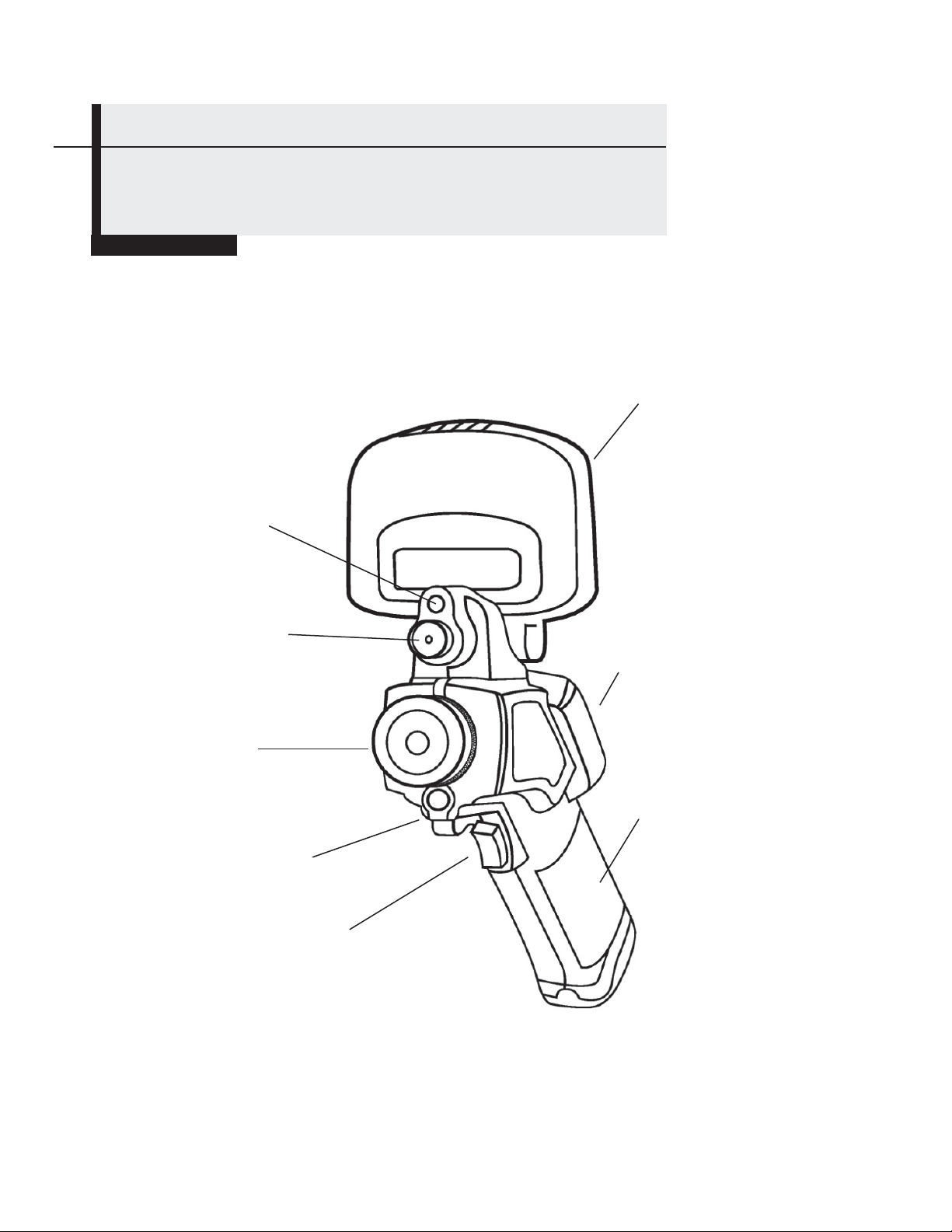
Product Overview
Front View
Torch (Flashlight)
(GTi20 , GTi30 and GTi50 only)
Visual camera
(GTi20 , GTi30 and GTi50 only)
Flip-up LCD
Keypad
IR camera
and lens
Battery compartment
Laser pointer
Definable trigger
8
Page 9
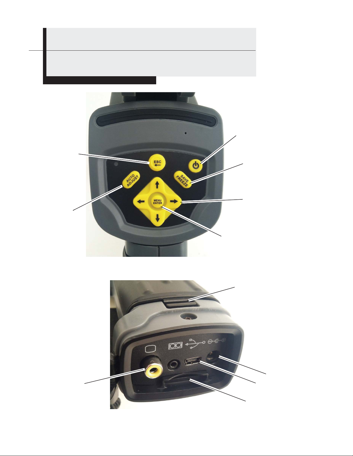
Product Overview
Keypad and Bottom Views
Menu up 1
level and
Escape
Auto Adjust
Power Button
Save/Freeze
screen and images
Menu Navigati on - Toggle
Up, Dow n , Left, Right
Video Out jack
Menu Access,
Enter to choose selection
Battery compartment latch
Power input jack
Mini USB jack
Mini SD card slot
9
Page 10
i
Setup Instructions
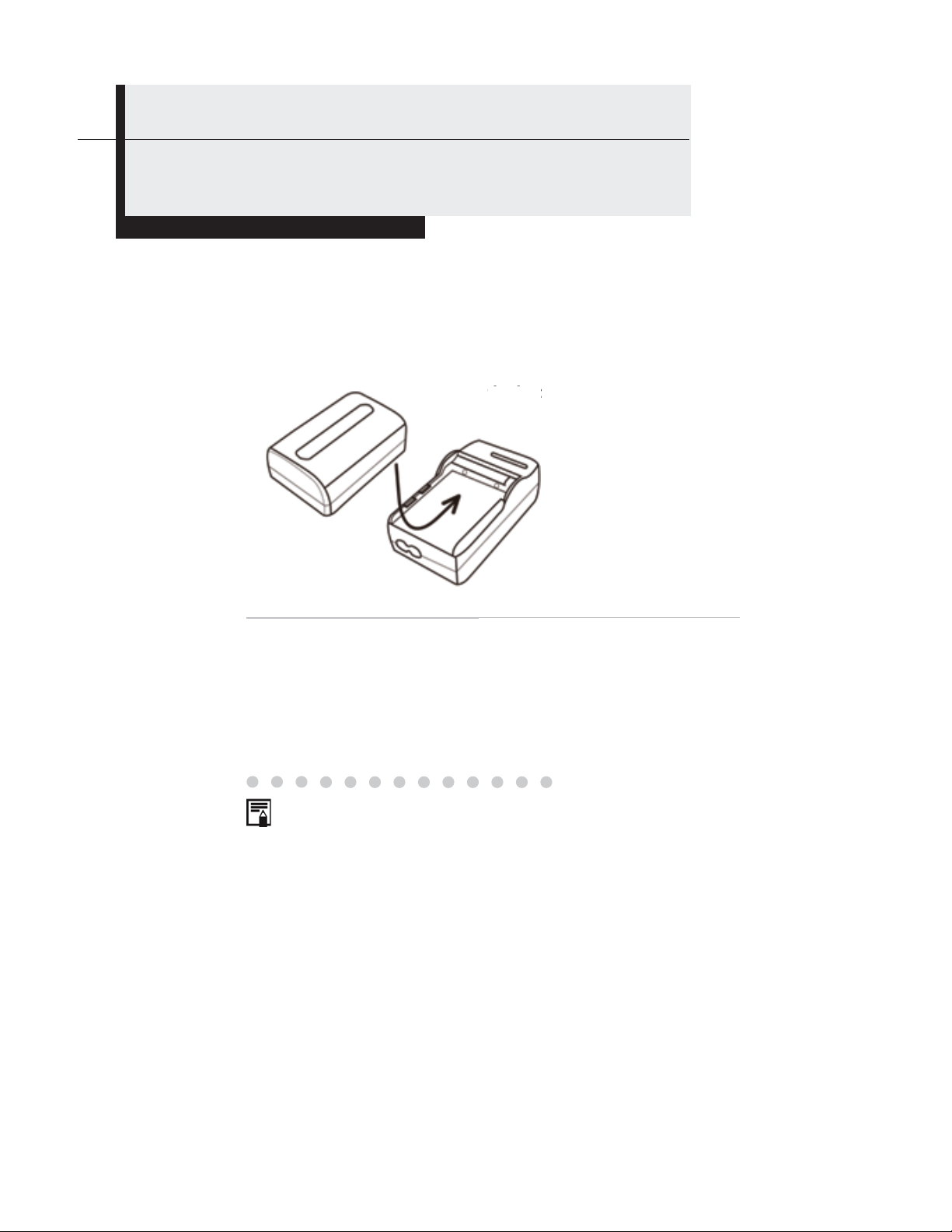
Charging the Battery
Use the following procedures to charge the battery pack for the first time and
subsequently when the low battery icon appears on the LCD.
1
Position a battery in the
compact battery charger so the
contacts nearly touch. Push
the bat
the battery forward until it
snaps
snaps into place.
Plug one end of the power cord into the charger and the other end
2
into a 110VAC outlet.
The light on the charg e r will glow red while the battery is
•
charging. It will turn green when charging is complete.
After charging, unplug the battery charger and remove
•
the charged battery.
•
This is a lithium ion battery pack so there is no need to
discharge it completely before recharging. It can be recharged
at any time. However, since the maximum number of charge
cycles is approximately 300, to prolong battery life General
recommends that you only charge the battery pack after it has
been discharged completely.
Charging times will vary according to the surrounding
•
humidity and battery pack charge state.
10
Page 11
Setup Instructions
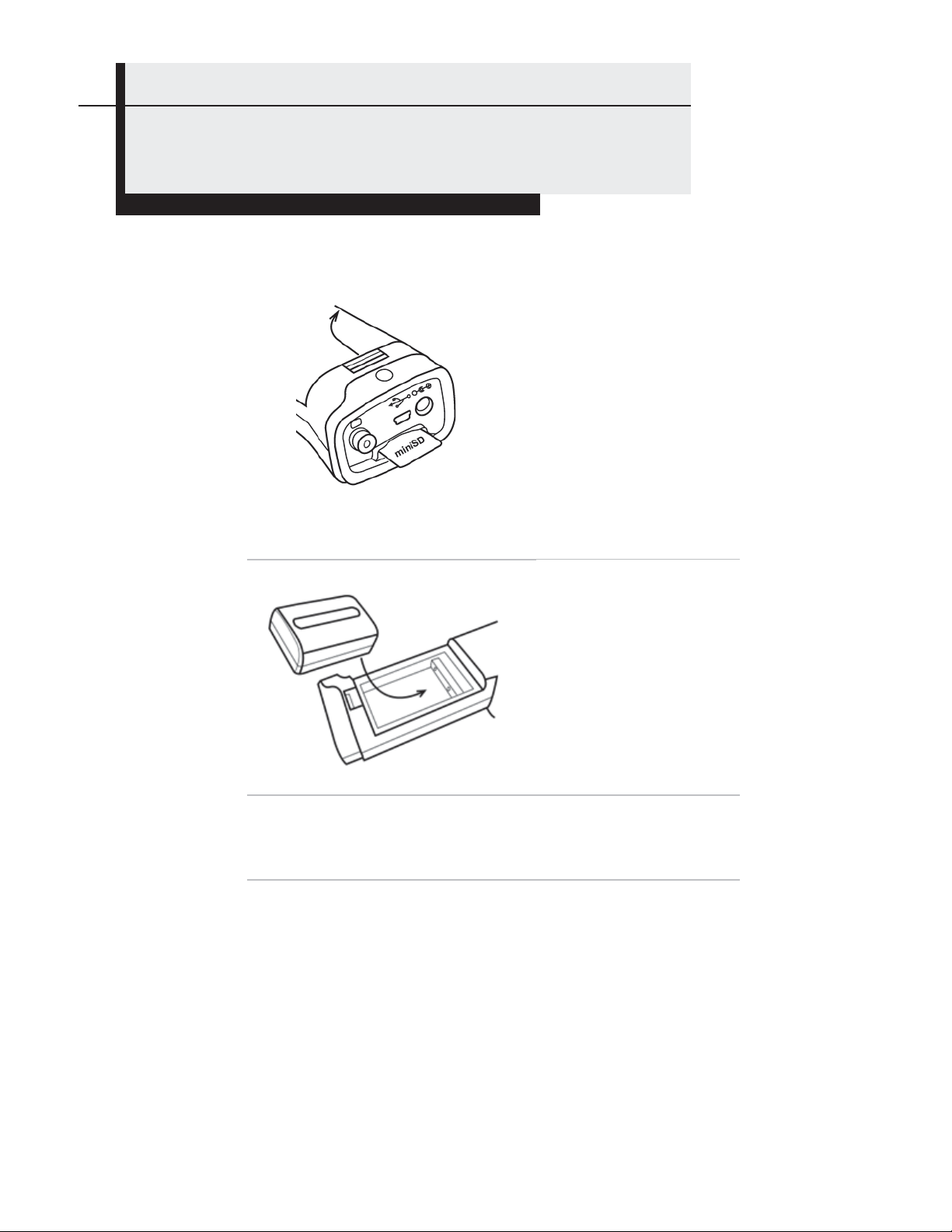
Installing the Battery Pack and Mini SD Card
Install the charged battery into the camera as follows:
1
2
Replace the battery compartment cover.
3
To insert the Mini SD card, position it w ith the p rin ted
4
side up (metal connector side down) in front of the slot
at the bottom of the camera. Push the card in gently
with your fingertip until you feel and hear a click.
Release the battery
compartment latch by
pushing it down and
forward. Lift and
remove the battery
compartment cover.
Align the battery’s edge
with the line inside the
compartment. Push the
battery forward until it
click-locks. Replace the
battery compartment
cover and latch it.
11
Page 12
Setup Instructions
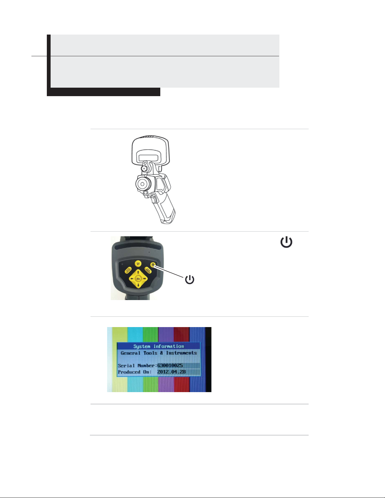
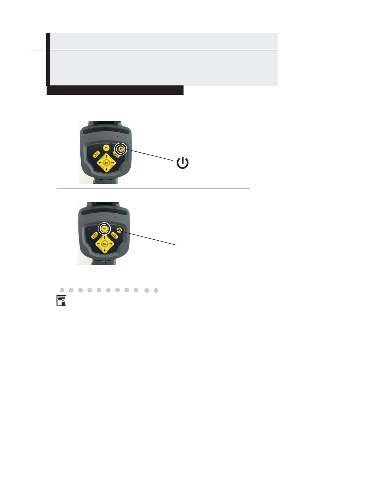
Powering On and Off
The LED at the upper left of the keypad will be lit whenever the camera is powered on.
To power on:
1
2
3
To power off:
Press and hold the power button for three seconds. The LED will
extinguish.
Button
Remove the lens cap and
flip up the LCD to expose
the keypad.
Press and hold the
button for 3 seconds.
On the GTi10 and GTi20, the LED
•
at the upper left of the keypad will
glow green. On the GTi30 and
GTi50, the LED will toggle between
green and blue, indicating that the
camera is ready for a Bluetooth
connection.
After a few seconds, this
System Information startup
screen will appear and take
40 seconds to clear.
12
Page 13
Setup Instructions
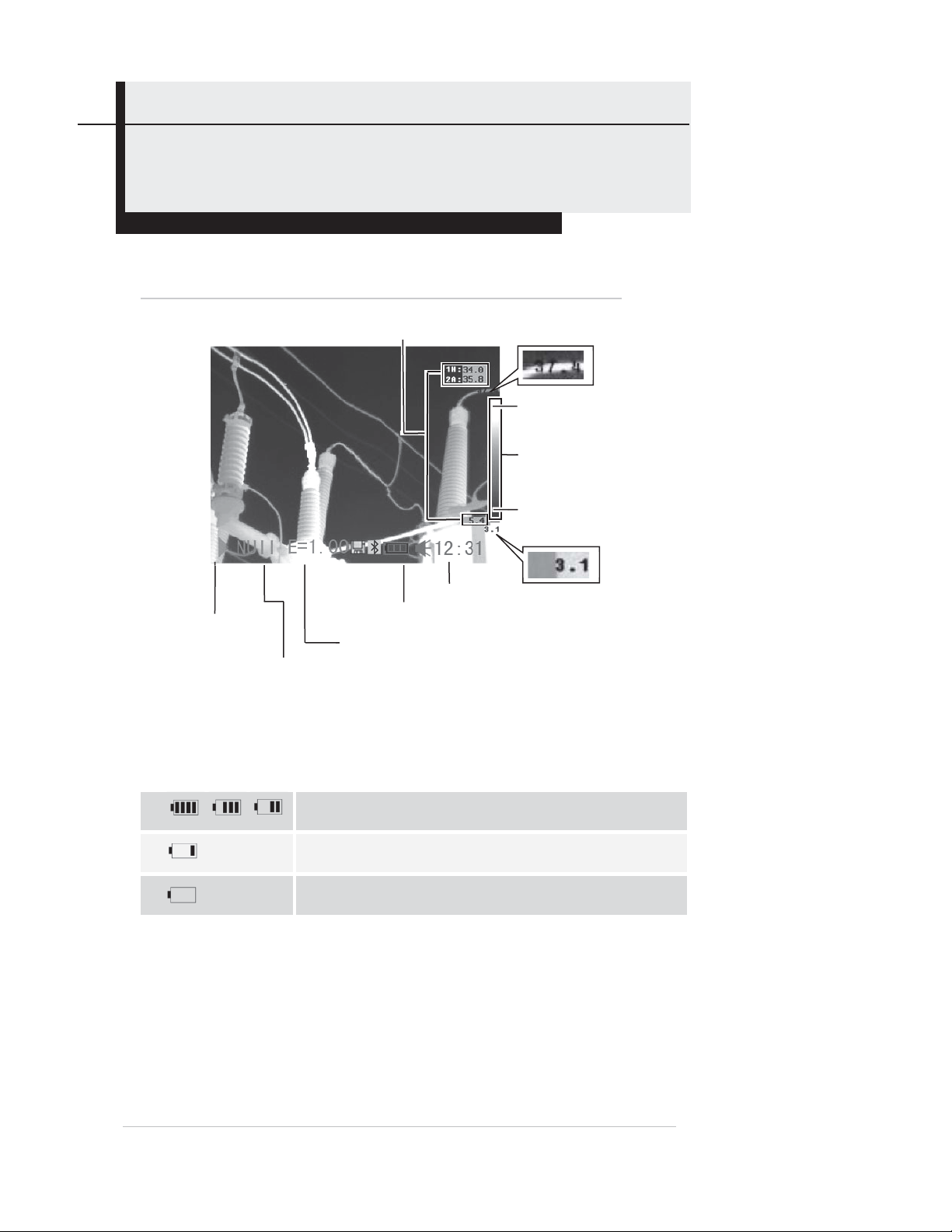
Reading the Display
The LCD’s frame is exactly the same size as the thermal camera’s field of view.
The following information is available on-screen.
Activate
/ Freeze
Operation
indicator
Battery Status Symbols
The following icons indicate battery status on the LCD.
Reading
Battery charge
Current
emissivity
setting
Time
Max. temperature
Upper limit of
color scale
Color
scale
Lower limit of
color scale
Min. temperature
Sufficient battery charge
Low battery
Replace or recharge the battery
13
Page 14
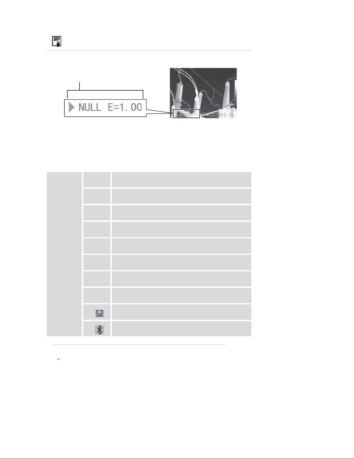
About the operation indicator
The operation indicator at the lower left of the LCD shows the
current operating status of the camera.
Camera status
Menu
Indicates operation in Menu Mode.
Camera
operating
status
Null
SP19
CAP.
AR15
PRO. Indicates that the current analysis tool is profile.
ISO.
E
Represents operation in a non-menu mode, with
no analysis tools selected.
Indicates that the current analysis tool is
spot 1, spot 2 or up to spot 9.
Indicates that the current analysis tool is
auto-tracking spot.
Indicates that the current analysis tool is
area 1, area 2 or up to area5.
Indicates that the current analysis tool is isotherm
nalysis.
urrent emissivity value
Indicates that the SD card is inserted.
Indicates that the Bluetooth headset has been
aired.
To enter NULL mode, press the ESC button
repeatedly until you see NULL at the bottom left of the
14
Page 15
Setup Instructions
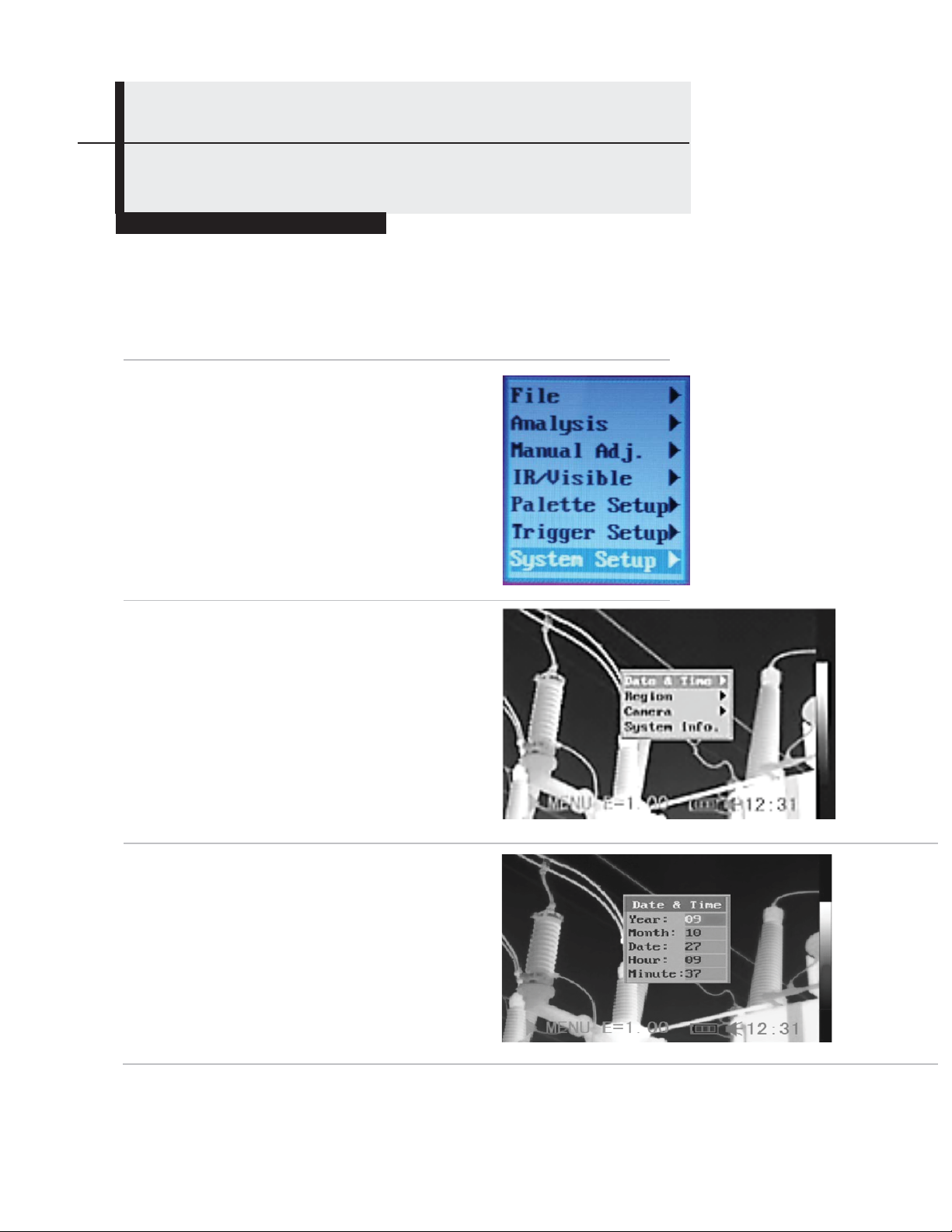
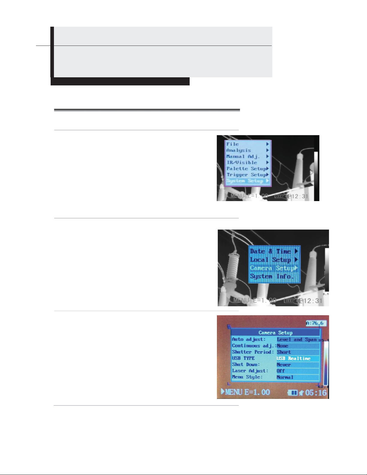
Setting the Date and Time
If you intend to record images, you should set the Date and Time when powering ‘ON’ the thermal
camera for the first time.
Make sure that the thermal camera is in Null mode (see p.14).
1
Press the MENU/ENTER button
2
to call up the Main Menu. Then
press the UP or DOWN key to
navigate to the System Setup
line. Press the MENU/ENTER
button to open the System
Setup menu.
Press the UP or DOWN arrow to select
3
the Date & Time line, then press the
MENU/ENTER button.
a) Use the UP and DOWN arrows to
4
select an item to change, and the LEFT
and RIGHT arrows to set a new value.
b) Repeat for each date and time
parameter.
c) Press the MENU/ENTER button to
save the change(s), or the ESC button
to return to the System Setup menu
without making any changes.
15
Page 16
Setup Instructions
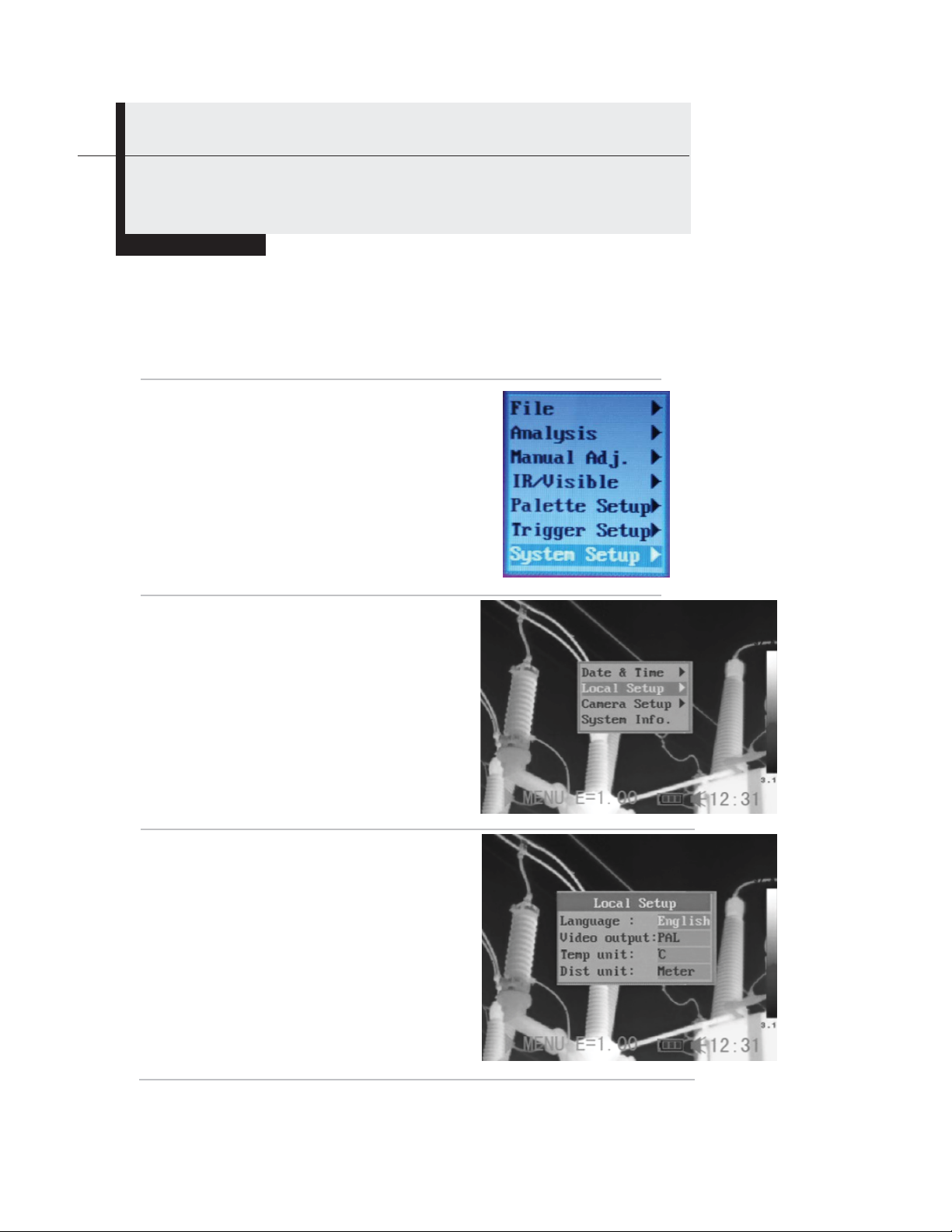
Local Settings
Using this menu item, you can change the language of menus and messages, select either the NTSC or
PAL TV standard, and choose metric or Imperial units for temperature and distance readouts.
Make sure that the thermal camera is in Null mode (see
1
p.14).
Press the MENU/ENTER
2
button to call up the Main
Menu. Then press the UP or
DOWN arrow to navigate to
the System Setup line.
Press the MENU/ENTER
button to open the System
Setup menu.
Press the UP or DOWN arrow
3
to select Local Setup, then
press the MENU/ENTER
button.
a) Use the UP and DOWN arrows to
4
select an item to change, and the
LEFT and RIGHT arrows to set a
new value.
b) Repeat for each parameter you
wish to change.
c) Press the MENU/ENTER button to
save the change(s), or the ESC
button to return to the System Setup
menu without making any changes.
16
Page 17

About Local Settings
Language
Video
output
Temp unit
Distance
unit
Selects the language of the menus and
messages.
Sets the format of the video output of the camera
to PAL or NTSC.
Choose °C or °F as the unit of temperature
measurements.
Chooses meter or foot as the unit of distance
measurements.
17
Page 18
p
Basic Functions
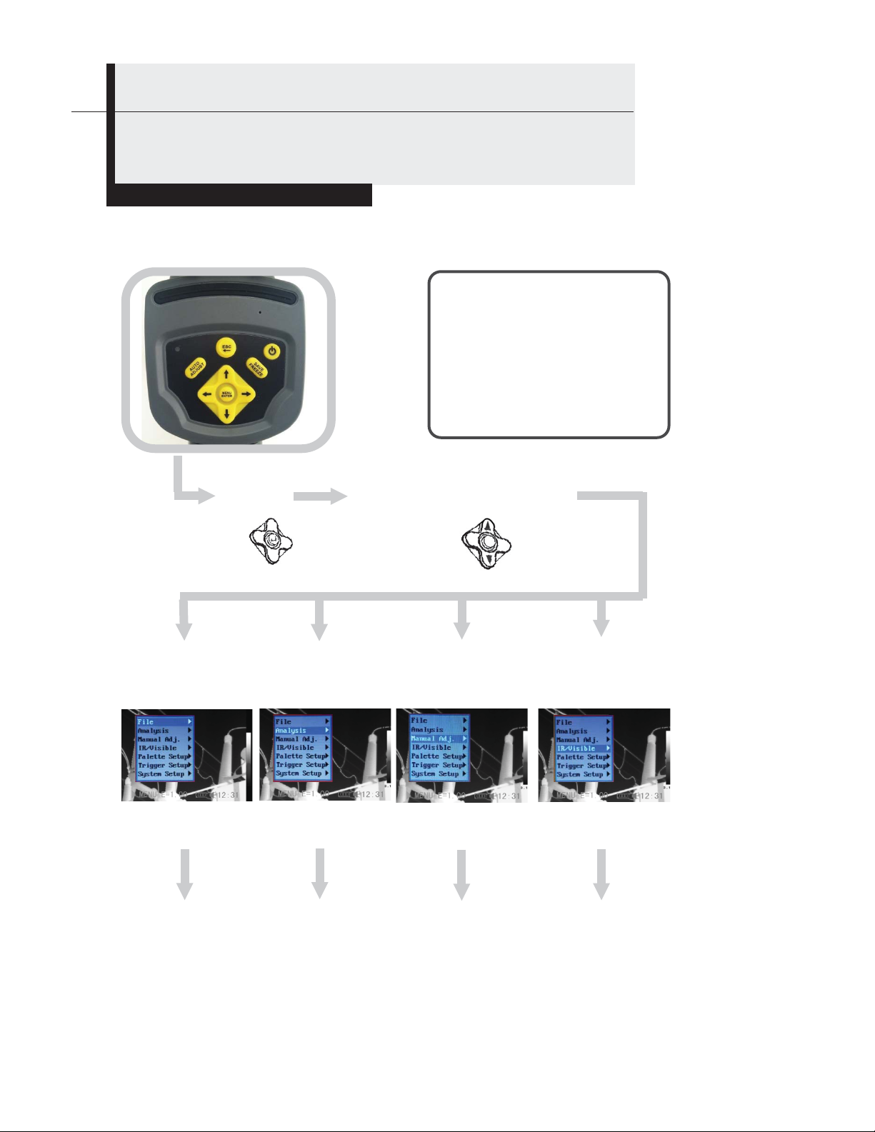
Selecting Menus and Settings
You can select the settings by pressing the MENU/ENTER button.
1 Menu
File
Menu
Analysis
Menu
Press the MENU / ENTER
1
button.
Press the LEFT or RIGHT
2
arrow.
Press the UP or DOWN
3
arrow.
Press the MENU / ENTER
4
button.
2 Select a function item using
Manual Adjust
Menu
System
Setu
Menu
18
Page 19
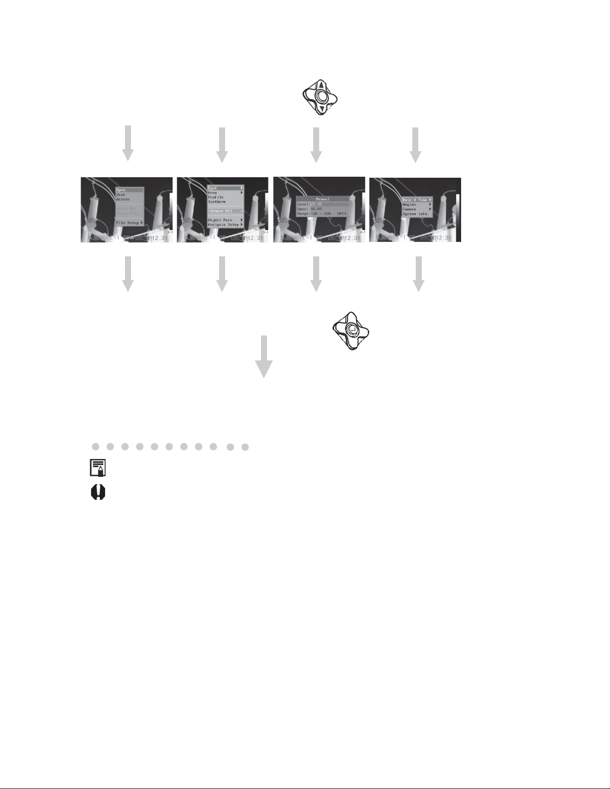
3 Select setting cont ents usi ng
4 Change the settings using
Exit
Displayed menu items will vary according to the operation and setting
contents.
*The menu items may vary among different camera models.
19
Page 20
Basic Functions
Restoring Default Settings
You can reset the menu and button operation settings to default.
1
Turn off the thermal camera.
button
2
The data in storage will not be deleted when you reset the menu and
button operation settings to default.
Press and hold the power
button and the ESC button for
three seconds.
ESC
button
20
Page 21
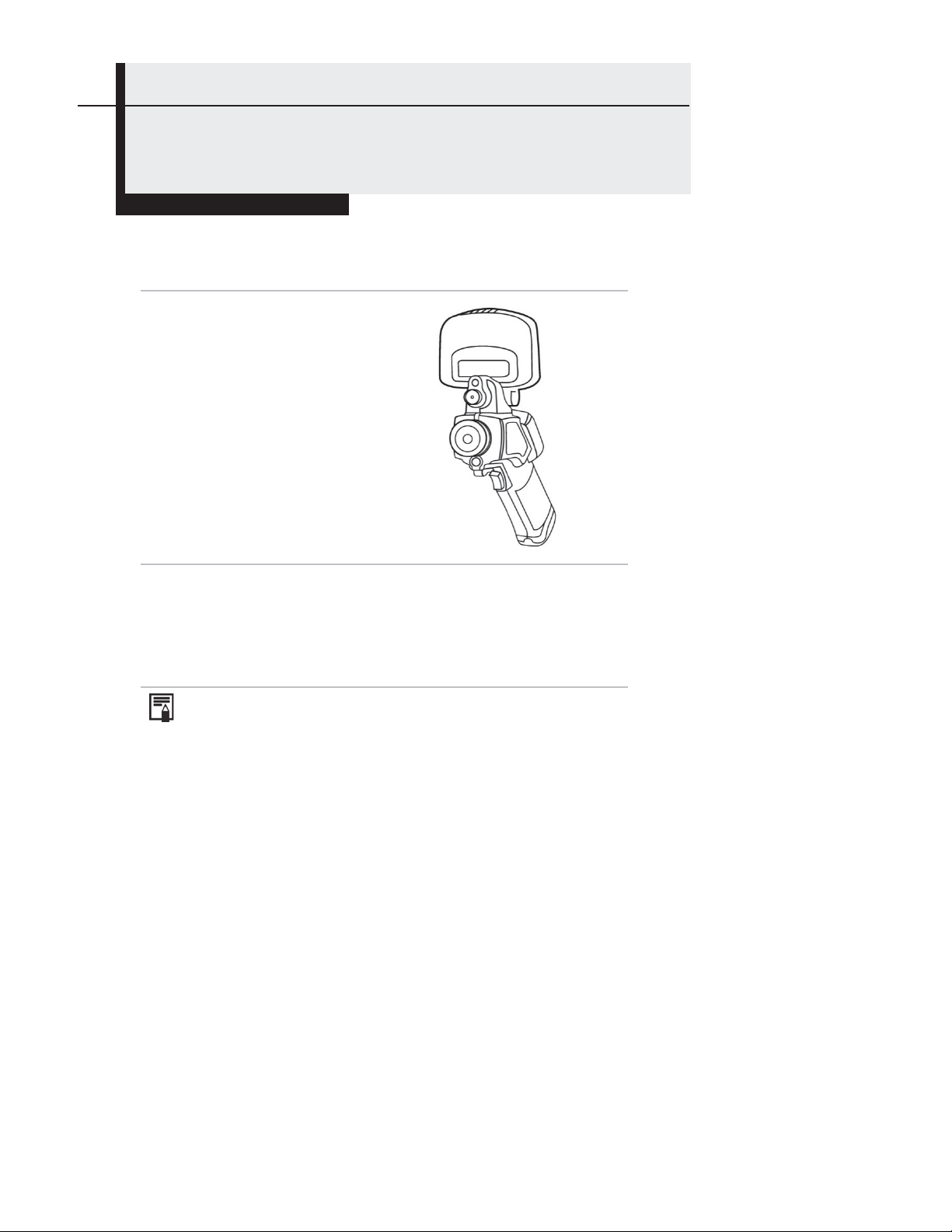
Shooting
Using the LCD
To use the LCD as your monitor for capturing thermal images,
follow the instructions b e lo w.
Open the flip-up LCD screen
1
Using the trigger to turn on the laser pointer (see p. 46),
2
aim the camera at a subject.
1. For the most-accurate temperature measurements, make
sure the target appears in the middle of the LCD.
2. Closing the flip-up screen turns off the LCD and puts the
camera to sleep.
21
Page 22
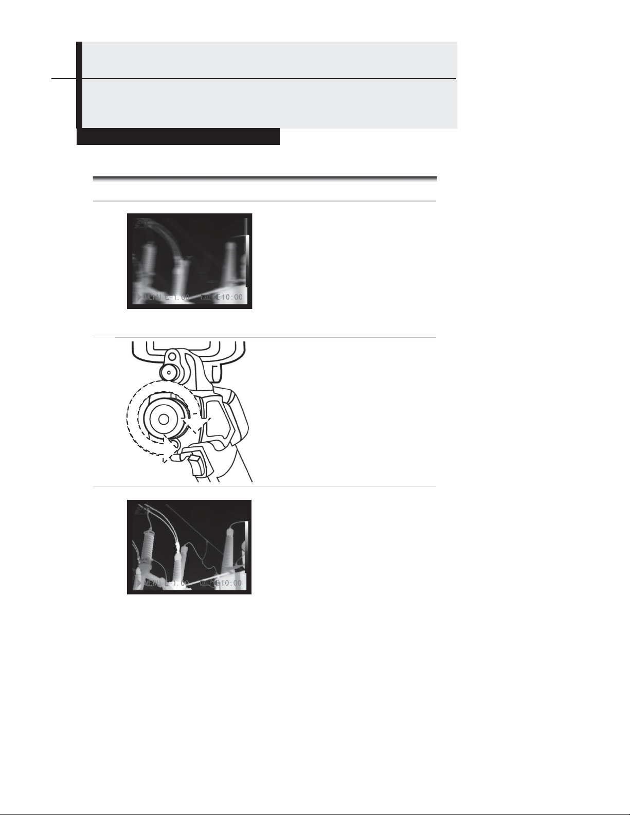
Shooting
Making Camera Adjustments
Manual Focus
1
2
3
Point the thermal camera at
the target.
Turn the focus ring until the
target slips in and out of focus
on the display.
Adjust the focus until the
image is clearest.
22
Page 23
Shooting
Making Camera Adjustments
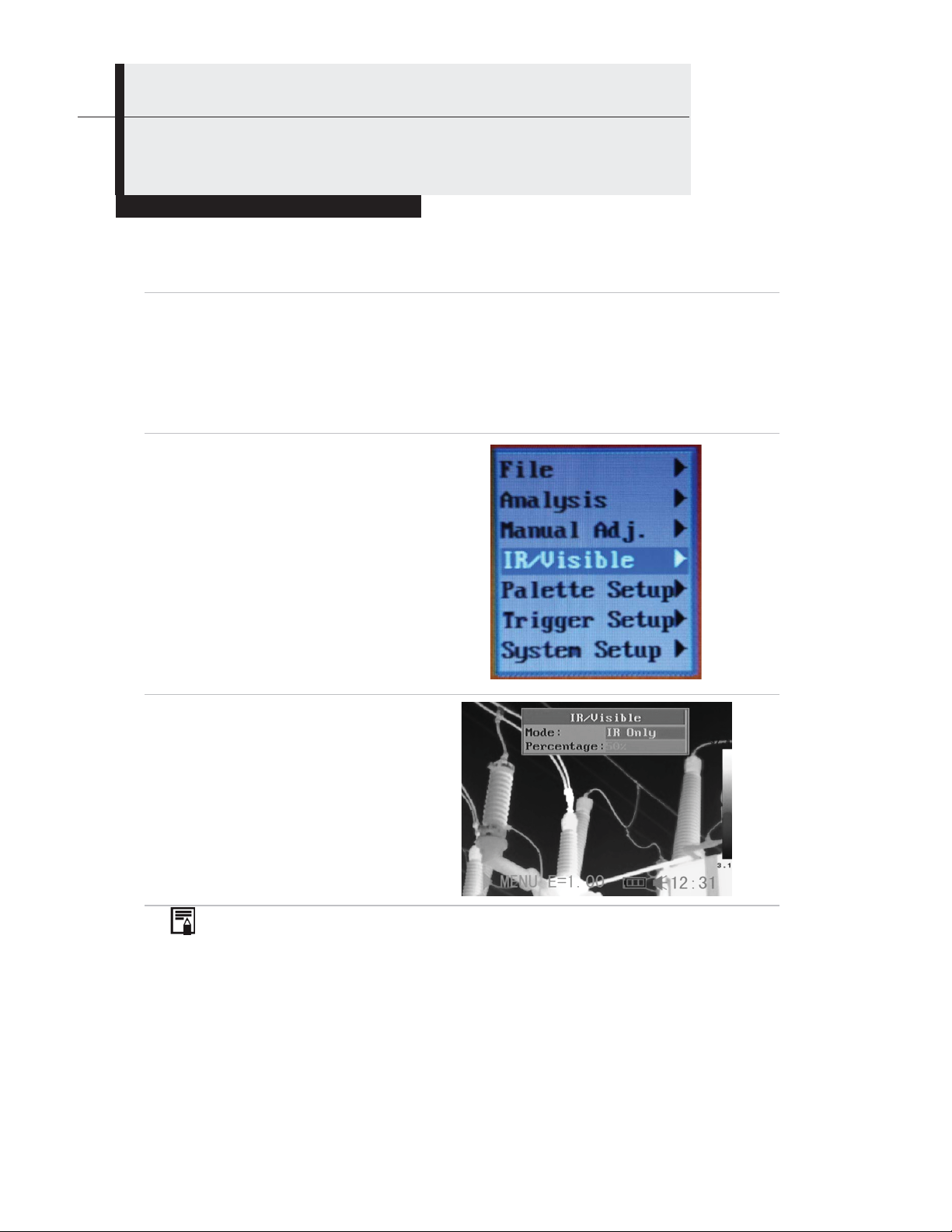
Thermal, Visual and BiVision Image Displays
The GTi20 and GTi30 thermal cameras can also record visual images using a
built-in digital camera. The reason to capture a visual image is to use it as a
reference for a thermal image.
Press the MENU/ENTER button.
1
Press the MENU/ENTER button to
2
call up the Main Menu. Then press
the UP or DOWN arrow to
navigate to the IR/Visible line.
Press the MENU/ENTER button to
display the IR/Visible Setup
menu.
IR/Visible Setup
3
a) Use the LEFT or RIGHT
arrows to select IR Only,
Vision Only, or BiVision.
b) Press the MENU/ENTER
button to save the
selection, or the ESC
button to return to the
System Setup menu
without making a change.
About the Percentage setting: Sets the ratio of IR image to
Visual image to a value between 1% and 100%.
About IR/Visible settings
Sets the ratio of IR image to Visual image to a value between 1% and 100%.
23
Page 24
Shooting
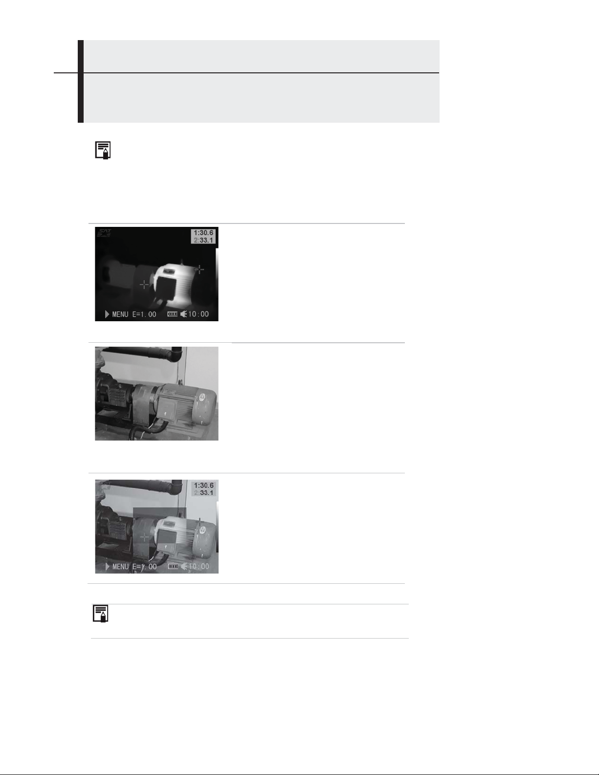
About Fusion Displays
In BiVision display mode, you can see thermal images ‘fuse’ into visible images.
IR Only
In this mode, you can use analysis
tools to analyze the target. But what
you see is the image with pseudo
color.
Vision Only
In this mode, you see the visual
image in full color. But you cannot use
any analysis tools to analyze the
target.
BiVision
In this mode, you see the visual
image in the background with its
thermal image ‘fused’ on it in the
center square. In this mode you can
use any analysis tools to analyze the
target.
In IR Only and BiVision modes, you use the UP and DOWN arrows
to change the span (contrast) of the IR image and the LEFT and
RIGHT arrows to change its level (brightness).
24
Page 25
Shooting
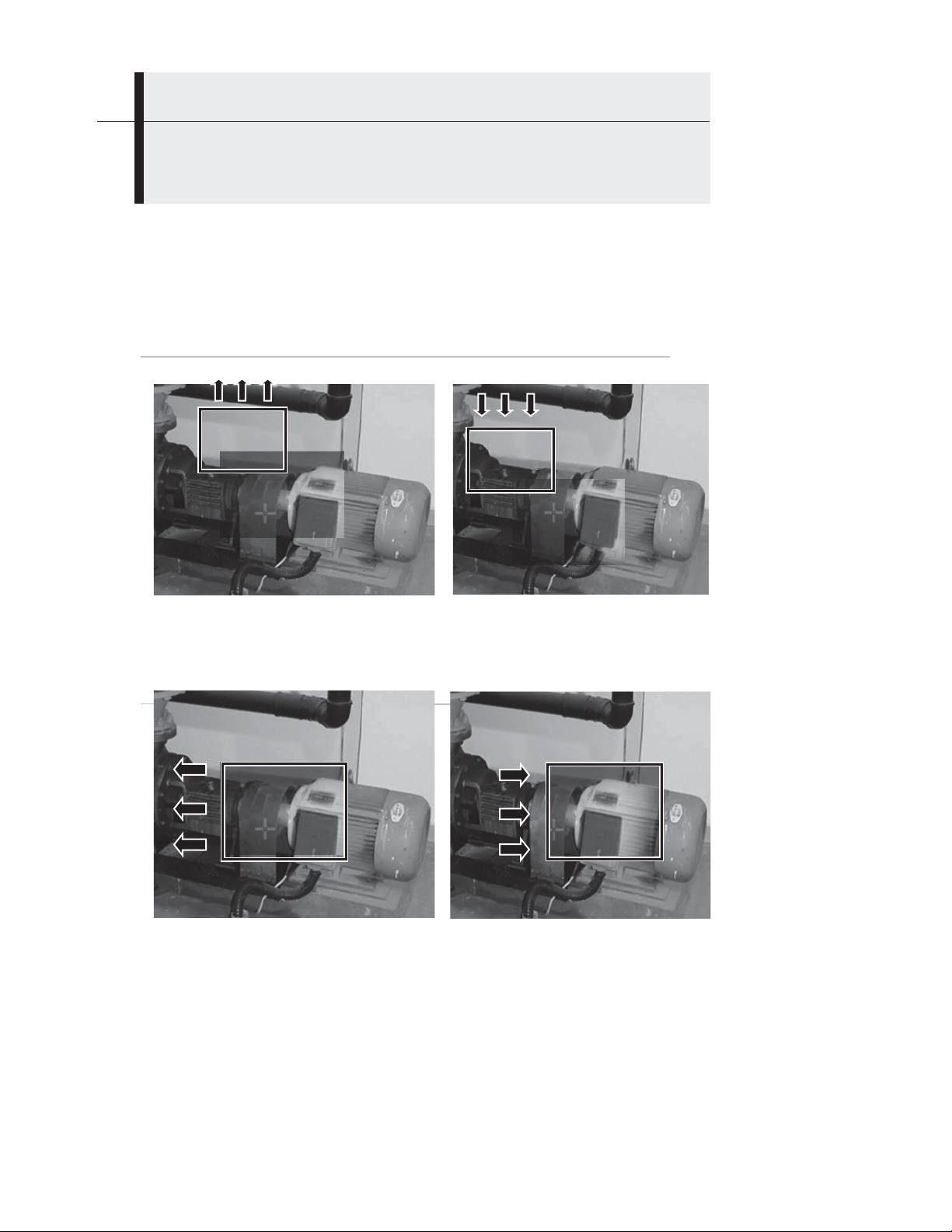
In BiVision display mode, you can move the fusion area using the arrow keys and see thermal
images ‘fuse’ into visible images.
Moving the fusion square
Move the area up
ESC + UP
Move the area left
ESC + LEFT
Move the area down
ESC + DOWN
Move the area right
ESC + RIGHT
25
Page 26

Y
A
Shooting
Making Camera Adjustments
Making Image Adjustments
ou can adjust the level (brightness) and span (contrast) of thermal
images manually or automatically.
uto Adjust
The camera will aut o matically adjust the brightness, sp a n o r b o th
parameters when you press the Auto Adjust button. How you set
the Auto Adjust line of the Camera Setup menu (see p. 30)
determines which of the three possible adjustments is made.
26
Page 27
Shooting
Making Camera Adjustments
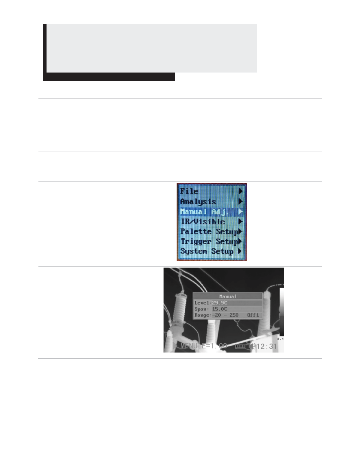
Making Manual Adjustments
You can manually adjust the level and span of thermal images by using a menu or
the arrow buttons. Use
an image and the LEFT and RIGHT arrows to change its level (brightness).
Using the Manual adjust menu
Press the MENU/ENTER button to call up the Main Menu.
1
Press the UP or DOWN arrow to
2
navigate to the Manual Adj. line. Then
press the MENU/ENTER button to
open the Manual Adjust menu.
Setting Level and/or Span
3
a) Use the UP and DOWN arrows to
select Level or Span. (Range refers to
the Temperature Measurement Range
of the camera’s lens, which is not
adjustable. Appendix I correlates this
line to the kind of lens installed)
b) Use the LEFT and RIGHT arrows to
adjust the level or span. Then press
the MENU/ENTER button to save the
change, or the ESC button to return
to the System Setup menu without
making a change.
the UP and DOWN arrows to change the span (contrast) of
27
Page 28
Shooting
Making Camera Adjustments
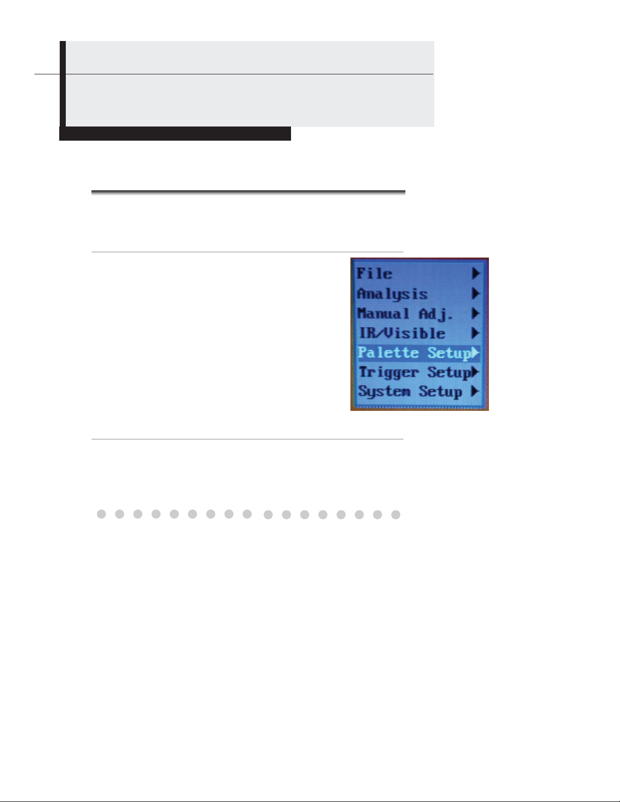
Palette Settings
Press the MENU/ENTER button to open the Main Menu.
1
a) Press the UP or DOWN arrow to
2
navigate to the Palette Setup line.
Then press the MENU/ENTER button
to open the Palette Setup menu.
b) The default palette is Iron. Use
the LEFT and RIGHT arrows to
change the palette. The other
options are Iron Inverted, Rainbow,
Feather, Grey and Grey Inverted.
After you make your choice, press the MENU/ENTER
3
button to save the selection, or press the ESC button to
return to the Main Menu without saving.
28
Page 29
Shooting
Making Camera Adjustments
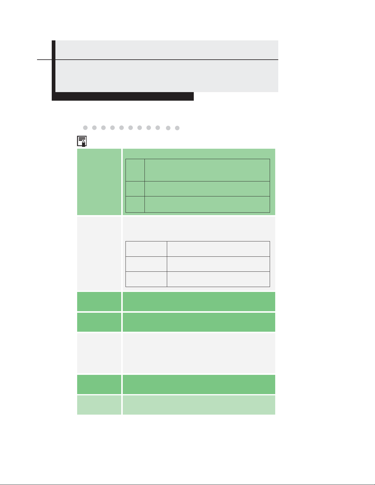
Image/camera Settings
Press the MENU/ENTER button to open the Main Menu.
1
Press the UP or DOWN arrow to navigate to
2
the System Setup line. Then press the
MENU/ENTER button to open the System
Setup menu.
Press the UP or DOWN arrow to navigate to
3
the Camera Setup line. Then press the
MENU/ENTER button to open the Camera
Setup menu.
Use the UP and DOWN arrows to select a
4
parameter.
a) Use the LEFT or RIGHT arrows to
select IR Only, Vision Only, or BiV isio n .
b) Press the MENU/ENTER button to
save the selection, or the ESC button to
return to the System Setup menu
without making a change.
29
Page 30
Shooting
Making Camera Adjustments
About Image Settings
Sets the function of the AUTO ADJUST button
The camera will au tomatically adjust the
and
level (brightness) and span (contrast) of
the image to the optimum setting.
The camera will automatically adjust the
level (brightness) of the image.
The camera will automatically adjust the
span (contrast) of the image.
Level
None
Auto adjust
Continuous
adj
Level
Span
Level
Span
Determines whether or not the brightness and
contrast of images shown on-screen are adjusted
automatically
Level and span
Brightness and contrast are
adjusted automatically.
Only brightness is adjusted
automatically.
Brightness and contrast are NOT
adjusted automatically.
Shutter
period
USB TYPE
Sets the period of auto-adjusting.
The options are USB Realtime and USB Remove
Disk
Sets the Auto Power Off interval—the time at wh ich
Shut Down
the camera will automatically power off if no keypad
entries are made. The options are 2 minutes, 5
minutes, 10 minutes and never.
Laser Adjust Turns the laser pointer on or off.
Menu Style
Sets the menu style. The options are Normal,
Translucence and Lucency.
30
Page 31

Y
Shooting
Making Camera Adjustments
Freezing / Activating an Image
ou can activate/freeze a thermal image by configuring the trigger
to do so.
Make sure that the thermal camera is in null mode (see
1
p. 14).
Menu.
Press the UP or DOWN arrow to
2
navigate to the Trigger Setup line.
Then press the MENU/ENTER button
to open the Trigger Setup menu.
After this operation, press the MENU/ENTER button to
3
save the selection, or press the ESC button to return to
the System Setup menu without saving.
Press the MENU/ENTER button to open the Main
Use the LEFT and RIGHT arrows
•
to select Freeze/Live among the
three options for the trigger. (The
other two options are Torch On
and Save File.) To set up the
trigger for Torch Off, press the
MENU/ENTER button while the
display shows Torch On.
31
Page 32

Shooting
Using Analysis Tools
Changing Object/global Settings
Make sure that the thermal camera is in null mode (see p.
1
14).
Press the MENU/ENTER button to open the Main Menu.
Press the UP or DOWN arrow to
2
navigate to the Analysis line. Then
press the MENU/ENTER button to
open the Analysis menu.
Use the DOWN arrow to navigate
3
down to the Object Para. line.
Then press the MENU/ENTER
button.
Set the analysis parameter.
4
a) Use the UP and DOWN arrows to
select an item to change, and the
LEFT and RIGHT arrows to set a
new value.
b) Repeat for each item you wish to
change.
c) Press the MENU/ENTER button
to save the setting(s), or the ESC
button to return to the Analysis
menu without saving.
32
Page 33

g
About analysis parameters
Object
Emiss
Distance
Amb Temp
Humidity
Comp. Obj.
Ref Temp
Selects the object (a spot or area) whose
parameters you wish to measure.
Emissivity is a measure of an object’s reflectivity
in the infrared spectrum. You can optimize the
camera’s measurement accuracy for a specific
object by entering its emissivity within the
Analysis menu. Emissivity is a number with no
units between 0 and 1. A table in the Appendix
lists the emissivities of dozens of common
materials.
Use this field to enter the actual distance of the
object from the camera. Doing so improves
measurement accuracy.
Enter the ambient temperature in this field.
Doing so improves measurement accuracy.
Enter the ambient humidity in this field. Doing
so improves measurement accuracy.
Comp Obj1 can be set as any spot or area;
Comp Obj2 can be set as a reference
temperature (Ref Temp) or as any spot or area.
The difference between the temperatures of the
two objects will appear at the right bottom
corner of the screen.
Sets a reference temperature to compare with
the spot/area/profile tool.
The readin
of Comp. Obj.
33
Reading
Page 34

Shooting
Using Analysis Tools
Setting Analysis Parameters
Make sure that the thermal camera is in null mode (see p.
1
2
3
4
Press the MENU/ENTER button to open the Main Menu.
14).
Use the UP or DOWN arrow to
navigate to the Analysis line. Then
press the MENU/ENTER button to
open the Analysis menu.
Use the UP or DOWN arrow to
navigate to the Analysis Setup line.
Then press the MENU/ENTER
button.
Setting analysis parameters.
a) Use the UP and DOWN arrows to
select an item to change, and the
LEFT and RIGHT arrows to set a
new value.
b) Repeat for each parameter you
wish to change.
c) Press the MENU/ENTER button to
save the setting(s), or the ESC
button to return to the Analysis
Setup menu without saving.
34
Page 35

Alerts
About analysis settings
There are two kinds of temp-alert: Upper-limit alert and Lower-limit alert.
1.Upper-limit alert
If you set the Alert line of the Analysis Setup menu to “on” and the Spot line of the
Analysis menu to “Maximum”, the spot analysis tool "max sp10" will automatically
capture the hottest spot within the screen. If this temperature is higher than the value
you set for the Alert Temp line of the Analysis Setup menu, the value at the top right of
the screen will turn red and the beeper will sound.
2.Lower-limit alert
If you set the Alert line of the Analysis Setup menu to “on” and the Spot line of the
Analysis menu to “Minimum”, the spot analysis tool "max sp10" will automatically
capture the coldest spot within the screen. If this temperature is lower than the value
you set for the Alert Temp line of the Analysis Setup menu, the value at the top right of
the screen will turn red and the beeper will sound.
Alert
Temp
Correct
Temp
Saturation
Color
Isotherm
Width
Isotherm
Color
Sets the temperature of “Alert”.
Corrects the measured temperature value of the camera to improve measurement
accuracy under special circumstances.
When set to “On”, green takes the place of the color that stands for the highest
temperature.
Sets the width of the isotherm interval. The width can be adjusted from 0.1oF to the
upper limit of the maximum temperature measurement range under this condition.
Sets the color of the isotherm interval. The options are Transparent, Green, Black and
White.
Determines the isothermal analysis mode. Five modes are available: Dual Above, Dual
Below, Above, Below and Interval.
Displays the isothermal interval in one color and parts whose temperature
is above the upper limit of the isothermal interval in a different color
Displays the isothermal interval in one color and the parts whose
temperature is below the lower limit of the isothermal interval in a different
color
Displays the isothermal interval and parts whose temperature is above
the upper limit of the isothermal interval in the same color
Displays the isothermal interval and areas whose temperature is below
the lower limit of the isoth e rmal interval of the same color
Displays the isothermal interval in one color and all other areas in normal
pseudocolor mode
Isotherm
Type
Dual
Above
Dual
Below
Above
Below
Interval
A value from 1 to 100 corresponding to the isotherm interval’s percentage area,
Isotherm
Alert
relative to the overall screen area screen. For example, for a isotherm span of 35 to
40oF and an isotherm alert of 50, if more than 50% of the isotherm area is between 35
and 40oF, the alarm will sound.
SpotTemp
Color
Use the LEFT and RIGHT arrows to choose the color of the spot temperature box. The
options are White, Black, Blue, Red, Purple, Green, Aqua and Yellow
35
Page 36

Shooting
Using Analysis Tools
Setting Spot Analysis Parameters
This section explains how to apply spot analysis tools to the thermal
image.
1
2
3
Make sure that the thermal camera is in null mode (see p.
14).
Press the MENU/ENTER button to open the Main Menu.
Press the UP or DOWN
arrow to navigate to the
Analysis line. Then press
the MENU/ENTER button to
open the Analysis menu.
Use the UP or DOWN arrow to
navigate to the Spot line.
press the MENU/ENTER button to
open the Spot submenu.
Then
36
Page 37

Selecting a spot
4
Use the UP or DOWN arrow to select a
•
spot, and then press the MENU/ ENTER
button.
Spot 10 will automatically track the
•
hottest and coldest temperature spot
within an area whose shape and size
can be set by the user (see p. 45). Use
the LEFT or RIGHT arrow to select the
Maximum spot or Minimum spot.
Moving the spot
5
Start from Step 1 to select a spot to
•
analyze.
Use the UP, DOWN, LEFT and RIGHT
•
arrows to move the spot.
Press the MENU/ENTER button to fix the
•
position of the spot.
The temperature readout of the spot
changes in real time.
Removing a spot
6
Use Steps 1 through 4 to select a spot.
•
Press and hold the ESC button to remove the spot.
•
Spot No.
Temperature
reading
37
Page 38

Shooting
Using Analysis Tools
Setting Area Analysis Parameters
This section explains how to apply area analysis tools to the
thermal image.
1
2
3
4
Make sure that the thermal camera is in
null mode (see p. 14).
MENU/ENTER button to open the Main
Menu.
Use the UP or DOWN arrow to navigate to
the Analysis line. Then press the
MENU/ENTER button to open the Analysis
menu.
Use the UP or DOWN arrow
to navigate to the Area line.
Then press the
MENU/ENTER button to open
the Area submenu.
Setting the analysis area.
Press the UP or DOWN arrow to select one
•
or more areas, then press the MENU/
ENTER button. A check mark will appear to
the left of the selected area(s) and one or
more boxes will appear on the screen.
A reading in a box with a label at its left will
•
appear at the top right corner. The reading
represents the highest/lowest/average
temperature of the current area.
Press the LEFT or RIGHT arrow to select
•
the maximum, minimum or average
temperature for display. The letter in the
label to the left of the box indicates which
temperature is displayed: H for the highest
temperature, L for the lowest, and A for the
average.
Press the
38
Page 39

If Area 5 is selected, its maximum,
A
•
minimum and average temperatures will
appear in separate boxes at the same time.
5
Moving the area.
Use Steps 1 through 4 to
•
select an area.
Use the UP, DOWN,
•
LEFT and RIGHT arrows
to move the area.
The temperature
Area
No.
readout of the area
changes in real time.
6
Removing an area
Use Steps 1 through 4 to select
•
an area.
Press and hold the ESC button
•
to remove the area.
bout changing the shape of the analysis area
Readings
UP and LEFT arrows
DOWN and LEFT arrows
UP and RIGHT arrows
DOWN and RIGHT arrows
39
Page 40

Shooting
Using Analysis Tools
Profile Analysis
Make sure that the camera is in
1
null mode (see p. 14).
MENU/ENTER button to open the
Main Menu.
Press the UP or DOWN arrow to
2
navigate to the Analysis line. Then
press the MENU/ENTER button to
open the Analysis menu.
Use the UP or DOWN arrow to
3
navigate to the Profile line.
press the MENU/ENTER button to
open a profile.
Moving a profile.
4
5
Start from Step 1 to select profile
•
analysis.
Press the UP or DOWN arrow to
•
move the profile.
Removing a profile.
Use Steps 1 through 3 to select a profile.
•
Press and hold the ESC button to remove it.
•
Press the
Then
Temperature
distribution
40
Page 41

Shooting
Using Analysis Tools
Isotherm Analysis
1
2
Make sure that the camera is in null
mode (see p. 14).
MENU/ENTER button to open the Main
Menu.
Press the UP or DOWN arrow to navigate
to the Analysis line. Then press the
MENU/ENTER button to open the Analysis
menu.
Use the UP or DOWN arrow to
3
navigate to the Isotherm line, then
press the MENU/ENTER key. Areas
of concern will be highlighted in
color.
Setting the isotherm range.
4
Start from Step 1 to set or select
•
isotherm analysis.
Press the UP or DOWN arrow to
•
select isotherm range. IL and IH
will appear at the bottom right
corner of the screen. IH is the high
limit and IL is the low limit of the
isotherm range.
(To change the isotherm type,
width, alert and color, see p. 35)
Press the
41
Page 42

this
Shooting
Using Analysis Tools
Removing Analysis Tools
This section explains how to remove analysis tools that you have
activated.
Make sure that the camera is in null mode (see p. 14). Press
1
the MENU/ENTER button to open the Main Menu.
Press the UP or DOWN arrow to navigate to
2
the Analysis line. Then press the
MENU/ENTER button to open the Analysis
menu.
Use the UP and DOWN arrows to
3
navigate to the Remove All line.
Press the LEFT or RIGHT arrow
•
to cycle through Remove All,
Remove Spot, Remove Area,
Remove Profile and Remove Iso
.
Press the MENU/ENTER button to save the selection, or
4
the ESC button to return to the Analysis menu without
saving.
42
Page 43

Shooting
Saving Images
You can save images in either of two ways: 1) by using a pulldown in the File menu or 2) by
configuring the trigger to save files.
Using the File menu to save files
Make sure that the camera is in null mode (see p. 14). Press the
1
MENU/ENTER button to open the Main Menu.
The Main Menu will open with the File
2
line highlighted. Press the
MENU/ENTER button to open the File
menu.
Use the UP or DOWN arrow to navigate
3
to the Save line. Then press the
MENU/ENTER button to save the
image.
The display mode determines the file
type of the saved image (see p. 23).
The file name of the saved image will
4
be displayed on-screen.
43
Page 44

Shooting
Using the trigger to save files
1
2
3
Make sure that the camera is in null mode (see p. 14) Press the
MENU/ENTER button to open the Main Menu.
Press the UP or DOWN arrow to navigate to the
Trigger Setup line. Then press the MENU/ENTER
button to open the Trigger Setup menu.
Use the LEFT or RIGHT arrow to select Save File.
To use the trigger to save a file, squeeze the trigger and hold it for
at least three seconds. The image will be saved in the current folder
(see p. 49) and the operation will be confirmed on-screen.
After this operation, press the MENU/ENTER button to save the
4
selection, or the ESC button to return to the Main menu without saving.
44
Page 45

V
Shooting
Attaching Voice Memos to Images
oice recording
ou can attach a voice message of up to 30 seconds to any image (GTi30 only)
Install the Bluetooth headset (included with GTi30, optional for
1
GTi10 and GTi20) using the instructions on p. 56
Freeze an image (p. 31), then press the MENU/ENTER button to open
2
the Main Menu.
The Main Menu will open with the
3
File line highlighted. Press the
MENU/ENTER button to open the
File menu.
Use the UP or DOWN arrow
4
to navigate to the Voice Rec.
line. Then press the
MENU/ENTER button
The message Voice Recording will
•
appear on the LCD.
Speak into the microphone of the headset. To stop recording, press the
5
ESC button.
Save the image (see p. 44). (Note: Adding a voice message does not
6
increase the size of an image file.)
45
Page 46

Shooting
Configuring the Trigger
By default,
trigger to:
squeezing the trigger saves the current display as an image file. You can also configure the
Freeze/Activate an image
1. Press the MENU/ENTER button to open the Main Menu.
2. Press the or button to navigate to the Trigger Setup line. Then press the MENU/ENTER
button to open the Trigger Setup Menu.
3. Use the or button to highlight Freeze/Live. Then press the MENU/ENTER button to save
the selection.
4. In this configuration, squeezing the trigger freezes the current image.
Turn the torch on and off
1. Press the MENU/ENTER button to open the Main Menu.
2. Press the or button to navigate to the Trigger Setup line. Then press the MENU/ENTER
button to open the Trigger Setup Menu.
3. Use the or button to highlight Torch On.
4. Note: Pressing the MENU/ENTER button changes the selection from Torch On to Torch off
(disabling the torch).
5. In this configuration, squeezing and holding the trigger and then pressing the Auto Adjust button
turns on the torch. Performing the same actions the next time turns off the torch.
Turn the laser pointer on and off
1. Squeezing and holding the trigger for 3 seconds turns the laser pointer on and off.
2. You can configure the trigger to turn the flashlight (torch) and laser pointer on and off. You can
also use the SAVE/FREEZE button to change the trigger setting.
Toggle between Save File and Freeze/Live
Pressing the SAVE/FREEZE button toggles the trigger’s action between Save File and
Freeze/Live.
1. C
2.
46
Page 47

Playback and Erase
Opening Images
You can view and analyze saved images on the LCD monitor.
Make sure that the camera is in null mode (see p. 14).
1
Press the MENU/ENTER button to open the Main Menu.
The Main Menu will open with the
2
File line highlighted. Press the
MENU/ENTER button to open the
File menu.
The File menu will open with the
3
Open line highlighted. Press the
MENU/ENTER button.
Use the LEFT and RIGHT arrows to
4
select an image. Then press the
MENU/ENTER button to open it.
47
Page 48

How to select an image
If you select Open or Delete in the File menu, a box like the
1
one shown below will appear at the bottom left of the screen.
File amount
of current folder
Serial number
of current file
Seri al number of
current folder
00001/00 003/002/003
File count
<DIR>GZSA T001
Open SAT00001.SAT
File Name
If the image you wish to open or delete is not in the current
2
folder, use the LEFT and RIGHT arrows to browse for it.
To activate the image, press the SAVE/FREEZE button.
3
48
Page 49

Selecting a folder and filename
Make sure that the camera is in null mode (see p. 14).
1
Press the MENU/ENTER button to open the Main Menu.
The Main Menu will open with the File
2
line highlighted. Press the MENU/ENTER
button to open the File menu.
Use the UP or DOWN arrow to navigate
3
to the File Setup line. Then press the
MENU/ENTER button to open the File
Setup submenu.
The File Setup submenu will open with
4
the Directory Name line highlighted.
Use the LEFT and RIGHT arrows to
navigate to the desired folder. On this
screen, “File number” represents the
number of files in the current folder.
Use the DOWN arrow to navigate d o w n to th e F ile
5
Name line. Then press the LEFT or RIGHT arrow to
select the filename.
49
Page 50

Playback and Erase
Playing Back Voice Memos
To play back the voice messages you attach to images:
Install the Bluetooth headset (included with GTi30, optional for GTi10 and
1
GTi20) using the instructions on p. 56.
Freeze an image (see p. 31), then press the MENU/ENTER button to open the
2
Main Menu.
The Main Menu will open with the
3
File line highlighted. Press the
MENU/ENTER button to open the
File submenu.
Use the DOWN arrow to navigate
4
to the Voice Play line. Then press
the MENU/ENTER button.
• If a voice message is attached to
the frozen image, it will play and
the message, “Playing Record”
will appear on the LCD.
To end the playback of a voice message, press the ESC button.
5
50
Page 51

Playback and Erase
Erasing Images
Erased images cannot be recovered. Exercise caution before
erasing an image.
Make sure that the camera is in null mode (see p. 14). Press the
1
MENU/ENTER button to open the Main Menu.
The Main Menu will open with the
2
File line highlighted. Press the
MENU/ENTER button to open the
File submenu.
Use the DOWN arrow to select the
3
Delete line. Then press the
MENU/ENTER b u tto n .
Select an image (see p. 48), and
3
then press the MENU/ENTER
button to delete it.
51
Page 52

Uploading Images
Images stored on the camera’s Mini SD memory card can be transferred via the
included SD card reader to any computer with a USB port.
Swing the rubber cover on the bottom of the camera
1
down to expose jacks and the mini SD card in its socket.
Lightly press on the Mini SD card
2
with the tip of your finger and it
will pop out.
Insert the card into the supplied SD card reader and
3
plug the card reader into a USB port of your computer.
MiniSD card
52
Page 53

w
Camera Connections
Charging the Battery Directly
You can charge the battery directly using the optional power adaptor.
Swing the rubber cover on the bottom of the camera
1
down to expose the power terminal on the right side.
Insert the single-plug end of the power adaptor into the
2
3
4
terminal.
Plug the other end of the adaptor into a 110VAC outlet.
The LED on the camera’s keypad will flicker
hile the battery is charging. When charging is
complete, the LED will stop flickering and steadily
glow green.
Unplug the power adaptor from the power outlet
after charging.
53
Page 54

Camera Connections
Connecting to a TV Monitor
You can increase the size of camera images that you view and analyze by using
the supplied video cable to connect the camera to a TV or TV monitor.
1
2
Shown: RCA to BNC connector
Choose appropriate connector
for your Video-In jack
Swing the rubber cover on the
bottom of the camera down to
expose the yellow Video Out jack.
Insert the RCA mini-plug end of the
supplied video cable into the jack.
The other end of the cable is also an
RCA plug which will mate to th e
supplied BNC connector if needed.
Use the appropriate connector with
the Video In jack on your TV or TV
monitor.
Be sure to set the TV’s controls to
External Video In.
54
Page 55

Camera Connections
Connecting to a Computer
The camera's USB jack and included USB cable cannot be used to transfer
stored images to a PC. To transfer images stored on the mini SD card: 1)
eject the card, 2) plug it into the supplied SD card reader, and 3) insert the
card reader into the USB port of a PC. This procedure is also described on p.
52.
The camera's USB jack and cable can be used to stream live video to a PC.
but only from a GTi30 or GTi50. The driver that enables a PC to recognize the
GTi30 or GTi50 as an external storage device is on the disc containing
General's Professional Analysis & Reporting Software package. This
package is available for purchase as an optional accessory.
If you use the USB cable to connect the camera directly to a PC via a USB
port, the PC will respond by displaying the notification box shown below.
55
Page 56

t
Camera Connections
Using the Bluetooth Headset
You can use the camera to capture, analyze and save thermal videos as well as
thermal images. Doing so requires purchase of optional real-time software and use
of the supplied USB cable. The controls for starting and stopping the recording of
thermal video clips are on the software, rather than on the camera. A separate
user’s manual for the software explains how to capture, save, and analyze thermal
video clips.
Follow the steps below to install the Bluetooth headset (included with t he GTi30 and GTi50; optional
for the GTi10 and GTi20) for the first time.
Before beginning, fully charge the Bluetooth headset. If the power indicator i s red, the Bluetooth
headset needs additional charging. When the Bluetooth piece is fully charged, i ts power indicator will
turn blue.
Turn off the camera and Bluetooth headset.
1
Turn on the Bluetooth headset
2
first.
Press and hold the power button
for about 4 seconds. You will see
the power indicator begin to
blink red and blue. The headset
will remain in this “pairing”
mode for about 90 seconds.
Turn on the camera.
3
When you do, the green LED on
the camera keypad and the blue
indicator on the Bluetooth
headset will begin flashing
together. At this point, the
camera is preparing to pair up
with the Bluetooth headset.
Press the power button of Bluetooth headset to execute the
4
pairing. When pairing is complete, the blue LED on the
headset will flash slowly, and the Bluetooth icon w ill ap p ear
on the camera’s LCD (see p. 14).
Make sure that the camera is not too far from the Blue
close as possible to the camera before taking step 4
The power button
and the power
indicator.
56
Page 57

After you have paired the
5
camera and headset, the next
time you want to use the
headset, all you need do is turn
it on. If the headset’s power
LED is blinking blue, it is
already paired and ready to
use.
Press the ESC and
MENU/ENTER buttons at the
same time to unpair the
camera and the Bluetooth
headpiece.
Put on the headset. You can use it to record (p. 45) or play
6
back (p.50) voice memos now.
ESC
MENU/ENTER
57
Page 58

Troubleshooting
Problem Cause Solution
Camera will
not operate
Power is not turned on
Insufficient battery
voltage
Poor contact between
camera and battery
terminals
• Turn on the camera. See
Powering On and Off (p.12).
• Fully charge the battery.
• Wipe the terminals with a
clean, dry cloth.
Camera will
not save
images
Battery
charge is
used up
quickly
Battery will
not charge
Internal memory is full • If required, download saved
images to a computer and
erase them from the camera
to free up some space.
Internal memory not
formatted correctly
Battery capacity has been
reduced because of lack
of use for one year or
more after being fully
charged.
Battery life exceeded. • Replace the battery with a
Poor contact between
battery and battery
charger.
Battery life exceeded • Replace the battery with a
• Format the internal memory
in FAT32 format.
• Replace the battery with a
new one.
new one
• Clean the battery terminals
with a clean cloth.
• Connect the power cord to
the battery charger and
insert its plug firmly into the
power outlet.
new one.
58
Page 59

Appendix I
Using an Optional Lens
Optional wide-angle and telephoto lenses for GTi series cameras are available
from General.
Whenever you install an optional lens, the camera will automatically configure
itself to work with it.
Each of the optional lenses--which are available with a 6.4o, 9o or 38o field of
view for the GTi10, GTi20 and GTi30, and a 12
GTi50--has an uncalibrated accuracy of ±3
whichever is greater.
If you would like your optional lens to have the same accuracy as the standard
lens supplied with your camera (±3
is greater), you can have General calibrate the lens, installed on your camera,
for a fee. Contact General's Customer Service Department at 800-697-8665 to
make shipping arrangements.
o
F (±2
o
or 48o field of view for the
o
o
C) or ±2% of the reading, whichever
F (±2
o
C) or ±4% of the reading,
59
Page 60

Appendix II
Camera Care and Maintenance
Use the following procedures to clean the camera body, lens, LCD monitor
and other parts.
Camera body
Lens
LCD
Wipe the body clean with soft cloth or an eyeglass
lens wiper.
First use a lens blower to remove loose dust and
dirt. Then remove any remaining dirt by wiping the
lens lightly with a soft cloth.
Never use synthetic cleaners, paint thinners,
•
benzene or water the camera body or lens.
Use a lens blower brush to remove dust and dirt. If
necessary, gently wipe the LCD with a soft cloth or
an eyeglass lens wiper to remove stubborn dirt.
Never rub or press forcefully on the LCD.
•
60
Page 61

Appendix III
Emissivity of Common Materials
Material
Temperature (°C
METALS
Aluminum
Polished aluminum 100 0.09
Commercial aluminum foil 100 0.09
Electrolytic chromeplate alumina
Mild alumina
Strong alumina
Brass
25600
25600 0.100.20
25600 0.300.40
Emissivity
0.55
Brass mirror (highly
polished)
Brass oxide
Chrome
Polished chrome 401090 0.080.36
Copper
Copper mirror 100 0.05
Strong copper oxide 25 0.078
Cuprous oxide
Liquid copper
Gold
Gold mirror
Iron
Polished cast iron
Processed cast iron
Polished tempered iron
Polished steel ingot
Raw welded steel
Surface ferric oxide
Completely rusty su rfa ce
Rolled iron plate
Oxidized steel 198600 0.640.78
Cast iron (Oxidizing at 600°C)
Steel (Oxidizing at 600°C )
28 0.03
200600 0.610.59
8001100 0.660.54
10801280 0.160.13
230630
200
20
40250
7701040 0.520.56
9451100 0.520.61
20
22
100
198600
125520 0.780.82
0.02
0.21
0.44
0.28
0.69
0.66
0.74
0.79
61
Page 62

Emissivities of Common Materials (Con’t)
(
Material
Electrolytic ferric oxide
Iron plate 9251120 0.870.95
Cast iron, heavy ferric oxide
Tempered iron, ferric oxide 40250 0.95
Melting surface 22 0.94
Melting cast iron
Melting mild steel
Liquid steel 15001650 0.420.53
Pure liquid iron
Lead
Pure lead (Non-
oxidization)
Mildly oxidized
Magnesium
Magnesia
Magnesia 9001670 0.20
Hg
Temperature°C
5001200 0.850.89
25
13001400
16001800
15151680 0.420.45
125225 0.060.08
25300 0.200.45
275825 0.550.20
0100 0.090.12
Emissivity
0.80
0.29
0.28
Nickel
Electroplate polishing 25 0.05
Electroplate non-polishing 20 0.01
Nickel wire 1851010 0.090.19
Nickel plate (oxidized)
Nickel oxide
Nickel alloy
Nickel-chrome (heat-
resistance) alloy wire
shining)
Nickel-chrome alloy
Nickel-chrome (heat
resistance)
Nickel-silver alloy 100 0.14
Silver
Polished silver 100 0.05
Stainless steel
18-8 25 0.16
304(8Cr,18Ni)
310(25Cr,20Ni)
198600 0.370.48
6501255 0.590.86
501000 0.650.79
501040 0.640.76
50500 0.950.98
215490 0.440.36
215520 0.900.97
62
Page 63

Emissivities of Common Materials (Con’t)
g
Material
Tin
Commercial tin plate 100 0.07
Strong oxidization
Zinc
Oxidizing at 400°C 400 0.01
alvanized shining iron plate 28 0.23
Ash zinc oxide 25 0.28
Temperature°C
0200
Emissivity
0.60
NON-METAL MATERIALS
Brick 1100 0.75
Fire brick 1100 0.75
Graphite (lamp black)
Porcelain enamel (white) 18 0.90
Asphaltum
Glass (surface) 23 0.94
Heat-resistance glass
Calcimine 20 0.90
Oak 20 0.90
Carbon piece 0.85
Isolation piece
Sheet metal
Glass pipe 0.90
Loop type 0.87
Porcelain enamel
products
Porcelain enamel
designs
Solid materials
Ceramics (vase type) 0.90
Film
Mica
Flume mica
Glass
Semiconductor
Transistor (plastics sealed)
Transistor (metal)
Diode
96225
0200
200540 0.850.95
0.90
0.95
0.85
0.910.94
0.880.90
0.830.95
0.800.93
0.900.93
0.940.95
0.900.93
0.910.92
0.800.90
0.300.40
0.890.90
Transmitting loop
Pulse transmission
Level chalkiness layer
Top loop
0.910.92
0.880.93
0.910.92
63
Page 64

Emissivities of Common Materials (Con’t)
Material
Temperature°C
Emissivity
ELECTRIC MATERIALS
Epoxy glass plate 0.86
Epoxy hydroxybenzene plate 0.80
Gilded sheet copper 0.30
Solder-coated copper 0.35
Tin-coated lead wire 0.28
Brass wires
Block talcum terminal 0.87
0.870.88
64
Page 65

Specifications
All specifications are based on General Tools & Instruments’
testing standards and are subject to change without notice.
65
Page 66

Warranty Information
General Tools & Instruments’ (General’s) GTi10, GTi20, GTi30 and GTi50 Thermal Imaging
Cameras are warranted to the original purchaser to be free from defects in material and
workmanship for a period of three years. Subject to certain restrictions, General will repair or
replace this instrument if, after examination, the company determines it to be defective in material
or workmanship.
This warranty does not apply to damages that General determines to be from an attempted repair
by non-authorized personnel or misuse, alterations, normal wear and tear, or accidental damage.
The defective unit must be returned to General Tools & Instruments or to a General-authorized
service center, freight prepaid and insured.
Acceptance of the exclusive repair and replacement remedies described herein is a condition of
the contract for purchase of this product. In no event shall General be liable for any incidental,
special, consequential or punitive damages, or for any cost, attorneys’ fees, expenses, or losses
alleged to be a consequence of damage due to failure of, or defect in any product including, but
not limited to, any claims for loss of profits.
Return for Repair Policy
Every effort has been made to provide you with a reliable product of superior quality. However, in
the event your instrument requires repair, please contact our Customer Service to obtain an RGA
(Return Goods Authorization) number before forwarding the unit via prepaid freight to the attention
of our Service Center at this address:
General Tools & Instruments
80 White Street
New York, NY 10013
212-431-6100
Remember to include a copy of your proof of purchase, your return address, and your phone
number and/or e-mail address.
General Tools & Instruments
80 White Street
New York, NY 10013
212-431-6100
Manual # GTi Camera Manual 040313
(GTi10, GTi20, GTi30, GTi50 Camera User’s Manual)
GTi is a trademark of General Tools & Instruments, LLC.
Copyright © 2013 General Tools & Instruments, LLC. All rights reserved.
66
Page 67

GTi10
GTi20, GTi30, GTi50
THERMAL IMAGING AND
THERMAL/VISUAL
IMAGING CAMERAS
SOFTWARE
USER’S MANUAL
Please read this manual carefully and thoroughly before using this product.
1
Page 68

TABLE OF CONTENTS
1. INSTALLATION
1.1. System Requirement .............................................................................................................. 5
1.2. Install GTi IR Report .............................................................................................................. 5
1.3. Uninstall GTi IR Report ........................................................................................................... 8
2. GETTING STARTED .................................................................................................................................. 9
2.1 Launch Application................................................................................................................. 9
2.2 Terminate Application..........................................................................................................
3. INTERFACES ..........................................................................................................................................
3.1 Main Menu...........................................................................................................................
3.2 Shortcuts
3.3 Analysis Mode
3.4 Report Mode
3.5 File Convert
3.6 File Edit
4. THERMAL ANALYSIS
4.1. Open ..................................................................................................................................... 12
4.1.1. Open as
4.1.2. File Type ............................................................................................................................... 13
4.1.3. Open Settings
4.2. Save All ................................................................................................................................. 24
4.3. Save IRW File ........................................................................................................................ 24
4.4. Save Report Template .......................................................................................................... 25
4.5. Save As ................................................................................................................................. 26
4.5.1. SAT Save As .......................................................................................................................... 26
4.5.2. CCD Save AS ......................................................................................................................... 27
4.5.3. SAR Save AS .......................................................................................................................... 27
4.5.4. IRW Save As.......................................................................................................................... 28
4.5.5. IRT Save As ........................................................................................................................... 28
4.5.6. Temporary window save as ................................................................................................. 29
4.6. Close Current Image............................................................................................................. 29
4.7. Close All Images ................................................................................................................... 29
4.8. Close Current Sheet ............................................................................................................. 30
4.9. Close All Sheets .................................................................................................................... 30
4.10. Tools ..................................................................................................................................... 30
4.10.1. Lock ...................................................................................................................................... 30
4.10.2. Vernier.................................................................................................................................. 30
4.10.3. Select .................................................................................................................................... 30
4.10.4. Point ..................................................................................................................................... 31
4.10.5. Line ....................................................................................................................................... 31
4.10.6. Poly-line................................................................................................................................ 31
4.10.7. Rectangle.............................................................................................................................. 31
4.10.8. Circle..................................................................................................................................... 31
4.10.9. Polygon................................................................................................................................. 32
4.10.10. Changes ........................................................................................................................ 32
4.10.11. Delete Tool ................................................................................................................... 33
4.10.12. Delete All Tools ............................................................................................................ 33
4.10.13. Tool Settings ................................................................................................................. 33
.......................................................................................................................... 4
............................................................................................................................... 11
....................................................................................................................... 12
......................................................................................................................... 12
........................................................................................................................... 12
.................................................................................................................................. 12
............................................................................................................................... 12
................................................................................................................................ 12
....................................................................................................................... 15
2
10
10
10
Page 69

4.11. Play Folder............................................................................................................................ 33
4.12. Play Audio............................................................................................................................. 34
4.13. Copy to Clipboard................................................................................................................. 34
4.14. Property ............................................................................................................................... 34
4.15. Rename ................................................................................................................................ 35
4.16. Data Export........................................................................................................................... 36
5. IR IMAGE SETTINGS .............................................................................................................................. 37
5.1. Palette .................................................................................................................................. 37
5.2. Image Adjusting.................................................................................................................... 38
5.3. Area Adjusting ...................................................................................................................... 38
5.4. Isothermal Area.................................................................................................................... 39
5.5. Temp Parameters ................................................................................................................. 40
5.6. Temp Label ........................................................................................................................... 41
5.7. Show spot information......................................................................................................... 43
5.8. Clear Temp Difference Label ................................................................................................ 43
5.9. Notes .................................................................................................................................... 43
5.10. Temp Range ......................................................................................................................... 44
6. ANALYSIS CHART
................................................................................................................................... 45
6.1. Distribution .......................................................................................................................... 45
6.2. Trend .................................................................................................................................... 46
6.3. Ratio Chart ........................................................................................................................... 47
6.4. 3D Distribution ..................................................................................................................... 48
6.5. Analysis chart settings.......................................................................................................... 48
7. IMAGE PROCESS ................................................................................................................................... 53
7.1. Image Switch ........................................................................................................................ 53
7.2. Fusion ................................................................................................................................... 54
7.3. Snapshot............................................................................................................................... 58
7.4. Merging ................................................................................................................................ 59
7.5. Image Subtraction ................................................................................................................ 61
7.6. Zoom In ................................................................................................................................ 64
7.7. Zoom Out ............................................................................................................................. 64
7.8. Original Size.......................................................................................................................... 65
7.9. Magnifier .............................................................................................................................. 65
7.10. 3D ......................................................................................................................................... 65
8. REPORT ................................................................................................................................................ 66
8.1. Load data from analysis mode to report mode ................................................................... 66
8.2. New ...................................................................................................................................... 67
8.3. Grid Settings ......................................................................................................................... 68
8.4. Save Report Template or Save Report ................................................................................. 69
8.5. Batch Report ........................................................................................................................ 69
8.6. Arrow Line ............................................................................................................................ 70
8.7. Text Box................................................................................................................................ 70
8.8. Table ..................................................................................................................................... 70
8.9. View Matching ..................................................................................................................... 71
8.10. Print Preview ........................................................................................................................ 72
8.11. Print ...................................................................................................................................... 72
9. OPEN RECENT ....................................................................................................................................... 72
10. EXIT ...................................................................................................................................................... 72
11. EDIT...................................................................................................................................................... 72
11.1. Undo ..................................................................................................................................... 72
11.2. Redo ..................................................................................................................................... 72
11.3. Cut ........................................................................................................................................ 73
3
Page 70

11.4. Copy ..................................................................................................................................... 73
11.5. Paste ..................................................................................................................................... 74
12. VIEW .................................................................................................................................................... 74
12.1. Tile Horizontally ................................................................................................................... 75
12.2. Tile Vertically ........................................................................................................................ 75
12.3. Cascade ................................................................................................................................ 76
12.4. Full Screen ............................................................................................................................ 77
12.5. Analysis and Analysis Info .................................................................................................... 77
12.6. Report and Report Info ........................................................................................................ 77
12.7. System Info........................................................................................................................... 78
12.8. File Convert .......................................................................................................................... 78
12.9. File Edit................................................................................................................................. 81
12.10. Search................................................................................................................................... 82
13. MONITORING
....................................................................................................................................... 82
13.1. USB Connect......................................................................................................................... 82
13.2. NET Connect ......................................................................................................................... 83
13.3. Monitoring Screen................................................................................................................ 84
13.4. Real Time Recording Settings............................................................................................... 85
13.4.1. Fixed-Length Recording........................................................................................................ 85
13.4.2. Periodic Recording................................................................................................................ 85
13.4.3. Temp Trap Recording............................................................................................................ 86
13.4.4. Manual Recording….............................................................................................................. 87
13.4.5. Custom Recording….............................................................................................................. 88
13.5. Play Recording...................................................................................................................... 89
13.6. Non-Uniformity Correction .................................................................................................. 90
14. SYSTEM
................................................................................................................................................ 92
14.1. Languages............................................................................................................................. 92
14.2. Temp Scale ........................................................................................................................... 92
14.3. Custom Palette ..................................................................................................................... 92
14.4. Emissivity.............................................................................................................................. 93
14.5. System Settings .................................................................................................................... 94
14.5.1. File ........................................................................................................................................ 94
14.5.2. Tool....................................................................................................................................... 95
14.5.3. Image.................................................................................................................................... 96
14.5.4. Parameters ........................................................................................................................... 97
14.5.5. Report................................................................................................................................... 97
14.5.6. System .................................................................................................................................. 98
15. HELP..................................................................................................................................................... 99
15.1. Content................................................................................................................................. 99
15.2. About.................................................................................................................................... 99
15.3. Active................................................................................................................................... 100
16. VERSION COMPARISION ...................................................................................................................... 100
4
Page 71

1. INSTALLATION
1.1. System Requirement
XP:
SP2 above
Memory 512MB above
CPU 700Hz above
Framework 3.5 SP1 above
Monitor Resolution 1024x768 above
Computer Property setting: color quality 32bit
Office 2003 above for generating report with WORD
Vista:
SP1 above
Memory 1GB above
CPU 1GHz above
Framework 3.5above
Monitor Resolution 1024x768 above
Computer Property setting: color quality 32bit
Office 2003 above for generating report with WORD
Windows 7: Memory
1GB above CPU 1GHz
above Framework
3.5above
Monitor Resolution 1024x768 above
Computer Property setting: color quality 32bit
Office 2003 above for generating report with WORD
1.2. Install GTi IR Report
Find the installation program (see Fig. 1.2.1) and double click the program file icon;
Fig. 1.2.1
Click the Next button to continue the installation or Back button to the previous step or Cancel
button to terminate the installation (see Fig. 1.2.2);
5
Page 72

Fig.1.2.2
Click Disk Cost button to ensure there is enough space on your selected drive, and then click OK
button (see Fig. 1.2.4);
Choose an installation hard drive and file path by clicking the Browse button or use the default
driver and file path (see Fig. 1.2.3);
Fig.1.2.3
6
Page 73

Fig. 1.2.4
Click the Next button to continue the installation or Back button to the previous step or Cancel
button to terminate the installation (see Fig. 1.2.5);
Fig.1.2.5
7
Page 74

Fig.1.2.6
Click the Close button to finish the installation (see Fig. 1.2.7).
1.3. Uninstall GTi IR Report
Fig.1.2.7
Click Start at the bottom left of the Windows’s desktop. Under the GTi IR Report of All Programs click
Uninstall and following the instructions to remove the GTi IR Report software.
8
Page 75

2. GETTING STARTED
2.1 Launch Application
There are two simple ways you can launch the program. Click Start at the bottom left of the
Windows’s desktop and under the GTi IR of the All Programs select GTi IR Report. You can also simply
double click the GTi IR Report icon on your Windows Desktop.
Note: For PRO, USB, NET, or ALL version, user must plug a registered dongle associated with the
software onto the computer or input the “Activation Code” into the following register window.
Otherwise, you can only use either STD or trial version with limited functions.
When it is the first time to install the software, and your software license comes with an Activation
Code, you need to send the “Register Code” (see below screen shot) to your vendor first. After you
9
Page 76

get the Activation Code from your vendor, please input the Activation Code into the register window.
You can always activate your license from menu Help -> Activate in the GTi IR Report later.
And then click OK button. The software will retrieve version information from the activation code (e.g.
ALL version). A version in green characters indicates an official version, while other versions in red
indicate trial versions.
2.2 Terminate Application
User can select Exit from the File menu or clicking the top right button to terminate the
application.
3. INTERFACES
The following picture shows the main interface of the application, which has menus, toolbar, tab pages,
and information areas. Operational functions can be selected using the menus, toolbar, or by right
clicking the mouse on the image itself.
3.1. Main Menu
You can select a submenu under the main menu to do image analysis.
10
Page 77

3.2. Shortcuts
You can select shortcut to do thermal image analysis;
You can right click in the shortcut area to show or hide specified shortcuts.
11
Page 78

3.3. Analysis Mode
You can click Analysis tab on the left to enter into analysis mode.
When the mouse’s cursor moves to tab area on the left, the file explorer will be displayed
automatically. When the mouse’s cursor moves out of the file explorer area, the file explorer will be
hidden automatically.
You can click Analysis Info tab on the right to view analysis information.
3.4. Report Mode
You can click Report tab on the left to enter into the report mode.
When the mouse’s cursor moves to tab area on the left, the file explorer will be displayed
automatically. When the mouse’s cursor moves out of the file explorer, the file explorer will be
hidden automatically.
You can click the Report Info tab on the right to view report information.
3.5. File Convert
You can click File Convert tab on the left to enter into file convert mode.
3.6. File Edit
You can click File Edit tab on the left to enter into file edit mode.
4. THERMAL ANALYSIS
4.1. Open
4.1.1. Open as
(1) Select menu File => Open or click the open shortcut , select the folder on the left side and
it shows the images with thumbnails in the right window, you can double-click the thumbnail
or click the thumbnail and then click Open button or input specified file name and file type
directly and then click Open button.
12
Page 79

(2)Select menu View => Analysis, it will show a tab page of Analysis in left side. Please select a
folder in Folder Tree and then it will show a thumbnail list beside the Folder Tree (press Ctrl to select
multiple images).
User can open images in following ways:
A、Right click on the thumbnail image, and select the menu Open;
B、Double click the thumbnail – image;
C、Drag and drop the thumbnail image into right analysis area.
4.1.2. File Type
You can open one or multiple thermal images in SAT, video files in SAR or SAZ, JPG files with or
without thermal data, and BMP files with or without thermal data, IRW files, IRT template files.
Users also can open associated digital image in CCD format for fusion work.
13
Page 80

SAT file (*SAT) : List SAT files only.
Optical light and IR files(*SAT;*CCD) : List SAT and CCD files.
14
Page 81

Recording File(*SAR;*SAZ) : List SAR or SAZ files. The type is available in USB, NET, and ALL
versions.
General IR File(*JPG;*BMP) : List JPG or BMP files with or without temperature data.
Template File(*IRW ;*IRT;*IRWX; *IRTX) : List Analysis Working Template (IRW/IRWX) or
Report Template (IRT/IRTX) files. The type is available in PRO,
USB, NET, and ALL versions;
Optical File(*CCD;*JPG;*BMP) : List optical image files or JPG and BMP with or without
IR File(*SAT;*SAR;*JPG;*BMP) : List all IR files with temperature data, including JPG and BMP
4.1.3. Open Settings
For the PROversion, user can set open criteria that include Temp Screening, Temp Label, Tool
Template, Image Adjusting, and/or Palette. The Open Settings will be saved when you exit the
application.
(1) select menu File => Open => click the blue triangle;
temperature data files.
without temperature data files. The type is available in USB,
NET, and ALL versions.
(2)In analysis or report mode, click the setting shortcut :
15
Page 82

Temp Filter
Set a temperature range as a file open filter, which only opens thermal images in which
temperature value falls into a specified temperature range.
Action: select menu File => Open, check the option box Temp Filter.
Examples:
Open thermal image file(s) in which the temperatures is between 40 and 60 degree
Celsius.
Action: select menu File => Open => choose the option box Temp Filter => select
Within Temp Range => enter min and max temp value => select being opened thermal
images => click Open button. Please see following screen shot:
16
Page 83

Open thermal image file(s) in which the temperature is not within 40 and 60oC.
Action: select menu File => Open => choose the option box Temp Filter => select Out
of Temp range => enter min and max temp value => select being opened thermal
images => click Open button. Please see following screen shot:
17
Page 84

Open thermal image file(s) in which the temperature is great than or equal to 60 degree
Celsius.
Action: select menu File => Open => choose the option box Temp Filter => select ≥
Upper Temp => enter a temp value => select being opened thermal images => click
Open button. Please see following screen shot:
Open thermal image file(s) in which the temperature is less than 40 degree Celsius
Action: select menu File => Open => choose the option box Temp Filter => select <
Lower Temp => enter a temp value => select being opened thermal images => click
Open button. Please see following screen
shot:
18
Page 85

Display isothermal area in opened image
Display isothermal area of specified temperature range in green color.
Temp Label
When Max Temp, Min Temp, Cursor Temp and/or Center Temp checkbox is selected, the
opened images will show selected label(s).
Tool Templates
When Tool Templates checkbox is selected, it means that thermal images or recording files
will be opened with the same tools as that of selected *.ird file.
Before you can use this feature, you need to create a tool template as the following
example.
Open a thermal image (SAT/SAR/JPG/BMP) file and draw, for example, a circle, a rectangle
on it.
19
Page 86

Right click on the thermal image window, select Save Tool Template menu
Select a saving path, input a file name and then click Save button.
20
Page 87

Select Tool Templates checkbox in the Open file window, and click button to select a
file(*.ird).
Select thermal image or video file(s) and then click Open button. All selected thermal files
will be opened with the selected template file.
21
Page 88

Show Tool Info
If you select Show Tool Info checkbox, you can open JPG or BMP files with saved tools.
Otherwise, the opened JPG or BMP files do not include tools..
Open Associated Files
You can open a series of files (only in SAT and CCD format) with associate name in the same
folder.
22
Page 89

For example,
Enter associated file name (“69”) and being opened file number(“3”) in following window.
Open one file with the associated name, for example “69085523.SAT”, then there are three name
associated files opened.
Image Adjusting
Select Auto or Manual image adjusting mode to be used for thermal file open.
Show invalid temp checkbox indicates whether show invalid temp area or not in the opened
files.
Please see detail in 5.3 Image Adjusting.
23
Page 90

Palette
Select a palette for the opened files’ palette.
4.2. Save All
In the report mode, you can save all contents as IRT/DOC/PDF files.
Action: menu File => Save All or click Save All shortcut =>select a saving folder in file explorer=>click
OK button=> then you will find the saved files in the selected folder.
You can change saving format in system settings:
4.3. Save IRW File
In the analysis mode, you can save all analysis contents except Fusion / Image Merging/ Image
Subtraction/Play Folder windows into a working file (.irw) which you can open it later to continue
analysis.
Note: Save IRW File is available for the PROversion.
Action: menu File => Save IRW File => specify working template file name => Click Save button
For example, save a thermal image including one rectangle and its ratio chart.
24
Page 91

4.4. Save Report Template
In the report mode, you can save the current formatted contents except Fusion / Image Merging/
Image Subtraction windows into a reporting template file (.irt). The template can be used to generate
batch report that uses selected thermal image(s) to replace image(s) in the template to form analysis
reports.
Action: menu File => Save Report Template or click Save As shortcut => specify report template file
name => Click Save button
For example, save a report template including a thermal image, a circle, a ratio chart, a text box and a
table.
25
Page 92

4.5. Save As
4.5.1. SAT Save As
Action: menu File => Save As => SAT Save As or click Save As shortcut =>specify saving object
(Current or All), saving file type, saving path, whether save analysis data or not => Click Save button
Choose the Current means to save the current thermal image into a file; Choose the All means to
save all thermal images in Analysis or on the Report tab page(s) into files.
You can specify a file type (*.jpg or *.bmp). For jpg and bmp types, you can specify whether or not
includes temperature data or palette. If a thermal image is saved in jpg or bmp format with
temperature data, you can open it as a thermal image and perform analysis as an image in the sat
format.
Specify file path and name through the Browse and click OK. Click Cancel to abort the operation.
26
Page 93

4.5.2. CCD Save AS
Save opened image(s) as specified format (jpg or bmp) file(s).
Action: menu File => Save As => CCD Save As => specify saving object, file type, path and file name =>
Click OK. Click Cancel to abort the operation.
4.5.3. SAR Save AS
For the USB, NET or ALL version, save opened recording file(s) as specified format (AVI or MPG)
file(s).
Action: menu File => Save As => SAR Save As => specify saving object, file type, path, file name and
whether save analysis data or not => Click OK. Click Cancel to abort the operation.
27
Page 94

4.5.4. IRW Save As
For PROversion, save all images of the current Analysis window into an IRW file with specified
name.
Action: menu File => Save As => IRW Save As => specify saving file path and file name => Click OK.
Click Cancel to abort the operation.
4.5.5. IRT Save As
For the PROversion, save the current report template into IRT file.
Action: menu File => Save As => IRT Save As => specify saving file path, file type and file name =>
Click OK. Click Cancel to abort the operation.
28
Page 95

4.5.6. Temporary window save as
Save the fusion, merging or image subtraction temporary window into JPG/BMP file.
Action: right click on temporary window=> select Save As in popup menu.
4.6. Close Current Image
Close the current image in the analysis and report mode.
Action: select menu File => Close Current Image or click the shortcut
4.7. Close All Images
Close all images in the analysis and report mode.
Action: select menu File => Close All Images or click the shortcut
29
Page 96

4.8. Close Current Sheet
Close Current Sheet will close the current report template in the report mode.
Action: select menu File => Close Current Sheet or click the IRT file close icon
4.9. Close All Sheets
Close All Sheets will close all opened report templates in the report mode
Action: select menu File => Close All Sheets or click all IRT file close icons one by one.
4.10. Tools
Select a tool for thermal analysis.
Action: select menu Tools => Tool
4.10.1.Lock
For the PRO, USB, NET, ALL version, you can lock position of the tool(s) on thermal images or
recording images.
Action: click select shortcut => select the tool(s) => right click on the thermal image, select
menu Lock.
The locked tools cannot be moved. You can select Lock again to unlock tool(s).
4.10.2. Vernier
Click the shortcut to begin drawing a vernier on a selected line in a thermal image. Click the
shortcut again or right click mouse to end the drawing function. You can change the vernier
location by placing your cursor at a desired location on the line and clicking, which is useful when
you want to view temperature at different point on a line in the distribution chart.
4.10.3. Select
For the PROversion, click Select shortcut , user can select a group of tools(For example, a line,
point, and rectangle) by dragging the mouse or pressing Ctrl + Click on a tool. If a tool area is
selected successfully, there will be yellow point around the tool area.
After select a group of tools, user can click the keyboard ↑↓← → to move the group of tool area or
lock the area.
30
Page 97

4.10.4. Point
Click the shortcut to begin plotting point(s) on a thermal image. Click the shortcut again or
right click mouse on the thermal image to end the drawing function.
4.10.5. Line
Click the shortcut
to begin drawing line(s) on a thermal image. To end the drawing function,
click the shortcut again or right click mouse.
Note: after click line shortcut, if you press Shift button while drawing line, you will draw up a
horizontal line or diagonal line or vertical line.
4.10.6. Poly-line
Click the shortcut to plot poly-line(s) on a thermal image, single clicking to complete a line of a
poly-line and double clicking to complete the last line of the poly-line. You can click the shortcut
again or right click mouse to end the drawing function.
4.10.7. Rectangle
Click the shortcut to plot rectangle(s) on a thermal image. Click the shortcut again or right
click mouse to end the drawing function.
Note: after click Rectangle shortcut, if you press Shift button while drawing rectangle, you will draw
up a square.
4.10.8. Circle
Click the shortcut to plot circle(s) on a thermal image. To turn off this feature, click the
shortcut again or right click button.
Note: after click circle shortcut, if you press Shift button while drawing circle, you will draw up a
perfect circle.
31
Page 98

4.10.9. Polygon
Click the shortcut to begin plotting polygon(s) on a thermal image, single clicking to complete
the edges of a polygon and finally double clicking to complete the last edge and close the polygon.
You can click the shortcut again or right click mouse to end the drawing function.
4.10.10. Changes
Place cursor on a tool (e.g. point, line, circle, rectangle, polygon, or poly-line) to resize it or change its
location when no tool shortcut is selected or clicked. The following shapes of mouse cursor indicate
what operation you can perform on a selected tool.
Move Point – press left button of mouse to move the selected point. Press the button again
when the point is moved to desired location.
Move Line –press left button of mouse to move the selected point. Press the button again when
the line is moved to desired location.
Rotate/Resize Line – press left button of mouse to rotate or resize the selected line. Press the
button again when the change is done.
Move Rectangle –press left button of mouse to move the selected point. Press the button again
when the rectangle is moved to desired location.
Resize Rectangle – press left button of mouse to change the selected rectangle size
in the arrow pointed direction. Press the button again when the operation is done.
Move Circle –press left button of mouse to move the selected point. Press the button again
when the circle is moved to desired location.
Resize Circle – press left button of mouse to change the selected circle size in the arrow
pointed direction. Press the button again when the operation is done.
Move Polygon –press left button of mouse to move the selected point. Press the button again
when the polygon is moved to desired location.
Move Vertex of Polygon – press left button of mouse to move the selected vertex of the polygon.
Press the button again when the vertex is moved to desired location.
Add Vertex to Polygon – press left button at a point of the selected edge where you want to add
a new vertex, move cursor to move the new vertex to a desired location. Press the button again
when the vertex is settled.
Move Poly-line –press left button of mouse to move the selected point. Press the button again
when the poly-line is moved to desired location.
Move Vertex of Poly-line – press left button of mouse to move the selected vertex of the poly-
line. Press the button again when the vertex is moved to desired location.
Add Vertex to Poly-line – press left button at a point of the selected edge where you want to add
a new vertex, move cursor to move the new vertex to a desired location. Press the button again
when the vertex is settled.
32
Page 99

4.10.11. Delete Tool
Click the shortcut and use the cursor to select tool. When the cursor is changed to a deleting
shape ( Point, Line, Circle, Rectangle, Polygon, Poly-line), left click
your mouse to remove the tool. Click the shortcut a second time to end the deleting operation.
4.10.12. Delete All Tool
Right click mouse on a thermal image and click Delete All Tool from the popup menu, which allows
you to remove all tool on the image at once.
Left click mouse on a thermal image and click delete all tool from the popup menu, which allows you
to remove all tool on the image at once.
4.10.13. Tool Settings
For the PROversion, user can set border and characters of a tool.
Action: right click on a thermal image with tool=> select Tool Settings from the popup menu or select
menu Tools =>Tool=>Tool Settings.
4.11. Play Folder
For the PROversion, in analysis mode you can play multiple thermal images as a recording file in
one folder. Also, you can perform analysis operations on them as a recording file, for example,
drawing, changing palette.
Action: menu File => Play Folder or click the Play Folder shortcut =>select a folder with several
thermal images=> click OK button.
33
Page 100

4.12. Play Audio
Listen to voice record in a thermal image file. If the thermal image does not have voice record, the
shortcut is disabled.
Action: menu Tools => Play Audio or click the Play Audio shortcut
4.13. Copy to Clipboard
Copy the current image or chart into system’s clipboard so you can paste the image into other
applications such as Word document.
Action: menu Tools or right click mouse on a thermal image => Copy to Clipboard
4.14. Property
For the PROversion, thermal image or recording file’s property includes File Name, File Path, Shooting
Time, Sensor Temp, coordinate of max/min temp, and so on.
Action: right click on a thermal image=>Property or select menu System=> Settings=>System=> Select
the checkbox Show Opened File Properties
34
 Loading...