

Page 1
VGA RESOLUTION
ARTICULATING PROBE
USER’S MANUAL
P16HPART
P16HP2ART
P16HP3ART
Please read this manual carefully and thoroughly before using this product.
99 Washington Street
Melrose, MA 02176
Phone 781-665-1400
Toll Free 1-800-517-8431
Visit us at www.TestEquipmentDepot.com
Page 2

TABLE OF CONTENTS
Introduction . . . . . . . . . . . . . . . . . . . . . . . . . . . . . . . . . . . . 2 –3
Key Features . . . . . . . . . . . . . . . . . . . . . . . . . . . . . . . . . . . . . . 3
Safety Instruction . . . . . . . . . . . . . . . . . . . . . . . . . . . . . . . . . . . 4
What’s in the Case . . . . . . . . . . . . . . . . . . . . . . . . . . . . . . . . . . 4
Product Overview. . . . . . . . . . . . . . . . . . . . . . . . . . . . . . . . . . . 4
Setup Instructions . . . . . . . . . . . . . . . . . . . . . . . . . . . . . . . . . . 5
Attach To Borescope . . . . . . . . . . . . . . . . . . . . . . . . . . . . . 5
Operating Instructions . . . . . . . . . . . . . . . . . . . . . . . . . . . . 5 –9
Using the Three Control Buttons . . . . . . . . . . . . . . . . . 6 –7
Attaching the Mirrored Viewing Tip (Optional). . . . . . . 7 –8
Using the Holding Tube (Optional) . . . . . . . . . . . . . . . . 8 –9
Specifications. . . . . . . . . . . . . . . . . . . . . . . . . . . . . . . . . . 9 – 10
Operating & Maintenance Tips . . . . . . . . . . . . . . . . . . . . 10 – 11
Warranty Information . . . . . . . . . . . . . . . . . . . . . . . . . . . . . . . 11
Return for Repair Policy . . . . . . . . . . . . . . . . . . . . . . . . . . . . . 12
INTRODUCTION
Thank you for purchasing General Tools & Instruments’ (General’s) P16HPART,
P16HP2ART or P16HP3ART VGA Resolution Articulating Probe. Please read this
manual carefully and thoroughly before using the probe.
The P16HPART is the 1-meter long version of a high-performance, soft metal,
camera-tipped articulating probe that captures video and still images at VGA
(640 x 480 pixel) resolution. The P16HP2ART and P16HP3ART are the 2-meter
and 3-meter long versions of the P16HPART. This manual uses the term
P16HPART to refer to all three versions.
2
Page 3

The P16HPART’s five super-bright LEDs make it particularly suitable for
inspecting dark environments and viewing parts and structures within them.
The articulation function is provided by a wheel on the probe controller for
remotely adjusting the angle of the probe tip while it is within a tight space in
order to inspect targets outside the camera’s nominal field of view.
The probe is compatible with:
• General’s DCS1600, DCS1600ART, DCS1800, DCS1700, DCS800 and
DCS2000 High-Performance Recording Video Borescope Inspection Systems
• H16, H8 and H17 Handheld Recording Consoles (the DCS1600, DCS800 and
DCS1700 Systems without a probe)
• The DCS1800-TR Transmitting Probe Handle/Controller, which enables video
and images captured by the probe to be viewed on the console of a
DCS1800ART system
KEY FEATURES
• Five super-bright white LEDs (three forward-facing and two side-facing)
support capture of 640 x 480 pixel (VGA) resolution video and still images
• 0.23 in. (6mm) diameter probe goes deep into tight spaces
• P16HPART probe articulates 155° up and 155° down (±155°); P16HP2ART
and P16HP3ART articulate ±145° ±135°, respectively
• Light boost, anti-reflection and 90° image rotation buttons on probe controller
• Superior optics tailored for close-focus viewing from 0.4 in. to 12 in.
(10 to 300mm) over 87° (diagonal) field of view
• 0.9 in. (23mm) long stainless steel camera head is immune to bathroom
toilet cleaner, unleaded gasoline, diesel fuel, brake/transmission fluid and
machine oil
• Probe is waterproof to IP67 standard
• Includes 70° mirrored viewing tip and a holding tube that effectively converts
the soft metal probe to a rigid probe of 990mm length and 12mm diameter
3
Page 4
SAFETY INSTRUCTION
1
14
13
12
11
10
9
8
7
6
5
4
3
2
CAUTION! Do not use the P16HPART to inspect ducts or areas
known or suspected to contain live electric wiring
WHAT’S IN THE CASE
The VGA Resolution Articulating Probe comes in a hard plastic case inside a
cardboard box along with a 70° mirrored viewing tip, a disassembled 990mm
long holding tube and this user’s manual.
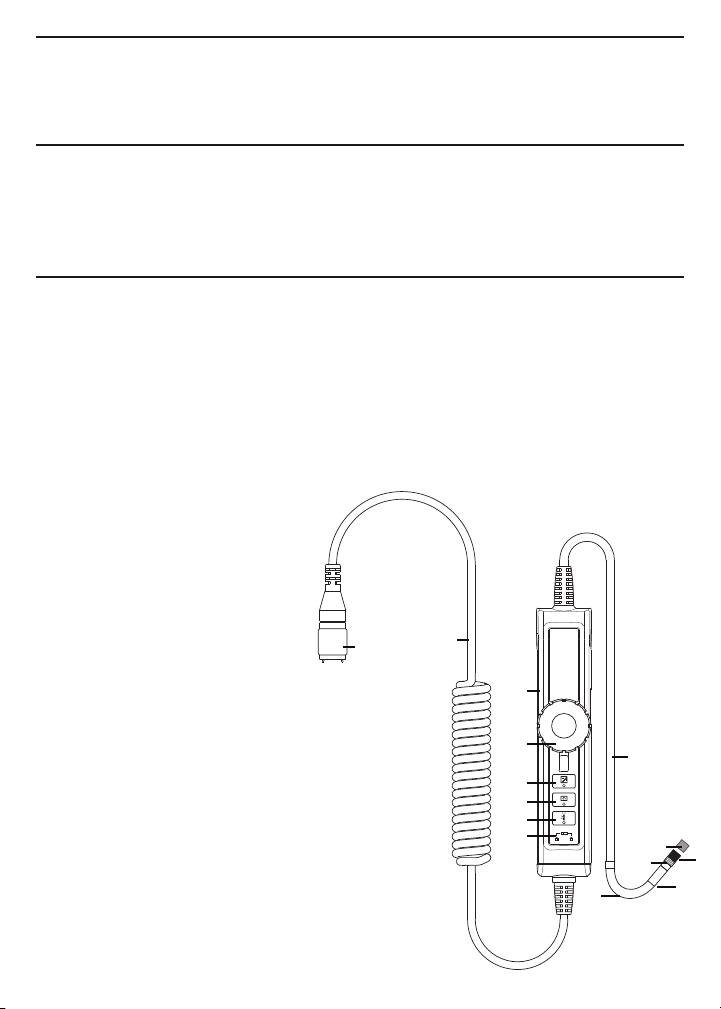
PRODUCT OVERVIEW
Fig. 1 shows the controls and key structures of the P16HPART. Familiarize
yourself with their names and functions before moving on to the Setup
Instructions and Operating Instructions.
Fig. 1. The controls and key structures of the P16HPART
1. Soft metal probe
2. Flexible-obedient, remote-controlled neck
3. Stainless steel camera head with
three forward-facing LEDs and
two side-facing LEDs
4. Stainless steel accessory
alignment ring
5. Black metal thread protector
ring
6. Red rubber protective cap
7. Probe controller body
8. Articulation angle control wheel
with locking lever
9. Light boost button
10. 90° rotation button
11. Anti-reflection button
12. Button lock switch
13. Probe connector cable
14. Probe connector
4
Page 5

SETUP INSTRUCTIONS
6
ATTACH TO BORESCOPE
To attach the probe to a borescope console or to the DCS1800-TR
handle/controller, retract the metal collar of the Probe connector (Fig. 1, Callout
14) to expose the alignment key, which is marked by a dot. Keeping the collar
pulled back, align this dot with the dot on the connector of your borescope
console or handle/ controller and push the two connectors together. To secure
the connection, push the collar forward and turn it clockwise until tight.
OPERATING INSTRUCTIONS
For general guidelines on using the probe as an inspection tool, refer to the
Operating Instructions section of the user’s manual for your borescope or
borescope console. Also see the Operating & Maintenance Tips section of this
manual beginning on p. 10.
Before attempting to articulate the probe,
make sure that the lever below the
articulation angle control wheel
(Fig. 1, Callout 8) is pointing downward.
To bend the probe neck (Fig. 1, Callout 2)
and tip to the left, turn the wheel
clockwise. To bend the probe neck and
tip to the right, turn the wheel
counterclockwise. To lock the wheel
and the probe’s articulation angle,
move the lever below the wheel to the left (see figure above).
To adjust the intensity of the LEDs at the tip of the P16HPART, roll the
thumbwheel on your borescope, borescope console or probe handle/controller
forward or back.
Remember to remove the red rubber protective cap from the tip of the probe
before using it.
5
Page 6

USING THE THREE CONTROL BUTTONS
To boost the intensity of the three LEDs normally providing camera lighting,
press the button. Doing so lights a red LED behind the button and increases
the brightness of video and images, as shown below.
BEFORE BOOST AFTER BOOST
This feature can help you cope with very low-light conditions. When recording
with the boost feature activated, you must hold the probe very steady or your
videos and images will be blurred.
To rotate the probe’s field of view, use the button. Pressing the button
once backlights the button red and rotates the frame clockwise by 90°.
Pressing it a second time rotates the frame by an additional 90°, in effect
turning the original view upside-down. Pressing the button a third time
rotates the field of view yet another 90°. Pressing the button a fourth time
restores the original view and extinguishes the red button backlight.
To remove glare, reflections or spots from the field of view, use the button.
Pressing the button adds a red backlight to it, just like the other two buttons on
the VGA Resolution Articulating Probe controller.
This anti-reflection feature of the P16HPART is most useful for eliminating
reflections of the three forward-facing LEDs in the camera head from shiny
surfaces. Note that pushing the button extinguishes the three forward-facing
LEDs and shifts responsibility for camera lighting to the two side-facing LEDs.
The net effect, as shown below, is a clearer and more-readable image.
WITHOUT ANTI-REFLECTION WITH ANTI-REFLECTION
6
Page 7

You can also use the anti-reflection function to remove glare created by the
P16HPART’s mirrored viewing tip (see the next section of this manual for
installation and alignment instructions). The pair of images below illustrates the
net positive effect.
MIRRORED VIEW MIRRORED VIEW
WITHOUT ANTI-REFLECTION WITH ANTI-REFLECTION
ATTACHING THE MIRRORED VIEWING TIP (OPTIONAL)
The P16HPART comes with a 70° mirrored viewing tip. To attach it to the probe:
1. Pull off the red rubber protective cap (Fig. 1, Callout 6).
2. Unscrew and remove the black metal thread
protector ring (Callout 5), as shown at right.
3. Turn the stainless steel accessory alignment ring
(Callout 4) clockwise to move it away from the
probe tip. Keep turning until the ring can travel
no further.
4. Screw the mirrored viewing tip onto the camera
head (Callout 3) by turning it clockwise, as shown
at right. Keep turning until the viewing tip is as far
from the probe tip as possible. In this position, it
can rotate freely.
5. Press the button to activate the two-side
facing LEDs.
6. Slowly turn the mirrored viewing tip counterclockwise to move it toward
the probe tip. Once the threads of the tip grip the camera head, continue
turning only until the two LEDs are clearly visible through the gap in the
tip’s housing.
7. Secure the tip with the thumb and forefinger of one hand and use your
other hand to turn the alignment ring clockwise. Keep turning the ring until
its leading edge contacts the mirrored viewing tip, locking it in place. The
7
Page 8

pair of figures below illustrate the incorrect (left) and correct (right)
5
✓
orientation of the mirror with respect to the LEDs.
Remove the blue circular protective film from the mirror by pulling on its tab
with a tweezers.
USING THE HOLDING TUBE (OPTIONAL)
Each of the three soft metal VGA articulating probes comes with a steel holding
tube that effectively converts it to a rigid probe of 990mm length and 12mm
diameter (the length and outer diameter of the tube). Use the holding tube
whenever you need to inspect an area above your head (the top of a structure,
for example) or below your knees, or any area that you cannot get closer to
horizontally than 1m away.
To assemble the holding tube, first screw the threaded end of the tube
section with the handle
and locking collar (the
540mm section shown
in the top photo below)
into one side of the
21mm long threaded
coupling. Then screw
the threaded end of the
shorter (450mm long)
section into the other
side of the coupling
(middle photo) to create
a 990mm long hollow
tube (bottom photo) with
a mechanism to lock a
probe inside it.
To insert the probe
into the holding tube:
1. Make sure the lever
8
Page 9

below the articulation angle control wheel
(Fig. 1, Callout 8) on the probe controller is
pointing downward (the unlocked position).
2. Rotate the wheel to straighten the probe tip
(set the articulation angle to 0°).
3. Lock the tip in place by moving the lever
to the left.
4. Make sure the locking collar on the tube
handle is in the unlocked position (see left
photo at right).
5. Feed the probe—articulating tip first—
through the bottom of the tube handle until
the probe’s camera head and articulation
mechanism extend just past the end of the
tube (see drawing at right).
6. Lock the probe in place by moving the collar
to the locked position (see right photo above)
UNLOCKED LOCKED
SPECIFICATIONS
Probe Type Soft metal
Probe Length/Articulation Angle P16HPART: 1m (3.3 ft.)/±155°
P16HP2ART: 2m (6.6 ft.)/±145°
P16HP3ART: 3m (9.8 ft.)/±135°
Camera Head Diameter, Type 0.23 in. (6mm), Stainless steel
Camera Head Diameter 0.26 in. (6.5mm)
with Thread Protector
Camera Head Length 0.9 in. (23mm)
Camera Resolution VGA (640 x 480 pixels)
Camera Depth of Field 0.25 to 12 in. (6.4 to 300mm)
Camera Field of View 87° (diagonal)
Camera Lighting 3 forward-facing LEDs
+ 2 side-facing LEDs
9
Page 10

Operating Temperature -4° to 140°F (-20° to 60°C)
9
.
1 to 2 in.
(25 to 50mm) from tip
2
in. (50mm)
or more from tip
9
.
1 to 2 in.
(25 to 50mm) from tip
2 in. (50mm)
or more from tip
Dimensions of Probe Controller 5.47 x 1.38 x 1.26 in. (139 x 35 x 32mm)
Weight of Controller 7.76 oz. (220g)
OPERATING & MAINTENANCE TIPS
The probe is flexible to make it easy for you to
inspect hard-to-reach areas. Never insert or bend it
by force, and never over-bend any part of the
probe. Specifically:
• Do not bend the last 1 to 2 inches (25 to 50mm)
of the probe by more than 70°
• Do not bend the probe at any other point by
more than 90°
• The probe’s neck is a particularly sensitive area.
Never apply heavy weights or forces to the neck.
Never try to bend the neck by hand; use only the
control wheel. Before storing the probe,
straighten the neck.
To avoid permanently damaging the delicate wires and fiber optic cables inside
the probe, never curl it into a circle with a diameter of less than 6 in. (150mm).
Never use the probe or camera head to modify surroundings or to clear
pathways or clogged areas.
DO NOT try to rotate the articulation angle control wheel beyond its limits.
The camera head, LEDs and thread protector ring are waterproof, but not
acid-proof or fire-proof. Do not touch acidic, corrosive or hot materials or they
will ruin the head.
Cover the camera-tipped end of the probe with the protective red rubber cap
when not using it. Remember to remove the cap from the tip of the probe
before using it again.
Unless you wish to install the 70° mirrored viewing tip, do not remove the
thread protector ring (Fig. 1, Callout 5). Never use the probe without attaching
either an accessory or the thread protector ring to it.
Never use the probe as a hammer or hook.
10
Page 11

When inspecting a vehicle, shut off the engine. Metal and liquid under the hood
may be hot. Do not get hot oil or gas on the camera head.
If condensation forms inside the camera lens, let it evaporate before using the
probe again.
Because the VGA Resolution Probe has three extra-bright LEDs that require
more power than the LEDs of General’s QVGA (320 x 240 pixel) resolution
probes, using the P16HPART will drain the batteries of your borescope more
quickly. You will have to recharge your borescope more often.
Do not try to disassemble any part of the probe. Doing so creates an electrical
hazard, could damage the probe, and voids the limited warranty.
Do not use any corrosive liquid—such as alcohol—to clean the probe body or
camera head. Use a cotton swab and a mild fluid detergent to clean the body
and head.
WARRANTY INFORMATION
General Tools & Instruments’ (General’s) P16HPART, P16HP2ART and
P16HP3ART VGA Resolution Articulating Probes are warranted to the original
purchaser to be free from defects in material and workmanship for a period
of one year. Subject to certain restrictions, General will repair or replace this
instrument if, after examination, the company determines it to be defective
in material or workmanship. The warranty period begins on the date of
purchase. You are encouraged to register your product online. General
will extend your warranty an additional 60 days if you register at
www.generaltools.com/ProductRegistry.
This warranty does not apply to damages that General determines to be from
an attempted repair by non-authorized personnel or misuse, alterations, normal
wear and tear, or accidental damage. The defective unit must be returned to
General Tools & Instruments or to a General-authorized service center, freight
prepaid and insured.
Acceptance of the exclusive repair and replacement remedies described herein
is a condition of the contract for purchase of this product. In no event shall
General be liable for any incidental, special, consequential or punitive damages,
or for any cost, attorneys’ fees, expenses, or losses alleged to be a
consequence of damage due to failure of, or defect in any product including,
but not limited to, any claims for loss of profits.
Register now at www.generaltools.com/ProductRegistry to receive a 60-day
extension to your warranty.
11
Page 12

RETURN FOR REPAIR POLICY
General Tools & Instruments
General Tools & Instruments
GeneralToolsNYC
Every effort has been made to provide you with a reliable product of superior
quality. However, in the event your instrument requires repair, please contact
our Customer Service to obtain an RGA (Return Goods Authorization) number
before forwarding the unit via prepaid freight to the attention of our Service
Center at this address:
Remember to include a copy of your proof of purchase, your return address,
and your phone number and/or e-mail address.
99 Washington Street
Melrose, MA 02176
Phone 781-665-1400
Toll Free 1-800-517-8431
Visit us at www.TestEquipmentDepot.com
12
Specifications subject to change without notice
©2014 GENERAL TOOLS & INSTRUMENTS
NOTICE - WE ARE NOT RESPONSIBLE FOR TYPOGRAPHICAL ERRORS.
MAN# P16HPART/P16HP2ART/P16HP3ART
10/09/14
 Loading...