

Page 1

WIRELESS RECORDING
VIDEO INSPECTION SYSTEM
with 5-INCH LCD
USER’S MANUAL
DCS500
99 Washington Street
Melrose, MA 02176
Phone 781-665-1400
Toll Free 1-800-517-8431
Visit us at www.TestEquipmentDepot.com
Please read this manual carefully and thoroughly before using this product.
Page 2

TABLE OF CONTENTS
Key Features . . . . . . . . . . . . . . . . . . . . . . . . . . . . . . . . . . . . . . . . . . . . . . . . . 3
Safety Instructions . . . . . . . . . . . . . . . . . . . . . . . . . . . . . . . . . . . . . . . . . . . . 3
What’s in the Package . . . . . . . . . . . . . . . . . . . . . . . . . . . . . . . . . . . . . . . . . . 4
Product Overview . . . . . . . . . . . . . . . . . . . . . . . . . . . . . . . . . . . . . . . . . . 4 –6
Setup Instructions . . . . . . . . . . . . . . . . . . . . . . . . . . . . . . . . . . . . . . . . . . 6 –8
Attach Probe . . . . . . . . . . . . . . . . . . . . . . . . . . . . . . . . . . . . . . . . . . 6
Charge Batteries . . . . . . . . . . . . . . . . . . . . . . . . . . . . . . . . . . . . . . . 7
Install SD Card (Optional) . . . . . . . . . . . . . . . . . . . . . . . . . . . . . . . . 7
Set Auto Power Off Interval (Optional) . . . . . . . . . . . . . . . . . . . 7 –8
Install Thread Protector or Probe Tip Accessory . . . . . . . . . . . . . . 8
Operating Instructions . . . . . . . . . . . . . . . . . . . . . . . . . . . . . . . . . . . . . .8 – 20
Viewing Live Video on the Monitor . . . . . . . . . . . . . . . . . . . . . . . . . 9
Viewing Live Video on a TV Monitor . . . . . . . . . . . . . . . . . . . . . . . 10
Viewing Live Video on a PC . . . . . . . . . . . . . . . . . . . . . . . . . . 10 – 11
Recording and Viewing Videos and Photos . . . . . . . . . . . . . 11 – 14
Taking Pictures and Recording Videos . . . . . . . .11 – 12
Viewing Saved Videos and Pictures . . . . . . . . . . 12 – 14
Navigating the Five Menus . . . . . . . . . . . . . . . . . . . . . . . . . . 14 – 17
Installing and Using ScopeView . . . . . . . . . . . . . . . . . . . . . . 18 – 20
Installation Instructions . . . . . . . . . . . . . . . . . . . . . . . 18
Using ScopeView . . . . . . . . . . . . . . . . . . . . . . . . . 19 – 20
Specifications . . . . . . . . . . . . . . . . . . . . . . . . . . . . . . . . . . . . . . . . . . . 20 – 21
Maintenance Tips . . . . . . . . . . . . . . . . . . . . . . . . . . . . . . . . . . . . . . . . 21 – 22
Warranty Information . . . . . . . . . . . . . . . . . . . . . . . . . . . . . . . . . . . . . . . . . 22
Return for Repair Policy . . . . . . . . . . . . . . . . . . . . . . . . . . . . . . . . . . . . . . . 23
2
Page 3

KEY FEATURES
• Monitor with 5 in. (127mm) diagonal color LCD can be detached from pistol grip and probe
to receive video wirelessly
• Grip and monitor are IP54 splash-proof
• Grip attaches to 1m long x 9mm (0.35 in.) diameter flexible-obedient camera-tipped probe
with IP67 rating and depth of field of 1 in. to 10 ft. (25mm to 3m). Longer and thinner
probes are available.
• Squeezing trigger on pistol grip manually records video clips and still photos onto included
2GB MicroSD card or in integral 128MByte flash memory. Videos and photos can also be
captured automatically in response to motion in the field of view.
• Monitor has 1 to 4X zoom function, adjustable Auto Power Off trigger, magnets on back for
attaching to metal surfaces, and built-in microphone and speaker for recording and playing
back voice-annotated video clips
• ScopeView software and USB cable for organizing and viewing live and recorded photos
and videos on any Windows PC
• Streams video onto Internet through optional RCV100 USB wireless PC dongle
• Monitor and grip powered by separate rechargeable Li-ion batteries
• TV Out jack and A/V cable for viewing live video on NTSC or PAL TV monitor
• Four probe tip accessories (magnetic pickup, pickup hook. 45° mirror, thread protector
ring)
• Custom hard plastic carrying case
• Choice of five menu languages
• 1 Year warranty
SAFETY INSTRUCTIONS
• Do not use the probe to inspect environments known or suspected to contain exposed
electrical wiring.
• Do not use the system in the presence of flammable or explosive gases.
• Read and understand all of the instructions in this manual before using the system.
• Stay alert, watch what you are doing, and use common sense. A moment of distraction can
result in serious personal injury.
• Do not over-reach. Keep proper footing and balance at all times, especially where water is
underfoot.
• Always use protective eyewear. A dust mask, non-skid safety shoes, a hard hat or hearing
protection may also be appropriate for certain inspection environments and tasks.
• Do not use the system to perform medical inspections.
3
Page 4

WHAT’S IN THE PACKAGE
The DCS500 and its accessories come in a custom molded plastic case. The instrument itself has
two components: a pistol grip attached to a camera-tipped probe, and a wireless console with an
LCD, multiple I/O jacks and a MicroSD card socket. Also in the case are:
• Four probe tip accessories (a 45° mirror, a pickup hook, a magnetic pickup and a thread
protector ring)
• A cable with a standard-size USB plug at one end and a MicroUSB plug at the other
• An A/V cable with a mini-stereo plug at one end and two RCA plugs at the other
• A signal cable with a mini-stereo plug at both ends
• A mini-disc containing: 1) the ScopeView software program for viewing and organizing
video clips and photos captured by the DCS500; 2) drivers for enabling ScopeView to run
on PCs with various versions of Windows; 3) a soft copy of this user’s manual in pdf format
• An AC adaptor/charger with a 9VDC, center-positive output plug
• A hard copy of this user’s manual • 2GB MicroSD memory card
PRODUCT OVERVIEW
Fig. 1 shows and names all of the accessories that come with the DCS500. Fig. 2 shows the
names and locations of all the controls, jacks, ports and structures of the unit. Table 1 details
how the function of each front-panel button changes with the DCS500’s operating mode.
Familiarize yourself with the labels, positions and functions of all buttons and connectors before
moving on to the Setup Instructions and Operating Instructions.
1. 9mm diameter camera-tipped probe
2. Detachable wireless monitor
3. Wireless grip
4. Pickup hook
5. 45° mirrored viewing tip
6. Magnetic pickup
7. Thread protector ring
8. Mini-CD containing ScopeView software
and instructions, Windows drivers, and soft
copy of this user’s manual in pdf format
9. AC charger with dual DC
output cables
10. A/V cable for connecting to TV
11. USB cable for interfacing to PC
12. Signal cable for connecting grip
and probe to monitor
13. 2GB MicroSD card
Fig. 1. The DCS500 and all
included accessories
13
4
Page 5

Fig. 2. The DCS500’s controls, connectors and
A. Lens cap
B. Camera head
C. 1m long, 9mm diameter
flexible-obedient probe
D. Probe connector
E. LCD
F. Grip “power on” LED
G. Grip and monitor power on/off ( and ) buttons
H. + button. Increases brightness of
camera lighting
I. – button. Decreases brightness of
camera lighting
J. Grip and monitor battery charge status LEDs
K. Microphone
L. Grip and monitor I/O panel rubber flaps
M. multi-function button (see Table 1)
N. multi-function button (see Table 1)
O. MENU multi-function button (see Table 1)
P. multi-function button (see Table 1)
Q. multi-function button (see Table 1)
R. 4:3/ESC multi-function button (see Table 1)
AA
physical structures
S. Threaded tripod mounting hole
T. Speaker
U. DC9V IN jack
V. LINE IN and LINE OUT jacks
for connecting monitor and grip
W. TV OUT jack
X. MicroUSB jack
Y. MicroSD card socket
Z. RESET button
AA. Magnets
5
Page 6

Table 1. The DCS500’s multi-function buttons
SETUP INSTRUCTIONS
ATTACH PROBE
The 9mm probe must be attached to the pistol grip for the system to function. To attach the
probe:
1) Make sure the grip is not powered on. Stray current
from an energized grip might find a path into the wrong
pins of the probe during the connection process and
damage the probe.
2) Align the key on the probe connector with the flat on the
grip’s probe connector (see photo at right).
3) Push the two connectors together until they mate.
4) Hand-tighten the connection by rotating the knurled collar of the grip connector in the
direction opposite the REMOVE arrow.
6
Page 7

CHARGE BATTERIES
The Li-ion batteries in the grip and console must both be charged (or charging) for the system to
be ready for use.
Inside the DCS500 case is an AC adaptor/charger with two output cables (Fig. 1, Callout 9) that
makes it possible to charge both batteries at the same time. To do so,
1) After lifting the black rubber flaps protecting the I/O panels
of the grip and monitor, insert the cylindrical plug at the end
of one of the cables into the DC9V jack at the bottom of the
grip, and the plug at the end of the other cable into the
DC9V jack on the right side of the monitor. In Fig. 2, both
flaps are identified by the callout “L”, while both jacks are
identified by the callout “U”.
2) Plug the AC adaptor into a 110VAC outlet.
While the monitor and grip are charging, the two LEDs that indicate
battery charge level (Fig. 2, Callout J) will glow red. Once the
batteries have been charged enough to power the grip/probe and
monitor on their own, the LEDs will change color to green. Once
both LEDs are glowing green, unplug the charging cables and the
AC adaptor.
INSTALL SD CARD (OPTIONAL)
To install the included 2GB MicroSD memory card (or another card of up to 16GB capacity) in
the DCS500 console, lift the black rubber flap on its right side (Fig. 2, Callout L). Grasp the card
between your thumb and index finger with the contacts facing up. Push the card into the socket
(Callout Y) until you feel the card spring back and hear a click. If the card has been inserted
properly, an icon of an SD card will replace the “M” icon in the upper right corner of the LCD.
Once the monitor detects the presence of an SD card, it will store video clips and photos on the
card, rather than in internal memory.
SET AUTO POWER OFF INTERVAL (OPTIONAL)
By default, the Auto Power Off function of the DCS500 monitor is disabled. To avoid unnecessarily
draining the monitor’s battery (which would make the entire system unavailable for use), General
strongly recommends that you reset the Auto Power Off interval from “Never” to 5, 10 or 20
minutes of inactivity at the front-panel buttons. Having the DCS500 occasionally power off on its
own is only a minor inconvenience because the unit can be restarted in less than 5 seconds.
To change the Auto Power Off interval:
1. Press the MENU button.
2. Press the button (Fig. 2, Callout Q) twice to open the Set Time/Date menu.
3. Press the button (Fig. 2, Callout P) three times to scroll down three lines to Auto Off
Time.
4. Press the MENU button to open the Auto Off Time submenu.
7
Page 8

5. Press the button to scroll down to and highlight the 5 Minutes, 15 Minutes or
30 Minutes line.
6. Press the MENU button to save your selection. Doing so will remove the check mark next
to Never and add a check mark next to your selection, confirming that it has been saved.
7. Press the 4:3/ESC button (Fig. 2, Callout R) twice to return to Preview (live video) mode.
INSTALL THREAD PROTECTOR OR PROBE TIP ACCESSORY
The DCS500 comes with four accessories (Fig. 1, Callouts 4 to 7) that screw on to the cameratipped end of the 9mm probe. Each accessory has a specific purpose:
• The 45° mirror lets the probe see around corners.
• The pickup hook lets you retrieve otherwise inaccessible items seen by the probe—
for example, a wedding ring accidentally dropped down a sink drain.
• The magnetic hook lets you retrieve lost or dropped metal objects—nuts and bolts,
for example—located by the probe.
• The thread protector ring
Attach the thread protector before you use the DCS500 for the first time. Remove it before
attaching any of the three other accessories. Reattach the thread protector after removing an
accessory. Never expose the threads of the probe tip to the dangers of an inspection session.
OPERATING INSTRUCTIONS
The DCS500 can be operated wirelessly (with the monitor detached from the grip and probe) or
with the two components physically connected.
To attach the monitor to the grip, position the two slots on the
back of the monitor above the two tracks on the back of the grip
and carefully slide the monitor down (see figure at right) until you
hear a click.
To detach the monitor, carefully slide it up along the tracks of
the grip.
When using the system in wireless mode in an electrically noisy
environment, video captured by the probe may appear “streaky” on
the DCS500 monitor or on a TV monitor or PC screen attached to the
DCS500 monitor. To remedy the problem, try using the included signal
cable (Fig. 1, Callout 12) to electrically interconnect the grip and
monitor. The mini-stereo plugs at the ends of the signal cable fit the
LINE IN jack of the monitor and the LINE OUT jack of the grip.
On Fig. 2, both jacks are identified by the callout “V”.
8
Page 9

You have three options for viewing live video captured by the DCS500’s camera-tipped probe:
1. View it on the monitor’s 5 in. LCD.
2. View it on a larger TV monitor.
3. View it on a desktop or laptop PC after connecting the PC to the DCS500 with the supplied
USB cable. This option requires installing the ScopeView photo/video management/display
application and an accompanying driver for the DCS500 from the mini-disc included in
your system. Instructions for installing and using ScopeView can be found on p. 18 of
this manual.
VIEWING LIVE VIDEO ON THE MONITOR
Before using the DCS500 for the first time, remove the plastic film protecting the LCD.
To power on the unit, press and hold the button on the grip and the button on the
console (Fig. 1, Callout G) for at least 3 seconds each. The LCD will illuminate and begin showing
real-time video from the camera at the tip of the probe. By default, a date and time will be
displayed on the bottom of the screen (see p. 16 to learn how to set the date and time). An icon
representing the level of battery charge will appear left of center at the top of the screen. If you
have inserted a MicroSD card, an “SD” icon will appear at the top right of the screen. If you have
not inserted an SD card, this position will show the letter “M” to indicate that the only memory
available for storing photos and video clips is the integral 128MByte flash memory.
To increase the brightness of the display, press the + button (Fig. 2, Callout H) on the grip. To
decrease brightness, press the – button (Fig. 2, Callout I). In a brightly lit room, changing the
intensity of the two LEDs at the tip of the probe has only a small effect on the brightness of video
on the screen. The on-screen impact of changing brightness is more pronounced in dark
environments.
To zoom in and out on video, use the and buttons. Each press of each button
increases or decreases the zoom level by a factor of 50% relative to actual (1X) size. Five zoom
levels are available: 1.5X, 2.0X, 2.5X, 3.0X, 3.5X and 4.0X, and each appears at the bottom left of
the LCD when selected. From the 4.0X level, you cannot return to normal-size viewing without
“backing out” of the zoom function by pressing the button six times.
The 9mm diameter probe supplied with the DCS500 is “flexible-obedient”, which means that you
can bend and maneuver it into various positions to aim at different targets and it will hold its
shape. In practice, professionals usually insert a flexible-obedient probe head-on into an orifice (a
hole in wall or an engine’s cylinder) or a hard-to-reach or hard-to-see area as a first step. They
then pull the probe out and adjust its bend one or more times until the camera in the tip is
pointing directly at the target or area of interest. With the probe inserted, you can twirl it until
video appears right-side up, but in many cases you cannot change the probe’s angle of approach
very much. You can, however, change the probe’s viewing angle by 90° by attaching the included
45° mirror accessory to the tip of the probe. See p. 8 for attachment instructions.
Before using the system, carefully read the Maintenance Tips section of this manual on pages 21
and 22 to understand how to use the probe properly and avoid using it improperly. To protect the
camera-tipped end of the probe, reinstall the black rubber lens cap after each inspection session.
9
Page 10

VIEWING LIVE VIDEO ON A TV MONITOR
To view live video being captured by the DCS500’s camera-tipped probe on an NTSC- or PALformat television or TV monitor:
1. Power off the DCS500 monitor by pressing and holding the button.
2. Lift the black rubber flap at the right of the monitor.
3. Insert the mini-stereo plug at one end of the supplied AV cable (Fig. 1, Callout 10) into the
TV OUT jack on the right side of the monitor (Fig. 2, Callout W).
4. Insert the yellow RCA plug at the other end of the cable into the television’s “Video In”
jack.
5. Power the DCS500 monitor on by pressing and holding the button.
6. If you are connecting to a PAL-format TV, open the Advanced Settings menu and change
the TV Output Standard setting from NTSC to PAL (see p. 15 for instructions)
After you make the connection, you can watch live video on the DCS500 and the TV at the same
time. Note: Live video exiting through the TV OUT jack can be zoomed in and out using the
and buttons.
VIEWING LIVE VIDEO ON A PC
To view live video being captured by the DCS500’s probe on a PC, you must:
1. Install the ScopeView application and a Windows driver from the mini-disc included
with your system by following the instructions beginning on p. 18 of this manual.
2. Power off the DCS500 by pressing and holding the button.
3. Lift the black rubber flap on the right side of the monitor.
4. Insert the MicroUSB plug at one end of the supplied USB cable (Fig. 1, Callout 11) into the
MicroUSB jack on the right side of the monitor (Fig. 2, Callout X).
5. Insert the standard-size USB plug at the other end of the cable into a USB port of your PC.
6. Power on the DCS500 on by pressing and holding the button. With the USB cable
plugged in, powering on the DCS500 on will not cause live video to appear on the monitor.
The monitor will show the familiar “waiting” hourglass, and it will continue to do so until
you take the following three steps.
7. Open ScopeView.
8. Deselect “Integrated Camera” and select “Instant USB Camera” using the pulldown at the
left of the toolbar below the main menu (see screen shot on next page).
9. Click the blue “Connect” button at the right of the pulldown. Your PC’s screen will then
begin showing the same live video feed from the DCS500’s camera-tipped probe as the
unit’s monitor.
After you make the connection, you can watch live video on the DCS500 and your PC at the same
time. Note: Live video exiting through the USB jack cannot be zoomed in and out using the
and buttons.
10
Page 11

RECORDING AND VIEWING VIDEOS AND PHOTOS
In addition to capturing and manipulating real-time video, the DCS500 can document—via
videos and photos—what the camera at the tip of its probe “sees.” Squeezing the yellow trigger
on the pistol grip briefly (or pressing the front-panel button) takes a picture of the probe’s
field of view and stores it as a .jpg file in the monitor’s 128Mbyte flash memory or on an installed
MicroSD card. Similarly, squeezing and holding the trigger (or pressing the front-panel
button) causes the DCS500 to begin recording an .avi video clip of the probe’s field of view onto
the MicroSD memory card (if installed) or into the unit’s flash memory.
Other front-panel buttons are used to view (play back) recorded images and videos on the
monitor’s 5 in. LCD and to browse their files and folders. Alternatively, recorded images and
videos can be viewed on a larger TV monitor, either by ejecting the SD card and plugging it into a
laptop or desktop PC (directly or through an SD card reader), or by connecting the DCS500 to a
PC via the supplied USB cable.
Taking Pictures and Recording Videos
Before recording videos and still images, you should install a MicroSD memory card (see the
Setup Instructions section) and set the current date and time (see p. 16). The DCS500 provides a
128Mbyte flash memory for recording without an SD card, but the flash memory’s relatively
small capacity severely limits video recording time. At the DCS500’s default D1 (720 x 480 pixel)
recording resolution, the flash memory’s entire capacity will be used up by less than 4 minutes of
video (recorded at 30Mbytes/sec).
To take a picture, make sure the DCS500 is in Preview (Live) viewing mode, with the current
date and running clock at the bottom of the LCD. Squeeze the trigger briefly or press thel
button. Within less than a second, the monitor will “chirp” once and a white icon will appear
briefly in the center of the LCD to indicate that a picture was taken.
To begin recording a video clip, squeeze and hold the trigger or press the button on the
monitor. This will cause 1) the monitor to chirp twice, 2) the current date and time at the bottom
of the screen to change color from white to yellow, 3) the battery charge indicator at the top of
11
Page 12

the LCD to disappear, and 4) a white count-up timer to appear at the upper right of the display
above a flashing red •REC icon. The timer will count up from 00:00:00 to indicate the duration of
the clip already recorded.
To stop recording the video clip, press the button again. This will cause 1) the monitor to
chirp twice, 2) the timer and the •REC icon to disappear from the top right of the display and 3)
the battery charge indicator to reappear. It will also return the unit to operation in Preview mode.
You cannot pause the recording of a video. You must use the button to stop recording and
start again, creating a new file in the process. The button is the only button that is
responsive during the recording of a video.
Viewing Saved Videos and Pictures
You have four options for viewing (playing back) videos you have recorded and pictures you have
taken:
1. View them on the DCS500’s 5 in. monitor.
2. View them on a larger TV monitor.
3. View them on a desktop or laptop PC by ejecting the MicroSD memory card from the
DCS500 and plugging it into the PC.
4. View them on a desktop or laptop PC by connecting it to the DCS500 with the supplied
USB cable. You can view the media using a) standard computer photo and video viewing
applications and video applications like Windows Photo Viewer and Windows Media Player
or b) the ScopeView photo/video management/display application included on the minidisc included with your system. Instructions for installing ScopeView and the
accompanying driver for the DCS500 from the mini-disc can be found on p. 18 of this
manual.
The third and fourth options offer additional benefits. As you view your saved inspection videos
and pictures, you can copy them to your PC. Once the videos and images are in your computer,
you can share them as attachments to e-mails to others experienced at spotting and diagnosing
problems in your field. In addition, any videos and pictures that you have copied to your PC can
be deleted from the DCS500’s flash memory and SD card, freeing up space for future photo
captures and video recordings.
To view saved pictures and videos (and hear voice annotations of video clips) on the DCS500’s
monitor, power on the unit and press the button briefly to switch from Preview mode to
Playback mode. In the switch to Playback mode:
• The battery charge indicator on the top line of the display is replaced by an icon of a
camera or a film strip, corresponding to the type of recording made most recently.
• The screen switches from showing “live” video to showing a static image that is either a
saved image or the first frame of a saved video.
• The current date and running time clock at the bottom of the screen are replaced by three
pieces of information about the static image on screen: 1) The name of the subfolder in
which the image or video file is stored; 2) The image or video’s file name; and 3) The date
and time of its capture.
12
Page 13

To view saved videos and pictures on a larger TV monitor, you must first power off the unit
by pressing and holding the button. Then:
1. Lift up the black rubber flap at the right of the LCD.
2. Insert the mini-plug end of the supplied video cable into the TV OUT jack on the right side
of the monitor (Fig. 2, Callout W).
3. Insert the yellow RCA plug at the other end of the cable into the television’s “Video In”
jack.
4. Insert the adjacent white RCA plug into the “Audio In” jack of the left or right channel.
5. Power the DCS500 back on by pressing and holding the button again.
After you make the connection, you can view recorded video clips and pictures on the DCS500
and the TV at the same time. You can also hear any voice annotations added to video clips.
To play a saved video clip, press the button. Once the video starts playing, a running clock
will appear at the upper right of the display to track the playback position. A white (pause) icon
will also appear, at upper left. To pause playback of the video clip, press the button (which
executes the 왖 Pause command indicated at the bottom of the display). Pressing the button
will cause the white pause icon to change to a white왘(play) icon. To resume playing the
video, press the button again (to execute the왖Play function indicated at the bottom of the
screen). This will cause the pause icon to reappear. To stop the video clip being played, press
the button (which executes the왔Stop command indicated at the bottom of the display).
To view saved videos and pictures on a PC directly from the MicroSD memory card, open
the flap on the side of the monitor. Eject the memory card by firmly pushing on it with a fingertip
until the card springs back and you hear a click. If you are in Preview mode, the SD card icon at
the upper right of the display will be replaced by an “M” icon. If you are in Playback mode, the
DCS500 will switch to Preview mode.
Many newer PCs (and flat-screen TVs) are equipped with a slot for a standard-size SD card. If
you want to plug your MicroSD card into such a slot, you will need a MicroSD to SD card adapter.
They are widely available for $5 or less from most consumer electronics retailers.
Plug the MicroSD card with your recorded inspection videos and picture into the adapter, and
then plug the adapter into your PC’s SD card slot.
If you have configured your PC to automatically play external media, plugging in the adapter will
open an AutoPlay dialogue box that verifies insertion of an “SD card”. Clicking on “Open folder to
view files” reveals one folder, named “YCKC”, which contains all of the videos and pictures stored
on the card. Double-click on the YCKC folder icon to view the subfolders containing the individual
video and picture files. The subfolders’ names use the YYMMDD00 format to reflect the date on
which files were added to them. For example, a subfolder titled “14033100” would contain media
recorded on March 31, 2014. Video clips are in .AVI format and pictures are in .JPG format.
To use ScopeView to view saved videos and pictures on a PC via a USB connection, follow
the instructions for Viewing Live Video on a PC on p. 10.
13
Page 14
To use standard PC applications to view saved videos and pictures on a PC via a USB
connection:
1. Install the ScopeView application and a Windows driver from the mini-disc included
with your system by following the instructions beginning on p. 18 of this manual.
2. Lift up the black rubber flap at the right of the LCD.
3. Without opening ScopeView or powering on the DCS500, insert the MicroUSB plug
end of the supplied USB cable into the MicroUSB jack on the right side of the monitor
(Fig. 2, Callout X).
4. Insert the standard-size USB plug at the other end of the cable into a USB port of your PC.
If you have configured your PC to automatically play external media, plugging in the USB cable
will open an AutoPlay box that verifies connection of a “Removable Disk.” It will also cause the
DCS500’s LCD to turn all blue, with the words “USB Disk Mode” overlaid in white.
Clicking on “Open folder to view files” reveals one folder, named “YCKC”, which contains all of
the videos and pictures stored on the card. Double-click on the YCKC folder icon to view the
subfolders containing the individual video and picture files. The subfolders’ names use the
YYMMDD00 format to reflect the date on which files were added to them. For example, a
subfolder named “14033100” would contain media recorded on March 31, 2014. Video clips are
in .AVI format and pictures are in .JPG format.
NAVIGATING THE FIVE MENUS
The DCS500 provides five menus which you can use to change many of the system’s operating
parameters and display characteristics.
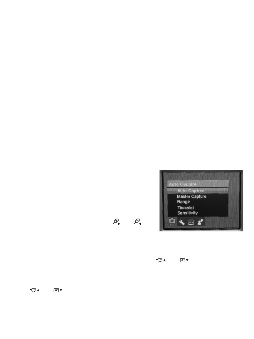
Four of the five menus become accessible by pressing the
MENU button with the DCS500 in Preview mode. Press the
button, and the first menu to appear is the Auto Capture
menu. Below it on-screen, from left to right, will be the icons
of the Advanced Settings, Set Time/Date and Language
menus (see screen shot at right).
To choose among the four menus, use the and
buttons as “move right” and “move left” buttons, respectively.
All four menus are navigated in identical fashion. When a menu is open, its name is displayed in
an orange banner over the names of submenus on a black background. Each submenu lets you
choose between or among two or more options for that functional category.
To open any submenu, first navigate to its line by using the and buttons as “move
up” and “move down” buttons, respectively. Navigating to a submenu changes the background
color of its line from back to orange. Then press the MENU button to select the submenu.
To select any of the available options inside a submenu, use the same two-step procedure. First
use the and buttons to navigate to the option’s line, changing its background color to
orange. Then press the MENU button to select the desired option. The only difference between
selecting a submenu and selecting an option is the presence of a white check mark next to the
option that is currently in force. Note that pressing the MENU button to change any function or
parameter moves the check mark next to the new option to be enabled or activated.
14
Page 15

The The Auto Capture menu
Submenu name Options Instructions/Comments
Auto Capture On Select On to activate motion sensing
Off (default)
Master Capture Photo 1 (default) Selects the camera action to be taken automatically in
Photo 3 response to a motion event. Photo 1 refers to one
5 Second Movie photo and Photo 3 refers to three photos.
10 Second Movie
Range 1/1 (default) Selects the fraction of screen area in which motion will
1/4 be sensed and acted on. Selecting a 1/4 area generates
an on-screen green box that can be moved up, down,
left and right by the ,, and buttons.
After moving the box, press the MENU button to save
its position.
Timeslot 1s Selects the minimum duration of a motion event
3s (default) needed to trigger an Auto Capture camera action
5s
Sensitivity Low Selects motion-sensing sensitivity to object size, color
Medium and speed. If operating at the default High sensitivity
High (default) level triggers too many unwanted motion events,
reduce the sensitivity to Medium or Low
The Advanced Settings menu
Submenu name Options Instructions/Comments
Movie Resolution QVGA Select QVGA to record video clips with 320 x 240 pixel
D1 (default) resolution. Select D1 to record at 720 x 480 pixel
resolution. D1 files offer higher video quality but take
up more storage space.
File OverWrite On Selecting On allows new files to overwrite old files
Off (default) when installed memory is close to full capacity.
Selecting Off disallows overwriting, but may prevent
storage of new files.
TV Output Standard NTSC (default) Choose NTSC in North America, Central America,
PAL Japan, South Korea and Taiwan. Choose PAL in Europe,
Africa and much of Asia and Africa
LCD Brightness Low Adjusts brightness to ambient conditions
Normal LevelNormal Level (default)
Normal Level+
High
Format Yes Formatting a MicroSD card erases its entire contents
No (default)
15
Page 16

Set to Default Yes Select Yes to reset all settings to their default value
No (default)
Disk Information N/A Displays the total capacity of installed memory—
128Mbyte internal + MicroSD card capacity (if
installed)—and how much of that capacity is free
(available)
Firmware version N/A Displays the Version Nos. of the unit’s firmware and
user interface
The Set Time/Date menu
Submenu name Options Instructions/Comments
Set Time/Date Current date A) To enter the current date in the default format of
Current time YY/MM/DD (year, month, day): 1) Press the or
Date format button to increase or decrease the YY value. Then press
the button to advance to and highlight the MM
field; 2) Press the or
decrease the MM value. Then press the button to
advance to and highlight the DD field; 3) Press the
or button to increase or decrease the DD value.
Then press the button to advance to and highlight
the hours field on the next line.
B) To set the current time: 1) Press the or
button to increase or decrease the value in the hours
field to match the current hour in 24-hour (military
time) format. Then press the button to advance to
and highlight the minutes field; 2) Press the or
button to increase or decrease the minutes value
to match the current value. Then press the button
to advance to and highlight the seconds field; 3) Press
the or button to increase or decrease the
seconds value. Then press the button to advance
to and highlight the date format line below.
C) To change the date format (optional): 1) Press the
or button repeatedly to cycle through the
three options: YY/MM/DD (default), MM/DD/YY and
DD/MM/YY. 2) Select your preferred format. Whether or
not you change the date format, you must press the
MENU button to save all of your settings and return to
the Set Time/Date menu one level above.
(Hint: Pressing the button allows you to return to
any field and change its value before you press the
MENU button to save that value and your other
settings.)
button to increase or
16
Page 17

Photo TimeStamp On (default) Select On to record the date and time when a photo is
Off saved. This information becomes part of the photo’s file
and is overlaid on displays of the image.
Selecting Off prevents addition of date and time stamps
to photo files.
After making your selection, press the 4:3/ESC button
to save it and return to the Set Time/Date menu.
Movie TimeStamp On (default) Select On to record the date and time when a movie file
Off is saved. This information becomes part of the video’s
file and is overlaid on playbacks of the video.
Selecting Off prevents addition of date and time stamps
to video files.
After making your selection, press the 4:3/ESC button
to save it and return to the Set Time/Date menu.
Auto Off Time Never (default) Determines when the unit will power off automatically
5 minutes following a period of time when no front-panel buttons
15 minutes are pressed. Select 5 minutes to maximize battery life.
30 minutes After making your selection, press the 4:3/ESC button
to save it and return to the Set Time/Date menu. Press
the 4:3/ESC button again to return to Preview mode.
The Playback menu
Submenu name Options Instructions/Comments
File Delete Single (default) Selecting any option by pressing the MENU button
All Files in Folder opens a “Delete Yes or No” screen. Choose Yes to
All delete either: the Single movie or photo file currently
on-screen; All Files in its Folder; or All files on the
MicroSD memory card.
Format Yes Formatting a MicroSD card erases its entire contents
No (default)
The Language menu
Submenu name Options Instructions/Comments
N/A English (default) Selects language of screens, menus and submenus.
Français Use the or
Español preference. Then press the MENU button to save the
Português selection. Finally, press the 4:3/ESC button to exit the
简体中文 menu and enter Preview mode.
button to navigate to your
17
Page 18

INSTALLING AND USING SCOPEVIEW
Installation Instructions
1. Place the ScopeView mini-disc in your computer’s CD/DVD drive and close the drawer.
2. Manually or using AutoPlay, view the files on the disc.
3. Double-click the “ScopeView V1.2_TY_131125.msi line. The “Welcome to the Scope View
Setup Wizard” screen will appear. Click Next to continue.
4. Read the End-User License Agreement and accept its terms by checking the box at lower
left and clicking Next.
5. On the Custom Setup screen that appears next, note the advisory that ScopeView will be
installed in the ProgramFiles (x86) folder of your computer’s “C” drive by default. This is
the recommended location. Unless you want ScopeView to be installed elsewhere on your
computer, click Next.
6. On the screen that appears next, click Install to begin the installation.
7. This may begin your installation. On some PCs, clicking Install may generate a Windows
User Account Control dialog box. Respond to the question “Do you want to allow the
following program from an unknown publisher to make changes to your computer?” by
clicking “Yes”. This should begin your installation.
8. When the notification, “Completed the ScopeView Setup Wizard” appears, click Finish.
9. Show your desktop. Note that the installation has placed a icon on it. Also note that a
ScopeView subfolder has been added to your ProgramFiles folder.
10. Re-view the files on the ScopeView mini-disc.
11. Double-click on the file, “Instant USB Camera Driver V1.0.exe”. The “Welcome to the
InstallShield Wizard for Digital Video Camcorder” screen will appear. Click Next to
continue.
12. When the “Install Shield Wizard Complete” screen appears with the circle to the left of
the line, “Yes, I want to restart my computer now”, filled in, save all of your open work
and click Finish.
13. Power off your DCS500 and follow Steps 3 through 9 of the instructions for "Viewing Live
Video on a PC” on p. 10.
When you click “Connect”, the main
screen of ScopeView should begin
showing a live video feed from your
DCS500 that looks like the photo at
right:
You can now use the + and – buttons
on the DCS500’s grip to simultaneously
adjust the brightness of the DCS500’s
camera lighting LEDs and the
brightness of video displayed
on your PC.
18
Page 19

Using ScopeView
Once you have installed ScopeView, you can use the software to view, capture (store) and play
back videos and pictures “seen” by the DCS500’s probe.
To perform these tasks, you will use five features of ScopeView:
• The main menu
• The toolbar below the main menu
• The Preview Pane at the left of the main window
• The Photos and Videos tabs of the Preview Pane
• The Photo Control bar at the bottom of the main window
• The status bar at the bottom of the ScopeView window
To view live video, establish a USB connection between the DCS500 and your PC, power on the
DCS500, open ScopeView and click the tab. You can change the size (horizontal x vertical
pixels) of the live feed that appears in ScopeView’s main window by right-clicking on the video.
To start capturing video, click the icon on the toolbar. When you do so, note that on the
right side of the status bar the word “Connected” changes to “Capturing…” and that a
stopwatch begins running at its right.
To stop capturing video, click the icon again. Note that this stops the stopwatch on the
status bar and creates a thumbnail of the video just captured in the Preview Pane.
To play back a captured video, click its thumbnail in the Preview Pane.
The video will play from start to finish in the main window over a video control bar like this
that indicates both its total duration (at the right)
and the current time position (at the left). Use the play, pause and stop icons to control playback.
To preview, save, delete, or change the name or storage location of a captured video, or
display its properties, right-click the video’s thumbnail in the Videos tab of the Preview Pane and
left-click the desired action.
By default, all videos and photos captured by the DCS500 are stored in a folder named
ScopeView that the application creates in your MyDocuments folder. To change the default
storage location of videos and/or photos, left-click the Setting button on the main menu. On the
screen that appears, you can also change the default format and size of photos and the size and
type of compression applied to videos. The Settings tab also lets you change the default language
of ScopeView from English to Mandarin Chinese.
(All of the functions accessible through the Settings tab on the main menu are also available from
the button on the toolbar. Similarly, the Tool tab on the main menu provides access to the
Connect, Photo, Capture and Set Timer functions accessible from the toolbar.
To take a picture of what your DCS500’s probe is currently viewing, click the icon on the
toolbar. Note that doing so creates a thumbnail of the picture (often called a screen capture or
vidcap) under the Photos tab of the Preview Pane.
19
Page 20

To view a captured photo in the main window, double-click its icon in the Preview Pane. Note that
when a picture is displayed in the main window, the Photo Control bar
also appears below it. Use the controls on the bar to zoom in or out on the picture or rotate it
90 degrees in either direction. To view the next or previous photo, either click the right or left
arrows on the control bar or click the yellow directional arrows that appear within the main
window to the right and left of the displayed image.
To configure ScopeView and your DCS500 to automatically capture videos and/or photos on
a regular schedule, click the button on the toolbar. You can choose a daily, weekly or
monthly schedule, or specify a date, a time or a duration (for a video).
SPECIFICATIONS
LCD Size & Type 5 in. (127mm) diagonal TFT color LCD
LCD Resolution 800 x 480 pixels
Camera Resolution 640 x 480 pixels
Grip Controls 1 to 4X video zoom in 0.5 steps, brightness + and –, start/stop video
recording, take picture
Probe Diameter & Type 9mm (0.35 in.) flexible-obedient
Probe Length 1m (39 in.)
Probe Field of View 60°
Probe Depth of Field 1 in. to 10 ft. (25mm to 3m)
Camera Light Source Four adjustable-brightness white LEDs
Water, Dust, Probe & camera head: IP67
Splash Resistance Levels Grip and monitor: IP54
Internal Flash 128MByte
Memory Capacity
SD Card Capacity 2GB (included), 16GB (max)
Video Compatibilities NTSC and PAL
Wireless Frequency 2.468GHz
Wireless Range 33 ft. (10m), max (with no obstructions)
Movie Resolutions D1 NTSC (704 x 480 pixels), D1 PAL (704 x 576 pixels),
QVGA (320 x 240 pixels)
Movie File Type .avi
Photo Resolution/File Type 720 x 480 pixels/.jpg
PC Interface USB 2.0
20
Page 21

Auto Power Off Never (default), 5 minutes, 15 minutes, 30 minutes
Interval Options
Menu Languages English, French, Spanish, Portuguese, Mandarin Chinese
AC Adaptor I/O 100 to 240VAC (in), 9VDC @ 1.3A (out)
Li-ion Battery Capacities 1500mAh @ 7.4V (grip), 1700mAh @ 7.4V (console)
Battery Charging Time, 5.5 hours, ~2.5 hours
Operating Life Before
Recharging
Operating Environment 32° to 113°F (0° to 45°C) @ 5 to 95% RH, non-condensing
Storage Environment -4° to 140°F (-20° to 60°C) @ <85%RH
(Without Batteries)
Dimensions of Grip 11.0 x 5.4 x 2.8 in. (280 x 138 x 71mm)
(Without Probe)
Weight of Grip (Without Probe) 12.5 oz. (353g)
Dimensions of Monitor 6.1 x 4.6 x 1.5 in. (154 x 117 x 38mm)
Weight of Monitor 15.1 oz. (428g)
MAINTENANCE TIPS
Do not bring the camera head into contact with acid, fire or hot objects by inserting the probe
into a corrosive or extremely hot environment. Avoid getting oil or gas on the camera head by
shutting off vehicles during inspections.
The probe contains thin wires running along its entire length. Accordingly, never insert or bend it
by force, and never over-bend any part of the probe. Specifically (see figure below):
• Do not bend the probe more than 90° anywhere along its length.
• Do not bend it more than 70° within 1 to 2 inches (25 to 50mm) of its camera tip.
• Do not bundle the probe into a tight circle to store it.
• Never use the camera head end to modify surroundings or clear debris.
• Do not overtighten the collar that secures the probe to the grip.
21
Page 22

If condensation forms inside the camera lens, let it evaporate before using the system again.
To clean the camera lens and LEDs, use a cotton swab and a small amount of mild detergent.
The grip requires no routine maintenance other than periodic cleaning with a soft, dry cloth.
Never use a wet cloth, corrosive liquids, solvents or water.
Operate and store the DCS500 only in a cool (under 140ºF or 60ºC), dry, well-ventilated place.
Avoid exposing the unit to sunlight for long periods of time.
The DCS500 is designed for industrial and environmental use only. Never use it for human or any
other biological inspection.
WARRANTY INFORMATION
General Tools & Instruments’ (General’s) DCS500 Wireless Recording Video Inspection System
with 5-In. LCD is warranted to the original purchaser to be free from defects in material and
workmanship for a period of one year. Subject to certain restrictions, General will repair or
replace this instrument if, after examination, the company determines it to be defective in
material or workmanship. The warranty period begins on the date of purchase. You are
encouraged to register your product online. General will extend your warranty an additional 60
days if you register at www.generaltools.com/ProductRegistry.
This warranty does not apply to damages that General determines to be from an attempted repair
by non-authorized personnel or misuse, alterations, normal wear and tear, or accidental damage.
The defective unit must be returned to General Tools & Instruments or to a General-authorized
service center, freight prepaid and insured.
Acceptance of the exclusive repair and replacement remedies described herein is a condition of
the contract for purchase of this product. In no event shall General be liable for any incidental,
special, consequential or punitive damages, or for any cost, attorneys’ fees, expenses, or losses
alleged to be a consequence of damage due to failure of, or defect in any product including, but
not limited to, any claims for loss of profits.
Register now at www.generaltools.com/ProductRegistry to receive a 60-day extension to your
warranty.
22
Page 23

RETURN FOR REPAIR POLICY
Every effort has been made to provide you with a reliable product of superior quality. However, in
the event your instrument requires repair, please contact our Customer Service to obtain an RGA
(Return Goods Authorization) number before forwarding the unit via prepaid freight to the
attention of our Service Center at this address:
Remember to include a copy of your proof of purchase, your return address, and your phone
number and/or e-mail address.
23
Page 24

General Tools & Instruments
GeneralToolsNYC
99 Washington Street
Melrose, MA 02176
Phone 781-665-1400
Toll Free 1-800-517-8431
Visit us at www.TestEquipmentDepot.com
Specifications subject to change without notice
©2015 GENERAL TOOLS & INSTRUMENTS
NOTICE - WE ARE NOT RESPONSIBLE FOR TYPOGRAPHICAL ERRORS.
MAN# DCS500
05/11/15
 Loading...