

Page 1
INSTRUCTION MANUAL
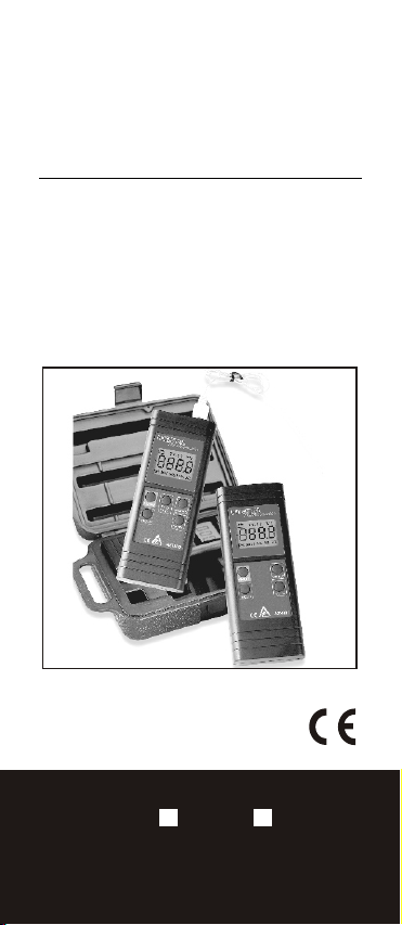
K TYPE THERMOMETER
Model: 8801 8803
Page 2
INTRODUCTION
The 8801 and 8803 are 3 1/2 digit, hand
-held thermometer designed to use Ktype thermocouple as temperature
sensor.
8801 For 1 K-type Thermocouple input
8803 For 2 K-type Thermocouple input
SAFETY
To avoid electrical shock, disconnect
the thermocouple connectors from the
thermometer before removing the
battery cover and do not use this
meter on voltage at the measurement
surface beyond 24V AC or 60V DC.
To avoid damage or burns, do not
apply this meter in microwave ovens.
To ensure lead quality, avoid repeating
sharp bends in the leads as it can
damage the thermocouple leads,
especially near the connector.
T1-T2
oo
C F
-
+
O
N
H
O
L
D
C
/
F
REC MAX HOLD MIN REL
N
O
D
OL
H
1
Page 3
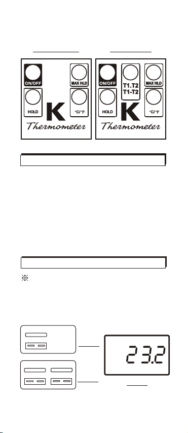
Model: 8801
Single Input
Model: 8803
Dual Input
BUTTON DESCRIPTION
ON/OFF
oo
C/ F
HOLD
MAX HLD
T1.T2
T1-T2
Power ON and Power OFF
Unit selectable C or F
oo
Freeze the current reading
Record Maximum reading
T1 temperature or
T2 temperature or differential
temperature between T1&
T2
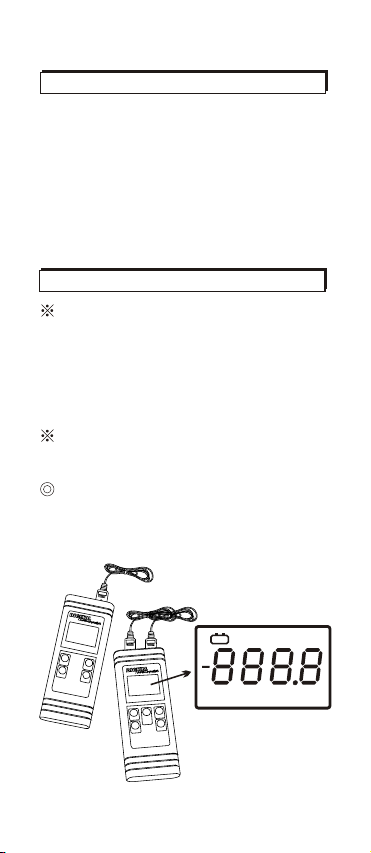
OPERATION
Plug thermocouple in the meter as
shown Figure 1 or 2.
Press ON/OFF button to start. Fig. 3
shows the normal display when either
T1 or T2 thermocouple is pluged in.
++
#8801
Fig.1
o
C
T1T1
T2T2
#8803
++
++
Fig.2
Fig.3
2
Page 4

SELECTING C / F
oo
Press C/ F button to select C or F.
The display will show " C" or " F" to
oo
oo
oo
indicate which scale has been selected.
See Fig.3 and Fig.5 ,an example to
toggle unit from C to F.
oo
NO-SLEEP MODE DISABLEMENT
Press ON/OFF button to turn off the
meter. The meter will auto shut off if
no button is pressed within 20 minutes.
To disable auto power off, press HOLD
and ON/OFF key simultaneously, until an
"n" appears on the screen (See Fig.4 ),
then release ON/OFF button and HOLD
button, the meter turns to the normal
reading (Fig.5).
Operate the same procedure before
using the meter, otherwise, the meter is
default to the auto power off about 20
minutes.
o
F
Fig.4
Fig.5
TEMPERATURE MEAS.
The meter displays the temperature of
the thermocouple connected to the
selected input.
3
Page 5

Press T1.T2/T1-T2 button to display the
temperature for T1 input. (Fig.8) Press
T1.T2/T1-T2 button again to display the
temperature for T2 input. (Fig.7)
Press T1.T2/T1-T2 button one more time
to display the differential temperature
between the two thermocouples.(Fig.9)
The display will show T1,T2 or T1-T2 in
turns by pressing the same button.
Note:
Model 8801 can only display one
temperature. Only make sure the
thermocouple is plugged at the left side
on the top . No reading but 4 dashes (---
-) (Fig.6) will be appeared until you plug
in a K type thermocouple.
o
C
T1
o
C
T2
Fig.6
T1
o
C
Fig.7
T1-T2
o
C
Fig.8 Fig.9
MAX HOLD FUNCTION
Select the desired input, then press the
MAX HLD button.
The meter will record and update the
maximum values. "MAX" "HOLD"
appears on the display.(Fig.10)
4
Page 6

To release the MAX HOLD function,
press the MAX HLD button again.
When the MAX function is set, the meter
is recording and will update the
maximum measurement display with a
new maximum reading .
o
F
Fig.10
MAX HOLD
HOLD FUNCTION
Press the HOLD button to apply data
HOLD Function. The "HOLD" appears
on the display then(Fig.11). When HOLD
function is set, the meter holds the
present readings and stops all further
measurement. To release HOLD function
,press the HOLD button again.
The meter will
resume taking
o
F
measurements.
Fig.11
HOLD
TROUBLE SHOOTING
"- - - - " appear.
?
Check the measurement thermocouple
is plugged in the right input. If the
screen shows T1,but no thermocouple
are plugged in T1 or thermocouple is
wrong plugged in T2, four dashes(----)
will appear. Put the thermocouple in
the correct input .
-
+
indication.
?
Replace with a new battery.
5
Page 7

MATERIAL SUPPLIED
This package contains:
1. The meter x 1
2. Type K thermocouple probe x 1
3. Battery 9.0volt x 1
4. Instruction manual x 1
SPECIFICATION
oo
RANGE
ACCURACY
DISPLAY
SAMPLING
RATES
DIMENSION
-50 C to 1300 C
o
(-58 F to 2000 F)
oo
-50 to 1000 0.3% rdg + 1
1000 to 1300 0.5% rdg + 1
oo o
-58 F to 1800 F 0.3% rdg + 2 F
(18 to 28 C Ambient Temperature)
o
CC C
o
CC C
++
--
oo
++
--
++
--
o
37mm X 42mm LCD, max.
2.5 per second
181mm X 71mm X 30mm
o
Temperature Coefficient:
0.1 times the applicable accuracy
specification per C from 0 C to 18 C
oo
and 28 C to 50 C
ooo
REPLACING THE BATTERY
Replace your 9-volt battery when:
-
+
The icon appears on the left top
of the screen (See Fig.12).
The display is dimed or the meter will
not power on.
Even if the battery was recently replaced,
check its voltage level if you get no
response from your instrument.
6
Page 8

To replace the battery:
1. Lay the instrument face-down on a
clean, flat surface.(See Fig.13)
2. Remove the battery by screw driver
follow the arrow sign and observe
indicated polarity and close the cover
after replacing with a new battery.
o
-
+
F
Fig.12
++
Fig.13
Remove battery from instruments that
you do not plan to use for a month or
more. Do not leave battery in instrument.
WARRANTY
The meter is warranted to be free from
defects in material and workmanship for
a period of one years from the date of
purchase.
This warranty covers normal operation
and does not cover batteries, misuse,
abuse, alteration, tampering, neglect,
improper maintenance, or damage
resulting from leaking batteries. Proof of
purchase is required for warranty repairs.
7
Page 9

RETURN AUTHORIZATION
Authorization must be obtained from the
supplier before returning items for any
reason.
When requiring a RA (Return
Authorization) , please include data
regarding the defective reason, the
meters are to be returned along with
good packing to prevent any damage in
shipment and insured against possible
damage or loss .
CE CERTIFICATION
The meter conforms to the following
standards:
* EN 50081-1/1992 : EN 55022
* EN 50082-1/1997 : EN 55024
(EN 61000-4-2/-3/-8, ENV 50204)
, the meter complies with the essential
protection requirements of Council
Directive 89/336/EEC on the approximation of the laws of the Member
States relating to electromagnetic
compatibility.
8
 Loading...