

Page 1

DIGITAL
LIGHT METER
Page 2

TABLE OF CONTENTS
.
.
.
.
.
.
A
.
1. FEATURES................................................................... 1
2. SPECIFICATIONS......................................................... 1
2-1 General Specifications............................................
2-2 Electrical Specifications..........................................
1
3
3. FRONT PANEL DESCRIPTION.......................................
3-1 Display................................................................. 4
3-2 Power Off/On Button.............................................4
3-3 Data Hold Button.................................................. 4
3-4 LUX/FC(Ft-cd) Button............................................ 4
3-5 LCD Contrast Adjust.............................................. 4
3-6 Memory "Record" Button....................................... 4
3-7 Memory "CALL" Button..........................................4
3-8 Light Source Select Button.....................................4
3-9 Zero Button.......................................................... 4
3-10 % Button(Relativity).............................................4
3-11 Range Switch.......................................................4
3-12 Light Sensor........................................................
3-13 Sensor Cover.......................................................
3-14 Light Sensor Plug................................................. 4
3-15 Light Sensor Input Socket.....................................4
3-16 RS-232 Output..................................................... 4
3-17 Battery Compartment/Cover.................................
4
4
4
4
4. MEASURING PROCEDURE.............................................5
DDITIONAL FEATURES...............................................8
5.
6. RS232 PC SERIAL INTERFACE...................................... 8
7. BATTERY REPLACEMENT.............................................
10
Page 3
1. FEATURES
2. SPEC
S
* Microprocessor circuit ensure high accuracy, and also
and also provides special functions and features.
* Super large LCD display with contrast adjustment for
best viewing angle.
* Dual function display.
* Heavy duty & compact case.
* Records Maximum, Minimum and Average readings.
* Data hold.
* Auto power off saves battery life.
* Operates from 9V battery.
* RS 232 PC serial interface.
* Spectrum of photo sensor meets C.I.E..
* Wide range measurement both for LUX & Foot Candle
units.
* Relative % light measurement.
* User selectable lighting type (Tungsten, Fluorescent,
Daylight or Mercury).
* Zero adjustment by push button.
IFICATION
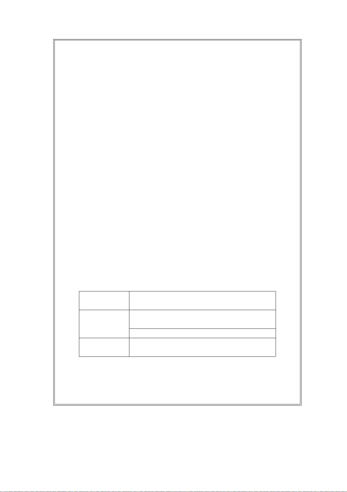
2-1 General Specifications
Circuit Custom one-chip microprocessor LSI
circuit.
Display 13 mm(0.5") Super large LCD display with
contrast adjustment for best viewing angle.
Dual function display.
Lighting Type Daylight, Tungsten,
Selection Fluorescent, Mercury lamp.
1
Page 4
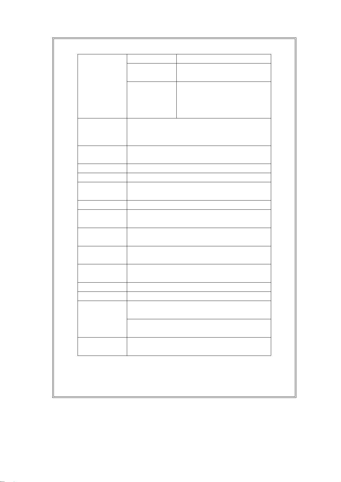
Measurement LUX 0 - 50,000 LUX, 3 ranges.
& ranges Foot-candle 0 -5,000 Ft-cd, 3 ranges.
Relativity 0 to 1999 %.
(Relative to the range
selected and the measured
value)
Sensor The exclusive photo diode & color
correction filter, spectrum designed to meet
C. I. E.
Memory Records Maximum, Minimum and Average
Recall readings with RECALL facilities.
Sample Time Approx. 0.4 sec.
Zero Adj. By push button.
Power off Manual off by push button, or Auto shut off
after 10 minutes.
Data Output RS 232 PC serial interface.
Over Load "- - - -"
Indication
Operating 0 蚓 to 50 蚓(32 蚌 to 122 蚌).
Temperature
Operating Max. 80% RH.
Humidity
Power Supply 006P DC 9V battery(heavy duty)
or equivalent.
Power Current Approx. DC 5.3 mA.
Weight 335 g/0.77 LB (included batteries)
Size Main instrument:
180 x 72 x 32 mm(7.1 x 2.8 x1.3 inch).
Sensor probe:
85x55x12 mm(3.2x2.2x0.5 inch).
Accessories Instruction manual.
Sensor with protective cover.
2
Page 5

2-2 Electrical Specifications (23 5 蚓)
Measurement Range Max. In-range
Display
2,000 Lux 0 - 1,999 Lux
LUX 20,000 Lux 1,800 - 19,990 Lux
50,000 Lux 18,000 - 50,000 Lux
200 Ft-cd 0 - 186.0 Ft-cd
Foot-candle 2,000 Ft-cd 167 - 1,860 Ft-cd
5,000 Ft-cd 1,670 - 5,000 Ft-cd
Range Resolution Accuracy
2,000 LUX 1 Lux
20,000 LUX 10 Lux
50,000 LUX 100 Lux 4 % + 2 dgt)
200 Ft-cd 0.1 Ft-cd
2,000 Ft-cd 1 Ft-cd
5,000 Ft-cd 10 Ft-cd
Note : Accuracy tested by a standard parallel light
tungsten lamp of 2856 袁 temperature.
Measurement Range Resolution
Relativity 0 to 1999 % 1 %
3
Page 6

3. FRONT PANEL DESCRIPTION
4
Fig. 1
3-1 Display 3-8 Light Source
3-2 Power Off/On Select Button
Button 3-9 Zero Button
3-3 Data Hold Button 3-10 % Button (Relativity)
3-4 LUX/FC(Ft-cd) 3-11 Range Switch
Button 3-12 Light Sensor
3-5 LCD Contrast 3-13 Sensor Cover
Adjust 3-14 Light Sensor Plug
3-6 Memory "Record" 3-15 Light Sensor Input Socket
Button 3-16 RS-232 Output
3-7 Memory "Call" 3-17 Battery Compartment/
Button Cover
Page 7

4. MEASURING PROCEDURE
(1) Push the "Power Off/On Button"(3-2, Fig. 1) to
switch the instrument on.
(2) Zero Adjust Procedures
* Cover the Light Sensor(3-12, Fig, 1) using the Sensor
Cover provided (3-13, Fig. 1).
* Slide the "Range Switch"(3-11, Fig. 1) to the 2000
LUX position.
* Push the "Zero Button"(3-9, Fig. 1), then display will
show zero values.
* Upon completion, remove the sensor cover.
(2) Select the desired measuring unit by pressing the
"LUX/FC Button"(3-4, Fig. 1). The display will indicate
the selected unit of "LUX" or "Ft-cd".
(3) Determine the lighting type (Daylight, Tungsten,
Fluorescent or Mercury lamp) by pressing the
"Light Source Select Button"(3-8, Fig. 1)
* The LCD will indicate the selected lighting type using
the following symbols :
L = Tungsten, F = Fluorescent
S = Day Light, C = Mercury
(4) Select the max. range using the "Range Switch"(3-11,
Fig. 1).
* If the display shows "- - - - ", it indicates an
overload condition, select the next higher range.
* If the display shows "_ _ _ _ ", it indicates an
out-of-range, select the next lower range.
(5) Position the Light Sensor(3-12, Fig. 1) directly
under the light source.
5
Page 8

(6) * On the 20000 LUX range, the last digit will be
shown on the lower line of LCD display.
* On the 50000 LUX range, the last two digits will
show on the lower line of LCD display.
* For example :
On the 20000 range, if the display sho1562 LUX
0
that means the real display is 15620 LUX.
* Please note the digits on the lower display are
multipliers only (i.e. x10 & x 100 respectively).
These digits will not change, and will only inducate 0.
(7) Data Hold :
* During measurement, pushing the "Data Hold
Button"(3-3, Fig. 1) will hold the display values &
the LCD will show the "D.H" symbol.
* To cancel the Data Hold function, Press the Data
Hold Button, once more.
(8) Relative % light measurement :
* During measurement, press the "% Button"(3-10,
Fig. 1). The current measured value will be indicated
as " 100 % ".
* All the subsequent measurements will be indicated
as a percentage, relative to the value when the
button was pressed.
The formula used is as shown below :
The new light values
x 100
The light values when the
" % " button was pressed
* To de-activated this feature, Press the "% Button"
(3-10, Fig. 1) again
6
Page 9

(9) Data Record( Max., Min., Average reading)
T
* The DATA RECORD function displays the
maximum, minimum and average readings. To start
the DATA RECORD function, press the "Record
Button"(3-6, Fig. 1) once. "REC" marker will appear
on the LCD display.
With the "REC" symbol indicated on the display
*
(a) Push the "CALL Button"(3-7, Fig. 1) once,
then the "Max" symbol with the maximum values
recorded will appear on the LCD display.
(b) Push the "CALL Button" once again, the "Min"
symbol with the minimum values recorded will
appear on the LCD display.
(c) Push the "CALL Button" once more, the "AVG"
symbol with the average values will appear on
the LCD display.
(d) To de-activate the Data Record function, Press
the "Record Button" (3-6, Fig. 1) once again.
All associated anunciators will disappear from the
display.
(10) For quick measurement, follow the procedures
shown below :
Main procedures :
DETERMINE SELEC
POWER ZERO * LUX or Ft-cd RANGE
ON * LIGHTING TYPE
7
Page 10

Optional measuring procedures :
T
DATA HOLD MEMORY RECORD RS232 OUTPU
Max., Min. AVG
Power management
AUTO POWER OFF or MANUAL POWER OFF
(Not activated under memory record function
during Memory
Record Selection)
5. ADDITIONAL FEATURES
(a) The instrument has built-in "Auto Power Shut-off"
in order to prolong battery life. The meter will switch
off automatically if none of the buttons are pressed
within 10 min.
To de-activate this feature, Select the memory record
function during measurement, by pressing the
"RECORD" button(3-6, fig.1).
(b) The instrument also features the ability to adjust the
contrast of the display.
This is achieved by controlling the "LCD Contrast
Adjust" pot (3-5, fig. 1).
6. RS232 PC INTERFACE
The instrument features an RS232 output via 3.5 mm
Terminal ( 3-13, Fig. 1).
The connector output is a 16 digit data stream which
can be utilized to the user's specific application.
8
Page 11

An RS232 lead with the following connection will be
required to link the instrument with the PC serial input.
Meter PC
(3.5 mm jack plug) (9W 'D" Connector)
Center Pin......................................Pin 2
Ground/shield....................................Pin 5
The 16 digit data stream will be displayed in the
following format :
D15 D14 D13 D12 D11 D10 D9 D8 D7 D6 D5 D4 D3 D2 D1 D0
Each digit indicate the following status :
D0 End Word
D1 to D4 Upper Display reading, D1=LSD, D4=MSD
D5 to D8 Lower Display reading, D5=LSD, D8=MSD
D9 Decimal Point(DP) for Upper display.
0 = No DP, 1= 1 DP, 2 = 2 DP, 3 = 3 DP
D10 Decimal Point (DP) for lower display
0 = No DP, 1= 1 DP, 2 = 2 DP, 3 = 3 DP
D11 & D12 Anunuciator for Upper Display
00 =No Symbol 07 = mg/L 14 =mS
01 =C 08 = m/s 15 =Lux
02 =F 09 = Knots 16 =Ft-cd
03 = % 10 = Km/h 17 =dB
04 = % RH 11 = Ft/min 18 =mV
05 = % PH 12 = mile/h
06 = % O 2 13 = uS
D13 Anunuciator for Lower Display
0 =No Symbol 1 =C 2 =F
D14 Reading Polarity for the Display
0 = Both upper & lower display value are "+".
1 = Upper "-", Lower "+".
2 = Upper "+", Lower "-".
3 = Both upper & lower display value are "-".
D15 Start Word
9
Page 12

7. BATTERY REPLACEMENT
(1) When the left corner of LCD display show "LBT",
it is necessary to replace the battery. However,
in-spec measurement may still be made for several
hours after low battery indicator appears before the
instrument become inaccurate.
(2) Slide the Battery Cover(3-17, Fig. 1) away from the
instrument and remove the battery.
(3) Install a 9V battery(PP3 type) and replace the cover.
10
9912-LX-105-NDN
 Loading...