

Page 1

CONDUCTIVITY/
TDS METER
+ PH meter
Model : DCT2001
Page 2

TABLE OF CONTENTS
.
.
.
.
.
.
.
.
1. FEATURES............................................................... 1
2. SPECIFICATIONS.....................................................2
2-1 General Specifications........................................
2-2. Conductivity/TDS/Temp. specifications...............
a. Conductivity..................................................... 3
b. TDS ( Total Dissolved Dolids )........................... 4
c. Temperature.................................................... 4
2-3 PH meter specifications......................................
2
3
4
3. FRONT PANEL DESCRIPTION...................................
4. MEASURING PROCEDURE.........................................7
4-1 Conductivity measurement................................
4-2 TDS measurement............................................
4-3 Calibration procedures of Conductivity meter......
4-4 PH meter..........................................................11
a. PH Measurement.............................................. 11
b. mV Measurement............................................. 12
c. Temp. Measurement......................................... 12
d. Manual temperature compensation.................... 12
e. Automatic temperature compensation................ 13
f. Two Points Calibration....................................... 14
4-5 Other functions ( Hold, Memory ) ......................15
5. AUTO POWER OFF DISABLE.....................................16
6. RS232 PC SERIAL INTERFACE..................................
7. BATTERY REPLACEMENT..........................................18
8. OPTIONAL PROBES & ACCESSORIES.........................18
5
7
8
9
16
Page 3

1. FEATURES
* Conductivity/TDS ( Total Dissolved Solids ) Meter
+ PH Meter, multi functions & intelligent features.
* Conductivity includs 2 ranges : 2 mS, 20 mS.
TDS has 2 ranges : 2,000 PPM, 20,000 PPM.
Temperature measurement range from 0 - 60 蚓 /
32 - 140蚌.
* Conductivity/TDS meter build in automatic temperature
compensation circuit, adjustable between 0 to 5.0%
per 蚓.
* Conductivity/TDS meter uses carbon rod electrode with
long life using separated pobe is convenient for remote
measurement.
* PH meter has mV ( millivolt ) function for
mV measurement ( Be plugged with optional ORP probe
ORP-04 to be a professional ORP meter)
* PH meter with wide manual temperature compensation
adjustment and optional ATC (Automatic Temp.
Compensation) probe is available.
* Microprocessor circuit, intelligent function.
* Records maximum and minimum readings with recall.
* Data hold.
* Auto shut off saves battery life.
* RS 232 PC serial interface.
* Temperature function with 蚓 & 蚌 display unit.
1
Page 4
2. SPECIFICATIONS
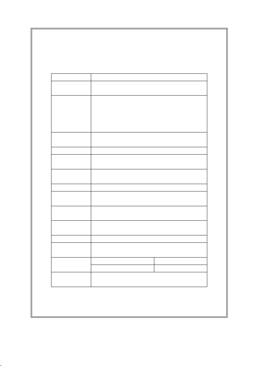
2-1 General specifications
Circuit Microprocessor LSI circuit.
Display 51 mm x 32 mm, dual function LCD display,
15 mm ( 0.6" ) digit size.
Measurement * Conductivity
* TDS ( Total Dissolved Solids )
* Temperature ( use the CD/TDS probe )
* PH
* mV
Memory Records maximum and minimum
Recall readings with recall.
Data hold Hold the current reading value on the display.
Memory Maximum and minimum reading values can
Recall be saved and retrieved by record function.
Power off Auto shut off saves battery life, or manual
off by push button.
Data Output RS 232 computer serial interface.
Overload "- - - -" symbol on the display.
indication
Operating 0 to 50 蚓 - main instrument.
Temperature 0 to 60 蚓 - Conductivity/CT probe only.
Operating Max. 80% RH.
Humidity
Sampling Time Approx. 0.8 second.
Power Supply 006P DC 9V battery
( Alkaline or Heavy duty type ).
Power Current Meter only Approx. DC 4.2 mA.
Meter + CD/TDS probe Approx. DC 6.0 mA.
Weight 250 g/0.55 LB ( battery included ).
* Main meter only, not including probe.
2
Page 5
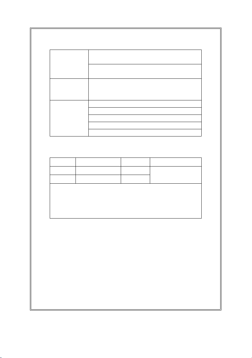
Size
Main meter :
195 x 68 x 30 mm ( 7.6 x 2.6 x 1.2 inch ).
Conductivity/TDS probe :
Round, 22 mm Dia. x 120 mm length.
Accessories Conductivity/TDS probe...............1 PC.
included Operation manual....................... 1 PC.
Carrying case, CA-06...................1 PC.
Optional PH electrode.............PE-03, PE-11, PE-01
Accessories ATC probe for PH meter.......... YK-200PATC
ORP electrode.........................ORP-04
RS232 cable, UPCB-02............ UPCB-02
Application Software............SW-U801-WIN
2-2. Conductivity/TDS/Temp. specifications
A. Conductivity
Range Measurement Resolution Accuracy
2 mS 0.2 to 2.000 mS 0.001 mS ( 3 % F.S. + 1 d )
20 mS 2 to 20.00 mS 0.01 mS
* F.S. - Full scale
* Temperature Compensation :
Automatic from 0 to 60 蚓 ( 32 - 140 蚌 ), with temperature
compensation factor variable between 0 to 5.0% per C.
* mS - milli Simens
* @ 23 5蚓
3
Page 6
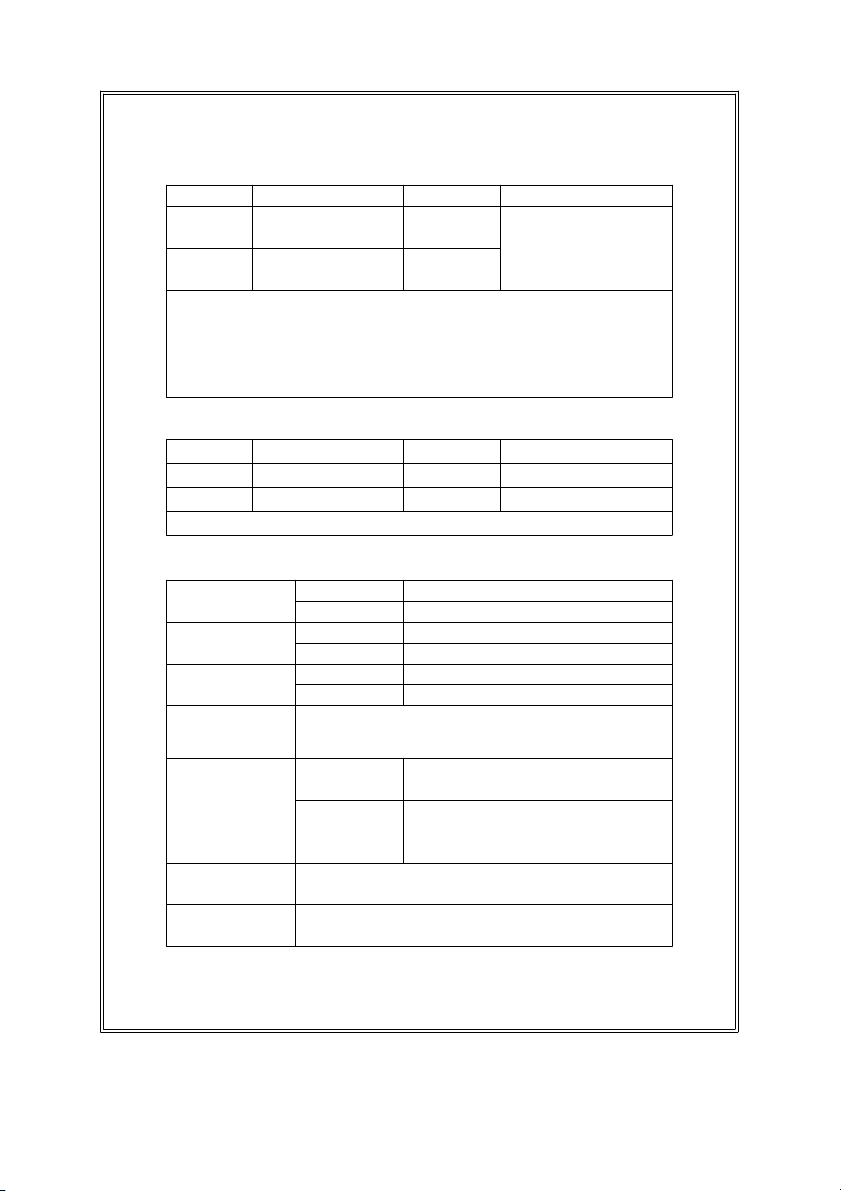
B. TDS ( Total Dissolved Dolids )
e
e
蚓
(
蚌
)
e
n
s
T
蚓
Rang
2,000 132 to 1,320 1 PPM
PPM PPM ( 3 % F.S. + 1 d )
20,000 1,320 to 13,200 10 PPM
PPM PPM
Measurement ResolutionAccuracy
* F.S. - Full scal
* Temperature Compensation :
Automatic from 0 to 60
32 - 140
, with temperatur
compensation factor variable between 0 to 5.0% per C.
* PPM - parts per millio
* @ 23 5蚓
C. Temperature
Function Measuring Range Resolution Accuracy
蚓 0 蚓 to 60 蚓 0.1 蚓 0.8 蚓
蚌 32 蚌 to 140 蚌 0.1 蚌 1.5 蚌
* @ 23 5蚓
2-3 PH meter specification
Measurement PH 0 to 14 PH
mV -1999 mV to 1999 mV
Resolution PH 0.01 PH
mV 1 mV
Accuracy PH 0.02 PH + 2 d)
* Meter only
Input 10 -12 ohm
Impedance
emperature Manual 0 to 100 蚓, be adjusted by
Compensation push button on front panel.
for pH Automatic With the optional TEMP.
measurement ( ATC ) probe ( YK-200PATC )
pH PH7, PH4, and PH10, 3 points calibration
Calibration ensure the best linearity and accuracy.
PH Optional,
Electrode Any PH electrode with BNC connector.
mV 0.5% + 2 d)
0 to 65
.
4
Page 7

3. FRONT PANEL DESCRIPTION
Fig. 1
5
Page 8

3-1 Display
A
蚓,蚌
R
R
3-2 Power Button
3-3 REC. Button
3-4 Hold Button
3-5
3-6 B Button ( Range Button )
3-7 C Button ( CD/TDS Button )
3-8 D Button ( TEMP. C Button )
3-9 Battery Compartment/Cover
3-10 PH BNC Input Socket
3-11 Lock Switch
3-12 Conductivity/TDS Input Socket
3-13 RS-232 Out Terminal
3-14 Stand
3-15 PH 7 V
3-16 PH 4/PH 10 V
3-17 Conductivity/TDS Probe
3-18 Conductivity/TDS Probe pLug
Button (
up Button
PH/mV Button/left Button
CAL Button/down Button
Button )
6
Fig. 1
Page 9

4. MEASURING PROCEDURE
4-1 Conductivity measurement
1) Plug the " Conductivity/TDS Probe plug " ( 3-18, Fig.1)
into the " Conductivity/TDS Socket " ( 3-12, Fig. 1 )
Make sure that the probe lock switch ( 3-11, Fig. 1 )
should slide to the lock position ( ).
2) Power on the instrument by pushing the " Power Button "
( 3-2, Fig.1 )
3) Push the " CD/TDS " Button ( C Button ) ( 3-7, Fig. 1 ), and
select the function to the conductivity measurement. The
display will show the unit of " mS ".
4) The instrument will default to 2% per 蚓 Temperature
Compensation factor. The meter has built-in Automatic
Temperature Compensation adjustable between 0 to 5.0 %
per 蚓.
In order to change the default value carry out the
following procedures :
a. Push the " Temp. C Button ( D Button ) " ( 3-8, Fig. 1 ),
the display will show :
o
mS 1 蚓
7
Page 10

b.
)
)
Use the
" up Button ( A Button ) " ( 3-5, Fig. 1 ),
" left Button ( B Button ) " ( 3-6, Fig. 1 )
" down Button ( C Button ) " ( 3-7, Fig. 1 )
to select the desired value of Temperature
Compensation factor.
c. Once the desired value is reached, push the " Temp.
C Button ( D Button ) " ( 3-8, Fig. 1 ) to set the new
value.
5) Select the applicable range, by using the " Range Button
( B Button ) " ( 3-6, Fig. 1 ).
* If the display shows "- - - -", it indicates an overload
condition, select the next higher range.
* If the display shows "_ _ _ _", it indicates an
out-of-range condition, select the next lower range.
6) Immerse the head of " Conductivity/TDS Probe " ( 3-17, Fig. 1
into the solution, up to the immersion level.
7
During the measurement, the lower LCD Display will
show the temperature of the solution.
* Push the " 蚓/蚌 Button " ( 3-5, Fig. 1 ) to change
the temperature display unit from " 蚓 to 蚌 "
or " 蚌 to 蚓 ".
4-2 TDS measurement
The operation procedures are same as the above 4-1,
except that push the " CD/TDS " Button ( C Button ) ( 3 -7,
Fig. 1 ), and select the function to the TDS measurement. The
lower display will show the text of " P ".
8
Page 11

4-3 Calibration procedures of Conductivity meter
The meter has been calibrated during manufacture.
However, it may be necessary to re-calibrate periodically.
Particularly when the instrument is used for a long period or
when the conductivity electrode is changed.
To re-calibrate the instrument, follow the procedures
shown below :
Range 1 ( 2 mS range ) calibration
1) Prepare a " 1.413 mS Calibration Solution ".
2) Immerse the head of " Conductivity Probe " ( 3-17, Fig. 1 )
into the 1,413 mS solution up to the immersion level.
3) Select the range to the " 2 mS " position.
4) Set the temperature coefficient factor value to " 2.0% per
蚓 "
5) At the same time push the following buttons together :
a. REC.( MAX./MIN. ) Button ( 3-3, Fig. 1 )
b. HOLD Button ( 3-4, Fig. 1 )
The upper display will show the flashing text of " CAL ".
The low display will show the flashing text of " 1.413 ".
6) Please release the two buttons when the display shows as
above and start flashing and then when the text stop
flashing, the range 1 will be calibrated to 1.413 mS
( There maybe a little deviation, and it is normal ).
*
After released two buttons but before the text (CAL,
1.413 ) stop flashing, if push the " HOLD Button " will
cancel the calibration procedures, the meter will return
to previous calibration value.
9
Page 12
Range 2 ( 20 mS range ) calibration
1) Prepare a " 12.88 mS Calibration Solution ".
2) Immerse the head of " Conductivity Probe " ( 3-17, Fig. 1 )
into the 12.88 mS solution up to the immersion level.
3) Select the range to the " 20 mS " position.
4) Set the temperature coefficient factor value to " 2.0% per
蚓 "
5) At the same time push the following buttons together :
a. REC.( MAX./MIN. ) Button ( 3-3, Fig. 1 )
b. HOLD Button ( 3-4, Fig. 1 )
The upper display will show the flashing text of " CAL ".
The low display will show the flashing text of " 12.88 "
6) Please release the two buttons when the display shows as
above and start flashing and then when the text stop
flashing, the range 2 will be calibrated to 12.88 mS
( There maybe a little deviation, and it is normal ).
*
After released two buttons but before the text
(CAL, 12.88 ) stop flashing, if push the " HOLD Button
" will cancel the calibration procedures, the meter will
return to previous calibration value.
10
Page 13

4-4 PH meter
* Make sure that the probe lock switch ( 3-11, Fig. 1 )
had switched to the lock position ( ).
* Make sure that the " Conductivity/TDS Plug "
( 3-18, Fig. 1 ) had taken away from the meter.
a. PH Measurement
Whenever the calibration procedures are recommended to
be done before PH measurement.
1) Connect the PH ELECTRODE to the " PH BNC Input
Socket " ( 3-10, Fig. 1 ).
2) Power on the instrument by pressing the " Power
Button " ( 3-2, Fig. 1 ).
3) Press the " PH/mV Button " ( 3-6, Fig. 1 ) to select
the PH function with a "PH" symbol on the display.
4) * If the operating is under the " Manual temperature
compensation ", then please refer to the " 4-4, d "
calibration procedures.
* If the operating is under the " Automatic temperature
compensation ", then please refer to the " 4-4, e "
calibration procedures.
5) Place the electrode into the solution, and then the instrument
will have the PH value on the display.
6) After the measurement, please rinse the electrode with
distilled water.
11
Page 14

b. mV Measurement
The instrument built in mV ( millivolt ) measurement
function, which enable you to make ion-selective, ORP
(oxidation-reduction potential), and other precise mV
measurements.
Press the " PH/mV Button " ( 3-6, Fig. 1 ) to select
the mV function with a " mV " symbol on the display.
c. Temp. Measurement
1) Plug the " Optional ATC Temp. Probe, YK-200PATC "
into the " Probe Input Socket " ( 3-12, Fig. 1 ).
2) * If you intend to measure " 蚓 ", then press the " 蚓/ 蚌
Button " ( 3-5, Fig. 1 ) and select the " 蚓 " unit.
* If you intend to measure " 蚌 ", then press the " 蚓/ 蚌
Button " ( 3-5, Fig. 1 ) and select the " 蚌 " unit.
3) Place the " Temp. Probe " into the solution, and the instrument
will have the temperature value on the display.
d. Manual temperature compensation
Before the manual temperature compensation adjust
procedures, make sure there are no ATC probe or other
probe in the " Probe Input Socket" ( 3-12, Fig. 1 ).
1) Power on the instrument by pressing the " Power
Button " ( 3-2, Fig. 1 ).
12
Page 15

2) Press the " PH/mV Button " ( 3-6, Fig. 1 ) to select
the PH function with a " PH " symbol on the display
* Press the " TEMP. C Button " ( 3-8, Fig. 1 ) first,
The upper display will show the measured PH values.
the lower display will show the manual temperature
compensation value.
* Use the " Left Button " ( 3-6, Fig. 1 ), " Up Button "
( 3-5, Fig. 1 ) and the " Down Button " ( 3-7, Fig. 1 ) to
adjust the manual temperature compensation value.
e. Automatic temperature compensation
1) Plug the " Optional ATC Temp. Probe, YK-200PACT "
into the " Probe Input Socket " ( 3-12, Fig. 1 ).
Make sure that the probe lock switch ( 3-11, Fig. 1 )
should slide to the lock position ( ).
2) Power on the meter.
3) Press the " PH/mV Button " ( 3-6, Fig. 1 ) to select
the PH function with a "PH" symbol on the display
4) Place the "Temp. Probe" into the solution, then
temperature will be compensated automatically for PH
measurement.
13
Page 16

f. Two Points Calibration
PH 7 calibration
Connect the PH ELECTRODE with the " BNC socket "
( 3-10, Fig. 1 ) and immerse the electrode in the PH7
buffer solution ( optional ).
Press the " CAL Button " ( 3-7, Fig. 1 ) then the upper
display shows texts of " CAL " and the lower display
shows the default calibration value.
* The texts " CAL " will flash for around 5 seconds.
After that, the meter calibrates itself automatically.
The upper display will show the calibrated value,
the lower display will show the temperature value.
PH 4 or PH 10 calibration
1) Rinse the electrode with distilled water.
2) Immerse the electrode in the PH4 buffer solution ( or PH10
buffer solution ).
3) Press the " CAL Button " ( 3-7, Fig. 1 ) then the upper
display shows texts of " CAL " and the lower display
shows the default calibration value.
* The texts " CAL " will flash for around 5 seconds.
After that, the meter calibrate itself automatically.
The upper display will show the calibrated value,
the lower display will show the temperature value.
4) Rinse the electrode with distilled water again and then
5) Repeat above (2) to (4) procedures two times at least.
6) The instrument and electrode are now finished the
" TWO POINTS CALIBRATION " & ready for the
measurement.
14
Page 17

4-5 Other functions ( Hold, Memory )
Data Hold
Press the " Hold Button " ( 3-4, Fig. 1 ) will hold the
measured value & the LCD will indicate a " HOLD " symbol
on the display during the measuring.
* Press the " Hold Button " again to exit the data hold
function.
Data Record ( Max., Min. reading )
* The data record function records the maximum and
minimum readings. Press the " REC. Button " ( 3-3, Fig. 1 )
to start the Data Record function and there will be a
" REC " symbol on the display.
* With the " REC " symbol on the display :
a) Press the " REC. Button " ( 3-3, Fig. 1 ) once, the
" REC Max " symbol along with the maximum value
will appear on the display.
If intend to delete the maximum value, just press
the " Hold Button " ( 3-4, Fig. 1 ) for a while, and then
the display will show the " REC " symbol only &
execute the memory function continuously.
b) Press the " REC. Button " ( 3-3, Fig. 1 ) again, the
" REC Min " symbol along with the minimum value
will appear on the display.
If intend to delete the minimum value, just press
the " Hold Button " ( 3-4, Fig. 1 ) for a while, and then
the display will show the " REC " symbol only &
execute the memory function continuously.
c) To exit the memory record function, just press the
" REC " button for 2 seconds at least. The display will
revert to the current reading.
15
Page 18

5. AUTO POWER OFF DISABLE
The instrument has " Auto Power Off " function in
order to prolong battery life. The meter will shut
off automatically if none of the buttons are pressed
in approx. 10 min.
To disable this function, Select the memory record
function during the measurement by pressing the
" REC. Button " ( 3-3, Fig. 1 ).
6. RS232 PC SERIAL INTERFACE
The instrument features RS232 output via
3.5 mm Terminal ( 3-13, Fig. 1 ).
The signal output is a 16 digits data stream which
can be utilized for user's specific application.
A RS232 lead with the following connection will
be required to link the instrument with the PC
serial interface.
Meter PC
(3.5 mm jack plug) (9W 'D" Connector)
Center Pin................................ Pin 4 Pin 2
2.2 K
Ground/shield..............................Pin 2 Pin 5 resistor
16
Page 19

The 16 digits data stream will be displayed in the
4
蚓
蚌
following format :
D15 D14 D13 D12 D11 D10 D9 D8 D7 D6 D5 D4 D3 D2 D1 D0
Each digit indicates the following status :
D0 End Word
D1 & D8 Display reading, D1 = LSD, D8 = MSD
For example :
If the display reading is 1234, then D8 to D1 is :
0000123
D9 Decimal Point(DP), position from right to the left
0 = No DP, 1= 1 DP, 2 = 2 DP, 3 = 3 DP
D10 Polarity
0 = Positive 1 = Negative
D11 & D12 Annunciator for Display
= 01
mV = 18 mS = 14 PPM = 19
OF2= 06 mg/L = 07
D13 When send the upper display data = 1
When send the lower display data = 2
D14 4
D15 Start Word
= 02 PH = 05
RS232 FORMAT : 9600, N, 8, 1
17
Page 20

7. BATTERY REPLACEMENT
e
蚓0 蚓
蚓
蚌32
蚌
蚌
*
e
1) When the left corner of LCD display show " ", it
is necessary to replace the battery. However, in-spec.
measurement may still be made for several hours after
low battery indicator appears.
2) Slide the " Battery Cover " (3-14, Fig. 1) away from the
instrument and remove the battery.
3) Replace with 9V battery ( Alkaline or Heavy duty type )
and reinstate the cover.
4) Make sure the battery cover is secured after changing the
battery.
8. OPTIONAL PROBES & ACCESSORIES
ORP ELECTRODE ORP electrode ORP-04 plug into the
meter ( select to the mV
Model : function ) to become a professional
ORP-04 ORP (oxidation-reduction potential)
Meter.
ATC
PROBE
Model :
YK-200PATC
MeasurementRang
to 65
to 149
Automatic Temperatur
Compensation Probe for PH
function.
18
Page 21

PH ELECTRODE General purpose, laboratory
&
&
&
T
Model : field usage. 12 mm dia. x 130 mm.
PE-03 Epoxy body, 1 - 13 pH.
PH ELECTRODE General purpose, laboratory
Model : field usage. 9.5 mm dia. x 120 mm.
PE-11 Epoxy body, 1 - 13 pH.
(0 - 14 pH typical)
PH ELECTRODE Professional, laboratory
Model : field usage. 9.5 mm dia. x 120 mm.
PE-01 Epoxy body, 0 - 14 pH.
SPEAR TIP
PH ELECTRODE perfect for those pH measurements in
Model : PE-04HD required. Meat, sausage and cheese
BUFFER SOLUTION PH 7.00 standard buffer solution.
PH-07 for calibration purpose.
BUFFER SOLUTION PH 4.00 standard buffer solution.
PH-04 for calibration purpose.
RS232 cable RS232 cable for connecting between
UPCB-02 the meter & the computer.
SOFTWARE Windows version application software
SW-U801-WIN applies as the performance of data
he " Spear Tip pH electrode " is
applications where sample piercing is
are ideal applications. The electrode
features a very durable glass
measuring spear packaged in a
rugged virtually unbreakable epoxy
body.
Measuring range : 0 to 14 pH .
Size 12 mm dia. x 150 m.
logging system & data recorder...
19
0111-DCT2001
 Loading...