

Page 1
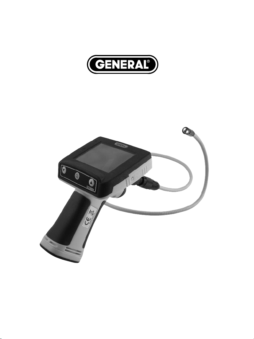
The SeaScope™600 WATERPROOF
VIDEO INSPECTION SYSTEM
USER’S MANUAL
DCS600
Please read this manual carefully and thoroughly before using this product.
Page 2

TABLE OF CONTENTS
Introduction. . . . . . . . . . . . . . . . . . . . . . . . . . . . . . . . . . . 3
Key Features. . . . . . . . . . . . . . . . . . . . . . . . . . . . . . . . . . 4
Safety Instructions . . . . . . . . . . . . . . . . . . . . . . . . . . . . . 4
What’s in the Case . . . . . . . . . . . . . . . . . . . . . . . . . . . . . 5
Product Overview . . . . . . . . . . . . . . . . . . . . . . . . . . . . . . 5
Setup Instructions. . . . . . . . . . . . . . . . . . . . . . . . . . . 6 –9
Install Batteries . . . . . . . . . . . . . . . . . . . . . . . . . 6 –7
Attach Probe . . . . . . . . . . . . . . . . . . . . . . . . . . . . . . 7
Attach Video Cable (Optional) . . . . . . . . . . . . . . . . 8
Installing Accessories . . . . . . . . . . . . . . . . . . . . 8 –9
Operating Instructions . . . . . . . . . . . . . . . . . . . . . . . . . . 9
Specifications . . . . . . . . . . . . . . . . . . . . . . . . . . . . . . . . 10
Maintenance Tips . . . . . . . . . . . . . . . . . . . . . . . . . . . . . 10
Warranty Information . . . . . . . . . . . . . . . . . . . . . . . . . . 11
Return for Repair Policy . . . . . . . . . . . . . . . . . . . . . . . . 11
Page 3

INTRODUCTION
Thank you for purchasing General Tools & Instruments’ DCS600 Waterproof Video Inspection
System. Please read this user’s manual carefully and thoroughly before using the instrument.
™
The DCS600 (The SeaScope
with an IP67 waterproof grip and monitor as well as an IP67 waterproof camera-tipped probe.
The other system is the DCS660 (SeaScope660), a high-end version of the SeaScope600 that
can record videos and still photos.
The SeaScope600’s water tightness makes the system ideal for real-time video inspection of
submerged structures and parts of boats, ships, or bridges. It also extends the scope’s range
of applications to inspecting sewer or water lines carrying running water. Finally, because the
entire unit is impervious to water you can use it freely around water without worrying about
accidentally “dunking” the grip and monitor. No other camera scope with an integral
monitor—other than the SeaScope660—is completely watertight.
The SeaScope600 shares many of the features and benefits of other General Tools &
Instruments video inspection systems. It comes with a 0.39 in. (10mm) diameter, 3.3 ft. (1m)
long flexible-obedient camera-tipped probe with adjustable LED lighting that is in focus from
0.6 to 6 in. (15 to 150mm). Three handy probe tip accessories are also included: a 45° mirror,
a pickup hook and a magnetic pickup.
Because the DCS600 has only three controls (a power on/off button and brightness up and
down buttons), the instrument is very easy to learn to use. Video within the probe’s field of
view is displayed on a large, crystal-clear 3.4 in. (86.4mm) diagonal color LCD. Alternatively,
video can be viewed on an NTSC-format television by plugging a supplied cable into a jack on
the side of the scope’s monitor. Video shown on the monitor can be inverted by pressing both
brightness buttons at the same time. This feature aligns the probe’s field of view with its realworld surroundings and makes it easier to read upside-down serial numbers by flipping them
right-side up.
The SeaScope600 and all of its accessories are packaged in a hard plastic protective case
along with this user’s manual. The unit is powered by four “AA” batteries, which are not
included.
600) is one of only two video inspection systems on the market
3
Page 4

KEY FEATURES
• Makes it possible for a diver or snorkeler to view inspection video under water in real
time. Other “waterproof” inspection systems lack watertight grips and monitors
• Eliminates concerns about accidentally dropping or dunking grip or monitor in water
• Makes it possible to inspect sewer and water lines carrying running water
• Also ideal for marine search and rescue operations
• Grip, probe and monitor are guaranteed leakproof to depth of 1m; all three components
will also resist leaks at depths up to 2m for short periods (1 hour, max)
• Includes 0.39 in. (10mm) diameter, 3.3 ft. (1m) long close-focus camera-tipped probe
with adjustable LED lighting
• Waterproof probe is flexible-obedient, meaning it retains its shape
• 3.4 in. (86.4mm) color LCD makes videos and images large and crystal-clear
• Video shown on monitor can be inverted 180°
• Video Out jack for connection to NTSC television
• One-year warranty
• Powered by four “AA” batteries
SAFETY INSTRUCTIONS
• Do not use the system to inspect environments known or suspected to contain exposed
electrical wiring.
• Do not use it in the presence of flammable or explosive gases.
• Read and understand all of the instructions in this manual before using the system.
• Stay alert, watch what you are doing, and use common sense. A moment of distraction
can result in serious personal injury.
• Do not over-reach. Keep proper footing and balance at all times, especially where water
is underfoot.
• Always use protective eyewear. A dust mask, non-skid safety shoes, a hard hat or
hearing protection may also be appropriate for certain inspection environments and
tasks.
• Do you use the system to perform medical inspections.
4
Page 5

WHAT’S IN THE CASE
The DCS600 and its accessories come in a custom molded plastic case. The instrument itself
has two main components: a pistol grip permanently connected to an LCD monitor, and a
10mm flexible-obedient camera-tipped probe. Also in the case is a large Ziploc plastic bag
containing:
• Three probe tip accessories (a 45° mirror, a pickup hook and a magnetic pickup) in their
own small Ziploc bag
• A composite NTSC video cable with a black mini-plug on one end and a yellow RCA plug
on the other
• This user’s manual
PRODUCT OVERVIEW
Fig. 1 shows the labels and positions of the controls and connectors on the front and side of
the DCS600. Familiarize yourself with the controls’ functions before moving on to the Setup
Instructions.
10
9
Fig. 1. The SeaScope600’s
controls and connector
5
4
3
11
12
8
2
1
14
1
3
15
7
6
1. Video jack (behind waterproof door
on right side of monitor)
2. 3.4 in. (diagonal) color LCD
3. Brightness up (▲) button
4. Power on/off ( ) button
5. Brightness down (▼) button
6. Battery compartment (on bottom)
7. Camera-tipped probe
8. Camera and LEDs
9. Battery Low ( ) LED (red)
10. Power On ( ) LED (green)
11. Triangular hanger hook (on front of monitor)
ACCESSORIES IN THE CASE
12. 45° mirror
13. Pickup hook
14. Magnetic pickup
15. Video cable
5
Page 6

SETUP INSTRUCTIONS
INSTALL BATTERIES
The Seeker600’s battery compartment is accessible from the bottom of the pistol grip
(Fig. 1, Callout 6).
To open the battery compartment,
1. Use a Phillips-head screwdriver to turn the screw securing the compartment’s cover
counterclockwise until the head of the screw pops up, flush with the surface. It is not
necessary to remove the screw.
2. Turn the cover slightly counterclockwise (about 2°) to release it from the grip
(see figure below). Set the cover (still holding the screw) aside.
3. Extract the yellow battery magazine from the grip by pulling on the tab at its end
(see left figure below).
4. Load four “AA” batteries into the magazine, using the polarity markings within it as a
guide (see right figure below).
5. Push the loaded magazine back into the grip (it fits only one way).
6. Retrieve the battery compartment cover and position it 2° left of center, relative to the
bottom of the grip.
7. Pressing on the cover, twist it 2° clockwise until it “catches” the grip housing.
8. Turn the Phillips-head screw clockwise until it is tight, with its head below the surface.
6
Page 7

Notes:
1. Make sure your hands are completely dry before opening the battery compartment.
2. Take extra care to properly secure the cover of the battery compartment after installing
batteries. The battery compartment is one of three places where water could enter the
SeaScope600, potentially causing permanent damage. The other two places are the
connection between the camera-tipped probe and the grip, and the waterproof door
protecting the Video out jack. The remainder of this section explains the proper
procedures for maintaining water tightness at these points.
ATTACH PROBE
The yellow probe must be attached to the grip or the LCD will show a blue screen.
To attach the probe,
1. Slide the metal collar of the grip’s coupling back until it touches the rubber boot on the
grip’s housing.
2. Line up the alignment key on the probe connector with the flat on the coupling (see
photo below).
3. Push the two ends together until they mate.
4. Tighten the connection by turning the collar in the opposite direction of the “REMOVE”
arrow on the collar. Double-check the tightness of the connection; if it is not tight, water
may enter the system later and ruin it.
To detach the probe, perform the attachment procedure in reverse. To loosen the connection
between the two components, turn the collar in the direction indicated by the REMOVE arrow.
grip coupling
Rubber boot
Flat on
Metal collar
Alignment key on
probe connector
7
Page 8

ATTACH VIDEO CABLE (OPTIONAL)
If you wish to view video captured by the
Push latch up
SeaScope600’s probe on an NTSC-format
television, insert the mini-plug end of the
supplied video cable into the Video jack on
the right side of the monitor (Fig. 1, Callout
Slide door
to the
right
1). Plug the yellow RCA connector at the
other end of the cable into the television’s
“Video In” jack.
However, be aware that using the video cable
exposes the DCS600 monitor to water
damage because doing so requires leaving
the waterproof door over the Video jack open.
With the video cable attached, you can still
Video jack
use the probe to perform underwater inspections. But if you accidentally “dunk” the unit, it will
be permanently damaged. Such “accidental damage” is specifically NOT covered by the
SeaScope 600's limited warranty (see p. 11).
To access the Video jack, open the waterproof door covering it (see top photo above) by using
your thumb to push the spring-loaded latch on the door up. Without removing your thumb, use
it to slide the door to the right. Once you see the metal of the door’s hinge at left, use your
index finger to flip the door open and expose the Video jack (see bottom photo above).
When you are done using the video cable to view inspection video on an external monitor,
remember to swing the door shut. The door is only secure and waterproof when you hear its
spring-loaded latch click.
INSTALLING ACCESSORIES
The SeaScope600 comes with three accessories (see left photo on next page) in a Ziploc bag
that attach to the camera-tipped end of the probe. Each accessory has a specific purpose:
• The 45° mirror lets the probe see around corners.
• The pickup hook lets you retrieve otherwise inaccessible items seen by the probe—
for example, a wedding ring accidentally dropped down a sink drain.
• The magnetic hook lets you retrieve lost or dropped metal objects—nuts and bolts,
for example—located by the probe.
To attach an accessory,
1. Hold its metal stem with your thumb and index finger.
2. Slide the accessory—plastic clasp first—past the camera head at the probe tip until
the clasp is in the channel 1/4 in. from the end of the probe.
3. Squeeze the clasp until you hear a click (see top right photos on next page), indicating
that the two halves have joined.
8
Page 9

To detach an accessory,
1. Use the nail of your index finger to unhook the clasp, opening it up.
2. Hold the accessory’s metal stem with your thumb and index finger and slide the
accessory and clasp past the camera head.
3. Put the accessory back in the Ziploc bag it came in.
OPERATING INSTRUCTIONS
Before using the scope for the first time, remove the plastic film protecting the LCD.
Before using the DCS600 for an inspection session, remove the black rubber ring protecting
the probe’s camera head. Remember to replace this ring after each and every inspection
session.
To power on the scope, press the power on/off ( ) button (Fig. 1, Callout 4). This will cause
the green Power on ( ) LED (Callout 10) to light. The LCD will illuminate and show real-time
video from the camera at the tip of the probe.
To increase the brightness of the display, press the ▲ button (Callout 3). To decrease the
brightness, press the ▼ button (Callout 5).
To invert the display, press and hold the ▲ and ▼ buttons at the same time until the video
“flips”. Use this feature to align the probe’s field of view with its real-world surroundings, or to
make it easier to read equipment labels and serial numbers.
Video shown on an external monitor cannot be flipped.
Because the probe is flexible-obedient, you can maneuver it into various positions to aim at
different targets and it will hold its shape.
The DCS600 is designed to be powered for dozens of hours by the same set of four “AA”
batteries. When the batteries’ total charge drops below a preset threshold, the red Battery low
indicator LED (Callout 9) will flash. To replace the batteries, follow the procedure in the
Setup Instructions section of this manual.
9
Page 10

SPECIFICATIONS
Camera-tipped Probe Type/Diameter/Length Flexible-obedient/0.39 in. (10mm);
3.3 ft. (1m)
Probe Minimum Bending Radius 1.77 in. (45mm)
Camera Field of View 54°
Camera Depth of Field 0.6 to 6 in. (15 to 150mm)
Camera Resolution 640 x 480 pixels
Camera Sensitivity 1.8V/lux-sec
Camera Exposure Automatic
Camera Light Source 2 white LEDs
Display Type/Size Color TFT/3.4 in. (86.4mm) diagonal
Display Resolution 320 x 240 pixels
Video Out Resolution/Format 640 x 480 pixels/NTSC
Video Out Cable Length 59 in. (1.5m)
Power Source (4) “AA” batteries (not included)
Power Consumption 400mA max @ 6VDC
Operating Temperature 32° to 113°F (0° to 45°C)
Weight of Instrument and Probe 20.5 oz. (581g)
with Batteries Installed
Dimensions of Carrying Case 13.0 x 10.5 x 4.5 in. (330 x 267 x 114mm)
Weight of Carrying Case with Instrument, 51.2 oz. (1.45kg)
Probe and All Accessories
MAINTENANCE TIPS
The SeaScope600 is not shock-resistant. Do not use it as a hammer or drop it. Also, do not use
the camera-tipped probe to clear debris
If condensation forms inside the lens, let it evaporate before using the system again.
Remove the batteries if planning to store the unit for months or longer.
Properly dispose of used batteries. Exposure to high temperatures can cause batteries to
explode, so do not incinerate them. Some countries regulate battery disposal. Please follow all
applicable rules.
10
Page 11

WARRANTY INFORMATION
General Tools & Instruments’ (General’s) DCS600 Waterproof Video Inspection System is
warranted to the original purchaser to be free from defects in material and workmanship for a
period of one year. Subject to certain restrictions, General will repair or replace this instrument
if, after examination, the company determines it to be defective in material or workmanship.
This warranty does not apply to damages that General determines to be from an attempted
repair by non-authorized personnel or misuse, alterations, normal wear and tear, or accidental
damage. The defective unit must be returned to General Tools & Instruments or to a Generalauthorized service center, freight prepaid and insured.
Acceptance of the exclusive repair and replacement remedies described herein is a condition
of the contract for purchase of this product. In no event shall General be liable for any
incidental, special, consequential or punitive damages, or for any cost, attorneys’ fees,
expenses, or losses alleged to be a consequence of damage due to failure of, or defect in any
product including, but not limited to, any claims for loss of profits.
RETURN FOR REPAIR POLICY
Every effort has been made to provide you with a reliable product of superior quality. However,
in the event your instrument requires repair, please contact our Customer Service to obtain an
RGA (Return Goods Authorization) number before forwarding the unit via prepaid freight to the
attention of our Service Center at this address:
General Tools & Instruments
80 White Street
New York, NY 10013
212-431-6100
Remember to include a copy of your proof of purchase, your return address, and your phone
number and/or e-mail address.
11
Page 12

GENERAL TOOLS & INSTRUMENTS
80 White Street
New York, NY 10013-3567
PHONE (212) 431-6100
FAX (212) 431-6499
TOLL FREE (800) 697-8665
e-mail: sales@generaltools.com
www.generaltools.com
DCS600 User’s Manual
Specifications subject to change without notice
©2010 GENERAL TOOLS & INSTRUMENTS
NOTICE - WE ARE NOT RESPONSIBLE FOR TYPOGRAPHICAL ERRORS.
MAN#DCS600 10/28/11
 Loading...