

THE SEEKER
TM
400 SERIES
WIRELESS RECORDING,
VIDEO INSPECTION SYSTEMS
DCS400
DCS400-05
DCS400-09
User’s ManUal
Please read this manual carefully and thoroughly before using this product.

CONTENTS
Introduction . . . . . . . . . . . . . . . . . . . . . . . . . . . . . . . . . . . . 3
Overview. . . . . . . . . . . . . . . . . . . . . . . . . . . . . . . . . . . . . . . 3
Features . . . . . . . . . . . . . . . . . . . . . . . . . . . . . . . . . . . . . . . 4
System Includes . . . . . . . . . . . . . . . . . . . . . . . . . . . . . . . . 4
Specifications . . . . . . . . . . . . . . . . . . . . . . . . . . . . . . . . . . 5
Safety and Maintenance Instructions . . . . . . . . . . . . 6 - 7
Product Components . . . . . . . . . . . . . . . . . . . . . . . . . . . . 8
One Minute Overview. . . . . . . . . . . . . . . . . . . . . . . . . . . 8
In-Depth Product Overview . . . . . . . . . . . . . . . . . . . . . . 9
Main Controls . . . . . . . . . . . . . . . . . . . . . . . . . . . . . . . . 10
Setting-up the System . . . . . . . . . . . . . . . . . . . . . . . . . 11
Powering the System . . . . . . . . . . . . . . . . . . . . . . . . . . 11
Charging the System . . . . . . . . . . . . . . . . . . . . . . . . . . 12
Probe . . . . . . . . . . . . . . . . . . . . . . . . . . . . . . . . . . . . . . . 13
Monitor . . . . . . . . . . . . . . . . . . . . . . . . . . . . . . . . . . . . . 13
View and Record Images Mode . . . . . . . . . . . . . . . . . 14
Main Menu Mode . . . . . . . . . . . . . . . . . . . . . . . . . . . . . 15
Playback Mode . . . . . . . . . . . . . . . . . . . . . . . . . . . . . . . 16
Taking and Viewing Pictures and Videos. . . . . . . . . . . . 17
Viewing Stored Images and
Uploading Pictures and Videos . . . . . . . . . . . 18 - 19
The Menu Structure. . . . . . . . . . . . . . . . . . . . . . . . . . . . . 20
Shut Down . . . . . . . . . . . . . . . . . . . . . . . . . . . . . . . . . . . . 20
Trouble Shooting . . . . . . . . . . . . . . . . . . . . . . . . . . . . . . . 21
Warranty Information . . . . . . . . . . . . . . . . . . . . . . . . . . . 22

INTRODUCTION
Thank you for purchasing a Seeker™400 Series Wireless, Recording, Video
Inspection System. Please read this user’s manual carefully before using this
product.
All of the scopes in The Seeker400 Series are designed as remote inspection
devices. They can be used to look into tight or inaccessible areas and wirelessly transmit real time video or still images for viewing or recording. The
only difference between The Seeker 400 systems is the diameter of the camera tipped probe. All of the probes are 1m (3.28 ft.) long, flexible-obedient
with three diameters available; 5.5mm, 9mm, and 12mm.Typical applications
include HVAC inspection, automotive inspection, building, construction, machinery, boat, and aircraft inspection.
OVERVIEW
Each
seeKer™system comes with the a pistol grip handle, a removable
LCD display, 1m (3.28 ft.) flexible-obedient probe, 2GB Micro SD card, USB
and video interconnect cables, Li-ion rechargeable batteries, battery charger,
custom molded hard case, instruction manual and 3 year limited warranty.
The system includes a 3.5 in. (88.9mm) diagonal high clarity color LCD and a
camera tipped probe with adjustable LED lights imbedded in the tip. The
DCS400 system with the 12mm diameter probe includes three accessory
tools which can be attached to the probe tip for various applications: the
magnetic tip is used to pick up small metal objects; the mirror tip is used to
view at a 90° angle and the hook is used to grab onto objects. The DCS400
Series wireless function allows the user to detach the LCD from the handle
and view findings remotely up to 32 ft. away. Each 400 Series system operates with built-in rechargeable lithium ion batteries. Each system will interface
with external displays such as a computer, a TV or an LCD panel via USB, SD
card or AV cable. Using General Tools model RCV100 Streaming Video USB
wireless receiver (sold separately), live video can be wirelessly transmitted to
a computer then sent onto the internet for remote conferencing.
3

FEATURES
o
ro
t p
s
du
/
water
is
ich
e wh
b
ro
t p
ien
ed
b
o
le-
, flexib
g
(3.28 ft.) lo
1m
•
d
tan
s
. (88.9m
3.5 in
•
t
m
fro
flip
d
an
o
• 4x zo
• Both moni
g
ar
ch
tem
s
• Sy
s
ju
Ad
•
clear inspection
View r
•
o
t
Up
•
NTSC
•
a
USB
•
ce of 5 menu languag
Choi
•
ugue
t
or
P
nal
o
pti
O
•
e
r
he
t
T
S
Y
S
om
Cust
•
DCS4
•
A 1m (3.28 ft.) Long, Flexible-Obedient Probe
•
Detachable, Wireless Monitor with Flip-out Stand and Built-in Magnets
•
2GB Micro SD Memory Card
•
USB and Video Interconnect Cables
•
2 “Li-ion” Rechargeable Batteries with AC Adapter/Charger
•
The 12mm System (DCS400) comes with 3 Accessory Tools:
•
(45° Mirror, Magnetic Pick-Up, Pick-Up Hook)
One-into-Two Charging Cable
•
Instruction Manual
•
Three Year Limited Warranty
•
n
s
ard
al T
n
o
iag
) d
he unit
u
o
featu
m
at th
ed
co
table
sult
e
hour
3
PA
or
vid
nd
se
probes
of
h
c
a
m
fo
tan
t s
tor a
e s
es
m
ED
L
s in re
s
c
L
o
e
he
t
rem
r
re •
nd ha
am
co
lig
of
ompa
int
or pro
c
d
a
vid
o
m
h
l-
e
a
e v
t
o
th
n
180° im
ndl
e tim
lete with
p
in
ts
ime
t
(AVI)
o
e
ible
t
onne
c
r
be extens
a
r
me
iewing
e b
use
e
e u
ide
s
record
,
EM INCLUDES
se
Ca
d
r
Ha
d
e
Mold
le
nd
Ha
ip
Gr
istol
P
0
0
L
T-
F
ack o
ag
r
g
in
s
b
th
a
c
t
c
es: Engl
CD wireles
10m
o
t
up
e m
f th
featu
e flip
rge
ha
c
e
clu
e in
th
ies
atter
th
f
o
tip
e
eo a
vid
e
r
a
s
le
b
sh, F
i
are avai
ns
o
i
:
lo
co
s
.
ft
32
(
allo
r
ito
n
o
re
-i
Li
e
l
b
a
n
o
ed
d
ar
ch
d
an
e
b
ro
p
e
ur
t
p
a
c
nd
d
e
lud
inc
rench, Spanis
e f
abl
l
n
o
m
r
away
)
w h
on ba
to
e–in
er
g
m
illu
save st
/
e
or each s
be d
can
r
ito
bedded m
m
I
.
free o
-
s
d
an
s w
e
ri
tte
ar
ch
two
-
ar
d
ate
in
ill photos (JPEG)
h, Chinese and
tem to extend
s
y
p
c
hi
in
g
p
s
k
to
f
etach
ag
atio
er
h c
cab
g
aces
a
IP67
ed
net
n
n be
le.
fo
s
.
r
4

SPECIFICATIONS:
PISTOL GRIP HANDLE:
Transmission Range: Up to 10m (32.8 ft.) clear field
Transmission Frequency: 2.4GHz
Handle Dimensions: 8.5 x 6.5 x 1.9 in. (215 x 165 x 50mm)
Weight: 15 oz. (425g)
Power Source: 1 Lithium-Ion rechargeable battery (included)
CAMERA TIPPED PROBES:
12mm (0.47 in.) diameter (
Resolution: 320 x 240 Pixels (NTSC), 704 x 576 pixels (PAL)
Depth of Field (DOF): 30 to 100mm (1.2 to 3.94 in.)
Field of View: 60°
Probe Length: 1m (3.28 ft.)
Optional 12mm Probe Extensions: 1m, 2m, 3m (3.28 ft., 6.56 ft., 9.84 ft.)
Maximum Extended Probe Length: 5m (16 ft.)
9mm (0.35 in.) diameter (
Resolution: 320 x 240 Pixels (NTSC), 704 x 576 pixels (PAL)
Minimum Focus Distance: 10mm (0.5 in.)
Field of View: 60°
Probe Length: 1m (3.28 ft.)
Optional 9mm Probes: 1m, 2m, 3m (3.28 ft., 6.56 ft., 9.84 ft.)
5.5mm (0.20 in.) diameter (
Resolution: 320 x 240 Pixels (NTSC), 704 x 576 pixels (PAL)
Minimum Focus Distance: 10mm (0.5 in.)
Field of View: 60°
Probe Length: 1m (3.28 ft.)
Optional 5.5mm Probes: 1m, 2m, 3m (3.28 ft., 6.56 ft., 9.84 ft.)
DETACHABLE, WIRELESS MONITOR:
Display: 3.5 in. (88.9mm) diagonal TFT LCD Color Screen
Video/Image Resolution: 320 x 240 Pixels (AVI)
Dimensions: 3.9 x 3.3 x 1.0 in. (100 x 85 x 25mm)
Weight: 6.1 oz. (172g)
Power Source: 1 Lithium-Ion rechargeable battery
CE/FCC Approvals: Yes
DCS400
DCS400-09
)
DCS400-05
)
)
5

SAFETY INSTRUCTIONS
• Read and understand all instructions prior to any operation.
• Do not remove labels from the product.
• Do not operate the product in the presence of flammable/explosive gases.
• Do not use the product around corrosive chemicals which can damage sensitive tips.
• Never spill liquid of any kind on the video display units as this may cause
damage.
• Do not use the device for personal or medical use.
GENERAL INFORMATION AND
MAINTENANCE INSTRUCTIONS
• Do not insert camera probe using excessive force.
• Do not use the probe camera head to clear path-ways or clogged areas.
• Do not exceed the maximum 2” (50mm) bending radius for the probe.
• The camera head and the probe are waterproof but the handle and the
removable display unit are not.
• Not intended for use in areas with exposed AC wiring.
• When the camera scope handle battery is low, the charging light on the handle will light up (red).
• When the removable monitor battery is low the “(empty battery icon)” will
show up on the screen.
• Should the unit freeze up, press the reset button or power off the unit.
• The camera handle and monitor can only be completely disconnected from
the mains by unplugging the ac adapter.
• Charge the batteries every three months when not used for long periods.
• To clean the instrument use mild soap and a soft cloth.
6

BATTERY PRECAUTIONS
• Please use the included factory AC power adapter. Using other AC adaptors
may damage the instrument and void the warranty.
• Full battery charging and discharging is recommended on first use
• The charging time should not be greater than 12 hours for the first few
charging cycles. This process will maximize battery capacity.
• The discharging time will vary depending on which functions are being used.
• Monitor and camera handle use Lithium-Ion rechargeable batteries. Do not
open battery compartments unless battery replacement is necessary.
• Dispose of the batteries properly. Please follow all applicable regulations.
• Discarding a battery into fire may cause an explosion.
FCC INFORMATION
This device complies with part 15 of the FCC Rules.
7
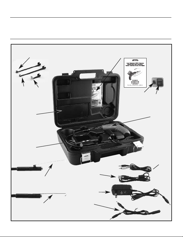
PRODUCT COMPONENTS
The
SEEKER™400
Wireless, Recording, Video Inspection System
CHAPTER 1: A ONE MINUTE OVERVIEW
Fig.
1
#8
Magnetic Retrieval Tip
12mm only
#1
Instruction Manual
#2
Plastic
Case
#7
Hook
Retrieval
12mm only
Compartment
Detachable
Wireless Monitor
Attaching the Accessory Tips
Accessory Tip Attached
45º Mirror
12mm only
#5
Accessory
#11
#10
12mm only
#10
12mm only
#6
8
#14
USB Connecting Cable
#12 Charger
#13
1 into 2
Charging Cable
#3
2GB Micro
SD Card
Probe & Pistol Grip
Handle
#15
Video Cable
#4
SD Card
Adapter
#11

Inside the case in Fig.1 you’ll find several key components of the Seeker system stored in the top half of the carrying case. One is a plastic bag that is
taped to the inside of the top. Inside it are the unit’s instruction manual (#1) and
a small plastic case (#2) containing a Micro SD memory card (#3) and a Micro
SD to full size SD card adapter (#4). At the lower left of the lid there is a separate compartment (#5) housing applicable accessories. The 12mm DCS400
system contains 3 accessory tips, a 45 degree mirror (#6), a hook retrieval tip
(#7), and a magnetic retrieval tip (#8). Each tip can be attached to the camera
head by snapping it onto the flats on either side of the head near its end (#10).
The bottom of the carrying case securely houses the Video Inspection System
(#11), along with its charger (#12), the split output charging cable (#13), and
two connecting cables (#14, #15) for uploading or viewing stored images.
The charger is a 120-volt/240-volt AC adapter which interfaces with the oneinto-two charging cable (#13). The connecting cables include a USB interface
cable (#14) and a video cable (#15) for connecting the system to a computer or
remote monitor.
CHAPTER 2: IN-DEPTH PRODUCT OVERVIEW
MAIN COMPONENTS
Fig.2
LED Light
#4
#3
Camera
#4
LED Light
#5
Black Rubber
Protective Cover
#6
Detachable and
Wireless Monitor
12mm Probe Tip
#2
1 Meter Long
Probe
9mm Probe 5.5mm Probe
#1
Pistol Grip
Handle
The Seeker system has three main components (Fig.2): first is the pistol grip
handle (#1) which controls the on/off functioning of the probe as well as the
9

LED brightness. Attached to the handle is the 1 meter long probe (#2) which
contains the camera (#3) and the LED lights (#4) in the leading end under the
black rubber protective cover (#5). Finally there’s the removable and wireless
LCD monitor (#6) which controls all of the scope’s functioning and recording
controls. The LCD monitor can be attached to the handle or removed and used
wirelessly.
MAIN CONTROLS
The main controls (Fig.3) are below the screen at the front bottom of the
display and consist of five buttons. A central black MENU button is (#6) straddled right and left by two yellow buttons (#7, #8) which are straddled by two
more black buttons (#9, #10). Each of the buttons has multiple functions and
their operation depends upon what mode you are in.
Fig.3
View and
record
images
mode
Main
Menus
Playback
mode
10
#9
Left Black Left Yellow Menu Right Yellow Right Black
Button Button Button Button Button
Take a
photo
Scroll left
through the
3 main
Menus
Scroll left
through
stored
images
#7
Rotate
Screen
Image
Move up
within menu
structure
Increase Data
and time
Play, pause
and resume
video
#6
Switch to
Main
Menus
mode
Select or
set menu
item
Access playback
menu
Select image
playback
Select open folder
#8
Magnify
Image
Move down
within menu
structure
Decrease
Data and time
Stop video
playback
View stored
images and
folders
#10
Shoot
Video
Scroll right
through the
3 main
Menus
Scroll right
through the
stored
images

SETTING-UP THE SYSTEM
Remove the pistol grip handle with attached probe from the
hard case. Then remove the wireless LCD
monitor. Attach the
monitor to the handle
by aligning the signal
connector slots (#1) on
the monitor with the
dual tabs (#2) on the
top of the handle
(Fig.4). Slide the monitor to the left until it securely engages the locking buckle clip (#3). (To remove the
monitor you need to depress the buckle clip and slide the
monitor to the right).
You are now ready to power ON the system or to charge the
system. When using the system don’t forget to remove the
camera’s protective cover (Fig.2 #5).
#3 Locking Buckle Clip
#1
Connector
Slots
#2
Dual
Tabs
Fig.4
Slide
Pistol Grip
Handle
POWERING THE SYSTEM
To turn the monitor ON simply press the ON/OFF button on the top of the
monitor (Fig.5).
Fig.5
The pistol-grip handle (Fig.6) has a yellow thumbwheel
for ON/OFF control of the camera and to adjust the
brightness of the white LED lights at the end of the
camera head.
Yellow Thumbwheel up to Turn On and down
to turn off Probe, Camera and LED Lights
Fig.
Power Button
to Turn
Monitor
ON/OFF
6
11

CHARGING THE SYSTEM
Fig.7
Slide
Monitor to
the right
to remove
from handle
#2
Bi‐Colored
Charging Light
on Handle
Charging Port
on Handle
Both the LCD display and the pistol-grip handle have internal Lithium ion
rechargeable batteries which can be charged separately or at the same time.
(Fig.7)
CHARGING THE HANDLE
To charge the handle, insert one of the split cable plugs from the charger interface cable into the jack on the right side of the handle (#1). There is a
bi-colored charging light just above the thumbwheel to the right (#2): it glows
green when the unit is fully charged, or red when charging.
CHARGING THE MONITOR
To charge the monitor, insert the other split cable plug into the right side port
displaying the charging symbol (#3). The monitor charger jack also has a bicolored charging light (#4) that glows red when the unit is being charged and
green when fully charged.
12
#4
Bi‐Colored
Charging Light
on Monitor
#1
#2
Bi‐Colored
Charging Light
on Handle
#3
Charging Port
on Monitor
Charging Cables Attached to Handle
and Monitor

PROBE
Each SEEKER 400 Video Inspection System is supplied already connected to
a one-meter-long flexible-obedient probe. The SEEKER 400 System has a
slim 12-millimeter diameter tip. The SEEKER 400-09 system is supplied with
an ultra-slim 9-millimeter diameter probe and the SEEKER 400-05 system is
supplied with an superslim 5.5-millimeter diameter probe. Whichever SEEKER
400 system you’re using the other probes are available options and are interchangeable with the base unit. Note that the camera head and probe cable
are waterproof, as are the extensions, which, if firmly connected, will make the
entire probe waterproof.
To remove the supplied probe from the handle (Fig.8), turn the collar that con-
nects them in the direction shown on its surface — counterclockwise — and
pull the probe straight out from the
handle. To re-attach the probe, or
attach the extensions, reverse the
process, making sure that the
“alignment key” at the end of each
probe lines up with the flat on its
coupling. Tighten the connections
by turning the collar clockwise.
Fig.8
Keyed Ends
MONITOR
The other main component of the Seeker 400 system is its
3.5-inch color LCD monitor (Fig.9). Because the monitor can
communicate wirelessly with the base unit, it can
show what the probe sees even when the two units
are located as far apart as 10 meters, or 32 feet.
When the monitor is attached to the pistol-grip handle, the two units communicate via hard-wired connections, rather than wirelessly. This improves the
quality of the still images and video captured by the
system.
Fig.9
13

The right side of the LCD monitor (Fig.10) houses the controls and connections
you will use to view, record and upload your images as well as charge the unit
(Fig.7). To start with, the button on the top right of the unit (#1) performs two
functions. When it is pushed and held for 3+ seconds, it turns the display ON
and OFF. When it is pressed only briefly (after the unit has been powered up),
it toggles the unit’s operating mode between live viewing and recording with
playback of pictures and videos.
Fig.10
#2
Video Out
#3
USB Port
#4
SD Memory
Card
#5
Monitor
Charging Port
#6
Bi-Colored
Charging Light
#1
Power Button
(on top)
On the right side of the monitor are the jacks needed to plug in the video
cable (#2) “Video out”, the USB cable (#3) , the Micro SD memory card (#4),
the charging port (#5), and the bicolored charging light (#6).
VIEW AND RECORD IMAGES MODE
In the “live viewing/recording” mode the controls have the following functions:
1. Pressing the left black button (#9) takes a still picture (in .jpg format).
2. Pressing the right black button (#10) begins and ends the video recording.
3. Pressing the left yellow button (#7) inverts the screen image 180º.
4. Pressing the right yellow button (#8) enlarges the screen image on the
display by up to 4 times. Each time you press this button, the image gets
larger by a factor of 0.2 up to 4x. A readout on the bottom of the display indicates the current zoom level.
14

MAIN MENUS MODE
Pressing the center “MENU” button (#6) will bring you to a series of menus
(Fig.11) used to set-up the system. These include: the Advanced Settings
Menu, the Auto Capture Menu and the Time/Date Menu.
You can scroll right and left to these 3 menus by using the right and left black
arrow buttons (#9, #10). Within each top level menu are sub menus and you
can scroll up and down within all of these menus using the two yellow buttons (#7, #8). To make a selection within the sub menus, press the menu button (#6). To escape the sub menus, press either of the right and left black
buttons (#9, #10). To escape the menu structure, select the EXIT listing at the
bottom of each menu and press the MENU button. Please refer to chapter 5
“The Menu Structure” for further information.
Fig.11
#9 #10#7
#6 #8
15

PLAYBACK MODE
Once you are in the playback mode (after
briefly pressing the ON/OFF button on the
top of the monitor), the controls have the following functions:
1. Pressing the left or right outer black buttons (#9 or #10) scrolls through your set of
stored pictures and video one step either
left or right in their order of capture.
2. Pressing the left yellow button (#7) when
a projector icon is on-screen controls the
playing of that particular video.
3. Pressing the right yellow button (#8) controls the file menu of the pictures and
videos. The first press displays thumbnails
of the media captured so far (Fig.12).
Pressing it again reveals the folder structure storing your pictures and video
(Fig.13). Each folder handles only so much
data so there will be multiple folders depending on how many images you have
stored. Pressing the MENU button (#6)
after selecting a folder will open that
folder. Pressing the MENU button again
after selecting an image will open that picture or video for viewing.
4. Finally, by pressing the center Menu button (#6) (while in normal ‘playback’ mode)
you will open the ‘Playback’ menu (Fig.14)
where you can format and delete the
images.
16
Fig.12
Fig.13
Fig.14

CHAPTER 3: TAKING AND
VIEWING PICTURES AND VIDEOS
Before you are able to take any pictures, make sure that
the handle grip and display units are both charged,
turned on and that the micro SD memory card is securely plugged into the slot on the right of the display.
Make sure that the gold contacts are facing front and
inserted first. When the memory card is present, the X
will no longer appear over the blue SD icon in the upper
left corner of the display (Fig.15).
To take a picture (in other words, capture a still image),
first aim the tip of the probe at the area of interest then
press the black button with the camera icon at the far
left below the display. You’ll note that a yellow icon of a
camera briefly appears in the middle of the display
(Fig.16) to confirm that a picture was taken.
Similarly, to start video recording, press the right black
button below the display. The blinking “REC” symbol
(Fig.17) appears at the top left of the display. To the right
of this is a stopwatch that counts up from zero to indicate the duration of the video captured. To stop recording, again press the black button with the projector icon.
Each of the yellow buttons below the display has
a second function. The left button (Fig.11 #7) will invert
the image on the screen and the right button (Fig.11 #8)
will zoom in and out up to 4x.
Note that either a yellow camera icon (Fig.18) indicating a still picture or an orange projector icon (Fig.19) in-
dicating a video appears in the upper left corner. Your
pictures and video will appear in the sequence that you
took them. To review your pictures use both right and
left black buttons below the display to move left and
right, just as you would with a digital camera. When an
orange projector icon appears you can play the video
Fig.15
Fig.1
Fig.17
6
17

by pressing the left yellow button. When videos are
being played back, a white film strip icon appears in
the upper left of the display, next to the timer (Fig.20).
To pause or resume playback again press the yellow
button with the up arrow. Pressing the yellow button
on the right with the down arrow will cancel the playback and bring you back to the main menu.
To return back to live camera mode again briefly press
the on/off button. Pictures and video can viewed simultaneously on a monitor using the video cable or
uploaded to a computer using the USB cable or the
Micro SD card with or without the adapter.
Fig.18
Fig.19
CHAPTER 4:
VIEWING STORED IMAGES
AND UPLOADING
Fig.20
PICTURES AND VIDEOS
You can view your stored images on the scopes monitor, on a computer
screen, on a remote monitor, or on a TV. Just a note about format: still image
pictures are initially stored on the DCS400 as JPEG files and video is stored
as AVI files. To send live video over the internet using Skype, use General
Tools RCV100 Streaming Video USB wireless receiver (sold separately).
To connect to a computer you can either use the USB cable connector which
has a standard A-Type connector on one end and a Mini-B Type connector on
the other end or you can use the Micro SD card to transfer the images.
To connect to a remote monitor or a TV you need to use the video cable. The
video cable has a black mini-plug connector on one end and a yellow RCA
plug on the other.
For a computer upload using the USB cable simply insert the Mini-B Type
connector into the small USB slot on the right side of the scopes monitor
which has a USB icon above it. Next, insert the larger A-Type connector into
18

a USB port of your computer. Once both plugs have been inserted, the
DCS400 monitor’s screen will go all blue, except for the letters “MSDC” in the
center.
Once this has occurred, you can access the stored files through the normal
functioning of your computer. The DCS400 will appear as a remote storage
device in your computer’s menu.
To just view your pictures on a remote device you use the video cable. Simply insert the black mini-plug into the mini-jack on the right side of the
DCS400 monitor labeled “Video out”. Next, insert the yellow RCA plug into the
yellow jack of the remote TV or monitor labeled “Video in”. Put the unit into
playback mode by briefly depressing the on/off button on its top. When you
do this, the scopes monitor goes dark and the remote monitor will display
the images. If you’re using a TV as your remote device you will need to tune
to the “video in” channel.
You then use the black left and right buttons (Fig.3 #9 & #10) below the display of the DCS400 monitor to scroll through your media.
Finally, if your computer or remote monitor is equipped with a slot for a standard SD or Micro SD memory card, you can view your saved media without
using any of the cables. To do so, remove the Micro SD card from the scopes
monitor by first pushing it in then releasing it, letting it pop out. If the slot on
your computer can accept a Micro SD card directly you can simply plug it in.
If the slot is the wider, standard SD slot you can use the SD card adapter that
was supplied in the same plastic case as the Micro SD card. Insert the Micro
SD card into the open side of the adapter so its gold contacts face the same
way as the contacts on the opposite side. Then insert the adapter, contacts
first, into the slot on the computer or remote monitor.
If you’ve done this on a computer, you can now use your computer’s normal
functioning to locate and view the captured pictures and video. The media
files will me found in a folder labeled “YCKC.” At this point, it’s a good idea
to copy the YCKC folder to your computer’s hard drive. Once you have stored
the pictures and videos on your computer, you can edit, delete, or e-mail any
of them, just as you would any digital file.
19

CHAPTER 5: THE MENU STRUCTURE
ADVANCED SETTINGS
Tuner Channel
Ch1
Ch2
Ch3
Ch4
Exit
Photo Quality
High Quality
Standard Quality
Low Quality
Exit
Movie Quality
QVGA
D1
Exit
TV Output Standards
NTSC
PAL
Exit
EXIT
AUTO CAPTURE
Auto Capture
On
Off
Exit
Manual Capture
Photo 1
Photo 3
Movie 5
Movie 10
Exit
File Overwrite Set
On
Off
Exit
EXIT
SET TIME/DATE
Set Time/Date
YYYY/MM/DD
HH:MM:SS
YY/MM/DD
Photo Time Stamp
On
Off
Exit
Movie Time Stamp
On
Off
Exit
Load Default
Yes
No
EXIT
PLAYBACK MENU
File Delete
Single
Delete
Yes
No
All
Delete
Yes
No
Cancel
Format
Yes
No
EXIT
CHAPTER 6: SHUT DOWN
To shut down the monitor, hold the ON/OFF button for 3 or more seconds. A
“Goodbye” screen will appear.
To shut off the probe and handle simply rotate the thumbwheel backwards
until it clicks off.
We hope that you’ll have years of great service from your Seeker400 Wireless,
Recording, Video Inspection System.
20

TROUBLE SHOOTING
Problems Causes Solutions
Will not
charge
The screen is
on but without
image or shows
“No Signal”
LEDs on the
camera head
are dim at max
brightness, display changes
from black to
white, color
display turns
itself off after
a period.
Adapter didn’t make a
good connection with
product.
The connector or cable
is broken.
Dead battery
1. Different channel
set between the
grip and screen.
2. The probe is loose.
3. Stains on the
camera head.
Low battery
Please check and try again.
Replace and try again.
Ask a technician to replace the battery.
Set the same channel.
Check and connect again.
Check if stains exist.
Use adapter for charging.
The product
won’t turn on.
Abnormal
display or
invalid keys.
The circuit is in
protection status.
Low battery
Dead battery
Interference to the
screen or voltage
fluctuation.
Press reset or use adapter for charging
to release.
Use adapter for charging
Ask a technician to replace the battery.
Please use the reset button
inside the hole below the
stand base.
21

WARRANTY INFORMATION
THREE YEAR LIMITED WARRANTY
General Tools & Instruments (General) DCS400 Wireless, Recording, Video
Inspection System is warranted to the original purchaser to be free from defects
in material and workmanship. Subject to certain restrictions, General will repair
or replace this instrument, if after examination, it is determined by General to be
defective in material or workmanship for a period of three years.
This warranty does not apply to damages that General determines to be from an
attempted repair by non-authorized personnel or misuse, alterations, normal
wear and tear or accidental damage. The defective unit must be returned to General Tools & Instruments or a General authorized service center, freight prepaid
and insured.
Acceptance of the exclusive repair and replacement remedies described herein
is a condition of the contract for purchase of this product. In no event shall General be liable for any incidental, special, consequential or punitive damages, or
any cost, attorneys fees, expenses, losses alleged to be as a consequence of
any damage due to failure of, or defect in any product including, but not limited
to, any claims for loss of profits.
22

NOTES
________________________________________________________________________
________________________________________________________________________
________________________________________________________________________
________________________________________________________________________
________________________________________________________________________
________________________________________________________________________
________________________________________________________________________
________________________________________________________________________
________________________________________________________________________
________________________________________________________________________
________________________________________________________________________
________________________________________________________________________
________________________________________________________________________
________________________________________________________________________
________________________________________________________________________
________________________________________________________________________
________________________________________________________________________
________________________________________________________________________
________________________________________________________________________
23

GENERAL TOOLS & INSTRUMENTS
-
80 White Street • New York,NY10013
3567
PHONE (212) 431-6100 • FAX (212) 431-6499 • TOLL FREE (800) 697-8665
e-mail: sales@generaltools.com www.generaltools.com
Specifications subject to change without notice NOTICE - NOT RESPONSIBLE FOR TYPOGRAPHICAL ERRORS.
DCS400 User’s Manual
©2011 GENERAL TOOLS & INSTRUMENTS
12/29/11
 Loading...