


THE SEEKER
THE SEEKER
™
200 SERIES &
™
300 SERIES
VIDEO INSPECTION SYSTEMS
DCS200
(shown)
DCS300
(shown)
DCS200/DCS200-09/DCS200-05
DCS300/DCS300-09/DCS355
USER’S MANUAL
Please read this manual carefully and thoroughly before using this product.

CONTENTS
Introduction . . . . . . . . . . . . . . . . . . . . . . . . . . . . . . . . . . . 3
Features . . . . . . . . . . . . . . . . . . . . . . . . . . . . . . . . . . . . . . . 3
Probe Tip Accessories . . . . . . . . . . . . . . . . . . . . . . . . . . 4
Product Overview . . . . . . . . . . . . . . . . . . . . . . . . . . . . . . 4
Battery Installation . . . . . . . . . . . . . . . . . . . . . . . . . . . . . 5
Disconnecting and Reconnecting the Probe . . . . . . . 6
Installing the Accessories . . . . . . . . . . . . . . . . . . . . . . . 6
Operating Instructions . . . . . . . . . . . . . . . . . . . . . . . . . . 7
Basic Operation . . . . . . . . . . . . . . . . . . . . . . . . . . . . . . . 7
Image Rotation and Zoom Operation . . . . . . . . . . . . . . 7
Camera Tipped Probes . . . . . . . . . . . . . . . . . . . . . . . . . 8
Operating Precautions . . . . . . . . . . . . . . . . . . . . . . . . . . 8
Maintenance Instructions . . . . . . . . . . . . . . . . . . . . . . . 9
Trouble Shooting . . . . . . . . . . . . . . . . . . . . . . . . . . . . . . . 9
Specifications . . . . . . . . . . . . . . . . . . . . . . . . . . . . . . . . . 10
Warranty Information . . . . . . . . . . . . . . . . . . . . . . . . . . 11
Return For Repair Policy . . . . . . . . . . . . . . . . . . . . . . . 11

INTRODUCTION
The Seeker™200 and Seeker 300 Series Inspection Systems have
been designed as a user friendly and economical way of viewing
hidden problems and increasing productivity. Each system has a
high clarity color LCD for clear imaging. The differences between the
3 systems are the size of the screen and the diameter of the probes.
The Seeker
Seeker
head is housed inside the tip of each probe with adjustable white
LED lights, which helps you to see in those dark gaps and holes.
These video inspection systems have the advantage of clear images,
easy operation and portability. They are widely used in applications
such as HVAC/R building, aviation and vehicles maintenance.
™
200 Series has a 2.4" (60.9mm) diagonal screen and the
™
300 Series has a 3.5" (88.9mm) diagonal screen. The camera
FEATURES
• DCS200 Series: 2.4" (60.9mm) Color LCD Screen
for a crystal clear image
• DCS300 Series: 3.5" (88.9mm) Color LCD Screen
for superb clarity and viewing effect
• Camera-tipped probes are flexible and strong with built-in
adjustable LED lighting, and are slim enough to perform
automotive engine check-up
• Flexible probes retain configured shape to suit
different inspection needs
• View findings instantaneously
• 2X digital zoom and 180º image rotation
• Optional probes of different diameters and lengths
• All probes are interchangeable between DCS100, DCS200,
DCS300 and DCS400 series
3
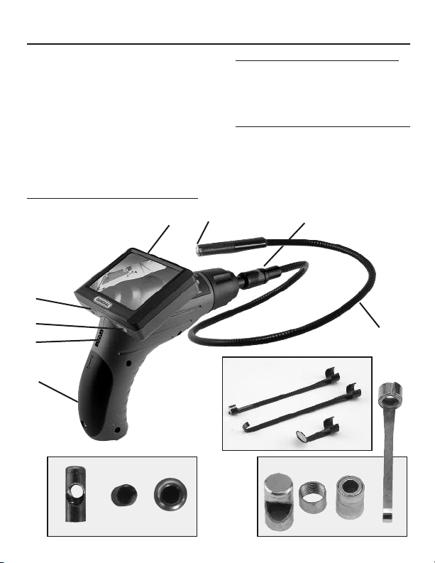
PRODUCT OVERVIEW
A. LCD Screen
B. Image Rotation
C. Image Zoom
D. Battery Compartment
E. ON/OFF Switch /
LED Lighting Intensity
F. Probe Connector
G. Probe
H. Camera Head
12mm Probe accessories
I. Magnetic Tip
J. Hook Tip
K. 45º Mirror Tip
B
H
A
5mm Probe accessories
L. Mirror
M. Thread Protector
N. Ball Guide
9.0mm Probe accessories
O. Mirror
P. Thread Protector
Q. Magnet
R. Hook
F
Fig. 1
C
E
12mmProbeaccessories
D
LNM
Fig. 2
4
5.5mmProbeaccessories
ORQP
9.0mmProbeaccessories
G
I
J
K

BATTERY INSTALLATION
1. Use the included Phillips screwdriver to open the screw on
the battery compartment cover (See Fig. 3).
2. Insert one “9V” alkaline battery into the battery
compartment (See Fig. 4). Close the battery cover and fasten
the screw.
Battery
Battery
Compartment
Cover
Screw
Compartment
Fig. 3
Fig. 4
PRECAUTIONS!
• Remove the battery before storing the unit for a long
period of time.
• Be sure to install the battery with the correct polarity as
indicated in the battery compartment.
• Properly dispose of the batteries. Exposure to high
temperatures can cause the batteries to explode.
Do not dispose in fire. Place tape over the terminals
to prevent direct contact with other objects. Some
countries have regulations concerning battery disposal.
Please follow all applicable regulations.
5
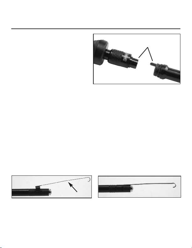
DISCONNECTING AND
RECONNECTING THE PROBE:
All of the probes from these
3 systems are interchangeable and in the case of the
12mm dia. probe, you can
add extensions to extend the
camera tip up to 16 ft. (5m).
To disconnect the probe
from the display unit, twist
the retaining collar counter clockwise several turns and pull
away from the unit. Then pull the probe straight away from the
unit. To reconnect the probe or probe extensions to the
display unit, make sure the keyed ends are properly aligned
(See Fig. 5). Once they are aligned, tighten the retaining collar
by twisting it clockwise.
INSTALLING ACCESSORIES: (From Fig. 2)
12mm dia. tip:
tip and magnetic tip. All are attached to the camera head
the same way. As shown in Fig. 6, slip the semicircle end of
the accessory over the flats of the camera head and then
press down to fix as shown in Fig. 7.
Fig. 6
5.5mm dia. tip and and 9.0mm dia. tip: Each of the three
accessories screw directly onto the top of the probe.
The thread protector is used when the mirror or the ball guide
are not attached.
The three accessories include mirror tip, hook
Fig. 7
Accessory
KeyedEnds
Fig. 5
6

OPERATING INSTRUCTIONS
LCDScreen
RotationButton
ZoomButton
ON/OFF
BRIGHTNESS
Fig. 8
BASIC OPERATION:
To turn the unit on, hold the LCD display unit facing you
(See Fig. 8). Roll the on/off/brightness switch away from you
to turn the power on. The switch then acts as a dimmer for the
LED’s in the tips of the probes. Activating the switch also
illuminates the LCD screen. Note: There is no auto off. Make
sure to roll the switch back towards you until it clicks to turn
off the unit after use.
IMAGE ROTATION AND ZOOM OPERATION
The left button on the back of the monitor housing is the
“Image Rotation” button. Press once to flip image (seen in the
LCD monitor) by 180º. The right side button is the “Zoom”
button. Press this multiple times to achieve a full 2X enlargement of the image (seen in the monitor).
7

CAMERA TIPPED PROBES
LED
Camera
12mmprobetip
LED
Camera
LED
LED
5.5mmprobetip
LED
Camera
LED
LED
LED
9mmprobetip
LED
LED
OPERATING PRECAUTIONS!
• Maximum bending radius is 2"; exceeding this may damage
the probe.
• Do not use the probe (camera head) to clear pathways or
clogged areas.
• The hand-held display unit is NOT waterproof and may
become damaged when exposed to water. The camera head
of the probe and its cover are waterproof, but NOT acid-proof
or fireproof. Exposure to these materials will damage the
camera heads protective plastic. Avoid submerging the
camera head into corrosive solvents. Do not expose to high
temperatures.
• Do not place the camera head or probe into areas that may
contain exposed live electrical wires.
For construction: When inspecting inside walls, make sure
there are no exposed live wires, if you are not sure, shut off
the circuit breaker to the whole area before probing with
the scope.
For automobile engine inspections: Be sure the automobile is
not running during inspection. Metal and liquid under the
hood may be hot. Don’t submerge the camera head in oil
or gasoline.
8

MAINTENANCE INSTRUCTIONS
• Service must be performed by qualified repair personnel.
• When servicing this product, only use identical replacement
parts. Use of unauthorized parts or failure to follow
maintenance instructions will void the warranty.
• Disassembling this unit will void the warranty.
• Do not use acetones to clean this product. Use mild soap
and a soft cloth to clean. Gently clean the LCD with a dry
cloth.
TROUBLE SHOOTING
Symptoms Reasons Solutions
Display is on,
but no image
• LED’s on the camera
head are dim at
max bright
• Color display
changes to
black and white
• Color display turns
itself off after a
period of time
The product
won’t turn on
The probes
connection to the
main grip is loose
Cameras head
covered by
debris or safety
cap is on
Low battery
Dead battery
Tighten connection
and try again
Clean camera head
Replace battery
Replace battery
9

SPECIFICATIONS
CAMERA TIPPED PROBES
12mm 9mm 5.5mm
Resolution (pixels NTSC) 320 x 240 320 x 240 320 x 240
Resolution (pixels PAL) 704 x 576 704 x 576 704 x 576
Minimmum Focus Distance 100mm (4") 10mm (0.5 in.)
Field of View 60º 60º 60º
DCS200 2.4" (60.9mm) TFT/LCD
Image Display
Resolution 320 x 240 pixels
Probe Length (supplied) 39" (1m)
Light Source Adjustable LED
Power Source One “9V” alkaline battery
Estimated Battery Life About 2.5 hours
Operating Temperature 32° to 113°F (0° to 45°C)
Operating Humidity 5% to 95%RH non-condensing
Storage Temperature -4° to 140°F (-20° to 60°C)
Body Dimensions
Weight Approx. 16 oz. (454g)
Series
DCS300
Series
DCS200 8.5 x 4.6 x 3.2 in.
Series (215 x 156 x 80mm)
DCS300
Series (215 x 156 x 96mm)
3.5"(88.9mm) TFT/LCD
2x digital zoom
180º image rotation
≤85% (w/o battery)
8.5 x 4.6 x 3.8 in.
10

WARRANTY INFORMATION
THREE YEAR LIMITED WARRANTY
The General Tools & Instruments (General®) DCS200 Series and DCS300 Series
digital video Inspection Systems are warranted to the original purchaser to be free
from defects in material and workmanship for a period of three (3) years. Subject
to certain restrictions, General will repair or replace this instrument, if after examination, it is determined by General to be defective in material or work manship.
This warranty does not apply to damages that General determines to be from
an attempted repair by non-authorized personnel or misuse, alterations, normal
wear and tear or accidental damage. The defective unit must be returned to
General Tools & Instruments or a General authorized service center, freight
prepaid and insured.
Acceptance of the exclusive repair and replacement remedies described
herein is a condition of the contract for purchase of this product. In no event shall
General be liable for any incidental, special, consequential or punitive damages,
or any cost, attorneys fees, expenses, losses alleged to be as a consequence of
any damage due to failure of, or defect in any product including, but not limited
to, any claims for loss of profits.
TIP! Most parts of this products can be recycled.
Please refer to your local regulations for proper disposal.
RETURN FOR REPAIR POLICY
Every effort has been made to provide you with a reliable, product of superior quality. However, in the event your instrument requires repair, please contact our Customer Service to obtain a RGA# (Return Goods Authorization) before forwarding the
unit via prepaid freight to the attention of our Service Center at this address:
Remember to include a copy of your proof of purchase, your return address, and
your phone number and/or e-mail address.
General Tools & Instruments
80 White Street
New York, NY 10013
212-431-6100
11

GENERAL TOOLS & INSTRUMENTS
80 White Street
New York, NY 10013-3567
PHONE (212) 431-6100
FAX (212) 431-6499
TOLL FREE (800) 697-8665
e-mail: sales@generaltools.com
www.generaltools.com
DCS200/DCS300 Series User’s Manual
Specifications subject to change
without notice
NOTICE - WE ARE NOT RESPONSIBLE FOR TYPOGRAPHICAL ERRORS.
©2010 GENERAL TOOLS & INSTRUMENTS
MAN#DCS200/DCS300 Series
11/23/10
 Loading...