

Page 1
Page 2

TABLE OF CONTENTS
.
3-3 Hold ( Unit )Button........................................
.
.
.
.
1. FEATURES................................................................ 1
2. SPECIFICATIONS......................................................
2-1 General Specifications..........................................1
2-2 Electrical Specifications........................................2
3. FRONT PANEL DESCRIPTION.....................................3
3-1 Cup Vane............................................................3
3-2 Power ( Logger ) Button..................................▲ 3
3-4 REC ( ) Button...............................................▼ 3
3-5 LCD Display........................................................
3-6 Battery Compartment/Cover................................
3-7 Temperature Sensor...................................... 3
4. INSTALL THE VANE CUP............................................4
5. MEASURING PROCEDURE..........................................5
5-1 Wind speed and Temp. measurement...................5
5-2 Wind speed unit change......................................
5-3 Temp. unit ( , ) change.................................℃℉ 5
5-4 Data Hold........................................................... 6
5-5 Data Record ( Max., Min. reading ).......................6
6. DATA LOGGER..........................................................7
6-1 Save data........................................................... 7
6-2 Call data.............................................................8
6-3 Delete data ( Empty the memory ).......................
1
3
3
3
5
9
7. BATTERY REPLACEMENT........................................... 10
Page 3
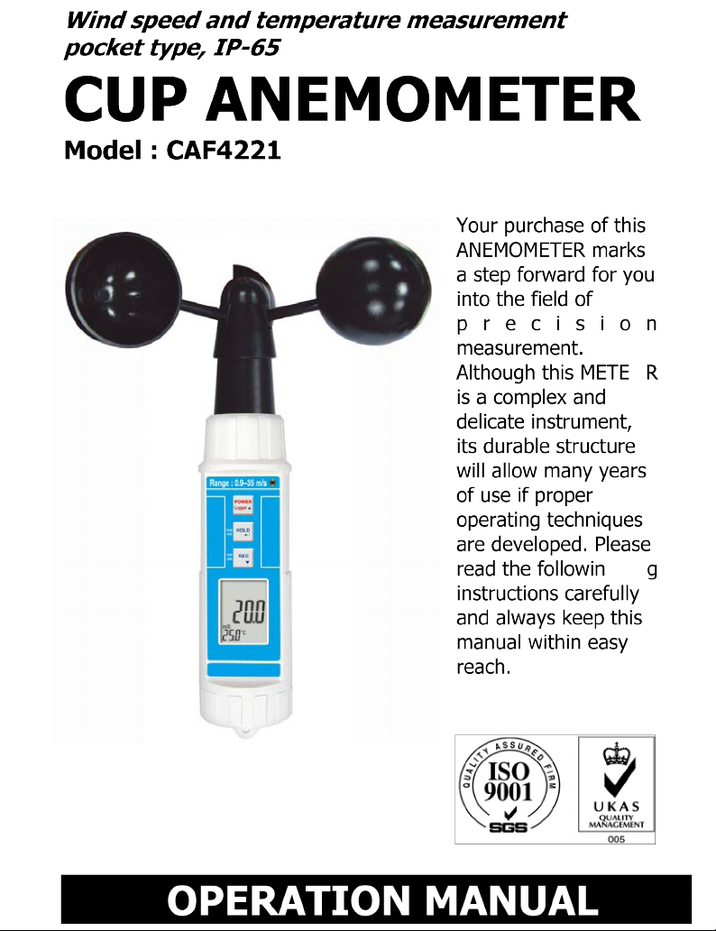
1. FEATURES
* Cup vane anemometer, available for wind speed
measurement, high reliability.
* Measurement range : 0.9 to 35.0 m/s
* Wind speed unit : m/s, km/h, ft/min, knot, mile/h.
* , temperature measurement.℃℉
* LCD display, IP 65 water resistance.
* Microprocessor circuit ensures high accuracy and
provides special functions and features.
* Records Maximum and Minimum readings with recall.
* Data hold and 100 point data logger with recall.
* Auto power off saves battery life.
* Operates from DC 1.5V ( UM4/AAA ) x 4 PCs batteries.
* Low-friction ball vane wheels is accurate in both high
and low velocities.
* Durable, long-lasting components, enclosed in strong,
compact ABS-plastic housing.
2. SPECIFICATIONS
2-1 General Specifications
Display LCD size : 1.1" x 0.8" (28 mm x 19 mm).
Wind speed m/S (meters per second)
Unit Km/h ( kilometers per hour )
Knot ( nautical miles per hour )
ft/min ( feet per minute )
mile/h ( miles per hour )
Temp. unit , ℃℉
Circuit Custom one-chip of microprocessor LSI
circuit.
1
Page 4
Temp. Sensor Thermister
Data Logger Max. can save 100 point data with recall.
Manual, push the data logger button
once will save data one time.
Sensor Cup van probe with low friction ball
Structure bearing design.
Data Hold Freeze the display reading.
Memory Recall Maximum & Minimum value.
Sampling Time Approx. 1 second.
Power off Auto shut off saves battery life or
manual off by push button.
Operating 32 to 122 F 0 to 50 .℃
Temp. and Less than 80% R.H.
Humidity
Power Supply DC 1.5 V battery ( UM4/AAA ) x 4 PCs,
Power Current Approx. DC 6.8 mA
Weight 181 g/ 0.4 LB.
Dimension
Main instrument :
@ Battery is included.
190 x 40 x 32 mm (7.5" x 1.6" x 1.3")
Cup vane ( 3 cups with arm ) :
135 mm dia.
Accessories Instruction manual......................1 PC
Included Carrying case............................. 1 PC
2-2 Electrical Specifications (23± 5 )℃
a. Wind speed
Measurement Range Resolution Accuracy
m/S 0.9 - 35.0 m/S 0.1 m/S ± ( 2%+0.2 m/S)
Km/h 2.5 - 126.0 Km/h 0.1 Km/h ± ( 2%+0.8 Km/h)
Knot 1.4 - 68.0 Knots 0.1 Knots ± ( 2%+0.4 Knots)
Ft/min 144 - 6895 Ft/min 1 Ft/min ± ( 2%+40 Ft/min)
Mile/h 1.6 - 78.2 Mile/h 0.1 Mile/h ± ( 2%+0.4 Mile/h)
@ reading
2
Page 5
b. Temperature
3-3 Hold ( Unit )Button
Measuring Range 0 to 50 /32 to 122 ℃℃℉ ℉
Resolution 0.1 /0. 1 ℃℉
Accuracy ± 0.8 /1.5 ℃℉
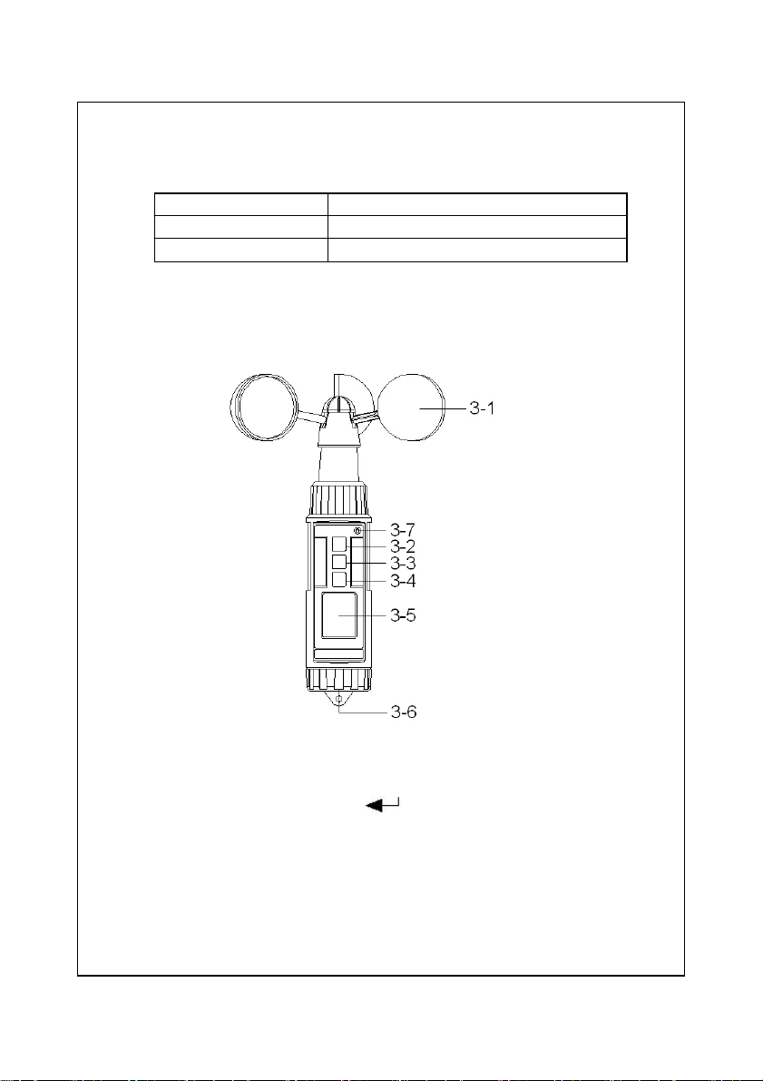
3. FRONT PANEL DESCRIPTION
Fig. 1
3-1 Cup Vane
3-2 Power ( Logger ) Button▲
3-4 REC ( ) Button, / Button▼℃℉
3-5 LCD Display
3-6 Battery Compartment/Cover
3-7 Temperature Sensor
3
Page 6
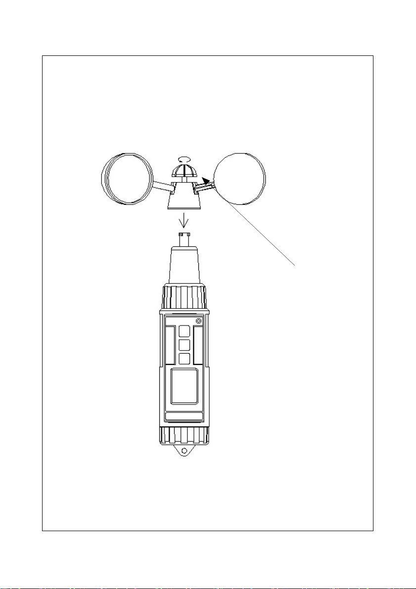
4. INSTALL THE VANE CUP
Rotate the top
screw in
counter
clockwise
direction until
the screw is
secured.
4
Page 7

5. MEASURING PROCEDURE
5-1 Wind speed and Temp. measurement
1)Turn on the meter by pressing the " Power Button "
( 3-2, Fig. 1 ) momentarily.
* Pressing the " Power Button " ( 3-2, Fig. 1 )
momentarily again will turn off the meter.
2)Uses the hand to hold the meter vertically. The " Cup
Vane " ( 3-1 ) will be rotated, shows the measured the
wind speed and temperature value on the " LCD
Display " ( 3-5, Fig. 1 ).
5-2 Wind speed unit change
1)Meter defaults unit value is " m/s ".
Meter unit value can be changed to " m/s, km/h,
knot, ft/min, mile/h "
2)The method to change the unit :
Press the '" Unit Button " ( 3-3, Fig. 1 ) continuously
( > 2 seconds ), the unit will change from m/s,
km/h, knot, ft/min, mile/h " in sequence. Until
reach the desired unit, release the finger from the
" Unit Button " ( 3-3, Fig. 1 ), new unit will saving
into the memory circuit no matter the meter is turned off.
* When the display shows " HOLD " ( refer 5-3 )
or " REC " ( refer 5-4 ), it can not change the unit.
5-3 Temp. unit ( , ) change℃℉
Press the '" / Button " ( 3-4, Fig. 1 ) continuously℃℉
( > 2 seconds ), the Temp. unit will change from
to ( or to ) ℃℉ ℉℃
5
Page 8

5-4 Data Hold
* During the measurement, press the " Hold Button "
( 3-3, Fig. 1 ) momentarily to hold the measured
value. The LCD will show a " HOLD " symbol.
* Press the" Hold Button " once again to release the
data hold function.
5-5 Data Record ( Max., Min. reading )
1)The data record function records the maximum and
minimum readings. Press the " REC Button " ( 3-4, Fig.
1 ) momentarily to start the Data Record function,
shows " REC " on the display.
2)With the " REC " symbol on the display.
a) Press the " REC Button " ( 3-4, Fig. 1 ) momentarily,
the " REC MAX " symbol along with the maximum
value will appear on the display.
b)Press the " REC Button " ( 3-4, Fig. 1 ) momentarily
again, the " REC MIN " symbol along with the
minimum value will appear on the display.
* When display shows " REC MAX " or " REC MIN ",
press the " Hold Button " ( 3-3, Fig. 1 )
momentarily will delete the max. ( min. ) value,
the display will show the " REC. " only and
execute the memory function continuously.
c) To exit the memory record function, press the
" REC " button for 2 seconds at least. The display will
revert to the current reading, not show " REC "
6
Page 9

6. DATA LOGGER
The meter can save max. 100 point data into the
the memory circuit
6-1 Save data
1)Turn on the meter.
2)Press the " REC Button " ( 3-4, Fig. 1 ) momentarily,
shows " REC " on the display.
3)Press the " Logger Button " ( 3-2, Fig. 1 ) momentarily
will save one measuring value to memory, display will
show :
Example :
28
a. The memory position that
72 save the recent data.
b. The memory left space no.
c. a + b = 100
For example : 28 + 72 = 100
4)To exit the memory data logger ( record ) function,
press the " REC " button for 2 seconds at least. The
display will revert to the current reading, not show
" REC "
7
Page 10

6-2 Call data
*
1)Turn on the meter.
Press the " Hold Button " ( 3-3, Fig. 1 ) momentarily,
LCD shows " HOLD ".
Following, press the " REC Button " ( 3-4, Fig. 1 )
momentarily, display shows :
Example :
28
The total data point that
ttL are saved into the memory.
2)Uses " Button " ( 3-2, Fig. 1 ) or " Button " ▲▼
( 3-4, Fig. 1 ) to call the data that already saved into
the memory.
Note :
During call the data, the unit display will be flashed.
Example :
1.5
m/s " m/s " unit flashing
25.1 ℃
* Press " Hold Button " ( 3-3. Fig. 1 ) will exit the
data call function.
8
Page 11

6-3 Delete data ( Empty the memory )
4)Press " Button " ( 3-3. Fig. 1 ) momentarily, the
1)Turn off the meter first.
2)Press the " REC Button " ( 3-4, Fig. 1 ) continuously and
not release, at the same time press the " Power
Button " ( 3-2, Fig. 1 ) momentarily, the display will
show following screen, then release both fingers from
the buttons.
n
CLr
3)Press " Button " momentarily, display shows :▼
y
CLr
display shows :
nuLL
CLr
Now all the saved data is deleted, memory will empty.
9
Page 12

7. BATTERY REPLACEMENT
* Replace the batteries when the left corner of the LCD
displays the low battery icon " ", using 4 fresh
1.5 V ( UM4, AAA ) batteries.
* T
o change the batteries, open ( rotate clockwise direction )
the " Battery Cover " ( 3-6, Fig. 1 ).
* Make sure the " Battery cover " (3-6, Fig 1) is secured
after changing the batteries.
10
0309-CAF4221
 Loading...