

Page 1
1
GB
CABLE FREETM WEATHER
STATION
MODEL: WMR968
USER’S MANUAL
SECTION 1 INTRODUCTION
Congratulations on your purchasing the WMR968 Cable Free
TM
Weather Station. An all-purpose easy-to-use system, the WMR968
lets you monitor the following weather elements:
- Air temperature
- Relative humidity
- Barometric pressure
- Wind speed and direction
- Rainfall
The WMR968 is also equipped with:
- Calendar clock with daily alarm
- Weather forecast within 32 to 48 km (20- to 30-mile) radius
- Weather alarms
- Memory for maximum and minimum readings
- Simple, touch-screen operation
- RS232 PC connection jack
-
backlight
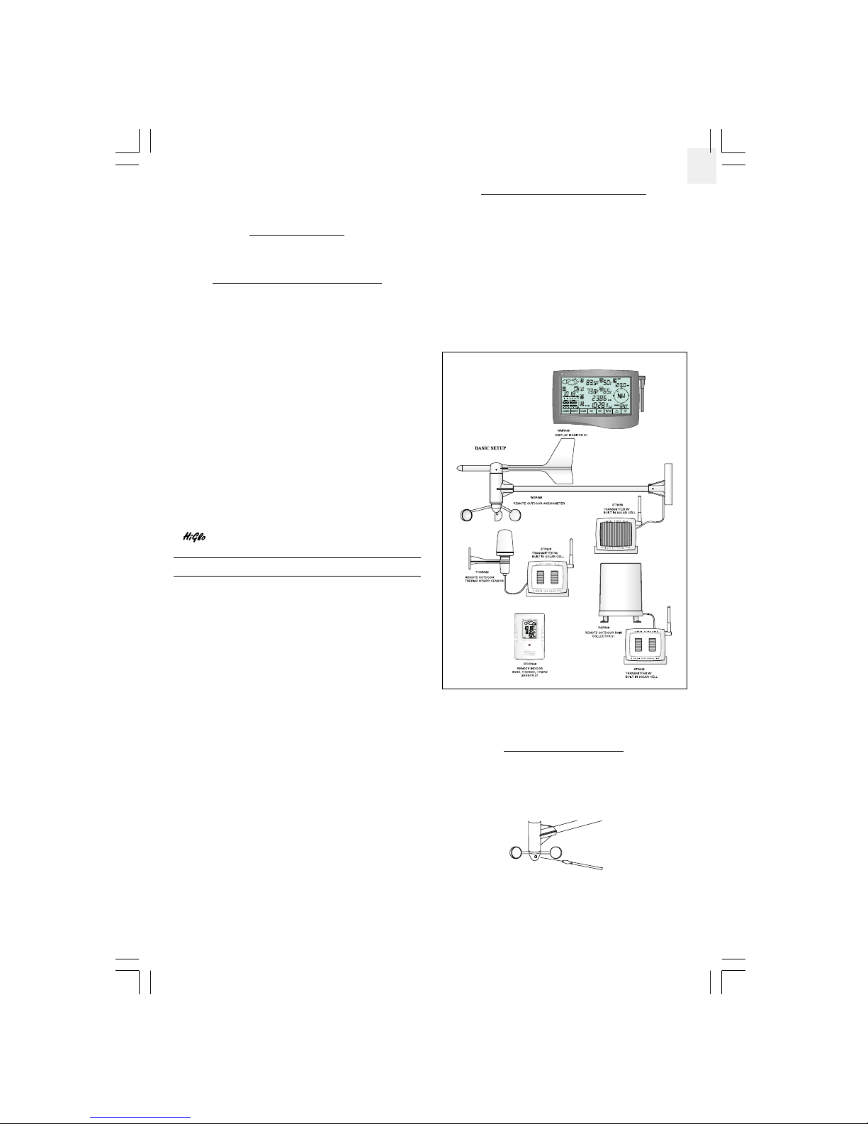
STANDARD PACKAGE
The original WMR968 comes complete with the following:
- Main unit (WMR968)
- Anemometer (WGR968)
- Thermo-hygrometer (THGR968)
- Rain gauge (RGR968)
- Baro-thermo-hygrometer (BTHR968)
- 12V AC adapter
The thermo-hygrometer and rain gauge are powered by solar
transmitters STR928 while the anemometer is powered by solar
transmitter STR938.
The WMR968 can support up to seven different remote instruments.
You can also connect up to three optional thermo or thermo-hygro
sensors to the system.
Optional items include:
- Thermo-hygro sensor (THGR238)
- Thermo sensor (THR238)
Contact an authorized dealer for optional items.
SECTION 2 INSTALLATION
The WMR968 operates at 433MHz. No wire installation is required
among units.
The WMR968 has an effective range of 109 yards in an open area.
Position the units within the range and be sure the transmission
path is clear of interference and obstacles.
Note:The anemometer, thermo-hygrometer and rain gauge should
be installed outdoors and in locations that best measure the weather
elements the instruments are designed for. As for the baro-thermohygrometer, it must be installed indoors. If you have any optional
thermo or thermo-hygro sensors, they can be installed outdoors or
indoors.
THE ANEMOMETER
The anemometer measures wind speed and direction.
To install it,
1. Place the wind cup over the thinnest shaft on the anemometer’s
T-bar.
2. Tighten the screw on the base of the wind cup.
928N-USE.p65 08/10/2001, 12:20 PM1
Page 2
2
GB
3. Align the red markings on the wind vane’s shaft.
4. With the aid of a compass, face the red marking south before
mounting the anemometer.
5. Mount the anemometer and its solar transmitter safely in place.
The wind speed and direction window on the main unit should read
180° if the main unit is installed.
THE THERMO-HYGROMETER
The thermo-hygrometer measures outdoor temperature and
humidity.
To install it:
Mount the thermo-hygrometer and its solar transmitter safely in
place.
THE RAIN GAUGE
The rain gauge measures the total amount and rate of rainfall.
To install it:
1. Open the cover of the rain collector.
2. Remove the fiber tape from around the bucket assemblies.
3. Mount the rain gauge and its solar transmitter safely in place.
4. Put drops of water on the cross at the base on the rain collector
to check the leveling.
5. Use metal ring to adjust the leveling of the rain collector if
necessary.
6. Close the cover of the rain collector.
THE SOLAR TRANSMITTERS
The solar transmitters make use of solar energy to power the
instruments they are connected to.
Note: It is recommended to insert two UM3 or “AA”-sized super
lithium batteries for weather condition under 0 °C (32 °F).
For the solar transmitters to function properly, make sure the solar
receptors on the transmitters are exposed to sunlight and the
connectors of the connection cable are securely plugged in.
THE BARO-THERMO-HYGROMETER
The baro-thermo-hygrometer measures the atmospheric pressure,
temperature and humidity.
The sensor uses four UM4 or “AAA”-sized batteries.
To install it,
1. Insert alkaline batteries accordingly.
2. Mount the unit where you want to monitor the readings. Or you
can make use of its table stand to place it on a flat surface.
Water stay at
position 1 - 4
means the gauge
is not leveled
METAL RING
928N-USE.p65 08/10/2001, 12:20 PM2
Page 3
3
GB
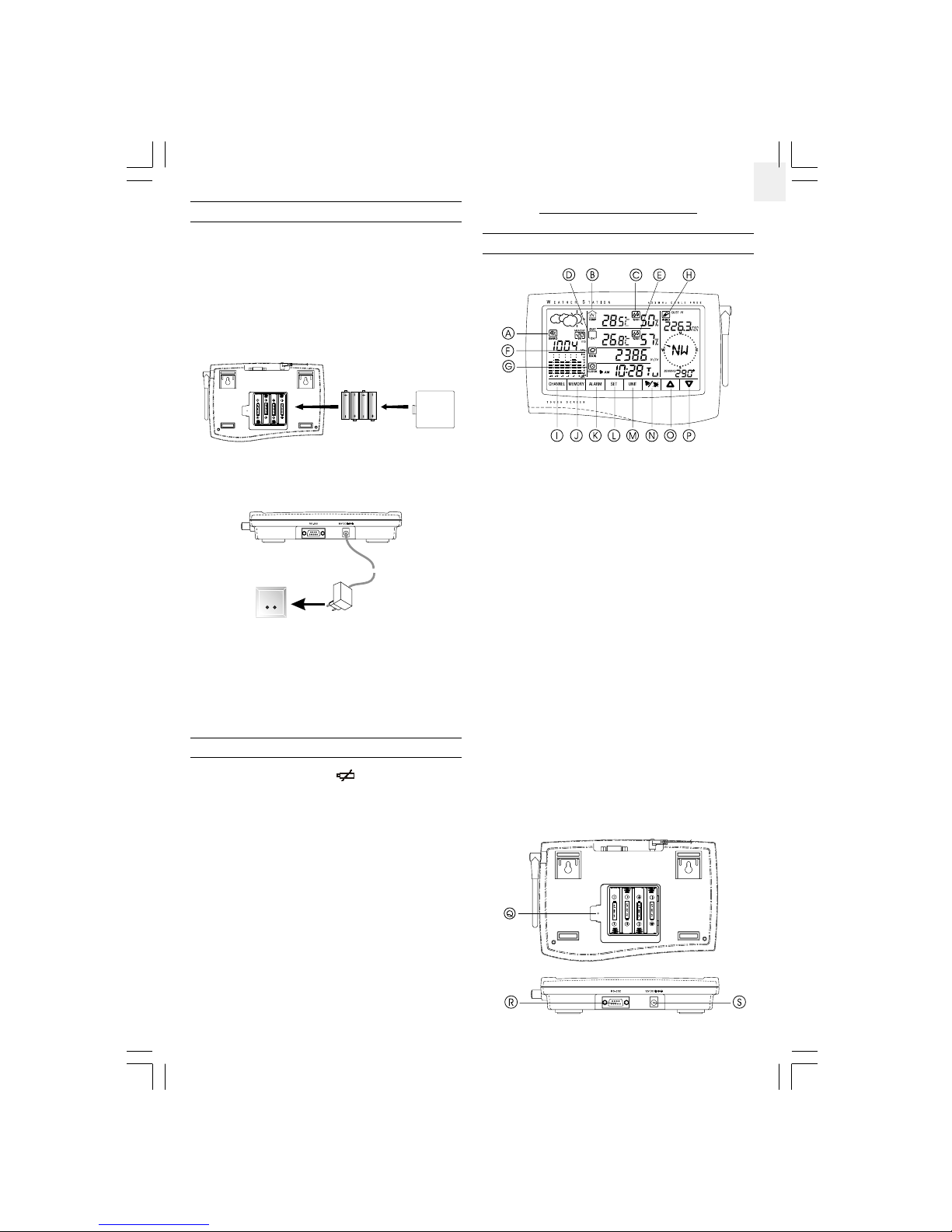
THE MAIN UNIT
The main unit gives you all the readings and controls. It should be
placed indoors.
The main unit is powered up by the 12V AC adapter.
To install it,
1. Position the main unit and other units within effective range
(109 yards).
2. Insert four UM3 or “AA”-sized alkaline batteries for backup
purpose.
3. Mount the main unit safely in place. Or use its table stand to
place it on a flat surface.
4. Connect the AC power adapter to the main unit and a wall socket.
5. Press the [RESET] button on the main unit to initiate operation.
The main unit will start searching for signals for about four minutes.
Upon successful reception, the readings will be displayed. The
main unit will update the readings at regular intervals.
Note: That if the main unit is operating solely on battery power, the
EL backlight and RS232 connection will be disabled.
LOW-BATTERY WARNING
There are low-battery indicators [
] for the main unit, rain
gauge, baro-thermo-hygrometer, thermo-hygrometer and optional
remote thermo and thermo-hygro sensors. Replace the batteries
when the respective indicators light up.
Note: The readings collected from the thermo-hygrometer and any
optional remote thermo and thermo-hygro sensors share the same
display window. The “OUT” and remote channel will share the same
low-battery indicator. When the battery level of the thermohygrometer is low, the low-battery indicator will turn on. If it is one
of the optional remote sensors, the low-battery indicator will
blink. To locate the channel in question, press the window to scan
through all available devices. The low-battery indicator will stop
blinking if the battery level is low for that one.
SECTION 3 OPERATION
THE MAIN UNIT
A. WEATHER FORECAST AND BAROMETRIC READING
WINDOW
B. INDOOR TEMPERATURE WINDOW
C. INDOOR HUMIDITY WINDOW
D. OUTDOOR/CHANNEL TEMPERATURE WINDOW
E. OUTDOOR/CHANNEL HUMIDITY WINDOW
F. RAINFALL WINDOW
G. CALENDAR CLOCK AND DAILY ALARM WINDOW
H. WIND SPEED AND DIRECTION WINDOW
I. CHANNEL BUTTON
J. MEMORY BUTTON
K. ALARM BUTTON
L. SET BUTTON
M. UNIT BUTTON
N. ALARM ON/OFF BUTTON
O. [U ] BUTTON
P. [V] BUTTON
Q. [ RESET] BUTTON
R. RS232 SERIAL PORT
S. DC 12V JACK
928N-USE.p65 08/10/2001, 12:20 PM3
Page 4

4
GB
BACKLIGHT
The main unit, when connected to the AC power, is equipped with
an automatic backlight. Every time you press a window on the main
unit, the
backlight will come on for a few seconds. This
function will be disabled for sole battery operation. The
backlight will also come on for a few seconds when the alarm is
triggered.
CALENDAR CLOCK
To set the calendar clock,
1. Press the calendar clock and alarm window.
2. Press and hold [V] to disable the radio reception function.
3. Press and hold [SET] till the digit flash.
4. Use [U] and [V] to change to the desired setting.
5. Press [SET] for the next item setting.
6. Repeat from Step 4 to finish all the settings for:
- Clock display formats (12hr or 24hr)
- Display language of the day-of-the-week
- Clock
- Calendar display formats (Month-Day, Day-Month)
- Calendar
For the display language, you can choose:
- English (E)
- German (D)
- French (F)
- Italian (I)
- Spanish (S)
7. Press [SET] to confirm.
The calendar clock and alarm window has three displays: clock
with seconds, clock with day-of-the-week and calendar. To change
from one display to another, press the window once.
The calendar clock also supports the following time zones:
- Pacific time (P)
- Mountain time (M)
- Central time (C)
- Eastern time (E)
To select a time zone,
1. Press and hold the calendar clock and alarm window.
2. Press [U] and [V] to change.
3. Press the window again to confirm.
THE DAILY ALARM
To set the daily alarm,
1. Press the calendar clock and alarm window.
2. Press [ALARM] and the indicator will be display to indicate
you are in the alarm mode.
3. Press and hold [SET] till the hour digit flash.
4. Use [U] and [V] to change to the desired setting.
5. Press [SET] for minutes setting.
6. Use [U] and V] to change to the desired setting.
7. Press [SET] to confirm.
Note: the window will show “
” if no alarm is armed.
Once set, the alarm clock will be activated automatically and the
alarm indicator
will light up. When an alarm goes off, press any
button to stop it. The alarm is still active and will go off again the
next day.
To deactivate the function,
1. Press the calendar clock and alarm window.
2. Press [ALARM ON/OFF]. The alarm indicator
will disappear.
WEATHER FORECAST
The weather forecast is displayed in the weather forecast and
barometric reading window.
There are four readings for the forecast: sunny, slightly cloudy,
cloudy and rainy.
INDOOR BAROMETRIC READING
The atmospheric pressure reading is displayed in the weather
forecast and barometric reading window.
The pressure reading can be displayed in mb (millibars), hPa
(Hecto-Pascal), inHg (inch mercury) or mmHg (millimeter mercury).
To select the display unit,
1. Press the weather forecast and barometric reading window.
2. Press [UNIT] repeatedly for the desired setting.
The pressure history for the past 24 hours is displayed in a six-
column bar chart.
To display the pressure reading for a particular hour within the
past 24 hours,
1. Press the weather forecast and barometric reading window.
2. Press [U] and [V] for the desired hour.
To set the sea-level pressure,
1. Press the weather forecast and barometric reading window
repeatedly till the “sea-level” icon is displayed.
2. Press [U] and [V] for the current (0 Hr) pressure.
3. Press and hold [SET].
4. Press [U] and [V] to change to the desired setting.
5. Press [SET] to confirm.
INDOOR AND DEW POINT TEMPERATURES
The current indoor and dew point temperatures, taken by the indoor
baro-thermo-hygrometer, are displayed on the indoor temperature
window. They can be displayed in degree Centigrade (ºC) or
Fahrenheit (ºF).
Forecast
Sunny Slightly Cloudy Cloudy Rainy
Indicator
displays on
the unit
928N-USE.p65 08/10/2001, 12:20 PM4
Page 5

5
GB
To select the display unit,
1. Press the indoor temperature window.
2. Press [UNIT] repeatedly for the desired setting. The selected unit
will apply to all temperature displays in this window.
Note: The unit of all temperature related display will be changed
simultaneously.
To display the dew point temperature, press the indoor temperature
window until the “DEW” indicator is displayed.
To display maximum, minimum temperatures,
1. Press the indoor temperature window or repeately until "DEW"
icon appear.
2. Press [MEMORY] repeatedly for the desired record. The time and
date of the record will also be displayed alternatively with
“STAMP” icon in the clock window.
The display will automatically return to the current temperature or
dew temperature whatever is displayed before if the unit is left
untouched for about one minute.
To clear the memory,
1. Press the indoor temperature window or repeately until "DEW"
icon appear.
2. Press and hold [MEMORY] till the key tone is heard.
3. Press [MEMORY] to check the memory is clear.
INDOOR HUMIDITY
The current indoor relative humidity, taken by the indoor barothermo-hygrometer, is displayed on the indoor hygrometer window.
To display the maximum, minimum and current humidity,
1. Press the indoor humidity window.
2. Press [MEMORY] repeatedly for the desired record. The time and
date of the record will also be displayed alternatively with
“STAMP” icon in the clock window.
To clear the memory,
1. Press the indoor humidity window.
2. Press and hold [MEMORY] till the key tone is heard.
3. Press [MEMORY] to check the memory is clear.
OUTDOOR AND CHANNEL TEMPERATURES
The temperature readings taken by the outdoor thermo-hygrometer
and separate thermo or thermo-hygro sensors are displayed on the
outdoor and channel temperature window.
As this window can display up to four different sets of data, specify
the instrument or channel you want to read.
To do so,
1. Press the outdoor/channel temperature window.
2. Press [CHANNEL] to go from the outdoor reading taken by the
outdoor thermo-hygrometer to those taken by individual sensors
(Channel 1, 2 or 3).
The outdoor thermo-hygrometer is also capable of detecting the
dew point temperature as well as the wind chill reading. To display
such information, press the window repeatedly.
The temperatures can be displayed in degree Centigrade (°C) or
Fahrenheit (°F).
To select the display unit,
1. Press the outdoor/channel temperature window.
2. Press [UNIT] repeatedly for the desired setting. The selected unit
will apply to all temperature displays in this window.
Note: The unit of all temperature related display will be changed
simultaneously.
To display the maximum, minimum temperatures,
1. Press the outdoor/channel temperature window or repeately until
"DEW" icon appear.
2. Press [CHANNEL] for the outdoor thermo-hygrometer or the
desired channel.
3. Press [MEMORY] repeatedly for the desired record. The time and
date of the record will also be displayed alternatively with
“STAMP” icon in the clock window.
To display the dew point temperature for a channel, press the
window again when the channel temperature is located.
To clear the memory,
1. Press the outdoor/channel temperature window or repeately until
"DEW" icon appear.
2. Press [CHANNEL] for the outdoor thermo-hygrometer or the
desired channel.
3. Press and hold [MEMORY] till the key tone is heard.
4. Press [MEMORY] to check the memory is clear.
OUTDOOR AND CHANNEL HUMIDITY
The relative humidity readings taken by the outdoor thermohygrometer and separate thermo-hygro sensors are displayed on
the outdoor/channel humidity window.
As this window can display up to four different sets of data, specify
the instrument or channel you want to read.
To do so,
1. Press the outdoor/channel humidity window.
2. Press [CHANNEL] to go from the outdoor reading taken by the
thermo-hygrometer to those taken by individual sensors
(Channel 1, 2 or 3).
To display the maximum, minimum and current humidity,
1. Press the outdoor/channel humidity window.
2. Press [CHANNEL] for the outdoor thermo-hygrometer or the
desired channel.
3. Press [MEMORY] repeatedly for the desired record. The time and
date of the record will also be displayed alternatively with
“STAMP” icon in the clock window.
To clear the memory,
1. Press the outdoor/channel humidity window.
2. Press [CHANNEL] for the outdoor thermo-hygrometer or the
desired channel.
3. Press and hold [MEMORY] till the key tone is heard.
4. Press [MEMORY] to check the memory is clear.
928N-USE.p65 08/10/2001, 12:20 PM5
Page 6

6
GB
To clear the record,
1. Press the wind speed and direction window.
2. Press and hold [MEMORY].
As for the wind direction, it is displayed in a digital compass with
bearing readouts.
WEATHER ALARMS
Weather alarms are used to alert you to certain weather conditions.
Once activated, the alarm will go off when a certain set criterion is
met.
You can set alarms for:
· Indoor, outdoor and channel high temperatures
· Indoor, outdoor and channel low temperatures
· Indoor, outdoor and channel dew point approaching
· Indoor, outdoor and channel high humidity
· Indoor, outdoor and channel low humidity
· High rainfall rate
· Pressure drop
· High gust wind
· Low wind chill
To set a weather alarm,
1. Press the window containing the weather element you want to
set.
2. Press [ALARM]. The current alarm setting will be displayed.
3. Press and hold [SET].
4. Press [U] and [V] for the desired setting.
5. Press [SET].
For temperatures and humidity, the high and low alarms can be set
in sequence. After entering the value for one alarm, you will be
prompted to enter the value for the other.
A weather alarm is activated once set. When the set criteria is met,
an alarm will go off and the current reading will flash together with
the corresponding indicator.
If that happens in the outdoor/channel temperature or humidity
window, the “OUT” indicator will flash to show that the criteria set
for the outdoor thermo-hygrometer has been met. If it is one of the
separate sensors, the [CHANNEL] indicator will flash. Press the
window repeatedly to locate the channel in question.
When a weather alarm goes off, press any button to stop the alarm.
The alarm is still active until you deactivate the function or the
criteria is no longer met.
To do so,
1. Press the window containing the weather element you want to
set.
2. Press [ALARM].
3. Press [ALARM ON/OFF] to deactivate the function.
To turn on the function again, simply follow the same procedure
and press [ALARM ON/OFF].
AUTO SCANNING FUNCTION
The auto scanning function is avalibable for the outdoor/channel
window for both the temperature and humidity.
To use it,
1. Press the outdoor/channel temperature or humidity window.
2. Press and hold [U] . The main unit will start scanning from the
active temperature and humidity display. Each channel will be
displayed for about 4 seconds.
To exit the auto scanning routine, press any window or control
button.
RAINFALL
The rate of rainfall can be displayed in mm/hr or in/hr.
To select the display unit,
1. Press the rainfall window.
2. Press [UNIT] for the desired setting.
To display the yesterday’s rainfall and the total rainfall from the
last cleared date,
1. Press the rainfall window.
2. Press [MEMORY] for the desired record. Yesterday rainfall will
be displayed with “YESTERDAY” shown in the rainfall window.
Total rainfall will be displayed with "TOTAL" shown in the
rainfall window. The time and date of the record will be displayed
alternatively with “SINCE” icon in the clock window for total
rainfall.
Note: Yesterday’s rainfall record will be updated when the real time
clock runs from 11:59:59 pm to 12:00:00 am. And it is counted for
12:00:00 am of one day to 12:00:00 am on the next day.
If the rain sensor detects no rainfall for about two consecutive
hours, the current rate of rainfall will be displayed as zero.
To clear the total rainfall,
1. Press the rainfall window.
2. Press and hold [MEMORY] till the key tone is heard.
The yesterday’s rainfall record will not be affected when you clear
the total rainfall.
WIND SPEED AND DIRECTION
The current wind speed and direction are displayed in the wind
speed and direction window.
To display the average wind speed, press the window till the
“AVERAGE” icon is displayed.
The wind speed can be displayed in m/s, kph, mph or knots.
To select the display unit,
1. Press the wind speed and direction window.
2. Press [UNIT] for the desired setting.
To display the maximum speed and direction for gust wind in
record,
1. Press the wind speed and direction window.
2. Press [MEMORY]. The time and date of the record will also be
displayed aternatively with “STAMP” icon in the clock window.
928N-USE.p65 08/10/2001, 12:20 PM6
Page 7

7
GB
DISCONNECTED SIGNALS
If without obvious reason the display for the main unit goes blank
or “
” are displayed, press and hold [CHANNEL] to enforce an
immediate search.
If that fails, check:
- All weather instruments are still in place.
- The batteries of the main unit and individual weather instruments
are still good. Replace them if necessary. Press and hold
[CHANNEL] to enforce an immediate search afterwards.
- The transmission is within range and path is cleared of obstacles
and interference. Shorten the distance if necessary.
Then press and hold [CHANNEL] again. The main unit will start
searching for all previously locked weather instruments.
If you want to add an new sensor, press the reset button on the new
sensor and then press channel to enforce the main unit to search.
Note: 1. Do not reset the sensors after the main unit has locked
those sensors, otherwise the main unit will no longer
receive the signal from those sensors.
2. If you have disconnected signals, you cannot clear the
memory.
THE RESET BUTTON
This button is only used when the system is operating in an
unfavorable way or malfunctioning. Use a blunt stylus to hold
down the button. The main unit will return to all default settings
and start searching for signals again.
Before resetting the main unit, you should do the same for all
weather instruments to ensure correct transmission and reception
of signals. Then press reset on the main unit.
MAINTENANCE
When handled properly, this unit is engineered to give you years
of satisfactory service. Here are a few product care instructions:
1. Do not immerse the unit in water. If the unit comes in contact
with water, dry it immediately with a soft lint-free cloth.
2. Do not clean the unit with abrasive or corrosive materials.
Abrasive cleaning agents may scratch the plastic parts and
corrode the electronic circuit.
3. Do not subject the unit to excessive: force, shock, dust,
temperature, or humidity. Such treatment may result in
malfunction, a shorter electronic life span, damaged batteries, or
distorted parts.
4. Do not tamper with the unit’s internal components. Doing so
will terminate the unit’s warranty and may cause damage. The
unit contains no user-serviceable parts.
5. Only use new batteries as specified in this instruction manual.
Do not mix new and old batteries as the old batteries may leak.
6. Read this instruction manual thoroughly before operating the unit.
SPECIFICATIONS
Temperature
Proposed Operating Range : Indoor ..... -5°C to 50°C
( 23°F to 122°F )
: Outoor ..... -20°C to 60°C
( -4°F to 140°F )
Resolution : 0.1°C (0.2°F)
(indoor and outdoor)
Relative Humidity
Measuring Range : 2 to 98% RH
(indoor and outdoor)
Resolution : 1% RH
(indoor and outdoor)
Dew Point Temperature
Measuring Range : Indoor ..... 0°C to 49°C
( 32°F to 120.2°F )
: Outoor ..... -10°C to 60°C
( 14°F to 140°F )
Resolution : 1°C (2°F)
(indoor and outdoor)
Barometric Pressure / Trend
Measuring Range : 795 to 1050 mb
(23.48 to 31.01 inHg)
Resolution : 1 mb (0.03 inHg)
Wind Speed
Measuring Range : 0 to 56 m/s (0 to 125.3 mph)
Resolution : 0.2 m/s (0.4 mph) (typical)
Wind Direction
Measuring Range : 0° to 359° (Degrees)
Digital Resolution : 1° (typical)
Graphical Resolution : 10°
Wind Chill Temperature
Measuring Range : -52°C to 60°C (-61.6°F to 140°F)
Resolution : 1°C (2°F)
Rainfall
Daily and Cumulative : 0 to 9999 mm (0 to 393.7 in)
Measuring Range
Rainfall Rate : 0 to 999 mm/hr (0 to 39.37 in/hr)
Measuring Range
Daily and Cumulative : 1 mm (0.04 inch)
Resolution
Rainfall Rate Resolution : 1mm/hr (0.04 m/h) typical
WMR968 :
Weight : 505 g
Dimension : 204 (L) x 139 (W) x 39 (H)
Power : 12V AC / DV adapter
Power backup : 4 x UM3 - “AA” size alkaline battery
WGR968 :
Weight : 430 g
Dimension : 295 (L) x 116.5 (W) x 550 (H)
Power : solar cell (STR918)
928N-USE.p65 08/10/2001, 12:20 PM7
Page 8

8
GB
THGR968 :
Weight : 111.5 g
Dimension : 113.5 (L) x 42.5 (W) x 107.5 (H)
Power : Main : solar cell (STR918)
RGR968 :
Weight : 276 g
Dimension : Ø 113.5 x 145 (H)
Power : Main : sole cell (STR918)
BTHR968 :
Weight : 78.4 g
Dimension : 180 (L) x 70 (W) x 19 (H)
Power : 4 x UM4 - “AAA” size alkaline battery
STR928 :
Weight : 266 g
Dimension : 115 (L) x 81 (W) x 138 (H)
Power back up : 2 x UM3- “AA” size alkaline battery
(recommend super lithium battery for
weather condition under 32°F)
STR938 :
Weight : 290 g
Dimension : 115 (L) x 81 (W) x 138 (H)
Power back up : 2 x UM3- “AA” size alkaline battery
(recommend super lithium battery for
weather condition under 32°F)
NOTE ON COMPLIANCE
Warning: Changes or modifications to this unit not expressly
approved by the party responsible for compliance could void the
user’s authority to operate the equipment.
FCC :
NOTE: This equipment has been tested and found to comply with
the limits for a Class B digital device, pursuant to Part 15 of the
FCC Rules. These limits are designed to provide reasonable
protection against harmful interference in a residential installation.
This equipment generates, uses and can radiate radio frequency
energy and, if not installed and used in accordance with the
instructions, may cause harmful interference to radio
communications.
However, there is no guarantee that interference will not occur in a
particular installation. If this equipment does cause harmful
interference to radio or television reception, which can be determined
by turning the equipment off and on, the user is encouraged to try
to correct the interference by one or more of the following measures:
Reorient or relocate the receiving antenna.
Increase the separation between the equipment and receiver.
Connect the equipment into an outlet on a circuit different from
that to which the receiver is needed.
Consult the dealer of an experienced radio/TV technician for
help.
R&TTE Compliance Note
This device complies with the essential requirements of Article 3
of the R&TTE 1999/5/EC Directive, if used for its intended use and
that the following standard(s) has been applied:
Electromagnetic compatibility (Article 3.1.b of the R&TTE Directive)
Applied standards ETS 300 683 : 1997
Efficient use of the radio frequency spectrum (Article 3.2 of the
R&TTE Directive)
Applied standards EN300 220 –1 : 1997
INTENDED USE OF THE DEVICE
CAUTION
— The content of this manual is subject to change without
further notice.
— Due to printing limitation, the displays shown in this
manual may differ from the actual display.
— The contents of this manual may not be reproduced
without the permission of the manufacturer.
928N-USE.p65 08/10/2001, 12:20 PM8
 Loading...